1
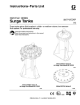
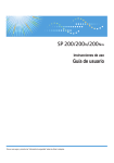
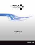
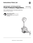
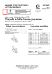
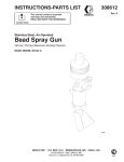
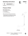
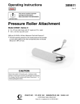
INSTRUCTIONS-PARTS LIST
307628
Rev. S
This manual contains important
warnings and information.
READ AND KEEP IT FOR REFERENCE.
First choice when
quality counts.t
INSTRUCTIONS
316 Series Stainless Steel, Closed Cavity
Low-Pressure Ball Valves
500 psi (35 bar, 3.5 MPa) Maximum Fluid Working Pressure
NOTE: npsm threaded ends meet SAE J516 fitting recommendations.
Refer to page 2 for Table of Contents.
Models
237528
through
237535
and
239079
8691A
Models
237541
238143
Model 237542
List of Models
Model 237536
Model 237537
Models 237538, 237539, and 237540
Model
237528
237529
237530
237531
237532
237533
237534
237535
237536
Series
C
C
C
C
C
C
C
C
C
237537
237538
237539
237540
237541
237542
C
C
C
C
C
C
238143
239079*
B
B
Thread
1/4 npt(m) x 1/4 npt(m)
1/4 npt(m) x 3/8 npsm(m)
3/8 npt(m) x 1/4 npt(m)
3/8 npt(m) x 3/8 npt(m)
3/8 npt(f) x 3/8 npt(f)
3/8 npsm(m) x 3/8 npt(m)
3/8 npt(f) x 3/8 npt(m)
3/8 npt(f) x 3/8 npsm(m)
3/8 O.D. tube end x 3/8
npsm(m)
3/8 tube fitting (both ends)
3/8 tube fitting x 3/8 npt(m)
3/8 tube fitting x 3/8 npsm(m)
1/2 tube fitting x 3/8 npsm(m)
1/2 tube fitting x 3/8 npsm(m)
3/8 O.D. tube end x
3/8 tube fitting
3/8 tube fitting x 3/8 npsm(m)
1/4 npt(f) x 1/4 npt(m)
*Special order.
GRACO INC.
P.O. BOX 1441
MINNEAPOLIS, MN
ECOPYRIGHT 1994, GRACO INC.
Graco Inc. is registered to I.S. EN ISO 9001
55440–1441
Table of Contents
List of Models . . . . . . . . . . . . . . . . . . . . . . . . . . . . . . . .
Warnings . . . . . . . . . . . . . . . . . . . . . . . . . . . . . . . . . . . . .
General Information . . . . . . . . . . . . . . . . . . . . . . . . . . .
Ball Valve Applications . . . . . . . . . . . . . . . . . . . . . . .
Tubing Selection . . . . . . . . . . . . . . . . . . . . . . . . . . . .
1
2
3
3
3
Installation . . . . . . . . . . . . . . . . . . . . . . . . . . . . . . . . . . .
Models 237537 through 237542
and 238143 Only . . . . . . . . . . . . . . . . . . . . . . . . . . .
All Other Models . . . . . . . . . . . . . . . . . . . . . . . . . . . .
Retightening a Tube Fitting . . . . . . . . . . . . . . . . . . .
Technical Data . . . . . . . . . . . . . . . . . . . . . . . . . . . . . . . .
Graco Standard Warranty . . . . . . . . . . . . . . . . . . . . . .
Graco Phone Number . . . . . . . . . . . . . . . . . . . . . . . . .
Warnings
Warning Symbol
Caution Symbol
WARNING
CAUTION
This symbol alerts you to the possibility of serious
injury or death if you do not follow the instructions.
This symbol alerts you to the possibility of damage to
or destruction of equipment if you do not follow the
instructions.
WARNING
EQUIPMENT MISUSE HAZARD
INSTRUCTIONS
Spray from the gun, hose leaks, or ruptured components can splash fluid in the eyes or on the skin
and cause serious injury.
To reduce the risk of splashing follow the pressure relief procedure for your equipment before
removing the valve.
Do not stop or deflect fluid leaks with your hand, body, glove, or rag.
Equipment misuse can cause the equipment to rupture, malfunction, or start unexpectedly and
result in serious injury.
D This equipment is for professional use only.
D Read all instruction manuals, warnings, tags, and labels before operating the equipment.
D Use the equipment only for its intended purpose. If you are uncertain about usage, call your
Graco distributor.
D Do not alter or modify this equipment. Use only genuine Graco parts and accessories.
D Check the equipment daily. Repair or replace worn or damaged parts immediately.
D Never exceed the recommended working pressure of the lowest rated system component. This
equipment has a maximum fluid working pressure of 35 bar, 3.5 MPa (500 psi).
D Use only fluids and solvents that are compatible with the equipment wetted parts. See the
Technical Data sections of all the equipment manuals. Read the fluid manufacturer’s warnings.
D Always wear protective eyewear, gloves, clothing, and respirator as recommended by the fluid
and solvent manufacturers.
D Comply with all applicable local, state and national fire, electrical and other safety regulations.
2
307628
3
4
4
4
4
6
6
General Information
Ball Valve Applications
Models 237528 through 237535 and 239079 have
both ends threaded for pipe connections.
Models 237538, 237539 and 237540 have a
compression nut on one end for connecting the valve
to tubing. The other end is threaded for pipe
connection.
Models 237541 and 238143 have a compression nut
on one end for connecting the valve to tubing. The
other end is threaded for pipe connection. These
valves also include a jam nut to use if mounting the
valve on a panel.
Model 237537 has compression nuts on both ends, for
connecting the valve to tubing.
Model 237536 has a 1 in. length of tubing on one end,
for connecting the valve to a compression fitting. The
other end is threaded for pipe connection.
Model 237542 has a 1 in. length of tubing on one end,
for connecting the valve to a compression fitting. The
other end has a compression nut for connecting the
valve to tubing.
Tubing Selection
Tubing material, hardness, surface finish, and wall
thickness must be considered to ensure the proper
installation and operation of the ball valves. These ball
valves are recommended for use with either carbon
steel or stainless steel tubing. The tubing outer surface
should be free of scratches and the tubing ends should
always be deburred to prevent leakage or damage to
the ferrules during installation.
Installation
NOTES:
D This procedure applies to ball valves that have
compression nuts or compression fittings.
D Letters in parentheses in the text refer to Figs. 1
and 2.
D The valves are shipped fully assembled, with the
compression nut finger tight.
CAUTION
Do not disassemble the valve before installing it on
the tubing as this may allow dirt to get in between the
ferrules, resulting in leakage.
When installing the valve near a bend in the tubing,
allow a sufficient straight length of tubing to ensure
that the tubing end will seat firmly on the shoulder in
the adapter or housing. See Fig. 1.
Model
238143
237537
237538
237539
237540
237541
237542
L1 =
L2 =
L1
15/16”
15/16”
15/16”
15/16”
1–3/16”
1–3/16”
15/16”
L2
3/4”
3/4”
3/4”
3/4”
31/32”
31/32”
3/4”
Recommended straight length of tubing required
Absolute minimum straight length of tubing
required
To ensure a leak–free installation, the tubing must be
softer than the ferrules in the ball valve fitting.
Therefore, the tubing must meet the following material
specifications:
L
Tubing Material Specifications
1. Carbon Steel Tubing: High quality soft annealed
seamless carbon steel hydraulic tubing ASTM
A–179 or equivalent; hardness of Rb 72 or less;
0.035 in. (20 ga) minimum recommended wall
thickness
A
B
02726
Fig. 1
2. Stainless Steel Tubing: Fully annealed (type 304,
316, etc.) seamless or welded and drawn stainless
steel hydraulic tubing ASTM A–269, ASTM A–213
or equivalent; hardness of Rb 80 or less; 0.035 in.
(20 ga) minimum recommended wall thickness.
307628
3
All Other Models
Installation
NOTE: This procedure applies only to models with
compression nuts or fittings.
1. Be sure the compression nut (A) is finger tight.
(Model 237537 has a compression nut on each
end.)
D
A
2. Insert the tubing into the compression nut (A) and
adapter (B).
On Model 237537 only, insert another length of
tubing into the second compression nut (D) and
housing (C). See Fig. 2.
B
C
Model 237537 shown
3. Be sure the tubing seats firmly on the shoulder.
Tighten the compression nut(s) until finger tight.
Fig. 2
Models 237536 through 237542 and
238143 Only
1. Be sure the compression nut (A) is finger tight.
2. Insert the 3/8 in. O.D. tube end of the valve into
the compression fitting. Make sure the tubing
seats firmly on the shoulder. Tighten the
compression nut finger tight.
3. While holding the adapter (B) with a wrench,
tighten the compression nut 1–1/4 turns with
another wrench.
4. Refer to the note at the end of All Other Models
on this page for additional tightening and
retightening information.
4. While holding the adapter (B) with a wrench,
tighten the compression nut (A) 1 turn with another
wrench.
On Model 237537 only, tighten the second
compression nut (D) the same amount, but hold
the housing (C) with a wrench while tightening.
NOTE: When installing the ball valves on tubing with a
hardness close to the maximum recommended, more
force is required to tighten the nut than the full 1 turn
specified above. Be sure that the nut is tightened
sufficiently.
Retightening a Tube Fitting
Tube fittings can be disconnected and retightened.
To retighten tube fittings, insert the tubing into the
adapter or housing until the ferrule seats on the
shoulder. Tighten the nut to finger tight. Then, using a
wrench, tighten the nut to its original position, plus 1
flat.
Technical Data
Category
Maximum fluid working pressure
Wetted parts
Canadian Registration Number (CRN):
Alberta – 0C4155.2
Ontario – 0C4874.5
4
307628
Data
35 bar, 3.5 MPa (500 psi)
316 Series Stainless Steel, PTFE r
Models: 237528, 237529, 237530, 237531, 237532, 237533,
237534, 237535, 237536, 237537, 237538, 237539, 237540,
237541, 237542, 237543, and 239079
Notes
307628
5
Graco Standard Warranty
Graco warrants all equipment referenced in this document which is manufactured by Graco and bearing its name to be free from
defects in material and workmanship on the date of sale by an authorized Graco distributor to the original purchaser for use. With the
exception of any special, extended, or limited warranty published by Graco, Graco will, for a period of twelve months from the date of
sale, repair or replace any part of the equipment determined by Graco to be defective. This warranty applies only when the equipment
is installed, operated and maintained in accordance with Graco’s written recommendations.
This warranty does not cover, and Graco shall not be liable for general wear and tear, or any malfunction, damage or wear caused by
faulty installation, misapplication, abrasion, corrosion, inadequate or improper maintenance, negligence, accident, tampering, or
substitution of non–Graco component parts. Nor shall Graco be liable for malfunction, damage or wear caused by the incompatibility
of Graco equipment with structures, accessories, equipment or materials not supplied by Graco, or the improper design, manufacture,
installation, operation or maintenance of structures, accessories, equipment or materials not supplied by Graco.
This warranty is conditioned upon the prepaid return of the equipment claimed to be defective to an authorized Graco distributor for
verification of the claimed defect. If the claimed defect is verified, Graco will repair or replace free of charge any defective parts. The
equipment will be returned to the original purchaser transportation prepaid. If inspection of the equipment does not disclose any defect
in material or workmanship, repairs will be made at a reasonable charge, which charges may include the costs of parts, labor, and
transportation.
THIS WARRANTY IS EXCLUSIVE, AND IS IN LIEU OF ANY OTHER WARRANTIES, EXPRESS OR IMPLIED, INCLUDING BUT
NOT LIMITED TO WARRANTY OF MERCHANTABILITY OR WARRANTY OF FITNESS FOR A PARTICULAR PURPOSE.
Graco’s sole obligation and buyer’s sole remedy for any breach of warranty shall be as set forth above. The buyer agrees that no other
remedy (including, but not limited to, incidental or consequential damages for lost profits, lost sales, injury to person or property, or any
other incidental or consequential loss) shall be available. Any action for breach of warranty must be brought within two (2) years of the
date of sale.
GRACO MAKES NO WARRANTY, AND DISCLAIMS ALL IMPLIED WARRANTIES OF MERCHANTABILITY AND FITNESS FOR
A PARTICULAR PURPOSE, IN CONNECTION WITH ACCESSORIES, EQUIPMENT, MATERIALS OR COMPONENTS SOLD
BUT NOT MANUFACTURED BY GRACO. These items sold, but not manufactured by Graco (such as electric motors, switches,
hose, etc.), are subject to the warranty, if any, of their manufacturer. Graco will provide purchaser with reasonable assistance in
making any claim for breach of these warranties.
In no event will Graco be liable for indirect, incidental, special or consequential damages resulting from Graco supplying equipment
hereunder, or the furnishing, performance, or use of any products or other goods sold hereto, whether due to a breach of contract,
breach of warranty, the negligence of Graco, or otherwise.
FOR GRACO CANADA CUSTOMERS
The parties acknowledge that they have required that the present document, as well as all documents, notices and legal proceedings
entered into, given or instituted pursuant hereto or relating directly or indirectly hereto, be drawn up in English. Les parties
reconnaissent avoir convenu que la rédaction du présente document sera en Anglais, ainsi que tous documents, avis et procédures
judiciaires exécutés, donnés ou intentés à la suite de ou en rapport, directement ou indirectement, avec les procedures concernées.
Graco Phone Numbers
TO PLACE AN ORDER, contact your Graco distributor, or call one of the following numbers
to identify the distributor closest to you:
1–800–367–4023 Toll Free
612–623–6921
612–378–3505 Fax
All information, illustrations and specifications in this document are based on the latest product information available at the time
of publication. The right is reserved to make changes at any time without notice.
Sales Offices: Minneapolis, Detroit
International Offices: Belgium, Korea, Hong Kong, Japan
GRACO INC.
P.O. BOX 1441 MINNEAPOLIS, MN 55440–1441
www.graco.com
6
307628
PRINTED IN U.S.A. 307628 January 1983, Revised April 2001