1
INSTRUCTIONS-PARTS LIST
307–730
This manual contains IMPORTANT
INSTRUCTIONS and WARNINGS.
READ AND RETAIN FOR REFERENCE.
1/4 Gallon Per Minute, 120 V AC, 60 Hz
PT2000
Rev G
Supersedes E
(and F, not published)
APPLICATION EQUIPMENT FROM GRACO
Pressure Roller System
250 psi (17.5 bar) MAXIMUM WORKING PRESSURE
Model 218–938, Series B
with 18 inch Extension and 1/2 and 3/4 inch nap Roller Covers
Model 223–660, Series A
Basic Pressure Roller, without hose, gun, extension or roller
U.S. Patent No. 4,722,230; 4,652,024
Foreign Patents Pending
CONTENTS
Terms . . . . . . . . . . . . . . . . . . . . . . . . . . . . 2
Warnings . . . . . . . . . . . . . . . . . . . . . . . . . 2
System Description . . . . . . . . . . . . . . . . 5
Setup . . . . . . . . . . . . . . . . . . . . . . . . . . . . 6
Startup . . . . . . . . . . . . . . . . . . . . . . . . . . . 7
Operation . . . . . . . . . . . . . . . . . . . . . . . . 7
Maintenance
Flushing . . . . . . . . . . . . . . . . . . . . . . . 8
Roller Cover . . . . . . . . . . . . . . . . . . . 9
Troubleshooting Chart . . . . . . . . . . . . 10
Repair
Roller Valve . . . . . . . . . . . . . . . . . . . 11
Fuse . . . . . . . . . . . . . . . . . . . . . . . . . 12
ON/OFF Switch . . . . . . . . . . . . . . . 12
Rectifier . . . . . . . . . . . . . . . . . . . . . . 12
Power Supply Cord . . . . . . . . . . . . 12
Pressure Switch . . . . . . . . . . . . . . . 13
Outlet Valve . . . . . . . . . . . . . . . . . . . 13
Inlet Valve . . . . . . . . . . . . . . . . . . . . 13
Diaphragm . . . . . . . . . . . . . . . . . . . . 14
Suction Tube . . . . . . . . . . . . . . . . . . 14
Priming Valve & Tube . . . . . . . . . . 14
Motor, Conn Rod, Bearing . . . . . . 15
Parts Drawing & Lists . . . . . . . . . . . . . 16
Accessories . . . . . . . . . . . . . . . . . . . . . 19
Technical Data . . . . . . . . . . . . . . . . . . . 20
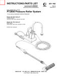
Model 218–938 shown
Always Professional Results
GRACO INC.
P.O. BOX 1441 MINNEAPOLIS, MN
COPYRIGHT 1985, GRACO INC.
55440–1441
CAUTION
To avoid premature wear of the pressure switch, never use more than 25 ft (7.6 m) of 1/4” ID outlet hose. When
longer outlet hose is needed, use 3/8” ID hose at a maximum of 100 ft (30 m) long. Never use 1/4” ID and 3/8” ID
hose together.
Do not use lacquer or lacquer thinner in the suction and outlet hoses supplied with this system. These fluids quickly
destroy the hose material. Use the optional chemical–resistant hoses.
See ACCESSORIES section of the manual for ordering optional hoses.
TERMS
Be sure you read and understand each of these terms before reading the rest of the manual.
CAUTION: Alerts user to avoid or correct conditions
which could damage or destroy the equipment.
WARNING: Alerts user to avoid or correct conditions
which could cause bodily injury.
NOTE: Gives additional explanation of a procedure or
helpful hints.
WARNING
Be sure all operators of this equipment read, understand,
and follow the warnings and instructions in this manual !
GENERAL SAFETY
EQUIPMENT MISUSE HAZARD
Use extreme care not to splash paint,
contaminated
flushing water, or solvent into your eyes. Wear protective
eyewear.
This system is designed to be used at 250 psi (17.5 bar)
MAXIMUM WORKING PRESSURE . Use only components or accessories which are designed for use with the
PT2000 System.
Be sure the area in which you are working is well ventilated, to avoid a buildup of harmful paint fumes.
To reduce the risk of electric shock, do not expose the
system to rain. Always store the system indoors. Do not
operate the pump with the base cover removed.
ELECTRICAL GROUNDING
Electrical grounding is essential to reduce the risk of an
electric shock or other serious bodily injury from static
sparking. Read and follow the grounding instructions on
page 6 of this manual.
EXTENSION MISUSE HAZARD
Do not attempt to modify the extension or roller frame, or
to use parts which are not designed for use with this system. Use the extension only with the roller frame provided
with this system.
Improper use of the extension, roller frame, hose or roller
valve can result in component rupture or explosion and
cause serious bodily injury.
307-730
Any misuse of this equipment, such as modifying parts,
using incompatible paint or solvent, or using worn or
damaged parts, can cause the equipment to rupture and
result in serious bodily injury, fire, explosion and property
damage.
Never alter or modify any part of this equipment; doing so
could cause it to overpressurize or malfunction.
Check all parts of the system regularly and repair or replace any worn or damaged parts immediately.
AVOID POWER LINES
Avoid contacting any power lines with the extension.
Contact with power lines could cause extremely serious
bodily injury, including burns or electrocution.
HAZARD OF USING FLUIDS CONTAINING
HALOGENATED HYDROCARBONS
Never use 1,1,1–trichloroethane, methylene chloride,
other halogenated hydrocarbon solvents or fluids containing such solvents in this equipment. Such use could
result in a serious chemical reaction, with the possibility
of explosion, which could cause death, serious bodily injury and/or substantial property damage.
Consult your material suppliers to ensure that the fluids
being used are compatible with aluminum and zinc parts.
AVERTISSEMENT
Assurez–vous que tous les utilisateurs de cet équipment lisent, comprennent et
observent les avertissements et les instructions de ce manuel!
SECURITE GENERAL
Faites extrêmement attention de ne pas éclabousser de
peinture, d’eau de rinçage sale ni de solvant dans les
yeux. Portez de lunettes de protection.
Assurez-vous que l’endroit où vous travaillez est bien
aéré afin d’éviter l’accumulation des vapeurs toxiques de
peinture.
Pour réduire le risque de décharge électrique, n’exposez
pas le système à la pluie. Rangez toujours le système à
l’intérieur.
MISE A LA TERRE
Il est essentiel d’effecteur la mise à la terre pour réduire
le risque de décharge électrique et de blessures
sérieuses résultant des étincelles d’électricité statique.
Lisez et observez les instuctions de mise à la terre, à la
page 6 de ce manuel.
DANGERS POUVANT RESULTER DU
MAUVAIS USAGE DE LA RALLONGE
N’essayez pas de modifier la rallonge ni la monture du
rouleau; n’essayez pas non plus d’utiliser de pièces qui
ne sont pas conçues pour aller avec ce système. N‘utilisez la rallonge qu’avec la monture de rouleau fournie
avec le système.
L’utilisation incorrecte de la rallonge, de la monture de
rouleau, du tuyau ou du robinet du rouleau peut entraîner
la rupture de pièces ou une explosion et causer des blessures sérieuses.
DANGERS POUVANT RESULTER DU
MAUVAIS USAGES DE L‘EQUIPMENT
Ce système est conçu pour être utilisé à une PRESSION
MAXIMUM DE FONCTIONNEMENT de 17.5 bars (250
psi). N’utilisez que des pièces ou accessoires qui sont
conçus pour être utilisés avec le système PT2000.
L’utilisation incorrecte de cet équipement, la modification
des pièces, l’utilisation de peinture ou de solvant incompatibles, l’utilisation de pièces usées ou abîmées peuvent entrainer la rupture de l’équipement et causer des
blessures graves, un incendie, une explosion et des
dégâts matériels.
Ne changez et ne modifiez jamais aucune pièce du
système et réparez ou remplacez les piéces usées ou
abîmées immédiatement.
Vérifiez régulièrement toutes les pièces du système et
réparez ou remplacez les pièces usées ou abîmées
immédiatement.
EVITEZ LES LIGNES ELECTRIQUES
Evitez tout contact avec les lignes électriques! Ceci pourrait causer des blessures très graves, y compris des
brûlures ou l’électrocution.
307-730
3
ADVERTENCIA
Asegurarse de que todos los operadores de este equipo lean, entiendan
y repeten las precauciones e instrucciones indicadas en este manual.
SEGURIDAD EN GENERAL
Tener extremo cuidado de no salpicarse los ojos con
pintura, agua de enjuague contaminada o solvente. Usar
gafas protectoras.
Asegurarse de que el lugar de trabajo tenga buena
ventilición, para evitar la acumulación de vapores de
pintura nocivos.
Para reducir el riesgo de sufrir un choque eléctrico, no
Siempre
dejar este sistema expuesto a la lluvia.
guardarlo bajo techo.
PUESTA A TIERRA
La puesta a tierra es esencial para reducir el riesgo de
sufrir un choque eléctrico u otras lesiones corporales
graves debido a chispas estáticas. Leer y seguir las
instrucciones dadas en la pàgina 6 de este manual.
PELIGRO POR MAL USO DEL EQUIPO
Este sistema está diseñado para una
PRESION DE
TRABAJO MAXIMA de 17.5 barías (250 lbs/pulg2). Usar
componentes o accesorios diseñados para usarse con
el sistema PT2000.
El uso indebido de este equipo, tal como modificación de
las piezas, uso de pintura o solvente incompatible, o de
piezas dañadas o desgastadas, podría causer la rotura
del equipo y terminar en graves lesiones personales,
incendio, explosión y daños a la propiedad.
Nunca alterar o modificar ninguna pieza del equipo;
el hacerlo podría causar sobrepresión o malfuncionamiento.
PELIGRO POR MAL USO
DE LA EXTENSION
Revisar con regularidad todas las piezas del sistema y
reparar o sustituir de inmediato las que estén dañadas o
desgastadas.
No intentar modificar las extensión o el portarradillo, o
usar piezas que no hayan sido diseñadas para usarse en
este sistema. Usar la extensión solamente con el
portarrodillo provisto con este sistema.
PROCURAR NO TOCAR
LOS CABLES ELECTRICOS
El uso indebido de la extensión, portarrodillo, manguera
o gatillo del rodillo podría romper o hacer explotar el
componente y causar graves lesiones corporales.
¡Procurar no tocar ningún cable elecrico! De llegar a
suceder esto se podrían sufrir lesiones corporales sumamente graves, incluso quemaduras o electrocución.
4
307-730
PT2000 PRESSURE ROLLER SYSTEM DESCRIPTION
PRIMING TUBE
SUCTION HOSE
PRIMING VALVE
INLET VALVE
MOTOR
PAINT FILTER
POWER SUPPLY CORD
ON/OFF SWITCH
25 FT. (7.6 M) HOSE
ROLLER COVER
ROLLER VALVE
18 INCH EXTENSION
9 INCH ROLLER FRAME
Motor
The motor drives the connecting rod which moves the
diaphragm.
Pressure Switch
The pressure switch at the pump outlet turns the motor
on and off to control paint pressure.
Diaphragm
The diaphragm is the heart of the pump. Driven by the
connecting rod and motor , the movement of the diaphragm draws paint through the suction hose and to the
outlet valve.
Priming Valve
The priming valve assists in priming the pump during
startup. Turning the priming valve counterclockwise
causes the paint to drain directly back into the pail
through the priming tube. T urning the knob clockwise
causes the paint to flow through the fluid outlet valve and
to the hose, roller valve and extension.
Outlet Valve
The outlet valve has a ball check which prevents paint
from flowing backwards into the pump. This helps keep
an even supply of paint to the roller each time you trigger
the roller valve.
0285
Inlet Valve
As the diaphragm draws paint from the suction tube, the
paint passes through the inlet valve which opens to allow
paint into the pump.
Outlet Hose
The hose has swivel-type couplings for easy assembly.
A larger diameter outlet hose and chemical-resistant outlet and suction hoses are available. See ACCESSORIES
on page 19.
Roller Valve
The roller valve controls paint flow to the roller by triggering it on and off.
Pressure Roller
The pressure roller has an 18 inch extension. Two roller
covers, one 1/2 inch nap for smooth surfaces, and one
3/4” nap for semi–rough surfaces, are provided. Different
lengths and adjustable extensions and different types of
roller covers are available. See ACCESSORIES on page
19.
307-730
5
SETUP
PRIMING TUBE
SUCTION HOSE
PRIMING VALVE
INLET VALVE
MOTOR
PAINT FILTER
USE TWO WRENCHES
TO TIGHTEN
POWER SUPPLY CORD
25 FT. (7.6 M) HOSE
ON/OFF SWITCH
SPRING GUARD MUST BE
AT ROLLER VALVE INLET
BE SURE GASKETS ARE
INSTALLED AT THESE JOINTS
USE TWO WRENCHES
TO TIGHTEN
USE TWO WRENCHES
TO TIGHTEN
ROLLER COVER
ROLLER VALVE
TRIGGER
18 INCH EXTENSION
HAND TIGHTEN ONLY
TO AVOID CRACKING
ROLLER COVER
9 INCH ROLLER FRAME
Fig 1
1. Remove all parts from the boxes and assemble them
as shown in Fig 1, following the notes on the drawing.
Cord Length
feet
(meters)
2. Prepare the paint according to the manufacturer ’s
recommendations. Remove any skin that may have
formed on the top of the paint. If necessary, thin the
paint.
1–100
100–200
200–300
over 300
WARNING
Never remove the third (grounding) pin of the power
supply cord. Be sure the outlet is properly grounded.
In the event of an electrical short circuit, grounding
reduces the risk of an electric shock by providing an
escape wire for the electric current.
Inspect the power supply cord and extension cord
before each use. Be sure they are in good condition
and have undamaged three-pin plugs. Replace immediately if either cord shows signs of wear or
damage.
3. Plug the power supply cord into a properly grounded,
120 V electrical outlet. See Fig 2. Do not use an
adapter. All extension cords must have three wires.
Use the chart below for selecting the appropriate
wire gauge for the extension cord.
307-730
6
(1–30)
(30–61)
(61–92)
(over 92)
0285
Extension
Wire Gauge
18
16
14
12
GROUNDED
OUTLET
Fig 2
GROUNDING PIN
0286
STARTUP
WARNING
Pressure Relief Procedure
To reduce the risk of serious bodily injury, including
injury from moving parts, or electric shock, always
follow this procedure whenever you shut off the system, when checking or servicing any part of the system and whenever you stop painting.
1. Turn the ON/OFF switch to OFF.
2. Unplug the power supply cord.
3. Trigger the roller valve to relieve pressure.
If you suspect that pressure is not fully relieved after
following the steps above, open the priming valve 2
turns counterclockwise.
1. Place the suction hose in the pail of paint.
2. Plug in the sprayer.
3. Open the priming valve 2 turns counterclockwise.
4. Turn the ON/OFF switch ON.
5. You can see the paint being drawn into the suction
hose (if the hose is clean). As soon as you see paint
flow through the priming tube, close the priming
valve. This usually takes less than 30 seconds.
CAUTION
Failure to completely close the priming valve after
the system is primed will cause the valve to erode,
greatly shortening the valve life.
NOTE: If your system is hard to prime, first try to force
feed the suction tube. Hold the suction tube in a
vertical position and pour paint into it. Turn on the
system. If the system does not prime within one
minute, shut it of f. Heavy viscosity paint may
need to be thinned. Be sure to follow the paint
manufacturer’s recommendations on thinning.
6. Trigger the roller valve to prime the outlet hose and
extension. Once primed, the motor will run when
there is paint demand, but appears to shut itself of f
when there is no paint demand.
NOTE: An occasional start and stop of the motor when
the roller valve is not triggered is normal.
OPERATION
WARNING
To reduce the risk of electric shock, do not expose
the system to rain. Always store the system indoors.
Do not operate the pump with the base cover
removed.
CAUTION
Always allow cold equipment to warm to room temperature before using it to prevent damaging the
system.
1. With the system fully primed, trigger the roller valve
briefly until paint comes to the roller.
2. Experiment with triggering and rolling the paint until
you determine just how often you need to trigger the
roller valve to keep an even flow of paint to the roller.
3. Whenever you stop painting, turn the ON/OFF
switch to OFF, and trigger the roller valve. Then elevate the roller end of the extension to prevent paint
from draining out the roller end.
4. Thoroughly flush the system immediately after each
use to keep it in good working order. See page 8.
307-730
7
MAINTENANCE
CAUTION
Thorough flushing and proper maintenance are
essential to keep your system working properly.
Improper flushing or maintenance may prevent the
system from working the next time you need it, and
may result in costly damage to the system.
Always flush your system thoroughly and immediately after each use.
Always drain all water out of the roller valve and extension and leave the system filled with mineral spirits to prevent corrosion.
NOTE: A Garden Hose Flush Adapter, P/N 220–231, is
included. This adapter is placed at the pump inlet
and uses a standard city water supply to aid in
flushing. Instructions on how to use it are included with the adapter.
Flushing Procedure (Latex Paint Only)
1. Turn the ON/OFF switch to OFF.
2. Trigger the roller valve and roll out the excess paint
from the roller onto a wall or newspaper. Remove the
roller cover and dif fuser, and soak these parts in a
pail of warm, soapy water.
3. Put the suction tube in a pail of warm, soapy water.
Hold the roller frame over the paint pail, turn on the
system, and trigger the roller valve to drain and save
the paint in the hoses. See Fig 3. Release the trigger
and shut of f the pump as soon as all the paint is
drained. This avoids contaminating the paint with the
flushing water.
4. Now hold the roller frame over the flushing pail. Turn
on the pump and trigger the roller valve. Circulate the
solution for three to five minutes (five to ten minutes
if using a cold solution). Open the priming valve for
a few seconds to clean the priming tube. Close the
priming valve.
5. Raise the suction hose above the water and run the
pump for a few seconds to drain the flushing solution.
Shut off the pump.
6. Wash off all external parts of the hoses, extension,
roller frame, roller valve and pump.
7. Flush again with clean, clear water. Change the water as necessary , until the system is thoroughly
cleaned.
8. Finally, flush the system with clean mineral spirits for
just a few seconds. Open the priming valve and turn
off the pump. Some mineral spirits must be left in the
system to prevent corrosion.
CAUTION
Never leave water or water-based paint (latex) in the
system. To prevent corrosion in the pump, extension, roller valve and roller frame, your final flush
must be with mineral spirits.
9. Thoroughly rinse the roller cover inside and out.
Clean the diffuser as explained on page 9.
10. Oil the needle in the roller valve and trigger the valve
a few times to distribute the oil. See Detail A, Fig 3.
DETAIL A
OIL
REGULARLY
Fig 3
8
307-730
0287
0288
Flushing Procedure (Oil-based Paint Only)
NOTE: Follow the instructions on page 8, except use
mineral spirits. DO NOT heat the mineral spirits.
Installing and Removing a Roller Cover (See Fig 4.)
1. To install a cover, hold the diffuser and unscrew the
retainer nut. Pull the diffuser off the frame. Slide the
cover over the dif fuser. Install the dif fuser on the
frame and reinstall the nut. Be careful not to over
tighten the nut.
2. To remove a cover, hold the cover and unscrew the
retainer nut. Slide the cover and diffuser off the roller
frame, and press on the end of the diffuser to separate it from the cover.
3. To clear an obstruction in the frame, or for more thorough cleaning, remove the setscrew. Be sure to reinstall the setscrew after cleaning.
ÄÄÄÄÄÄÄÄÄÄÄÄ
ÄÄÄÄÄÄÄÄÄÄÄÄ
ÄÄÄÄÄÄÄÄÄÄÄÄ
ÄÄÄÄÄÄÄÄÄÄÄÄ
RETAINER
NUT
DIFFUSER
SEGMENT
SETSCREW
U–CUP PACKING
Lips must face diffusers,
as shown.Grease lightly
with petroleum jelly.
Fig 4
FRAME
0244
Cleaning the Roller Diffuser (See Fig 5.)
1. For water-base paint (latex), vigorously shake the
diffuser in a pail of hot, soapy water to remove wet
paint. For oil-base paint, use unheated mineral spirits. Use a soft brass bristle brush to remove dried
paint.
2. Disassemble the dif fuser if further cleaning is
needed.
a. Remove the two screws. Pull off the outside end
cap. Disassemble all parts and clean thoroughly
in water or mineral spirits.
b. Install the inside end cap on the frame. Lightly
grease the u–cup packing with petroleum jelly .
Slide the diffuser segments onto the roller frame.
Twist and press the last diffuser segment to snap
the pieces together.
c.
Install the outside end cap and the two screws.
Holding the inside end cap, press on the two
screws and rotate the diffuser segments to seat
the screws. Tighten the screws evenly into the
inside end cap. Be sure there is no binding and
that the diffuser segments move freely.
INSIDE END CAP
SCREW
ÉÉ
ÇÇ
ÉÉÉ
ÇÇ
ÉÉÉ
ÇÇ
ÉÉÉ
ÇÇ
ÉÉÉ
Ç
ÉÉ
ÉÉÉ
ÉÉÉ
ÉÉÉ
ÉÉÉ
Ç
ÇÇ
ÇÇ
ÇÇ
ÇÇ
ÉÉ
ÉÉÉ
ÉÉÉ
ÉÉÉ
ÉÉÉ
Ç
Fig 5
DIFFUSER
SEGMENT
OUTSIDE
END CAP
307-730
0245
9
TROUBLESHOOTING GUIDE
WARNING
Pressure Relief Procedure
To reduce the risk of serious bodily injury, including
injury from moving parts, or electric shock, always
follow this procedure whenever you shut off the system, when checking or servicing any part of the system and whenever you stop painting.
1. Turn the ON/OFF switch to OFF.
2. Unplug the power supply cord.
3. Trigger the roller valve to relieve pressure.
If you suspect that pressure is not fully relieved after
following the steps above, open the priming valve 2
turns counterclockwise.
PROBLEM
CAUTION
Thoroughly flush the system after each use to reduce down time and costly repair bills.
NOTE: If you are not able to determine the cause of the
problem, or the problem and solution is not discussed in this chart, return the system to an authorized service agency for repair.
CAUSE
Pump will not prime, or takes long time to prime Clogged suction tube filter
Pump will not start
Low or no paint flow
307-730
Clean.
Paint too thick
Thin; try pouring paint into suction tube.
Outlet valve spring worn or damaged
Pour paint into suction tube and try to prime system.
If it doesn’t prime in one minute, replace the outlet
spring. See Outlet Valve, page 13.
Inlet valve stuck or damaged
Depress valve gently and pour in about 1 teaspoon
mineral spirits. Try to prime pump. Replace valve if
necessary. See Inlet Valve, page 13.
ÇÉÇ
ÇÉ
Ç
ÉÉ
DEPRESS LIGHTLY.
POUR IN 1 TEASPOON
MINERAL SPIRITS.
0289
Loose inlet hose nut
Tighten
Power cord unplugged
Plug in.
ON/OFF switch turned off
Turn on.
Damaged motor
Replace. See page 15.
Fuse burned out.
Replace. See page 12. If it burns out again soon, return the system to an authorized repair agency for repair.
Clogged roller cover , dif fuser, roller frame,
roller valve, or hose
Clean thoroughly after each use. See Flushing on
page 8.
Using more than 25 ft. (7.6 m) of 1/4” ID hose
Use up to 100 ft. (30 m) of 3/8” ID hose. See CAUTION on page 2.
Loose inlet hose nut
Tighten.
Worn or damaged priming valve
Replace. See page 14.
Priming valve is open
Close.
Paint too thick
Thin: Follow manufacturer‘s recommendations.
Damaged pressure switch
Replace. See page 13.
Worn inlet and/or outlet valve
Replace. See page 13.
Pump runs after roller valve trigger is released Worn or damaged pressure switch
10
SOLUTION
Replace. See page 13.
Worn or damaged inlet valve
Replace. See page 13.
Worn or damaged outlet valve
Replace. See page 13.
Worn or damaged priming valve
Replace. See page 14.
Worn roller valve packings or needle
Repair. See page 11.
Roller Valve
WARNING
Always follow the Pressure Relief Procedure
Warning on page 10 before attempting any repair.
N
J
K
NOTE: Order Repair Kit P/N 218–960 to repair this roller
valve.
D
C
1. Tap out the pin (A) from the trigger (B) and slide the
trigger off of the valve (N). See Fig 6.
B
2. Remove the cap (C). Use a 1/2 in. socket wrench to
screw the fluid housing (D) out of the valve. Remove
the o–ring (J). See Fig 6.
A
3. Pull the needle (K) out with needle nose pliers. See
Fig 6.
E
F
G
H
Fig 6
0290
4. Tap the seat (G) out of the valve (N). See Fig 6.
5. Remove the ball (F) and spring (E) from the valve
handle. See Fig 6.
L
6. Turn the nylon screw (L) into the packing (H). Insert
the needle (K) through the bottom of the housing (D)
and push the packing out the top of the fluid housing.
See Fig 7.
H
D
K
7. Clean all parts thoroughly. Use a cotton-tipped swab
or pipe cleaner to clean small orifices.
8. Grease the needle (K) and packing (H). Insert the tapered end of the needle into the back (flat) side of the
packing. See Fig 8.
9. Guide the tapered end of the needle into the assembly tool (M) and press the lips of the packing over the
end of the tool. See Fig 8.
10. Guide the tool (M) into the fluid housing (D) until the
needle protrudes through the bottom of the housing.
Lightly tap the end of the tool until you “hear” the
packing bottom in the housing. Remove the tool with
pliers. See Fig 8.
11. Grease the seat (G) and place it on the fluid housing
so the seat which is formed on the inside diameter
faces out. See Fig 9.
Fig 7
0291
LIPS OF PACKING
(H) FACE OUT OF
HOUSING (D)
D
Fig 8
12. Install the spring (E) in the spring cavity of the valve
handle (N), then install the ball (F) so it is centered
on the spring. See Fig 9.
13. Place the o-ring (J) around the fluid housing. Pushing
lightly with your fingers, start the threads of the housing into the valve handle. T orque the housing to
23–27 in–lb (2.6–3 N.m). See Fig 9.
16. Slide the trigger (B) into place. Install the pin (A) in
the trigger. See Fig 6.
K
H
M
0292
G
SEAT MUST
FACE BALL
C
E
GREASE
14. Push on the needle until you feel some resistance.
15. Grease the cap (C) and place it on the end of the
needle. See Fig 9.
TAPERED END
D
TORQUE TO
23–27 in–lb
(2.6–3 N.m)
Fig 9
J
P
CENTER ON SPRING
N
0293
307-730 11
WARNING
Pressure Relief Procedure
To reduce the risk of serious bodily injury, including
injury from moving parts, or electric shock, always
follow this procedure whenever you shut off the system, when checking or servicing any part of the system and whenever you stop painting.
ON/OFF Switch (See Fig 10 and 11.)
1. Disconnect the two leads from the ON/OFF switch
(34) terminals. See Fig 11.
2. Remove the boot (36) and pull the switch (34) out of
the base. Remove the ground wire (84). See Fig 10.
3. Remove the top nut (A) from the new switch. Place
the ground wire connector (84) on the switch and reinstall the nut. Install the new switch, aligning the tab
in the base with the slot in the switch. See Fig 10. Install the boot.
1. Turn the ON/OFF switch to OFF.
2. Unplug the power supply cord.
3. Trigger the roller valve to relieve pressure.
If you suspect that pressure is not fully relieved after
following the steps above, open the priming valve 2
turns counterclockwise.
4. Connect a pressure switch lead to the power-OUT
terminal, and a jumper wire lead to the power-IN
terminal. See Fig 11.
WARNING
These repair procedures should be performed only
by qualified repair person with an electrical background, using the proper tools. Failure to do the procedures correctly can result in electric shock, or other serious injury and damage to the pump.
Power Supply Cord (See Fig 10 and 11.)
1. Disconnect the white lead from the rectifier (39), and
the black lead from the fuse holder (65), and the
green lead from the grounding screw (82).
NOTE: For all electrical repair, follow the Pressure Relief Procedure W arning above. Then remove
the base cover (42). Before checking or operating the system, reinstall the base cover, making
sure all wires are tucked in neatly.
Fuse (See Fig 10.)
1. Pull the old fuse out of the fuse holder (65). Install a
new fuse (67). Be sure you install ONLY a 3AG fuse,
rated at 1–1/4 amps.
Rectifier (See Fig 11.)
1. Disconnect the four leads from the rectifier.
2. Remove the screw (33) and rectifier (39).
3. Install a new rectifier so the positive terminal (+) is
closest to the fuse holder (65). Install the screw (33).
4. Connect the power supply cord’s white lead to an unmarked terminal. Connect the pressure switch lead
to the other unmarked terminal. Connect the black
motor lead to the negative (–) terminal, and the red
motor lead to the positive (+) terminal.
36
80
81
84
A
2. From the inside of the base, use a screwdriver to
push the strain relief bushing (38) out of the base.
Remove the bushing and power supply cord.
3. Slide the strain relief bushing over the new power
supply cord. Press the bushing together and then
press the bushing into the base.
4. Connect the green ground wire to the grounding
screw (82) and secure it with a washer (81) and nut
(80). Connect the black lead to the fuse holder (65)
and the white lead to an unmarked terminal on the
rectifier (39).
WARNING
To maintain grounding continuity in your system,
and to reduce the risk of electric shock, check to be
sure the ground wires are properly connected. The
power supply cord’s green ground wire connects to
the screw (82), and the ground wire (84) connects
between the ON/OFF switch and the screw (82).
Also be sure the screws (25 and 33) are tightly
screwed into the base. See Fig 10 and 11.
WHITE
37
82
33
25
38
34
39
65
67
39
33
38
PRESSURE
SWITCH (2)
LEADS
OUT
IN
33
42
MOTOR
LEADS
43
37
Fig 10
12 307-730
84
34
33
0294
JUMPER
WIRE
GREEN
GROUND
WIRE
Fig 11
65
RED
33
25
82,81,80
0295
Pressure Switch (See Fig 11, 12 & 13.)
1. Disconnect the pressure switch leads from the ON/
OFF switch and from the rectifier. See Fig 11.
2. Remove the front cover (23). See Fig 13.
2. Grease the inlet valve (3) to hold it in place. Install it
in the valve housing (9). Screw the inlet valve housing (1) into the pump housing. Have someone firmly
hold the pump housing (9) and then torque the inlet
valve to 470–490 in–lb (53–55 N.m).
3. Unscrew the retainer (14) and remove the pressure
switch (12) and o-ring (12a). See Fig 12.
4. Grease and install a new o-ring (12a) in the pump
housing (9). See Fig 12.
1
10
5. Slide the retainer (14) over the pressure switch and
screw the retainer into the pump housing. Torque the
retainer to 55–65 in–lb (6.2–7.4 N.m). See Fig 13.
6. Guide the pressure switch leads through the base.
Connect a lead to the power-OUT side of the ON/
OFF switch (34) and connect the other end to an unmarked terminal on the rectifier (39). See Fig 11.
7. Reinstall the front cover.
CAUTION
To avoid damaging the pressure switch, do not drop
it or press on the center of the switch.
Outlet Valve (See Fig 12.)
1. Remove the outlet hose (64). Unscrew the outlet fitting (2a) and remove the gasket (2b) and spring (2c).
2f
2e
2d
9
TORQUE TO
80–100 in–lb
(13.5–16 N.m)
2
2c
2b
12a
2a
LUBRICATE
TORQUE TO
280–300 in–lb
(32–34 N.m)
12
14
TORQUE TO
55–65 in–lb
(6.2–7.4 N.m)
Fig 12
0296
2. Tip the pump forward to remove the ball (2d).
3. Use a 1/4 in. square socket wrench extension to
screw out the seat (2e).
44
4. Use a pointed tool, such as a dentist’ s pick, to remove the seal (2f).
5. Thoroughly clean and dry all parts.
45
6. Tip the pump back. Install a new seal (2f), making
sure it lays flat.
7. Install the seat (2e) and torque it to 80–100 in–lb
(13.5–16 N.m).
8. Drop in the ball (2d), making sure it stays there!
CAUTION
Do not let the ball drop into the pressure switch cavity (12). If that happens, and the outlet fitting (2a) is
screwed into the pump, the switch will be permanently damaged.
1
TORQUE TO
470–490 in–lb
(53–55 N.m)
9
23
9. Check the ball stop pin in the outlet fitting (2a) for
wear or damage. Replace the fitting, if necessary .
Place a new gasket (2b) around the fitting. The last
coil on one end of the spring (2c) is turned in. Place
this end on the ball stop pin. Screw the fitting into the
pump housing, torquing to 280–300 in–lb (32–34
N.m).
Inlet Valve (See Fig 13.)
1. Unscrew the nut (45) on the suction hose (44). Screw
the inlet valve housing (1) out of the pump housing
(9). Remove the inlet valve (3).
3
24
Fig 13
0787
307-730 13
Diaphragm (See Fig 14.)
CAUTION
Replace the diaphragm whenever you remove the
pump housing (9), or after each 100 hours of use,
whichever comes first. During use, small grooves
are formed in the diaphragm which cannot be realigned properly. Reusing a diaphragm may cause
leaking, resulting in costly pump damage.
44
11
17
47
45
46
18
1. Remove the screws (15). Tip the pump housing (9)
back, being careful not to damage the wires. Remove the front cover (23).
15,16
LUBRICATE
THREADS;
TORQUE TO
85 in–lb (9.6 N.m)
2. Check the diaphragm guide (11) in the bottom of the
pump housing (9) and replace it if is worn or damaged. Clean the pump housing thoroughly. Press the
new guide, flat side first, into the housing, using only
your fingers. Be sure it is installed evenly.
9
D
3. Screw the diaphragm (17) out of the connecting rod
assembly (18).
4. Use a soft brass or nylon bristle brush to clean the top
of the connecting rod and housing. Taking care not
to damage the diaphragm grooves, gently clean the
bottom of the pump housing (9).
5. Check the rod, motor bearing and eccentric. If there
is any paint or damage, clean or replace the connecting rod assembly as explained on page 15.
23
24
Fig 14
6. Screw the new diaphragm (17) into the connecting
rod just until it bottoms out. Then turn it 1/8 – 1/4 turn
[about 4–6 in–lb (0.4–0.7 N.m)].
47
CAUTION
Never turn the diaphragm more than 1/4 turn when
torquing it, as that will prevent the diaphragm from
working properly.
45
46
1
7. Apply thread lubricant to the screws (15) and install
them with the lockwashers (16) in the pump housing.
Torque the screws a few inch–pounds (N.m) at a
time, oppositely and evenly, to 85 in–lb (9.6 N.m).
2. Screw the priming valve (10a) out of the pump housing (9).
3. Wrap the threads of the priming valve with PTFE tape. Screw the valve snugly into the pump housing
(9). The valve handle should be parallel with the
angled edge of the housing to avoid interference with
the inlet or outlet valves.
4. Slide the nut (10d) and ferrule (10c) onto the tube
(10e). Install the tube support (10b) in the end of the
tube. Screw the nut onto the priming valve, which will
seat the ferrule.
5. Screw the stem of the handle (E) onto the priming
valve until it bottoms, and then back it out two turns.
Hand tighten the nut onto the priming valve, and then
tighten the stem into the valve.
14 307-730
10b
48
49
E
WRAP WITH
TAPE
9. Reinstall the front cover (23).
1. Unscrew the nut on the handle (E) of the priming
valve (10a). Unscrew the stem of the handle.
10e
10d
10c 10
10a
8. Spin the motor shaft (D) to be sure it turns freely.
Priming Valve & Tube (See Fig 15.)
NOTE: Each new priming valve kit includes a priming
tube and fittings.
0298
PTFE
9
Fig 15
0786
Suction Tube (See Fig 15.)
1. Unscrew the nut (45) from the fluid inlet valve housing (1). Remove the hose clamp (47). Slit the suction
tube to free the nipple (46).
2. With the nipple (46) inserted through the nut (45),
dampen the new hose (44) with warm water and
press the hose over the nipple. Screw the nut onto
the inlet valve housing (1). Press the hose further
onto the nipple, leaving about a 1/8 in. (3 mm) gap
between the nut and hose end.
3. Install the hose clamp (47) and tighten snugly.
4. Remove the filter housing (48) and filter (49) from the
old suction hose. Install these parts on the new hose.
Dampen the hose with warm water to ease the filter
and filter housing onto the hose.
Connecting Rod and Bearing (See Fig 16.)
1. Remove the front cover (23). Remove the screws
(15). Carefully tip back the pump housing. Unscrew
the diaphragm (17) and discard it.
CAUTION
Replace the diaphragm whenever you remove the
pump housing (9), or after each 100 hours of use,
whichever comes first. During use, small grooves
are formed in the diaphragm which cannot be realigned properly. Reusing a diaphragm may cause
leaking, resulting in costly pump damage.
30
9
21,20
GREASE
BEARING
HEAVILY
18a 18
18b
33
43
Fig 16
7. Align the motor with the pins in the connecting rod
housing (22). Guide the motor shaft (A) through the
connecting rod bearing (18b). Spin the motor shaft to
be sure it moves freely.
8. Loosely install the lockwashers (21) and screws (20)
to hold the motor. Spin the motor shaft again. Alternately tighten the screws. Spin the motor shaft again.
CAUTION
Spinning the motor shaft while assembling the
pump ensures that parts are properly aligned. If they
are not, and you start the pump, serious damage
could result to the motor , bearing and connecting
rod. If you feel binding or resistance, disassemble
the parts, checking the spin often, until you determine and correct the cause of the binding.
9. Position the pump housing (9) on the connecting rod
housing. Lubricate the screws (15) and loosely install
them and the lockwashers (16). T orque the screws
a few inch–pounds (N.m) at a time, oppositely and
evenly, to 85 in–lb (9.6 N.m).
10. Reinstall the front cover (23).
23
22
24
0300
39
CAUTION
Thoroughly grease the bearing to extend the life of
the bearing and the motor eccentric.
CAUTION
Never turn the diaphragm more than 1/4 turn when
torquing it, as that will prevent the diaphragm from
working properly.
LUBRICATE
TORQUE TO
85 in–lb
(9.6 N.m)
34
3. Inspect the bearing (18b) in the connecting rod (18a).
If it is worn or any rollers are broken, replace the connecting rod assembly (18). Inspect the motor eccentric, and replace the motor if the eccentric is worn.
6. Install the connecting rod assembly (18) in its housing (22). Screw a new diaphragm (17) into the rod just
until it bottoms. T urn the diaphragm another 1/8 to
1/4 turn [about 4–6 in–lb (0.4–0.7 N.m)].
15,16
69
42
5. Use a soft brass or nylon bristle brush to clean the top
of the connecting rod and housing. Taking care not
to damage the diaphragm grooves, gently clean the
bottom of the pump housing (9).
17
A
2. Remove the motor screws (20). Lift the motor (30)
slightly. Holding the connecting rod (18a), pull the
motor away from the housing (22).
4. Use your fingers to pack high quality bearing grease
thoroughly in between the bearing rollers.
QTY 2
PRESS
FIT INTO 22
OUT
IN
MOTOR
LEADS
Fig 17
RED (+)
0295
Motor (See Fig 16 and 17.)
1. Remove the front cover (23).
2. Remove the base cover (42). Disconnect the motor
leads from the positive and negative rectifier terminals. See Fig 17.
3. Remove the motor screws (20). Lift the motor (30)
slightly. Holding the connecting rod (18a), pull the
motor away from the housing (22).
4. Inspect the bearing (18b) in the connecting rod (18a).
If it is worn or any rollers are broken, replace the
bearing and connecting rod assembly (18) as instructed to the left.
5. Use your fingers to pack high quality bearing grease
thoroughly in between the bearing rollers. See the
CAUTION following Step 4, to the left.
6. Feed the motor leads through the rubber boot (69).
Align the motor with the pins in the connecting rod
housing (22). Guide the motor shaft (A) through the
connecting rod bearing (18b). Spin the motor shaft to
be sure it moves freely.
7. Loosely install the lockwashers (21) and screws (20).
Spin the motor shaft again. Alternately tighten the
screws. Spin the motor shaft again. See the
CAUTION, following Step 8, to the left.
8. Connect the red motor lead to the positive (+) terminal and the black motor lead to the negative (–) terminal of the rectifier (39). See Fig 17.
9. Install the base cover (42) and bumpers (43), and the
front cover (23).
307-730 15
PARTS DRAWING
44
47
32
45
52
46
27
PRESS FIT
INTO 22
Part of 10
page 17
15
LUBRICATE,
TORQUE TO
85 in–lb
(9.6 N.m)
30
48
96
37
49
LABEL
16
11
38
17
36
SEE DETAIL A, page 17
69
22
54 LABEL
21
35
20
LABEL
29
80
81
84
31
26
41
26
33
34
65
68
67
25
82
28
43
39
33
33
42
26
25
16
307-730
18
LABEL
23
24
0301
PARTS DRAWING
DETAIL A
DETAIL B
TORQUE TO
470–490 in–lb
(33–35 N.m)
1
55c
APPLY SEALANT
TO THREADS
3
ÄÄÄÄÄÄÄÄÄÄÄÄ
ÄÄÄÄÄÄÄÄÄÄÄÄ
ÄÄÄÄÄÄÄÄÄÄÄÄ
ÄÄÄÄÄÄÄÄÄÄÄÄ
10
APPLYPTFE
TO THREADS
9
2f
TAPE
2
2e
2d
2c
2b
55a
55e
55b
2a
55d
12a
LUBRICATE
TORQUE TO
280–300 in–lb
(32–34 N.m)
TORQUE TO
80–100 in–lb
(13.5–16 N.m)
12
14
TORQUE TO
55–65 in–lb
(6.2–7.4 N.m)
LIPS OF U–CUP PACKING
MUST FACE DIFFUSER.
GREASE LIGHTLY WITH
PETROLEUM JELLY.
0244
0788
64
93
APPLY SEALANT TO THIS END
60
SEE REPAIR PARTS
ON PAGE 19
94
63a
55 SEE DETAIL B
63
62 or 89
63a
APPLYPTFE TAPE
0303
307-730 17
PARTS LIST
Model 218–938, Series B
Includes items 1–96
Model 223–660, Series A (Basic Unit)
Includes items 1–54, 65–84, 96
Ref
No.
Part No.
Description
1
2
220–930
218–977*
2a
2b
2c
2d
2e
2f
3
9
10
11
12
12a
14
15
222–349
180–454
107–521
101–956
218–968
180–455
218–976*
181–146
218–973*
181–152
218–974
108–195
181–209
101–864
16
17
18
20
104–008
275–619*
218–981
108–237
21
22
100–079
181–147
HOUSING, valve, inlet
1
OUTLET VALVE KIT
Includes items 2a–2f
1
. FITTING, outlet
1
. GASKET
1
. SPRING
1
. BALL
1
. HOUSING, seat, valve
1
. SEAL, washer
1
INLET VALVE KIT
1
HOUSING, pump
1
PRIMING VALVE KIT
1
GUIDE, diaphragm
1
SWITCH, pressure Includes item 12a
1
.O–RING 1
RETAINER 1
CAPSCREW, socket head, 5/16–18 x
1” long
4
LOCKWASHER, spring, 5/16”
4
DIAPHRAGM
1
CONNECTING ROD & BEARING
1
CAPSCREW, socket head,
No. 8–32 x 0.625”
4
LOCKWASHER, spring, No. 8
4
HOUSING, conn rod, Always order two
of Ref No. 27 when replacing housing 1
COVER, front
1
SCREW, mach, filh, No. 8–32 x 0.312” 4
CAPSCREW, hex head, 1/4–20 x 1.75”
23 181–166
24
108–236
25
102–313
2
26
100–028
27
108–213
28
108–230
29
30
31
32
33
181–215
185–489
181–180
181–182
108–224
34
35
36
37
38
105–679
181–213
105–659
108–192
102–519
18
307-730
LOCKWASHER, internal, 1/4”
PIN, dowel
SCREW, mach, hex washer head,
Self-tapping, 1/4–14 x 1”
LABEL, identification
MOTOR, electric
BASE, pump
HANDLE
SCREW, thd forming, pnh,
No.8 x 0.875”
SWITCH, toggle
LABEL, identification
TOGGLE, boot
CORD, power supply
BUSHING, strain relief
Qty
3
2
2
1
1
1
1
6
1
1
1
1
1
Ref
No.
Part No.
Description
39
41
42
43
44
45
46
47
48
49
52
54
55
108–219
183–301
181–156
108–220
181–231
181–159
181–160
108–231
181–163
181–164
178–342
181–214
218–935
55a
55b
55c
55d
55e
60
62
63
218–934
108–808
183–420
218–582
101–983
218–954
107–590
224–414
63a
64
166–969
108–356
65
67
68
69
80
81
82
108–199
108–461*
108–223
181–218
100–072
103–181
103–854
84
88
89
93
94
96
220–890
220–231
107–591
187–113
187–082
181–787
RECTIFIER, bridge
1
TERMINAL, ground
1
COVER, base
1
BUMPER 4
HOSE, suction
1
NUT, coupling
1
NIPPLE, hose
1
CLAMP, hose
1
HOUSING, filter
1
FILTER 1
SPRING CLIP
2
LABEL, identification
1
FRAME, roller
Includes items 55a–55e
1
.DIFFUSER, roller
1
.PACKING, u–cup
1
1
.NUT, retainer
.FRAME, roller
1
.SETSCREW 1
VALVE, roller
1
1
COVER, roller, 9” long, 1/2” nap
EXTENSION, 18” long
Includes item 63a
1
.GASKET
2
HOSE, fluid, nitrile rubber, cpld 3/8
npsm(m), 25’ (7.6 m) long
1
HOLDER, fuse
1
FUSE, electrical, 3AWG, 1–1/4 amp
1
SCREW, thd forming, pnh, No. 6 x 0.5” 1
1
BOOT, rubber
NUT, hex, No. 6–32
1
LOCKWASHER, No. 6
1
SCREW, mach, bdgh,
No. 6–32 x 0.25”
1
WIRE, ground
1
GARDEN HOSE FLUSH ADAPTER 1
COVER, roller, 9” long, 3/4” nap
1
NIPPLE, 1
FITTING, adapter
1
LABEL, identification
1
*Recommended spare parts to keep on hand.
See IMPORTANT PHONE NUMBERS on page 20.
Qty
ACCESSORIES
Must be purchased separately.
CAUTION
To avoid premature wear of the pressure switch,
never use more than 25 ft. (7.6 m) of 1/4” ID outlet
hose. When longer outlet hose is needed, use 3/8”
ID hose at a maximum of 100 ft (30 m) long. Never
use 1/4” ID and 3/8” ID hose together.
ADJUSTABLE EXTENSION TUBES
Must also order 167–703 nipple to replace the 187–113
(Ref no. 59) at the outlet of the roller valve.
218–77518–36 in. (0.45–0.91 m) long
218–7763 – 6 ft. (0.91–1.8 m) long
218–7776–12 ft. (1.8–3.7 m) long
218–7788–16 ft. (2.4–4.9 m) long
Do not use lacquer or lacquer thinner in the suction
and outlet hoses supplied with this system. These
fluids quickly destroy the hose material. Use the
optional chemical–resistant hoses.
TWO ACCESSORY ADAPTER 220–232
1000 psi (70 bar) MAXIMUM WORKING PRESSURE
Adapts pump outlet to use two accessory applicators
simultaneously.
CHEMICAL–RESISTANT SUCTION &
OUTLET HOSES
For use with lacquer and lacquer thinners.
205–142 Outlet Hose; Nylon; 3/8” ID; cpld 3/8
npsm(fbe); 25’ (7.6 m); 300 psi (21 bar)
MAXIMUM WORKING PRESSURE
ROLLER VALVE REPAIR KIT
218–960
Includes items A through H
Individual parts not sold separately.
See page 11 for instructions.
219–095 Suction Hose; Nylon
LARGER DIAMETER OUTLET HOSE
250 psi (17.5 bar) MAXIMUM WORKING PRESSURE
Use this hose when using more than 25 ft (7.6 m) of outlet
hose. Not intended for use with lacquer or lacquer
thinners.
G
H
220–009 Outlet Hose; 3/8” ID; cpld 3/8 npsm(fbe);
50’ (15 m)
E
F
108–228
NIPPLE
Needed to couple two lengths of hose 220–009.
3/8 npsm(mbe)
SPRAY WAND
220–236
4050 psi (279 psi) MAXIMUM WORKING PRESSURE
Creates soft spray when used with PT2000.
A
FIXED EXTENSION TUBES
*Included with sprayer.
224–413 12 in. (0.31 m) long
224–414*18 in. (0.45 m) long
224–415 36 in. (0.91 m) long
224–416 72 in. (1.83 m) long
B
C
D
0304
ROLLER FRAMES/DIFFUSERS AND ROLLER COVERS
*Included with sprayer.
Frame Size
Roller Frames
&
Diffusers
Roller Covers
1/2” (12 mm) Nap
For semi-rough to
smooth surfaces
3/4” (19 mm) Nap
For semi-rough
surfaces
1–1/4” (32 mm) Nap
For rough surfaces
3” Size
220–234
108–402
–
–
9” Size
218–935*
107–590*
107–591*
107–592
12” Size
224–268
186–944
186–945
186–946
307-730 19
TECHNICAL DATA
Maximum Operating Pressure . . . . . 250 psi (17.5 bar)
Power Requirements . . . . . . . . . . . . . 120 V AC, 60 Hz,
1 Phase, 1.0 Amp
Pump Output . . . . . . . . . 1 gallon (3.8 liter) in 5 minutes
Power Supply Cord . . . . . . . . . . . . No. 16 AWG, 3 wire,
6’ (1.7 m) long
Wetted Parts . . . . . . . . . . . . . Aluminum, Brass, Viton,
Delrin, Polyurethane, Neoprene,
Tungsten Carbide, Stainless Steel, Nylon, Plated
Steel,
Buna–N, Polyester, Polyvinyl Chloride
Weight . . . . . . . . . . . . . . . . . . . . . . . . . . . . 13.5 lb (6.1 Kg)
The CSA Listed Model, 220–345, has been obsoleted. A Basic
System, Model 223–660, has been added.
MANUAL CHANGE SUMMARY
Listed below by the assembly changed are OLD, NEW, ADDED
and DELETED parts.
Assembly
Changed
Part
Status
Ref
No.
Part No.
Name
218–938
System
Old
New
2a
2a
218–978
222–349
Outlet Fitting
Outlet Fitting
Old
New
15
15
108–225
101–864
Capscrew
Capscrew
Old
New
30
30
218–975
181–800
Motor
Motor
Old
New
New
63
63
63a
218–775
224–414
166–969
Extension
Extension
Gasket
Old
New
67
67
102–513
108–461
Fuse
Fuse
Old
New
70
96
181–184
181–787
Label
Label
TO PLACE AN ORDER, contact your Graco distributor, or call this number to identify the distributor clos1–800–328–0211 Toll Free
est to you:
Old
New
82
82
103–584
103–854
Screw
Screw
Add
88
220–231
Flush Kit
FOR TECHNICAL ASSISTANCE, service repair information or assistance regarding the application of
Graco equipment:
1–800–543–0339 Toll Free
Add
89
107–591
Roller Cover
Old
New
59
93
167–703
187–113
Nipple
Nipple
Old
New
61
94
108–227
187–082
Nipple
Nipple
Viton and PTFE are registered trademarks of the
DuPont Company.
GRACO PHONE NUMBERS
THE GRACO WARRANTY AND DISCLAIMERS
WARRANTY
Graco warrants all equipment manufactured by it and bearing its name to be free from defects in material and workmanship on the date
of sale by an authorized Graco distributor to the original purchaser for use. As purchaser’s sole remedy for breach of this warranty,
Graco will, for a period of twelve months from the date of sale, repair or replace any part of the equipment proven defective. This warranty applies only when the equipment is installed, operated and maintained in accordance with Graco’s written recommendations.
This warranty does not cover, and Graco shall not be liable for, any malfunction, damage or wear caused by faulty installation, misapplication, abrasion, corrosion, inadequate or improper maintenance, negligence, accident, tampering, or substitution of non–Graco
component parts. Nor shall Graco be liable for malfunction, damage or wear caused by the incompatibility with Graco equipment of
structures, accessories, equipment or materials not supplied by Graco, or the improper design, manufacture, installation, operation or
maintenance of structures, accessories, equipment or materials not supplied by Graco.
This warranty is conditioned upon the prepaid return of the equipment claimed to be defective to an authorized Graco distributor for
verification of the claim. If the claimed defect is verified, Graco will repair or replace free of charge any defective parts. The equipment
will be returned to the original purchaser transportation prepaid. If inspection of the equipment does not disclose any defect in material
or workmanship, repairs will be made at a reasonable charge, which charges may include the costs of parts, labor and transportation.
DISCLAIMERS AND LIMITATIONS
THE TERMS OF THIS WARRANTY CONSTITUTE PURCHASER’S SOLE AND EXCLUSIVE REMEDY AND ARE IN LIEU OF ANY OTHER WARRANTIES (EXPRESS OR IMPLIED), INCLUDING WARRANTY OF MERCHANTABILITY OR WARRANTY OF FITNESS FOR A PARTICULAR PURPOSE, AND OF ANY NON–CONTRACTUAL LIABILITIES, INCLUDING PRODUCT LIABILITIES, BASED ON NEGLIGENCE OR STRICT LIABILITY.
EVERY FORM OF LIABILITY FOR DIRECT, SPECIAL OR CONSEQUENTIAL DAMAGES OR LOSS IS EXPRESSLY EXCLUDED AND DENIED. IN
NO CASE SHALL GRACO’S LIABILITY EXCEED THE AMOUNT OF THE PURCHASE PRICE. ANY ACTION FOR BREACH OF WARRANTY MUST
BE BROUGHT WITHIN TWO (2) YEARS OF THE DATE OF SALE.
EQUIPMENT NOT COVERED BY GRACO WARRANTY
GRACO MAKES NO WARRANTY, AND DISCLAIMS ALL IMPLIED WARRANTIES OF MERCHANTABILITY AND FITNESS FOR A PARTICULAR
PURPOSE, WITH RESPECT TO ACCESSORIES, EQUIPMENT, MATERIALS, OR COMPONENTS SOLD BUT NOT MANUFACTURED BY GRACO.
These items sold, but not manufactured by Graco (such as electric motor, switches, hose, etc.) are subject to the warranty, if any, of
their manufacturer. Graco will provide purchaser with reasonable assistance in making any claim for breach of these warranties.
Factory Branches: Atlanta, Chicago, Dallas, Detroit, Los Angeles, West Caldwell (N.J.)
Subsidiary and Affiliate Companies: Canada; England; Korea; Switzerland; France; Germany; Hong Kong; Japan
GRACO INC. P.O. BOX 1441 MINNEAPOLIS, MN 55440–1441
20
307-730
PRINTED IN U.S.A.
307–730 3–85 Revised 9–91