1
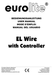
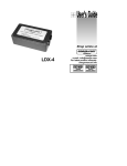
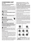
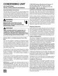
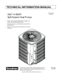
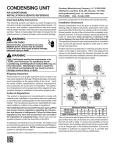
INSTALLATION & OPERATING
INSTRUCTIONS for
SPLIT SYSTEM
CONDENSING UNITS
All information contained herein is subject to change without notice.
I0-101G
Goodman Manufacturing Company, L.P.
2550 North Loop West, Suite 400, Houston, TX 77092
www.goodmanmfg.com
© 2003-2004 Goodman Manufacturing Company, L.P.
06/04
INDEX
company. Check the unit model number, specifications,
electrical characteristics and accessories to determine if
they are correct. In the event an incorrect unit is shipped,
it must be returned to the supplier and must NOT be
installed. The manufacturer assumes no responsibility for
installation of incorrectly shipped units.
Important Message to Homeowner ...................... 2
Codes and Regulations ....................................... 2
Inspection ............................................................ 2
Replacement Parts .............................................. 2
REPLACEMENT PARTS
Order all replacement parts through your local distributor.
When ordering parts, give complete model and serial
number as shown on the unit’s rating plate. Replacement
parts for this appliance are available through your
contractor or local distributor. For the location of your
nearest distributor consult the white business pages, the
yellow page section of the local telephone book or contact:
Important Safety Instructions ............................... 2
Clearances and Accessibility ............................... 2
Location ............................................................... 3
Electrical .............................................................. 3
Refrigerant Tubing ............................................... 4
Evaporator Coils .................................................. 4
SERVICE PARTS DEPARTMENT
GOODMAN MANUFACTURING COMPANY, L.P.
2550 NORTH LOOP WEST, SUITE 400
HOUSTON, TEXAS 77092
(713) 861 – 2500
Quick Connect Coils ............................................ 4
System Start Up .................................................. 4
Processing Checks .............................................. 4
Charge Checks .................................................... 5
IMPORTANT SAFETY INSTRUCTIONS
Recognize Safety Symbols, Words, and Labels
The following symbols and labels are used throughout this
manual to indicate immediate or potential hazards. It is
the owner’s and installer’s responsibility to read and
comply with all safety information and instructions
accompanying these symbols. Failure to heed safety
information increases the risk of property damage and/or
product damage, serious personal injury or death.
Superheat Determination ..................................... 5
Expansion Valve System ..................................... 5
Wiring Diagrams .................................................. 6
IMPORTANT MESSAGE TO OWNER
These instructions should be carefully read and kept near
product, for future reference. While these instructions are
addressed primarily to the installer, useful maintenance
information is included. Have your installing dealer
acquaint you with the operating characteristics of the
product and periodic maintenance requirements.
DANGER
IMMEDIATE HAZARDS WHICH WILL RESULT IN
PROPERTY DAMAGE, PRODUCT DAMAGE, SEVERE
PERSONAL INJURY AND/OR DEATH.
CODES AND REGULATIONS
This product is designed and manufactured to permit
installation in accordance with National Codes. It is the
installers responsibility to install the product in accordance
with National Codes and/or prevailing local codes and
regulations. The manufacturer assumes no responsibility
for equipment installed in violation of any code or
regulations.
WARNING
HAZARDS OR UNSAFE PRACTICES COULD RESULT
IN PROPERTY DAMAGE, PRODUCT DAMAGE,
SEVERE PERSONAL INJURY AND/OR DEATH.
CAUTION
Important: The United States Environmental Protection
Agency (EPA) has issued various regulations regarding
the introduction and disposal of refrigerants in this unit.
Failure to follow these regulations may harm the
environment and can lead to the imposition of
substantial fines. Because regulations may vary due
to passage of new laws, we suggest a certified
technician perform any work done on this unit. Should
you have any questions please contact the local office
of the EPA.
HAZARDS OR UNSAFE PRACTICES WHICH MAY
RESULT IN PROPERTY DAMAGE, PRODUCT
DAMAGE, AND/OR PERSONAL INJURY.
CLEARANCES AND ACCESSIBILITY
The condensing unit is designed to be located outside the
building with unobstructed condenser air inlet and
discharge. Additionally, the unit must be situated to permit
access for service and installation. Condenser air enters
from three sides. Air discharges upward from the top of
the unit. Refrigerant tube electrical connections are made
on the right side of the unit as you face the compressor
compartment. The best and most common application is
for the unit to be located 10” from the back wall with the
connection side facing the wall. Refer to Figures 1 and 2.
INSPECTION
Upon receiving the unit, inspect it for damage from
shipment. Claims for damage, either shipping or
concealed, should be filed immediately with the shipping
IO-101G
2
06/04
Close to the wall application assures free, unobstructed
air to the other two sides. In more confined application
spaces, such as corners, provide a minimum 10” clearance
on all air inlet sides. Allow 18” minimum for service access
to the compressor compartment and controls.
This “close to the wall” application minimizes exposed
tubing and wiring and reduces the space for children to
run around the unit. This will help to avoid possible
damage to the tubes or wiring and/or personal injury.
The top of the unit should be completely unobstructed. If
units are to be located under an overhang, there should
be a minimum of 36” clearance and provisions made to
deflect the warm discharge air out from the overhang.
10" Min.
Service Access
18" Min.
LOCATION
If unit is to be located under an overhang, there should be
a minimum of 36” clearance and provisions made to deflect
the water discharge air out from the overhang. If the
outdoor unit is mounted above the air handler, the
maximum lift should not exceed 70’ (suction line). If air
handler is mounted above condensing unit, the lift should
not exceed 50’ (liquid line.). Refer to Figure 3 and Table 1
for maximum refrigerant line lenghts.
10" Min.
OUTDOOR UNIT
PITCH SUCTION LINE TOWARD OUTDOOR
UNIT 1/2" FOR EVERY 10' OF LINE
Service Access
18" Min.
INDOOR UNIT ABOVE OR
LEVEL TO OUTDOOR UNIT
INDOOR UNIT
10"
LIQUID LINE
OUTDOOR UNIT
10"
ADDITIONAL SUCTION LINE OIL TRA P
FOR EA CH 20' RISE OF PIPE
70' MAX.
LIQUID LINE
SUCTION LINE OIL TRA PS
WHEN INDOOR UNIT IS 4
FEET OR MORE BELOW
OUTDOOR UNIT
INDOOR UNIT
INDOOR UNIT BELOW
OUTDOOR UNIT
FIGURE 1
8'
INVERTED LOOP
INDOOR UNIT
OUTDOOR UNIT
LIQUID LINE
50' MAX.
SUCTION LINE
10" Min.
FIGURE 3
Service Access
18" Min.
Cond
Unit
Tons
1 1/2
2
2 1/2
3
3 1/2
4
5
10" Min.
10" .
REFRIGERANT LINE LENGTH (Ft)
0-24
25-49
50-74***
Line Diameter (In. OD)
Suct
Liq
Suct
Liq
Suct
Liq
5/8
3/4
3/4
3/4
3/4
7/8
7/8
1/4
3/8
3/8
3/8
3/8
3/8
3/8
3/4
3/4
3/4*
3/4**
7/8***
1 1/8
1 1/8
3/8
3/8
3/8
3/8
3/8
3/8
3/8
3/4
3/4
7/8
7/8
1 1/8
1 1/8
1 1/8
3/8
3/8
1/2
1/2
1/2
1/2
1/2
* 7/8" required for full ratings
** 1 1/8" required for full ratings
Service Access
18" Min.
TABLE 1
10" .
The condensing unit must be mounted on a solid, level
foundation, i.e. pre-formed concrete slab or other suitable
base. For rooftop application, make sure the building
construction can support the weight and that proper
FIGURE 2
IO-101G
3
06/04
consideration is given the weather-tight integrity of the roof.
The condensing unit contains moving components and can
vibrate; therefore, sound is also a consideration in rooftop
application. Since this unit discharges warm condenser
air from the top with cooler air being drawn in three sides,
plantings can be made in relatively close proximity to the
unit. Owners should be advised to avoid lawn mower
discharge toward the unit depositing debris on the fan coil
surface reducing product efficiency.
Field Connection to the Valve and Valve Opening
1. Tubing should be cut square. Make sure it is round
and free of burrs at the connecting ends. Clean the
tubing to prevent contaminants from entering the
system.
2. Wrap a wet rag around the copper valve stub before
brazing.
3. Braze or silver solder the joint.
4. After brazing, quench with a wet rag to cool the joint.
Evacuate and charge the connecting lines as outlined
in these instructions.
5. Remove valve top cap. It is important to keep the cap
in a clean area to assure proper sealing once replaced.
6. Using a standard L shaped Allen wrench, break open
the valve body. To expedite opening the valve body
after it is broken, use a ratchet wrench with a short
Allen stub. Please note that it is normal to see oil on
the valve stem body once the cap is removed.
7. Replace the valve cap and tighten with a wrench
making sure that the the cap is sealed.
ELECTRICAL
Electrical installation will consist of power supply wiring to
the condensing unit as well as control wiring between
thermostat, indoor unit and the condensing unit as shown
on wiring diagram. All wiring must be in accordance with
National Electrical Code and/or local codes that may apply.
The condensing unit rating plate and the table inside the
front cover of this instruction lists pertinent electrical data
necessary for the selection of proper size electrical service
and over-current protection. The owner should be made
familiar with the location of the over-current protection,
the proper size for this application and the proper
procedure for disconnecting power service to the unit.
QUICK CONNECT COILS
Precharged System Installation
Installation procedure will differ when condensing units
are provided for use with precharged refrigerant coils and
lines. Condensing units are provided with #6 and #11
male quick connects instead of liquid and suction valves
attached to cabinet to contain the R-22 charge that is
sufficient for matching evaporator coils and 15’ of
interconnecting lines.
The condensing unit control wiring requires a 24 Volt
minimum 25 VA service from the indoor transformer as
shown on the wiring diagram.
REFRIGERANT TUBING
Use only refrigerant grade (dehydrated and sealed) copper
tubing of the size indicated in Table 1 to interconnect the
condensing unit with the indoor evaporator. Take extreme
care to keep the refrigerant tubing clean and dry prior to
and during installation.
Coils are provided with #6 and #11 male quick connects.
Line sets are required with #6 and #11 female quick
connects on both ends. Access ports are required in the
fittings of both liquid and suction lines at condenser end.
Both coil and line sets include R-22 holding charge only.
1. Connect lines to evaporator coil before connecting to
the condensing unit locating access ports adjacent to
condensing unit.
a. Form tubing so it properly aligns with the coil
connections.
b. Remove plugs and caps from connections.
c. Check to be sure mating surfaces are clean.
d. Lubricate rubber seal with clean refrigerant oil and
thread couplings together by hand to be sure they are
not cross threaded.
e. Tighten connections using backup wrench on
stationary fitting until coupling bottoms; then tighten
1/6 turn to complete knife edge seal.
2. Connect lines to condensing unit in the same manner
as to evaporator coil. Observe same precautions.
3. After making all connections and opening valves,
check all piping for leaks.
Do not remove plugs from ends of tubing until connection
is ready to be made. Suction line insulation is necessary
to prevent condensation from forming on and dropping
from suction line. Generally 3/8" wall thickness of Armflex
or equivalent is satisfactory. In severe application (hot, high
humidity areas) greater thickness may be required. Apply
suction line insulation by sliding it on the sealed tubing
before cutting and making connections.
EVAPORATOR COILS
WARNING
USE EXTREME CARE IN REMOVING THE CAPS
FROM THE SUCTION AND LIQUID LINE FITTINGS
AS THERE IS PRESSURE PRESENT. A FITTING IS
ON THE LIQUID LINE TO REMOVE PRESSURE.
WARNING
DO NOT REMOVE PROTECTIVE CAPS UNTIL
INSTALLATION HAS BEEN COMPLETED AND FINAL
CONNECTIONS ARE TO BE MADE.
IO-101G
SYSTEM START UP
Processing Checks
Condensing units are supplied R-22 charge sufficient for
typical matching evaporator and approximately 15’ of
interconnecting tubing. Condensing unit liquid and suction
valves are closed to contain the charge within the unit.
4
06/04
The recommended procedure for processing and charge
adjustment is as follows:
1. Connect vacuum pump to both base valve service
ports.
2. Evacuate tubing and evaporator through liquid and
suction base valve ports, to 500 microns or less for a
minimum of 30 minutes. Close valve to pump and
wait 15 minutes. Vacuum should not rise above 800
microns. If unable to obtain 500 micorns, or vacuum
rises above 800 microns over a 15 minute period,
discontinue evacuation, pressurize and check for
leaks. Repair any leaks found and repeat step 2.
3. Close valve to vacuum pump and stop pump. Break
vacuum by opening liquid and suction base valves.
Fully open base valves and remove pump lines.
Connect service gauges making sure lines are purged.
4. Set thermostat system switch to “COOL” and
temperature to highest setting. Close all disconnects.
5. Set thermostat to call for cooling. Check for operation
of indoor and outdoor fans. Allow for at least 10
minutes.
6. Check charge and adjust if necessary. Refer to
appropriate “Check Charge” section.
Superheat Determination
1. Read suction pressure. Using Table 3, determine
saturated suction temperature.
2. Read suction line temperature.
3. Use the following formula to determine superheat:
Charge Checks
Capillary Tube/Fixed Orifice System
1. Fully open both base valves.
2. Connect service gauge manifold to base-valve service
ports being sure to purge lines. Run system at least
10 minutes to allow pressure to stabilize.
3. Temporarily install thermometer on suction (large) line
near condensing unit. Be sure of good contact
between the thermometer and line. Wrap thermometer
with insulating material to assure accurate reading.
4. Refer to Table 2 for proper system superheat. Add
charge to lower superheat. Remove charge to raise
superheat.
5. Remove gauge lines carefully.
Expansion Valve System
1. Fully open both base valves.
2. Connect service gauge manifold to base-valve service
parts making sure lines are purged. Run system at
least 10 minutes to allow pressure to stabalize.
3. Temporarily install the thermometer to liquid (small)
line near condensing unit. Be sure that the contact
between thermometer and line is good. Wrap
thermometer with insulating material to ensure
accurate reading.
4. Referring to Table 4, adjust charge to obtain a
temperature 12-15°F below the saturated liquid
temperature.
Superheat = Suction Line Temp. - Saturated Suction Temp.
SATURATED SUCTION PRESSURE (R-22)
SUCTION
PRESSURE PSIG
50
53
55
58
61
63
66
69
72
75
78
81
TABLE 3
Example:
If the Liquid Pressure is 260 PSIG then the Saturated
Temperature will be 120°F. Adjust the Saturated
Temperature by subtracting 12-15°F. This will give you a
Liquid Line Temperature of 105° - 108°F.
WARNING
ESCAPING LIQUID REFRIGERANT CAN CAUSE
BURNS.
SATURATED LIQUID TEMPERATURE
SYSTEM SUPERHEAT
AMBIENT CONDENSER
RETURN AIR TEMPERATURE
INLET TEMPERATURE
( °F DRYBULB)
°F DRYBULB
65
70
75
80
85
100
95
90
85
80
75
70
65
60
5
5
13
17
5
5
10
14
19
25
5
7
10
12
17
20
26
30
5
5
12
17
21
25
28
32
33
SATURATED SUCTION
TEMPERATURE °F
26
28
30
32
34
36
38
40
42
44
46
48
LIQUID PRESSURE
(PSIG)
200
210
220
230
240
250
260
270
280
290
300
5
5
18
20
26
29
32
35
37
SATURATED
TEMPERATURE °F
102
105
108
111
114
117
120
123
126
128
131
TABLE 4
TABLE 2
IO-101G
5
06/04
NOTE: System with over 50’ separation between
condensing unit and evaporator may require oil charge
adjustment.
SPECIAL NOTE: Systems with MORE than 15’ of
interconnecting tubing, please refer to Table 5 for line
charge allowance per foot of tubing.
LINE CHARGE ALLOWANCE (R-22) (oz./ft.)
LINE
O. D. (IN)
LIQUID
LINE
1/4
3/8
1/2
5/8
3/4
7/8
1 1/8
1 3/8
0.22
0.58
1.14
1.86
OIL CHARGE ADJUSTMENT
SUCTION
LINE
UNIT MODEL
(TONS)
ADDITIONAL OIL CHARGE PER EACH
ADDITIONAL 10' OF LINE (OZ.)*
1 - 1 1/2
2-5
0.25
0.5
*Use either Texaco WF-32 (formerly cappella B)
or Suniso 3G-S oil
0.04
0.06
0.08
0.15
0.22
TABLE 6
TABLE 5
IO-101G
6
06/04
WIRING DIAGRAMS
ALT. DOUBLE
POLE CONTACTOR
OUTDOOR CONTROL BOX
OUTDOOR POWER SUPPLY
PU
T1
R
C
T2
R
F
HERM
Y
R
BK
Y
BK
BR
COMPRESSOR/FAN
L1
R
R
CAPACITOR
T1
T2
PU
L1
L2
COMPRESSOR
MOTOR
Y
START ASSIST
(IF USED)
PU
(START ASSIST
IF USED)
C
COMPRESSOR
INTERNAL
OVERLOAD
S
USE L1 FOR
NEUTRAL OR
GROUNDED SUPPLY
IF USED
START ASSIST
L1 C
O
N
T
A
C
T
O
T1 R
(IF USED)
R
OUTDOOR POWER
SUPPLY - (SEE
UNIT RATING
PLATE)
USE COPPER
CONDUCTORS ONLY
Y
FAN MOTOR
L2
CRANKCASE HEATER
C L2
O
N
T
A
C
T
O T2
R
EQUIPMENT GROUND
FAN MOTOR
CAPACITOR
PU
COMPRESSOR
BK
C
BR
CONNECT TO APPROP.
CONTROL CIRCUIT HAVING
MIN. 40 VA 24 VOLT
N.E.C. CLASS 2
TRANSFORMER OR FOR
CERTIFIED C.S.A.
INSTALLATION. USE C.S.A.
CERTIFIED ENERGY LIMITED
CLASS 2 TRANSFORMER.
BK
S
BK
Y
PU
R
CONTACTOR
ON
COIL
THERMOSTAT
FAN SWITCH
R
G
AUTO
BK
BK
THERMOSTAT
BK
COOL
FAN RELAY
ANTICIPATOR
CRANKCASE HEATER IF USED
COIL
Y
COOL
R
COLOR CODE
THERMOSTAT
WIRING FOR
FACTORY
OPTIONS
FIELD
WIRING
FACTORY
WIRING
WIRING CODE
HIGH VOLTAGE
LOW VOLTAGE
WIRE NUT
OPTIONAL START ASSIST
BK
BLACK
R
RED
Y
YELLOW
BL
BLUE
PU
LTBL
PURPLE
LIGHT BLUE
BR
BROWN
G
GREEN
OFF
THERMOSTAT
SYSTEM
SWITCH
BULB
HEAT
COIL
THERMOSTAT
ADJ. HEAT
ANTICIPATOR
W
24V
R
C
LOW VOLTAGE
TRANSFORMER
NOTES:
REPLACEMENT WIRE MUST BE SAME
INDOOR POWER SUPPLY
GAGE AND INSULATION THICKNESS,
105° C APPLIANCE WIRING MATERIAL.
3/98 REV. A
B17784-01
SINGLE PHASE
OUTDOOR POWER SUPPLY
HP
BL
Y
V
CH
BR
L2
L3
Y
V
L1
L1
R
BK
C
C
C
C
BK
R
V
BR
V
R
BL
CONNECT TO APPROP. CONTROL CIRCUIT HAVING
MIN. 40 VA. 24 VOLT N.E.C. CALSS 2
TRAMSFORMER OR FOR CERTIFIED C.S.A
INSTALLATION. USE C.S.A. CERTIFIED ENERGY
LIMITED CLASS 2 TRANSFORMER.
Y
T1
T2
T3
L1
L2
L3
T3
T1
T2
T1
2
C
FC
EQUIPMENT GROUND USE
COPPER CONDUCTORS ONLY
3
1
COMP
CAP
MOTOR
BK
POWER SUPPLY
(SEE RATING PLATE)
USE COPPER CONDUCTORS ONLY
BK
ON
THERMOSTAT
FAN SWITCH
MAIN
Y
G
S
CONTACTOR
COIL
AUTO
HP
V
AUX
THERMOSTAT
COOL
ANTICIPATOR
BR
CM
BK
FAN RELAY
COIL
Y
IO
BK
BK
C
COMP
COOL
R
R
THERMOSTAT
BULB
R
OFF
THERMOSTAT
SYSTEM
SWITCH
BK
HEAT
COIL
THERMOSTAT
ADJ. HEAT
ANTICIPATOR
CH
W
24V
R
C
LOW VOLTAGE
TRANSFORMER
COMPONENT CODE
CM
OUTDOOR FAN MOTOR
COLOR CODE
COMP
COMPRESSOR
C
CONTACTOR
DEFROST CONTROL
BK
BLACK
LOW VOLTAGE DEFROST RELAY
R
RED
INDOOR POWER SUPPLY
DC
LDVR
CH
IO
LP
HP
OT
WIRING CODE
FACTORY WIRING
HIGH VOLTAGE
FIELD WIRING
CRANKCASE HEATER
INTERNAL OVERLOAD
LOW PRESSURE CONTROL
HIGH PRESSURE CONTROL
OUTDOOR THERMOSTAT (OPTIONAL)
FC
DFT
FAN CAPACITOR
DEFROST THERMOSTAT
RVC
HVDR
REVERSING VALVE COIL
HIGH VOLTAGE DEFROST RELAY
LOW VOLTAGE
WIRE NUT
LINE SPLICE
Y
YELLOW
BL
BLUE
V
VIOLET
LTBL
LIGHT BLUE
BR
BROWN
G
GREEN
O
ORANGE
W
CONTROLS SHOWN WITH UTILITIES IN 'ON'POSITION
AND THERMOSTAT IN 'OFF' POSITION.
WHITE
NOTES:
1) TO INDOOR UNIT LOW
VOLTAGE TERMINAL BLOCK &
INDOOR THERMOSTAT.
2) SEE INDOOR UNIT &
OUTDOOR UNIT INSTALLATION
INSTRUCTIONS FOR CONNECTION
OF OPTIONAL OUTDOOR THERMOSTAT.
USE N.E.C. CLASS 2 WIRE
07/97 REV. D
B17783-00
THREE PHASE
IO-101G
7
06/04
NOTE: SPECIFICATIONS AND PERFORMANCE DATA LISTED HEREIN
ARE SUBJECT TO CHANGE WITHOUT NOTICE
Quality Makes the Difference!
All of our systems are designed and manufactured with the same high quality standards regardless of size or
efficiency. We have designed these units to significantly reduce the most frequent causes of product failure.
They are simple to service and forgiving to operate. We use quality materials and components. Finally, every
unit is run tested before it leaves the factory. That’s why we know. . .There’s No Better Quality.
Visit our website at www.goodmanmfg.com for information on:
• Goodman products
• Warranties
• Customer Services
• Parts
• Contractor Programs and Training
• Financing Options
© 2003-2004 Goodman Manufacturing Company, L.P.
IO-101G
8
06/04