1
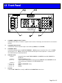
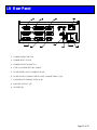
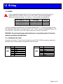
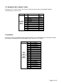
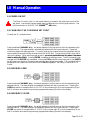
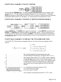
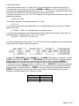
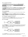
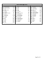
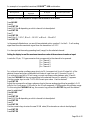
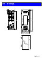
TELEDYNE HASTINGS INSTRUMENTS INSTRUCTION MANUAL PowerPod 400 Power Supply/Totalizer Manual Print History The print history shown below lists the printing dates of all revisions and addenda created for this manual. The revision level letter increases alphabetically as the manual undergoes subsequent updates. Addenda, which are released between revisions, contain important change information that the user should incorporate immediately into the manual. Addenda are numbered sequentially. When a new revision is created, all addenda associated with the previous revision of the manual are incorporated into the new revision of the manual. Each new revision includes a revised copy of this print history page. Revision A (Document Number 164-012005).................................................................................. January 2005 Revision B (Document Number 164-022005 ................................................................................ February 2005 Revision C (Document Number 164-062005 ....................................................................................... June 2005 Revision D (Document Number 164-082005 ................................................................................... August 2005 Revision E (Document Number 164-102005 .................................................................................. October 2005 Revision F (Document Number 164-012006)................................................................................... January 2006 Revision G (Document Number 164-092006)……………………………………………………… September 2006 Revision G (Document Number 164-112006)……………………………………………………… November 2006 Visit www.teledyne-hi.com for WEEE disposal guidance. Hastings Instruments reserves the right to change or modify the design of its equipment without any obligation to provide notification of change or intent to change. Page 2 of 42 Table of Contents 1.0 QUICK START INSTRUCTIONS. . . . . . . . . . . . . . . . . . . . . . . . . . . . . . . . . . . . . . . . . . . . . . . . . . . . . . . . . . . . . . . . . . . . . . . . . . . . . . . . . . . 5 2.0 SAFETY. . . . . . . . . . . . . . . . . . . . . . . . . . . . . . . . . . . . . . . . . . . . . . . . . . . . . . . . . . . . . . . . . . . . . . . . . . . . . . . . . . . . . . . . . . . . . . . . . . . . . . . . . . . . . . . . . . 6 3.0 FEATURES. . . . . . . . . . . . . . . . . . . . . . . . . . . . . . . . . . . . . . . . . . . . . . . . . . . . . . . . . . . . . . . . . . . . . . . . . . . . . . . . . . . . . . . . . . . . . . . . . . . . . . . . . . . . . . 7 4.0 SPECIFICATIONS . . . . . . . . . . . . . . . . . . . . . . . . . . . . . . . . . . . . . . . . . . . . . . . . . . . . . . . . . . . . . . . . . . . . . . . . . . . . . . . . . . . . . . . . . . . . . . . . . . . . . 9 5.0 FRONT PANEL . . . . . . . . . . . . . . . . . . . . . . . . . . . . . . . . . . . . . . . . . . . . . . . . . . . . . . . . . . . . . . . . . . . . . . . . . . . . . . . . . . . . . . . . . . . . . . . . . . . . . . 10 6.0 REAR PANEL. . . . . . . . . . . . . . . . . . . . . . . . . . . . . . . . . . . . . . . . . . . . . . . . . . . . . . . . . . . . . . . . . . . . . . . . . . . . . . . . . . . . . . . . . . . . . . . . . . . . . . . . . 11 7.0 WIRING. . . . . . . . . . . . . . . . . . . . . . . . . . . . . . . . . . . . . . . . . . . . . . . . . . . . . . . . . . . . . . . . . . . . . . . . . . . . . . . . . . . . . . . . . . . . . . . . . . . . . . . . . . . . . . . . 12 7.1. 7.2. 7.3. 7.4. 7.5. 8.0 POWER ......................................................................................................................................... 12 COMMUNICATIONS ................................................................................................................... 12 TRANSDUCER CONNECTIONS ................................................................................................. 13 ALARMS ....................................................................................................................................... 13 ANALOG SIGNAL FOLLOWERS ................................................................................................. 14 MANUAL OPERATION. . . . . . . . . . . . . . . . . . . . . . . . . . . . . . . . . . . . . . . . . . . . . . . . . . . . . . . . . . . . . . . . . . . . . . . . . . . . . . . . . . . . . . . . . . . . . 15 8.1. 8.2. 8.3. 8.4. 8.5. 8.6. 8.7. 9.0 POWER ON/OFF ........................................................................................................................... 15 CHANGING THE COMMAND SET POINT ................................................................................. 15 OVERRIDE OPEN ......................................................................................................................... 15 OVERRIDE CLOSED .................................................................................................................... 15 SETTING A CHANNEL TO AUTO CONTROL ............................................................................ 16 SETTING A CHANNEL TO DIRECTLY METER INCOMING SIGNALS ..................................... 16 SETTING A CHANNEL TO DISPLAY THE TOTALIZER FUNCTION ........................................ 16 EXTERNAL/REMOTE OPERATION. . . . . . . . . . . . . . . . . . . . . . . . . . . . . . . . . . . . . . . . . . . . . . . . . . . . . . . . . . . . . . . . . . . . . . . . . . . . . 18 9.1. 9.2. 9.3. 10.0 SELECTING EXTERNAL/REMOTE OPERATION (FRONT PANEL O NLY)..................................... 18 CHOOSING RS-232 COMMUNICATION ..................................................................................... 18 CHOOSING RS-485 COMMUNICATION ..................................................................................... 18 SETUP/CAL MODE. . . . . . . . . . . . . . . . . . . . . . . . . . . . . . . . . . . . . . . . . . . . . . . . . . . . . . . . . . . . . . . . . . . . . . . . . . . . . . . . . . . . . . . . . . . . . . . . . . 19 10.1. 10.2. 10.2.1. 10.2.2. 10.2.3. 10.2.4. 10.2.5. 10.2.6. 10.3. 10.3.1. 10.3.2. 10.3.3. 10.4. 10.4.1. 10.4.2. 10.5. 10.5.1. ENTERING THE SETUP/CAL MODE .......................................................................................... 19 DISPLAY SETUP .......................................................................................................................... 19 BLANKING A DISPLAY LINE/CHANNEL .............................................................................................. 19 SELECTING DISPLAY BRIGHTNESS.................................................................................................... 19 SELECTING UNIT -OF-MEASURE........................................................................................................ 20 SELECTING GAS ID ......................................................................................................................... 20 SETTING A/D CONVERSION RATE (FILTER) ...................................................................................... 20 FRONT PANEL LOCK OUT................................................................................................................ 21 TOTALIZER SETUP ..................................................................................................................... 21 COUNT UP TO A SET POINT ............................................................................................................. 21 COUNT DOWN FROM A SET POINT ................................................................................................... 22 COUNT CONTINUOUSLY.................................................................................................................. 22 EXTERNAL COMMUNICATION SETUP .................................................................................... 22 RS-232 SETTINGS ........................................................................................................................... 22 RS-485 SETTINGS ........................................................................................................................... 22 SELECTING THE ANALOG SIGNAL LEVEL .............................................................................. 23 ZERO TO FIVE VOLT O PERATION...................................................................................................... 23 Page 3 of 42 10.5.2. ZERO TO TEN VOLT OPERATION...................................................................................................... 23 10.5.3. FOUR TO TWENTY MILLIAMP O PERATION ........................................................................................ 23 10.6. SETTING LIMIT ALARMS........................................................................................................... 24 10.6.1. SETTING A SINGLE CHANNEL ’S HIGH LIMIT...................................................................................... 24 10.6.2. SETTING A SINGLE CHANNEL ’S LOW LIMIT....................................................................................... 24 10.6.3. SETTING A SINGLE CHANNEL ’S HYSTERESIS ..................................................................................... 24 10.7. SETTING RATIO CONTROL PARAMETERS .............................................................................. 25 E NABLING RATIO CONTROL ........................................................................................................................ 25 10.8. CALIBRATING A CHANNEL TO ITS INCOMING SIGNALS ...................................................... 26 10.8.1. RESETTING THE ZERO O NLY............................................................................................................ 26 10.8.2. RESETTING THE SPAN O NLY............................................................................................................ 26 10.8.3. RESETTING ZERO AND SPAN ............................................................................................................ 27 10.8.4. SETTING A MULTIPLICATION FACTOR.............................................................................................. 27 10.9. SERIAL COMMUNICATION........................................................................................................ 28 10.9.1. COMMANDS .................................................................................................................................... 28 10.9.2. SET POINT Q UERIES ........................................................................................................................ 28 10.9.3. ALARM/FLAG Q UERIES .................................................................................................................... 28 11.0 APPENDIX A. . . . . . . . . . . . . . . . . . . . . . . . . . . . . . . . . . . . . . . . . . . . . . . . . . . . . . . . . . . . . . . . . . . . . . . . . . . . . . . . . . . . . . . . . . . . . . . . . . . . . . . . . . 30 12.0 APPENDIX B. . . . . . . . . . . . . . . . . . . . . . . . . . . . . . . . . . . . . . . . . . . . . . . . . . . . . . . . . . . . . . . . . . . . . . . . . . . . . . . . . . . . . . . . . . . . . . . . . . . . . . . . . . 33 13.0 APPENDIX C . . . . . . . . . . . . . . . . . . . . . . . . . . . . . . . . . . . . . . . . . . . . . . . . . . . . . . . . . . . . . . . . . . . . . . . . . . . . . . . . . . . . . . . . . . . . . . . . . . . . . . . . . 33 14.0 APPENDIX D . . . . . . . . . . . . . . . . . . . . . . . . . . . . . . . . . . . . . . . . . . . . . . . . . . . . . . . . . . . . . . . . . . . . . . . . . . . . . . . . . . . . . . . . . . . . . . . . . . . . . . . . . 36 15.0 DRAWINGS. . . . . . . . . . . . . . . . . . . . . . . . . . . . . . . . . . . . . . . . . . . . . . . . . . . . . . . . . . . . . . . . . . . . . . . . . . . . . . . . . . . . . . . . . . . . . . . . . . . . . . . . . . . 41 16.0 WARRANTY . . . . . . . . . . . . . . . . . . . . . . . . . . . . . . . . . . . . . . . . . . . . . . . . . . . . . . . . . . . . . . . . . . . . . . . . . . . . . . . . . . . . . . . . . . . . . . . . . . . . . . . . . . 42 16.1. 16.2. WARRANTY REPAIR POLICY ............................................................................................................. 42 NON-WARRANTY REPAIR POLICY..................................................................................................... 42 Page 4 of 42 1.0 Quick Start Instructions Important – The PowerPod -400 comes calibrated from the factory according to your specifications. No set up is necessary unless you need to change the specs 1ea 1ea 1ea 1ea 1ea PowerPod-400 AC power cord 15-pin, Hi Density, D-style connector 9-pin, D-style connector user’s manual When unpacking the PowerPod, the package will contain everything you need. J-1 Ch1 5 Signal common J-2 Ch2 6 Analog signal J-3 Ch3 7 Case ground J-4 Ch4 8 Override Control J-5 Analog out 9 -15 VDC J-6 RS-232 10 NC J-7 RS-485 11 +15 VDC J-8 Alarms 12 Valve return J-9 RS-485 14 Set point (in) Pin-outs Connect a “known good” transducer to the desired channel (See next frame for pin-outs) 1) Check power setting switch on the back panel and make sure it is set appropriately. 2) Ensure the power switch is off, and then connect the power cord. OPEN 1 CLOSE 2 CLOSE 3 CLOSE 4 CLOSE OPEN OPEN OPEN 1 2 3 4 5 6 7 8 9 0 . HASTINGS 1) Press the desired Channel # Key. Press the Auto key. Turn power switch to on position. If you have just turned on the mass flow instrument and the power, some settling is necessary. (For Controllers) 2) Press the desired Channel # Key. Enter desired flow. Press the enter key. Page 5 of 42 2.0 Safety Read this manual in its entirety before operating the POWERPOD-400 Power Supply/Totalizer. The POWER POD-400 is designed to operate with most Teledyne Hastings Instruments (THI) flow controllers and meters. Read all wiring and power hookup instructions and understand the requirements prior to using another manufacturer’s products with the POWER POD-400. Insure that any product being interfaced with the POWER POD-400 is wired according to prevailing local safety and operational standards before operating. The following symbols and terms may be found on THI products and/or in THI manuals and indicate important information. When found on the device, this symbol indicates that the operator should refer to the manual for important instructions on the proper use of this device. When found in the manual, this symbol indicates that the reader should understand the implications contained in the text before operating the device. This symbol indicates that a shock hazard may be present. Read the instruction manual carefully and insure that the device is wired properly and that all settings have been checked prior to applying power to the device. The WARNING label indicates important information that should be heeded for safe and proper performance of the device. The label, CAUTION , is used to indicate that damage to the power supply or equipment connected to it could occur if directions are not followed. Warranty could be invalidated if the instructions in this manual are not followed. Page 6 of 42 3.0 Features The POWER POD-400 serves as a convenient control center that can be rack-mounted using standard halfrack hardware or can be used as a bench top unit. The POWER POD-400 is equipped with a 4 X 20 character, vacuum fluorescent display (VFD). The display emulates a liquid crystal display in its command structure but the VFD gives the unit a greater viewing angle and better visibility than available with most conventional LED or LCD displays. The display can be set to four different brightness levels. Use a lower brightness setting to extend the already long expected life time of the display. Use brighter settings for viewing areas where ambient light may be too bright or cause glare, or where greater viewing distances are required. Most features are accessible via the membrane keys on the front panel. Consult the section on each function to check its availability. Operators are guided through the many features and options by selecting their choices from an intuitive menu structure. FRONT PANEL LOCKOUT The Front Panel Lockout function is only available through serial communication. Manual Overrides remain available during Lockout via a minimum number of keystrokes using dedicated keys for this purpose and allow any command setting to be overridden in either the high (open) or low (closed) state. ANALOG RANGE SELECTION Analog signal and control ranges are operator selectable. The operator can choose between three different DC ranges: 0 -5 VDC, 0-10 VDC or 4 -20 mA. A fifteen (15) pin, high density, sub-miniature, D-type connector is provided for separate monitoring of each channel’s analog transducer signal. CAUTION: Consult the appropriate section for limits to the loading of these signals. SERIAL COMMUNICATION The POWERPOD -400 comes equipped with standard RS-232 and RS-485, serial communication. Most functions, features, signals and alarms are accessible and modifiable via any remote computer. The following commands are manual commands only: OPEN, AUTO and CLOSE. The status of these settings can be read via serial communication but they cannot be changed except manually, from the front panel. Page 7 of 42 POWER SELECTION Power input is switchable between 100 VAC, 115 VAC and 230VAC (50 or 60 Hz) via the rear panel. For the safety of the operator as well as the device, the correct power level should be selected prior to connecting to the power mains. See the table “POWERPOD-400 Specifications” in section 3.0 for the proper fusing when changing power settings. RATIO CONTROL Ratio control is possible between channels using a familiar master/slave configuration. Channel one (1) must be enabled as the master channel. Any combination of the remaining channels is possible for slave channel assignment. TOTALIZER A Totalizer function is present for each channel with the capability of counting down from a set point, counting up to a set point or continuous count up. The maximum count is ±999999 units. When the set points are reached, a memory flag for each set point is set to a digital ‘1’ indicating a Boolean ‘true’ value. The Totalizer set point flags must be polled via digital communication to be read. Each flow channel has one low-limit and one high-limit set point available. These alarms are available via open-collector, opto-isolated outputs on the rear panel as well as serial communication. POWER OUTAGES AND THE OVERRIDE CONDITION In the event of a power outage, even one of short duration, the POWER POD-400 is designed to conduct a software reset. During the period of time in which the reset is occurring, it will not accept or respond to any commands either manually or digitally until the reset process is completed. After said reset, the POWER POD-400 will have remembered all previously entered set-points but all channels are designed to come up in the “Override-CLOSEd” condition. For meters, this should have no affect on their behavior. All analog-only, THI, flow controllers with normally-closed (NC) valves will close and remain closed until operator intervention manually returns selected channels’ Override condition back to the AUTO mode. For all other controllers, this means that the control signal (pins 5 to 14) of J1 through J4 will return to the previously set level. For controllers not taking advantage of the Override function (pin 8), these controllers will return to their normal, preset operating condition unless other intermediary steps are undertaken. Controllers that are making use of the override function (Pin 8) and have normally-open valves will be driven to the fully open condition. Page 8 of 42 4.0 Specifications Specification Power Inputs PowerPod-400 Specifications Table V P f Transducer Number Channels VSupply ISupply I/O Value 100 115 230 68 50 -60 4 ±15 ±250 0-5 0 - 10 4 - 20 Units VAC Notes 0.7 A, 250VAC, SB Fuse 0.6 A, 250VAC, SB Fuse 0.315 A, 250VAC, SB Fuse VA Hz VDC mA Bi-polar Bi-polar VDC mADC Display Vacuum Fluorescent, LCD Emulator Type # Lines # Characters Brightness Levels A/D Converter Filtering Rate Alarms 3 per channel Dimensions Front Panel (h x w) Case (h x w x d) Hole Centers (h x w) Weight 4 20 4 4, 15, 30, 100 Hz 1 High 1 Low 1 Total 3.5 x 9.5 3 x 8 x 9.5 3 x 8.825 in in in 5 1/4 lbs Page 9 of 42 5.0 Front Panel OPEN 1 CLOSE 2 CLOSE 3 CLOSE 4 CLOSE OPEN OPEN OPEN 400 1 2 3 4 5 6 7 8 9 0 . HASTINGS 1. CHANNEL NUMBER SELECT KEYS Selects channel for editing. An asterisk (*) appears in the first column of the display to indicate that this is the channel to be edited. 2. OVERRIDE INDICATORS Indicates when a channel’s command signal is overridden high (OPEN) or low (CLOSED). 3. OVERRIDE KEYS Override the command signal on the ACTIVE CHANNEL . OPEN sets control override (pin 8) to +15V. CLOSED sets command to –15V. AUTO allows the user to set the command signal for normal operation. A channel must be active before these keys can become operational. 4. DISPLAY AREA Column 1: Column 2: Col’s 3 – 8: Column 9: Col’s 10 – 14: Column 15: Col’s 16 – 20: 5. Reserved for displaying ACTIVE CHANNEL (*), MASTER channel (M), SLAVE (S) or TOTAL (T). Reserved for polarity indicator. Signal monitor. Displays current input signal while in METER mode, AVERAGE while set to average readings or TOTAL while in TOTALIZER mode. Space UNITS OF MEASURE display. Space GAS ID. KEYPAD Use to enter SET POINTS or to modify the SETUP or CALIBRATION of control unit. Page 10 of 42 6.0 Rear Panel 1. POWER ON/OFF SWITCH 2. POWER INLET & FUSE 3. POWER SELECTOR SWITCH 4. FUSE Vs. POWER SETTING TABLE 5. RS-232 SERIAL PORT CONNECTOR (J6) 6. RS-485, DAISY CHAINED, SERIAL PORT CONNECTORS (J7, J9) 7. TRANSDUCER CONNECTORS (J1-J4) 8. ANALOG OUTPUT (J5) 9. ALARMS (J8) Page 11 of 42 7.0 Wiring 7.1. POWER Power is supplied through a fused, AC jack on the rear panel (item 2).Use the power cord supplied with the unit (PN15-17-011 for 115 VAC, 60Hz). See the following table for selecting the proper fuse rating. Use a metric, 5 x 20 mm sized, time-delayed fuse. Power Setting (50 – 60 Hz) 100 VAC 115 VAC 230 VAC Fuse Rating 0.315 Amp/250 VAC 0.60 Amp/250 VAC 0.70 Amp/250 VAC THI P/N 23-05-038 23-05-039 23-05-040 Cords without plugs are supplied with units shipped outside of the U.S. Consult and comply with any local laws and/or codes when connecting to any AC main. The AC input is user selectable between 100, 115 or 230 VAC, 50 or 60 Hz, via an AC selector switch next to the AC jack (Item 3). WARNING: Be sure to set the power select switch prior to connecting to mains. Re-fuse the connector according to the table above. 7.2. COMMUNICATIONS Connectors J6 (Item 4), J7 (Item 6) and J9 (Item 6) are for RS-232, RS-485 connections respectively. Settings for serial communication are accessible via the front panel. J6 RS-232 (DB-9) 1 2 3 4 5 6 7 8 9 Unused Tx Rx Unused Gnd Unused RTS CTS Unused J7, J9 RS-485 (DB-9) 1 2 3 4 5 6 7 8 9 Unused RxTx+ Unused/Gnd (Gnd) Unused Gnd/VCC (VCC) R+ TUnused Page 12 of 42 7.3. TRANSDUCER CONNECTIONS Connector s J1, 2, 3 and 4 (Item 7) are 15 pin D style connectors wired in the standard Hastings Instruments pin-out (H pin-out). J1, J2, J3, J4 Transducer Connectors (DB-15) (H-Pinout) 1 2 NC NC 3 4 5 6 7 8 9 10 11 12 13 14 15 NC NC Sig. Com. Sig. In Case Gnd. Cntrl Over-ride -15 VDC NC +15 VDC Valve Return NC Set Point Out +5 VDC Ref. Valve Cntrl Voltage mA Sig mA Sig 1.5mA Ext-In Not Used. 7.4. ALARMS Connector J8 (item 9) provides the user with open-collector, opto-isolated alarms for individual channels. Each channel is provided with one user settable “High” and one “Low” alarm. J8 Open Collector, OptoIsolated, High & Low Alarms (HD DB-26) 1 2 3 4 5 6 7 8 9 10 11 12 13 14 15 16 17 18 19 20 21 22 23 24 25 26 Chnl 1, High Alarm Chnl 1, Low Alarm Chnl 1, Alarm Return Chnl 2, High Alarm Chnl 2, Low Alarm Chnl 2, Alarm Return NC NC NC NC NC NC NC NC NC NC NC NC Chnl 3, High Alarm Chnl 3, Low Alarm Chnl 3, Alarm Return Chnl 4, High Alarm Chnl 4, Low Alarm Chnl 4, Alarm Return NC NC Page 13 of 42 7.5. ANALOG SIGNAL FOLLOWERS Analog signals from each channel’s transducers are available for reading or for sending to another power supply for ratio (Master/Slave) operation. The signal can be sent to a channel on another power supply and programmed as a Master for that power supply, allowing the remaining three channels to operate as slaves. When operating 4 – 20 mA instruments, the followers supply a 0 -10 volt signal. J5 Analog Out (HD DB-15) 1 2 3 4 5 6 7 8 9 10 11 12 13 14 15 Channel 1 Signal Channel 1 Return Channel 2 Signal Channel 2 Return Channel 3 Signal Channel 3 Return Channel 4 Signal Channe l 4 Return Page 14 of 42 8.0 Manual Operation 8.1. POWER ON/OFF The Power On switch, item 1 in rear panel drawing, is located in the upper right corner of the rear panel. Insure that the proper power setting is selected prior to turning the power on. See the Power section of WIRING THE POWER POD-400, above. 8.2. CHANGING THE COMMAND SET POINT Channel two (2) , example shown. Press the desired CHANNEL # key. An asterisk appears in the first space on the line representing the selected channel. The meter display is immediately replaced with the current set point. Pressing a number key begins the editing process. The cursor lands on the channel set point to be edited, and the new command is entered with the most sig nificant bit (MSB) first. The set point is filled in from left to right on the display. When entering a new set point, you must use the decimal key when it has been used in setting the SPAN. Pressing ENTER completes the editing process. The old command is not changed until the ENTER key is actuated. Hitting the ESCape button at any time prior to the ENTER key will return the display to its previous state without any changes being made. This command will not be applied to the output until the channel is set for AUTO operation. See Setting a Channel to AUTO Control. 8.3. OVERRIDE OPEN Press the desired CHANNEL # key. An asterisk appears in the first space on the line representing the selected channel. The meter display is immediately replaced with the current set point. Pressing the OPEN key results in the application of +15 VDC to pin number eight (8) of the corresponding 15 pin Sub-D connector and returns the previously programmed metering function to the display. 8.4. OVERRIDE CLOSED Press the desired CHANNEL # key. An asterisk appears in the first space on the line representing the selected channel. The meter display is immediately replaced with the current set point. Pressing the CLOSE key results in the application of -15 VDC to pin number eight (8) of the corresponding 15 pin Sub-D connector and returns the previously programmed metering function to the display. Page 15 of 42 8.5. SETTING A CHANNEL TO AUTO CONTROL Press the desired CHANNEL # key. An asterisk appears in the first space on the line representing the selected channel. The meter display is immediately replaced with the current set point. Pressing the AUTO key causes pin number eight (8) of the 15 pin Sub-D connector to float and returns the previously programmed metering function to the display. Pin 14 signal levels are now available for control. 8.6. SETTING A CHANNEL TO DIRECTLY METER INCOMING SIGNALS Press the MODE key. The MODE menu appears in the display. To select METER, press 1, and then ENTER. The METER menu allows the selection of the desired channel. Press the number key that corresponds with the desired channel followed by ENTER. The previously programmed display returns with the selected channel reading the signal between pins 5 and 6 of the corresponding channel’s 15 pin D-connector (J1 – J4). 8.7. SETTING A CHANNEL TO DISPLAY THE TOTALIZER FUNCTION The POWERPOD -400 provides an integrated (Riemann Sum) value of the incoming signal for each channel. T = ∑ ( f S * C * f I ) , where: T = Total f = Fractional Signal Factor S C = CAL value or Span Value f I = Fractional Time Interval Each channel samples the incoming signal at a rate corresponding to the preset A/D conversion rate in Hz. At each sampling interval, the TOTALIZER function multiplies the average signal, as a fraction of the full-scale value (5v, 10v or 20 mA), times the span, or cal, value. This results in a rate for that interval. Next, a time element factor is determined according to the flow rate programmed for that channel as follows. For a time element of seconds, the factor is 1/10. For minutes, the factor is 1/600. Hours use a factor of 1/36000. Each calculation is summed and stored for a TOTAL value. Page 16 of 42 Example (See Graph): A linear flow transducer with a DC output of 0 to 5 volts is calibrated for a maximum flow of 25 SLH. The transducer is connected to one channel of a POWER POD-400 which is CAL’d to read 25.000 at 5 volts input and has been programmed to display rate in SLH. The transducer is sending a constant 1.000volt signal to the POWERPOD-400. What is the total flow after 40 minutes? During one sampling interval, the TOTALIZER reads the one-volt signal and calculates the fraction of the possible full-scale value. 1 volt/5 volts or 0.20 The fractional signal value is multiplied times the CAL value 1/5 * 25 = 5 Then, because the channel’s programmed rate is in SLH (standard liters per hour), a factor of 1/3600 is applied to the result. 5 * 1/36000 = 1.389 x 10^-4 standard liters per sampling interval. A constant signal received over a 40 minute time period would amount to 40 minutes * 60 seconds * 10 samples per second = 24000 samples. The TOTAL would be 2.400 E03 * 1.389 E-04 = 3 1/3 Std Liters. If no rate is programmed on that channel, The TOTALIZER function is disabled for that channel and the display returns to its regular metering configuration. To enable the TOTALIZER, press the MODE key. The MODE menu appears in the display. To select TOTAL, press 2, and then ENTER. The TOTALIZER menu allows the operator to select the desired channel. Press the number key that corresponds with the desired channel followed by ENTER. A TOTALIZER menu is presented that allows the operator to go directly to displaying whatever the Totalizer has currently stored as the total or to reset the counter. If DISPLAY is selected by pressing the number 1 key followed by ENTER, the display will return to normal with the most recently stored total being displayed on the appropriate line. If RESET is chosen by pressing the number 2 key followed by ENTER, the display returns with the total value reset according to the pre-selected counting mode presented in the table below with the Totalizer counting. Mode Count Down Count Up Continuous Reset Value Set Point Zero Zero Page 17 of 42 9.0 External/Remote Operation 9.1. SELECTING EXTERNAL/REMOTE OPERATION (Front Panel Only) The POWER POD-400 allows the user to select different methods of serial communication and control. The following text describes how to choose and activate the desired method. Further information and instructions on how conditions may be changed can be found in section 10, SETUP/CAL mode. 9.2. CHOOSING RS-232 COMMUNICATION Press the MODE button. The MODE menu is displayed. Press the number “4” key for XTRNL CNTRL. The XTRNL CNTRL menu is displayed. Choose RS-232 by pressing the number “1” key. The normal display will return to its previously programmed state. 9.3. CHOOSING RS-485 COMMUNICATION Press the MODE button. The MODE menu is displayed. Press the number “4” key for XTRNL CNTRL. The XTRNL CNTRL menu is displayed. Choose RS-485 by pressing the number “2” key. The normal display will return to its previously programmed state. Page 18 of 42 10.0 Setup/Cal Mode 10.1. ENTERING THE SETUP/CAL MODE Pressing the MODE key causes the MODE menu to be displayed. Choose the SETUP/CAL mode by pressing the number “3” key then ENTER. A CHANNEL SELECT menu is presented on the display. It should be noted that, although the user must select a specific channel number, some choices in the following menus may affect the operation of all channels and/or the display (ex; Display Brightness, type of communication). See the following menu options for more details. 10.2. DISPLAY SETUP After entering the SETUP/CAL mode and selecting a channel number as described in the previous section, several selections are available that will affect the display. Follow the steps below to gain the desired customized display. Note: Front panel lockout and display line (channel) blanking are only available through serial communication. 10.2.1. Blanking a Display Line/Channel Use the serial command “DndCr”, where n = channel number, d = 1 for Totalizer Mode, 2 for Meter Mode, 3 for a blanked line and Cr = carriage return. 10.2.2. Selecting Display Brightness While the SETUP/CAL menu is displayed, choose DISPLAY by pressing the keys “1” + ENTER. Choose BRIGHTNESS by pressing the number “1” key + ENTER. The BRIGHTNESS menu will be visible. One of four different brightness levels can be chosen by pressing a number key. The number “1” key selects the dimmest setting while the number “4” key selects the brightest. Any change in brightness will affect the entire display after pressing the ENTER key. Page 19 of 42 10.2.3. Selecting Unit-of-Measure After entering the SETUP/CAL mode and after selecting a channel number, the SETUP/CAL menu is displayed. Choose DISPLAY (1) + ENTER and then select UNITS by pressing the number “2” key + ENTER. The UNITS menu will be displayed allowing the selection of over 50 different units of measure (UOM) simply by pressing the number key corresponding to the desired UOM. The number can be found by scrolling up or down until the desired UOM is displayed or by consulting Appendix B, at the end of this manual. Once selected, the UOM will be displayed in character spaces 10 to 14 on the appropriate line. Selecting UOM = “0” results in the UOM characters being blanked. 10.2.4. Selecting Gas ID While the SETUP/CAL menu is displayed, Select the DISPLAY menu by pressing 1 + ENTER. Then choose GASID by pressing 3 + ENTER. The GASID menu will be displayed allowing the selection of nearly one hundred different chemical symbols simply by pressing the number key corresponding to the desired gas. The number can be found by scrolling up or down until the desired gas is displayed or by consulting Appendix C at the end of this manual. Once selected, the formula will be displayed in character spaces 16 through 20 on the appropriate line. Note: Formulae too long to be completely displayed will display the Hastings Instruments Gas ID number. Choosing “0” will blank the GASID elements on the display. 10.2.5. Setting A/D Conversion Rate (Filter) Press the MODE button. The MODE menu is displayed. Press the number “3” key followed by ENTER. The CHANNEL SELECT menu is displayed. Choose the channel whose signal is to be filtered using the number keys. For example, “1” + ENTER. The SETUP/CAL menu is displayed. Page 20 of 42 After SETUP/CAL is selected and a channel number has been chosen, the SETUP/CAL menu is displayed. choose DISPLAY by pressing the number “1” key + ENTER. The FILTER option can be reached by scrolling down once to view the selection number and then pressing the “4” key + ENTER. A conversion rate of 4, 15, 30 or 100 Hertz may be selected by entering its menu number + ENTER . Enter the number of the desired A/D conversion rate and press ENTER. The normal display will return. Changes may be noticed in the flickering of the LSB on the display. In most situations, the flickering digits are an insignificant fraction of the display range and can be ignored. Should the flickering become annoying or make reading the display difficult, choose a slower rate of conversion. NOTE: Slower rates of conversion may affect the accuracy of the TOTALIZER in situations where flow is changing often. Steady flow rates will see little loss of TOTALIZER accuracy. 10.2.6. Front Panel Lock Out Front Panel Lockout is available only through serial communication. See the SERIAL COMMUNICATIONS section of this manual and Appendix A. CAUTION: While the front panel is locked out, all command functions, excluding the override functions, are disabled. Commands can be overridden OPEN or overridden CLOSED during front panel lockout. This was determined to be useful both as a trouble shooting and as a safety tool. All other functions will be available only through the use of serial communication. 10.3. TOTALIZER SETUP The TOTALIZER can be set to count up to a set point, to count down from a set point or to count up continuously to the maximum ability of the display (999999). In order for the TOTALIZER to work, a unit of measure must be chosen that includes a time element. For example, standard liters per hour (SLH) will totalize; percent (%) will not. Each mode is described in the following text and can be followed in the diagram below. 10.3.1. Count Up to a Set Point The TOTALIZER will be set to count from zero (0) to a set point. When the set point is reached, a memory flag will be set to its logic high state. This flag is readable only through serial communications. The TOTALIZER will continue to count up to the maximum ability of the display. While the SETUP/CAL menu is displayed, choose TOTAL by pressing the number “2” key followed by ENTER. A TOTALIZER menu is displayed. Press the number “1” key to choose the CNT UP option. The COUNT UP/DN window is displayed for the selected channel. Enter the desired set point using the numbered key pads and press ENTER. The unit returns the previously programmed display with the selected channel now displaying the Riemann Sum of the received transducer signal. Page 21 of 42 10.3.2. Count Down from a Set Point The TOTALIZER will be set to count from a preset value to zero (0). When zero is reached, a memory flag will be set to its logic high state. This flag is readable only through serial communications. The TOTALIZER will continue to count in the negative direction from zero to the maximum ability of the display (-999999). While the SETUP/CAL menu is displayed, choose TOTAL by pressing the number “2” key + ENTER. A TOTALIZER menu is displayed. Press the number “2” key to choose the CNT DN option. The COUNT UP/DN window is displayed. Enter the desired set point using the numbered key pads and press ENTER. The unit returns the previously programmed display with the selected channel now displaying the set point minus the Riemann Sum of the received transducer signal. 10.3.3. Count Continuously The TOTALIZER will be set to count from zero (0) to the maximum ability of the display. No flags or alarms will be set. While the SETUP/CAL menu is displayed, choose TOTAL by pressing the number “2” key and ENTER. A TOTALIZER menu is displayed. Press the number “3” key to choose the CONT option followed by the ENTER key. The previously programmed display returns with the selected channel now displaying the Riemann Sum of the received transducer signal. 10.4. EXTERNAL COMMUNICATION SETUP The following text describes how the POWER POD-400 can be setup to respond to serial and network communication. Instruction structure and syntax is covered in the section, Serial Protocol. 10.4.1. RS-232 Settings From SETUP/CAL Menu From the SETUP/CAL menu, choose option number 3 via the numbered key pad. The first menu to be displayed is the BAUD menu. To select the desired baud rate press the pressing the number key 1 or 2 respectively. Eight bit bytes, no parity, one stop bit and no handshaking are automatically set. The preprogrammed display is returned upon completion. 10.4.2. RS-485 Settings From SETUP/CAL Menu From the SETUP/CAL menu, choose option number 3 via the numbered key pad. The BAUD menu will be displayed. To select the desired baud rate press the corresponding number key. Page 22 of 42 The default address as programmed at the factory is 01. If a different address is required, it may be changed using either RS-232 or 485. After making the proper serial connections, use the command *00X to read the default address. Use *00Xdd, where dd = the new address. If the old address is known, use DDXdd, where DD is the old address and dd is the new address. See the section on "Serial Communication: Commands" for more on command structure. All commands listed in Appendix B are available for RS-485 use by inserting an asterisk and the unit's address in front of the command. Ex) Set the units of measure on channel two (2) to %. *10UM203Cr The command, *00XCr can be used to poll the unit for its current address setting using either RS-232 or RS-485. 10.5. SELECTING THE ANALOG SIGNAL LEVEL The POWERPOD -400 is capable of 0 to 5 V, 0 to 10 V or 4 to 20 mA operation. Each level is user selectable. The following diagram applies no matter which level of operation is chosen. From SETUP/CAL Menu 10.5.1. Zero to Five Volt Operation While in the SETUP/CAL menu, select ANALOG by pressing the number 4 key and the ENTER key. From the ANALOG SIGNAL menu, choose 0V – 5V by pressing the number 1 key and pressing the ENTER key. The normal display returns with 0 volts intended to correspond to 0% signal and 5 volts intended to correspond to the 100% signal. Calibration may be required. 10.5.2. Zero to Ten Volt Operation While in the SETUP/CAL menu, select ANALOG by pressing the number 4 key and the ENTER key. From the ANALOG SIGNAL menu, choose 0V – 10V by pressing the number 2 key and pressing the ENTER key. The normal display returns with 0 volts intended to correspond to 0% signal and 10 volts intended to correspond to the 100% signal. Calibration may be required. 10.5.3. Four to Twenty Milliamp Operation While in the SETUP/CAL menu, select ANLG by pressing the number 4 key and the ENTER key. From the ANALOG SIGNAL menu, choose 4mA – 20 mA operation by pressing the number 3 key and pressing ENTER. The normal display returns with 4 milliamps intended to correspond to 0% signal and 20 milliamps intended to correspond to the 100% signal. Calibration may be required. Page 23 of 42 10.6. SETTING LIMIT ALARMS Each channel of the POWERPOD400 has one high limit alarm and one low limit alarm. Each alarm is provided by an open-collector, opto-isolated signal at a corresponding pin on the rear panel, connector J8. Use the provided diagram when referring to the text below. From SETUP/CAL Menu 10.6.1. Setting a Single Channel’s High Limit After selecting a channel in the SETUP/CAL menu, choose ALARMS by pressing the number 5 key followed by the ENTER key. The ALARMS menu will be displayed. Pressing the number “1” key selects the HIGH LIMIT display. Using the number keys, enter the desired high limit level and then press ENTER. EXIT the loop by pressing the number “4” + ENTER key while the ALARMS menu is displayed. 10.6.2. Setting a Single Channel’s Low Limit After selecting a channel in the SETUP/CAL menu, choose ALARMS by pressing the number 5 key. The ALARMS menu will be displayed. Pressing the number 2 key selects the LOW LIMIT display. Using the number keys, enter the desired high limit level and then press ENTER. EXIT the loop by pressing the number 4 key while the ALARMS menu is displayed, followed by ENTER. 10.6.3. Setting a Single Channel’s Hysteresis After selecting a channel in the SETUP/CAL menu, choose ALARMS by pressing the number 5 key. The ALARMS menu will be displayed. Pressing the number 3 key selects the HYSTERESIS display. Using the number keys, enter the desired degree of Hysteresis followed by the ENTER key. EXIT the loop by pressing the number 4 key while the ALARMS menu is displayed, followed by ENTER. Page 24 of 42 10.7. SETTING RATIO CONTROL PARAMETERS Enabling Ratio Control Ratio control is achieved through the SETUP/CAL menu. Ratio Control is activated by selecting channel number one (1) and enabling it as master. After enabling channel one, the operator may assign the channels that will follow its signal by some factor. Press the MODE key and then 3 + ENTER. Select channel one by pressing 1 + ENTER. Choose RATIO by pressing the 6 key + ENTER. Channel one (1) is enabled as the master when you press 2 + ENTER. After enabling RATIO control, a series of menus labeled SLAVE A, SLAVE B and SLAVE C will be displayed. These menus correspond to channels 2, 3 and 4 respectively. Each of the channels, 2 through 4, can be enabled or disabled individually. For example, pressing the 1 key + ENTER while SLAVE A is being displayed will eliminate channel two (2) from ratio control and allow channel two to work normally as an independent channel. Pressing the number 2 key + ENTER will make channel 2 the first SLAVE and an S will appear in the first column of line two on the display. Note that, if EXIT is selected at any time, the previous settings remain unchanged and the display is returned to its previously programmed configuration. Page 25 of 42 10.8. CALIBRATING A CHANNEL TO ITS INCOMING SIGNALS The POWER POD-400 is designed to accept the input from almost any transducer that operates in the ranges of zero to five volts, zero to ten volts or four to twenty milliamps. In most cases, transducers are capable of having their minimum signal and maximum signal adjusted to correspond with the minimum (ZERO) and maximum (SPAN) unit-of-measure that they are designed to reflect. For example: A transducer designed to output 0 volts while reading a temperature of 0 degrees centigrade and output 5 volts while reading 100 degrees centigrade is connected to channel one of the POWERPOD-400. In actuality, the transducer is sending -0.23 volts at 0 degrees and 5.11 volts at 100 degrees. By zeroing channel one of the POWER POD-400 while reading the low signal from the transducer, the display will be 000.0 when the temperature is 0°C. Like wise, by setting the CAL value to 100.0 while reading the 5.11 volt signal causes the POWER POD-400 to display 100.0 when the temperature is actually 100°C. This procedure will not account for any non-linearity in any transducer’s output. That is, the accuracy/calibration of any transducer must be independently set, checked and verified before connecting to the POWER POD-400, or, the transducer/ POWER POD-400 combination must be calibrated together as a system, if the accuracy of the whole system is to be known. 10.8.1. Resetting the Zero Only While the SETUP/CAL menu is being displayed and after making a selection from the CHANNEL SELECT menu, select CALIBRATE by pressing the number 7 key followed by ENTER, then choose ZERO ONLY by pressing the number 1 key and ENTER. The ZERO menu will be displayed which also displays the selected channel number and the signal being received. If this signal is an acceptable signal for zero, press the ENTER key to accept it. If the indicated signal is not an acceptable level for reading zero, the operator has an opportunity at this stage to correct any problems while reading the incoming signal before pressing the ENTER key and accepting it. Alternatively, the operator can press ESC to exit the SETUP/CAL mode and return to it later. After accepting the displayed signal level as the zero point, the display returns to its previously programmed settings. See Appendix D. 10.8.2. Resetting the Span Only After selecting a channel in the CHANNEL SELECT portion of the SETUP/CAL menu, press 7 + ENTER to select CALIBRATE. SPAN ONLY is selected by pressing number 3 + ENTER. The SPAN window is displayed which contains the chosen channel and the incoming signal on that channel. If the displayed signal is an acceptable full r ange value, press ENTER to accept it. The previously programmed display returns with the selected channel now displaying the CAL’d value. If the incoming Page 26 of 42 signal is not an acceptable full range value, the operator has an opportunity to correct any problems at this stage prior to pressing ENTER. Alternatively, the operator can press ESC to exit SETUP/CAL and return later. See Appendix D. 10.8.3. Resetting Zero and Span Should it be required to zero and set a new span value for a given channel, The menu option is provided that will present the programmer with the zero menu first, followed by the span, or cal, menu. After selecting a channel in the CHANNEL SELECT portion of the SETUP/CAL menu, press the number 7 key to select CALIBRATE. ZERO & SPAN is selected by pressing the number 2 key. The ZERO window is displayed first. It contains the chosen channel and the incoming signal on that channel. If the signal displayed is within an acceptable range for zero, Press the ENTER key to accept this signal as representing a display of zero while monitoring the transducer. If this signal is not appropriate, the user may correct the problem while the window is displayed or press the ESC key and come back at a later time to zero and span. After setting the zero of the power supply, the SPAN menu window is displayed. If the displayed signal is an acceptable full range value, press ENTER to accept it. The previously programmed display returns with the selected channel now displaying the CAL’d value. If the incoming signal is not an acceptable full range value, the operator try to correct any problems at this stage prior to pressing ENTER or, by pressing the ESC key, they can exit SETUP/CAL and return to perform this procedure at a later date. See Appendix D. 10.8.4. Setting a Multiplication Factor For convenience, it is possible to leave a channel setup one way and merely multiply the display value by some factor and replace the display with the new value. An example might be to set up a channel to read from z ero to one hundred percent and use a multiplication factor to make the display read from zero to 500 SCCM. An infinite number of possibilities are possible. Once a channel in the CHANNEL SELECT portion of the SETUP/CAL menu has been selected, press the number 7 key to select CALIBRATE. From the CALIBRATE menu, choose MULTIPLIER by pressing the number 4 key. While the MULTIPLIER window is in the display, enter the multiplication factor and press ENTER. The display returns to normal with the selected chan nel now displaying the product of the normally displayed value and the entered factor. Page 27 of 42 10.9. SERIAL COMMUNICATION Follow the instructions in the section, WIRING THE POWERPOD-400 for cabling and proper pin out for serial communication with the unit. After insuring that the POWER POD-400 is wired properly, the unit must be set up following the instructions in the section entitled, External Communications Setup. The instruction set for the POWER POD-400 can be divided into two different types. They differ only in that they 1. Write a command only or 2. Write a command and read a response. Taking liberty with this vernacular, they may be differentiated using the terms COMMAND or QUERY. The entire set of instructions can be found in Appendix B. 10.9.1. Commands Typical RS-232 command structure is as follows: CMNDn<value>Cr For example: To change channel three’s high alarm value to 75.00, send A3H075.00Cr. RS-485 commands require only that an asterisk and the unit’s address precede the RS-232 Command. Using the same example as above with a unit whose address is 10 (default), send *10A3H075.00Cr. When the POWER POD-400 is the terminating unit on a 485 bus, two jumpers, CJ1 and CJ2 can be shorted to add the required terminating resistors. Remove two machine screws from the rear of the top cover. Slide the cover off. The two jumpers are near the serial communication connectors. 10.9.2. Set Point Queries Queries are used when information from the unit is required. Each query is followed by a response from the POWERPOD -400. In this case, the query is asking for a programmed value. Specifically, the set point of channel three, which happens to be set at 50.00 of 100.00. Sent Response SP3Cr SP3 050.00 10.9.3. Alarm/Flag Queries The state of the high and low flow alarms for each channel can be monitored via the DB-15 connecter (J8) on the rear panel for immediate action from an alarm situation but the Totalizer set points can only be monitored by reading a memory location’s Boolean setting via serial communication. As shown in the section, Setting Limit Alarms, to simply QUERY channel three’s high alarm set point, send A3HCr. Expect a response similar to A3H 075.00. The actual state of the alarm can be polled using the STATUS query. STCr Which results in a response similar to STATUS OCA : CH1 AUTO CH2 CLOSED CH3 OPEN CH4 AUTO HI/LO: 0/0 0/1 1/0 0/0 OCA is short for OPEN/CLOSED/AUTO. HI/LO stands for the high flow limit alarm or the low flow limit alarm. One must parse the states if digital tests are to be conducted. Page 28 of 42 To query the status of the totalizer flag on channel four (4), use the following command. TF4Cr The response will be either TF4 0 corresponding to a Boolean ‘FALSE’ indication that the totalizer flag has not been set, or TF4 1, a Boolean ‘TRUE’, indicating that the total is equal to or beyond the totalizer set point.. D41Cr command tells channel four (4) to display the TOTAL. It is not necessary that the front panel read the total for the TOTALIZER to work. The Totalizer works in the background no matter what mode the display is in. NOTE: It must be emphasized that, if the total reaches the maximum of the display (±999999), the unit effectively stops counting. Page 29 of 42 11.0 Appendix A PowerPod-400 Serial Commands Command Name Query Response Channel 1 Display Channel 2 Display Channel 3 Display Channel 4 Display C1 C2 C3 C4 All Channels’ Display C5 SP1<dd.ddd> SP2<dd.ddd> SP3<dd.ddd > SP4<dd.ddd > Set Point Set Point Set Point Set Point - SP1 SP2 SP3 SP4 SP1 ddd.dd SP2 ddd.dd SP3 ddd.dd SP4 ddd.dd notes 1, 2 A1H<dd.ddd > A1L<dd.ddd > A2H<dd.ddd > A2L<dd.ddd > A3H<dd.ddd > A3L<dd.ddd > A4H<dd.ddd > A4L<dd.ddd > Alarm Set Point, Ch1, High Alarm Set Point , Ch1, Low Alarm Set Point , Ch2, High Alarm Set Point , Ch2, Low Alarm Set Point , Ch3, High Alarm Set Point , Ch3, Low Alarm Set Point , Ch4, High Alarm Set Point , Ch4, Low A1H A1L A2H A2L A3H A3L A4H A4L A1H A1L A2H A2L A3H A3L A4H A4L notes 1, 2 HY1<ddd> HY2<ddd> HY3<ddd> HY4<ddd> Hysteresis, Ch1 Hysteresis, Ch2 Hysteresis, Ch3 Hysteresis, Ch4 HY1 HY2 HY3 HY4 HY1 ddd HY2 ddd HY3 ddd HY4 ddd UM1<dd> UM2<dd> UM3<dd> UM4<dd> Unit of Unit of Unit of Unit of UM1 UM2 UM3 UM4 UM1 dd UM2 dd UM3 dd UM4 dd GS1<ddd > GS2<ddd > GS3<ddd > GS4<ddd > Gas ID, CH1 Gas ID, CH2 Gas ID, CH3 Gas ID, CH4 GS1 GS2 GS3 GS4 GS1 ddd GS2 ddd GS3 ddd GS4 ddd IN1<d> IN2<d> IN3<d> IN4<d> I/O Select, Ch1 I/O Select, Ch2 I/O Select, Ch3 I/O Select, Ch4 IN1 IN2 IN3 IN4 IN1 d IN2 d IN3 d IN4 d FL1<d> FL2<d> FL3<d> FL4<d> Filter Setting, Ch1 Filter Setting, Ch2 Filter Setting, Ch3 Filter Setting, Ch4 FL1 FL2 FL3 FL4 FL1 d FL2 d FL3 d FL4 d ML1<d.dddd> ML2<dd.ddd> ML 3<ddd.dd> ML 4<dddd.d> Multiplier, CH1 Multiplier , CH2 Multiplier , CH3 Multiplier , CH4 ML 1 ML 2 ML 3 ML 4 ML 1 dddd.d ML 2 ddd.dd ML 3 dd.ddd ML 4 d.dddd Channel 1 Channel 2 Channel 3 Channel 4 Meas, Ch1 Meas, Ch2 Meas, Ch3 Meas, Ch4 CH1 ddd.dd U of M GasID CH2 ddd.dd U of M GasID CH3 ddd.dd U of M GasID CH4 ddd.dd U of M GasID CH1 ddd.dd U of M GasID CH2 ddd.dd U of M GasID CH3 ddd.dd U of M GasID CH4 ddd.dd U of M GasID ddd.dd ddd.dd ddd.dd ddd.dd ddd.dd ddd.dd ddd.dd ddd.dd rz - rfs rz - rf s rz - rf s rz - rf s notes 6, 7 notes 1, 2 Page 30 of 42 APPENDIX A (Cont.) PowerPod-400 Serial Commands (Cont'd) Command Name Query Response D1<d > D2<d> D3<d > D4<d > Ch1 Disp Mode Ch2 Disp Mode Ch3 Disp Mode Ch4 Disp Mode D1 d D2 d D3 d D4 d T1S<dddddd> T2S<dddddd> T3S<dddddd> T4S<dddddd> Totalizer Set Point, Ch1 Totalizer Set Point, Ch2 Totalizer Set Point, Ch3 Totalizer Set Point, Ch4 T1S T2S T3S T4S T1S dddddd T2S dddddd T3S dddddd T4S dddddd T1M<d> T2M<d> T3M<d> T4M<d> Totalizer Mode, Ch1 Totalizer Mode, Ch2 Totalizer Mode, Ch3 Totalizer Mode, Ch4 T1M T2M T3M T4M T1M d T2M d T3M d T4M d T1R T2R T3R T4R Totalizer Reset, Ch1 Totalizer Reset, Ch2 Totalizer Reset, Ch3 Totalizer Reset, Ch4 note 5 note 8 note 8 Totalizer Flag, Ch1 Totalizer Flag, Ch2 Totalizer Flag, Ch3 Totalizer Flag, Ch4 TF1 TF2 TF3 TF4 TF1 d TF2 d TF3 d TF4 d note 9 SN1<d.dddd> SN2<dd.ddd> SN3<ddd.dd> SN4<dddd.d> Cal Value, CH1 Cal Value, CH2 Cal Value, CH3 Cal Value, CH4 SN1 SN2 SN3 SN4 SN1 d.dddd SN2 d.dddd SN3 d.dddd SN4 d.dddd notes 1, 2 Z1 Z2 Z3 Z4 Zero Ch1 Zero Ch2 Zero Ch3 Zero Ch4 F1 F2 F3 F4 Set Full Scale Value, Ch1 Set Full Scale Value, Ch2 Set Full Scale Value, Ch3 Set Full Scale Value, Ch4 ST OCA: CH1 text CH2 text CH3 text CH4 text HI/LO: CH1 d/d CH2 d/d CH3 d/d CH4 d/d Note 10 Status, All Channels R1<d> R2<d> R3<d> R4<d> Ratio Mode, Ch1 Ratio Mode, Ch2 Ratio Mode, Ch3 Ratio Mode, Ch4 R1 R2 R3 R4 R1 R2 R3 R4 note 11 BR<d> Baud Rate BR BR d note 12 RE<d> Front Panel Lock Out RE REn: REMOTE/LOCAL note 13 *00X<dd> Multi-drop Address *00X MULTIDROP ADDRESS: dd d d d d Page 31 of 42 APPENDIX A (Notes:) 1. All returned values will include decimal points wherever unit has been programmed to display them. 2. All Commands needing decimal points must include them wherever they are intended to be displayed. 3. d = decimal digit (ASCII) 4. n = Channel Number Dnd 5. : n = Chnl # d = 1, Displays Total Units ( Mass ) d = 2, Displays Flow Units ( Rate) d = 3, Blanks selected channel 6. rz = range, zero; . rfs = range, full scale INnd : 7. n = Chnl # d = 1, 0 − 5 VDC d = 2, 0 − 10 VDC d = 3, 4 − 20 mADC TnMd : n = Chnl # d = 1, Totalizer Counts Up, Re sets to Zero 8. d = 2, Totalizer Counts Down, Re sets to Set Po int d = 3, Totalizer Counts Continuously , Re sets to Zero TFnd : n = Chnl # 9. d = 0, Total < Set Po int d = 1, Total ≥ Set Po int 10. text = “OPEN” or “CLOSE” d = 0 or 1 Rnd : n = Chnl # 11. d = 1 = Enabled d = 2, Disabled BRd : d = 1, 9600 12. d = 2, 19200 REd : d = 1, LOCAL 13. d = 2, REMOTE Page 32 of 42 12.0 13.0 Appendix AppendixCB Units-of-Measure for Meter Reading & Corresponding Totalizer Units # 1 2 3 4 5 6 7 8 9 10 11 12 13 14 15 16 17 18 19 20 21 22 23 24 25 26 27 28 29 30 31 32 33 34 Name Standard Cubic Centimeters per Minute Standard Liters per Minute Percent Volts Millivolts Counts Normal Liters per Minute Standard Liters per Second Normal Liters per Second Standard Liters per Hour Normal liters per Hour Standard Mililiters per Minute Normal Mililiters per Minute Standard Mililiters per Second Normal Mililters per Second Standard Mililiters per Hour Normal Mililiters per Hour Normal Cubic Centimeters per Minute Standard Cubic Centimeters per Second Normal Cubic Centimeters per Second Standard Cubic Centimeters per Hour Normal Cubic Centimeters per Hour Standard Cubic Feet per Minute Normal Cubic Feet per Minute Standard Cubic Feet per Second Normal Cubic Feet per Second Standard Cubic Feet per Hour Normal Cubic Feet per Hour Standard Cubic Meters per Minute Normal Cubic Meters per Minute Standard Cubic Meters per Second Normal Cubic Meters per Second Standard Cubic Meters per Hour Normal Cubic Meters per Hour Rate Total # SCCM SLM % V MV CNT NLM SLS NLS SLH NLH SMLM NMLM SMLS NMLS SMLH NMLH NCCM SCCS NCCS SCCH NCCH SCFM NCFM SCFS NCFS SCFH NCFH SCMM NCMM SCMS NCMS SCMH NCMH 35 36 37 38 39 40 41 42 43 44 45 46 47 48 49 50 51 52 53 54 55 56 57 58 59 60 61 62 63 64 65 66 67 SCC SL NL SL NL SL NL SML NML SML NML SML NML NCC SCC NCC SCC NCC SCF NCF SCF NCF SCF NCF SCM NCM SCM NCM SCM NCM Name Standard Cubic Inches per Minute Normal Cubic Inches per Minute Standard Cubic Inches per Second Normal Cubic Inches per Second Standard Cubic Inches per Hour Normal Cubic Inches per Hour Pounds per Minute Pounds per Second Pounds per Hour Kilograms per Minute Kilograms per Second Kilograms per Hour Grams per Minute Grams per Second Grams per Hour Moles per Minute Moles per Second Moles per Hour Kilomoles per Minute Kilomoles per Second Kilomoles per Hour Watts Bits per Second Seconds Minutes Hours Watt * Hours Torr Bar Pascals Inches of Water Pounds per Square Inch, Absolute Pounds per Square Inch, Gage Rate Total SCIM NCIM SCIS NCIS SCIH NCIH LBM LBS LBH KgM KgS KgH GRM GMS GRH MolM MolS MolH KMolM KMolS KMolH W BPS Sec Min Hrs WH Torr Bar Pa inH2O PSIA PSIG SCI NCI SCI NCI SCI NCI LB LB LB Kg Kg Kg GR GR GR Mol Mol Mol KMol KMol KMol Bits W Page 33 of 42 Gas ID Table (Page 1 of 2) # 1 2 3 4 5 6 7 8 9 10 11 12 13 14 15 16 17 18 19 20 21 22 23 24 25 26 27 28 29 30 31 32 33 34 35 36 37 38 39 40 41 42 43 44 45 GAS NAME Acetic Acid Acetic Acid, Anhydride Acetone Acetonitryl Acetylene Air Allene Ammonia Argon Arsine Benzene Boron Trichloride Boron Triflouride Bromine Bromochlorodifluoromethane Bromodifluoromethane Bromotrifluormethane Butane Butanol Butene Carbon Dioxide Carbon Disulfide Carbon Monoxide Carbon Tetrachloride Carbonyl Sulfide Chlorine Chlorine Trifluoride Chlorobenzene Chlorodifluoroethane Chloroform Chloropentafluoroethane Chloropropane Cisbutene Cyanogen Cyanogen Chloride Cyclobutane Cyclopropane Deuterium Diborane Dibromodifluoromethane R21 Dichloromethane Dichloropropane Dichlorosilane Diethyl Amine Symbol # 1 2 C3H6O C2H3 N C2H2 Air C3H4 NH3 Ar AsH3 C6H6 BCl3 BF3 Br 2 15 16 CBrF3 C4H10 19 C4H8 CO2 CS2 CO CCl4 COS Cl2 ClF3 28 29 CHCl3 31 32 C4H8 C2N2 ClCN C4H8 C3H6 H22 B2H6 40 R21 42 43 44 45 46 47 48 49 50 51 52 53 54 55 56 57 58 59 60 61 62 63 64 65 66 67 68 69 70 71 72 73 74 75 76 77 78 79 80 81 82 83 84 85 86 87 88 89 90 GAS NAME Diethyl Ether Diethyl Sulfide Difluoroethylene Dimethylamine Dimethyl Ether Dimethyl Sulfide Divinyl Ethane Ethane, 1-chloro-1,1,2,2-tetrafluoroEthane, 1-chloro-1,2,2,2-tetrafluoroEthanol Ethylacetylene Ethyl Amine Ethylbenzene Ethyl Bromide Ethyl Chloride Ethyl Fluoride Ethylene Ethylene Dibromide Ethylene Dichloride Ethylene Oxide Ethyleneimine Ethylidene Dichloride Ethyl Mercaptan Fluorine Formaldehyde Freon 11 Freon 12 Freon 13 Freon 14 Freon 22 Freon 23 Freon 114 Furan Helium Heptafluoropropane HMDS Hexamethyldisiloxane Hexane Hexafluorobenzene Hexene Hydrazine Hydrogen Hydrogen Bromide Hydrogen Chloride Symbol # 46 47 48 C2H7 N C2H6O C2H6S C4H6 C2H6 54 55 C2H6O C4H6 C2H7 N C8H10 60 61 C2H5F C2H4 64 65 C2H4O C2H4 N 68 C2H6S F2 CH2O CCl3F 73 CClF3 CF4 76 CHF3 78 C4H4O He C3HF7 HMDS 83 C6H14 C6F6 C6H12 N2H4 H2 HBr HCl 91 92 93 94 95 96 97 98 99 100 101 102 103 104 105 106 107 108 109 110 111 112 113 114 115 116 117 118 119 120 121 122 123 124 125 126 127 128 129 130 131 132 133 134 135 GAS NAME Hydrogen Cyanide Hydrogen Fluoride Hydrogen Iodide Hydrogen Selenide Hydrogen Sulfide Isobutane Isobutanol Isobutene Isopentane Isopropyl Alcohol Isoxazole Ketene Krypton Methane Methanol Methyl Acetate Methyl Acetylene Methylamine Methyl Bromide Methyl Chloride Methylcyclohexane Methyl Ethyl Amine Methyl Ethyl Ether Methyl Ethyl Sulfide Methyl Fluoride Methyl Formate Methyl Iodide Methyl Mercaptan Methylpentene Methyl Vinyl Ether Neon Nitric Oxide Nitrogen Nitrogen Dioxide Nitrogen Tetroxide Nitrogen Trifluoride Nitromethane Nitrosyl Chloride Nitrous Oxide n-Pentane Octane Oxygen Oxygen Difluoride Ozone Pentaborane Symbol CHN HF HI H2Se H2S C4H10 97 C4H8 C5H12 C3H8O 101 C2H2O Kr CH4 CH4O 106 C3H4 CH5 N CH3Br CH3 Cl C7H14 C3H9 N C3H8O C3H8S CH3 F 116 CH3 I CH4S C6H12 C3H6O Ne NO N2 NO2 N2O4 NF3 127 NOCl N2O C5H12 C8H18 O2 F2O O3 B5H9 Page 34 of 42 Gas ID Table (Page 2 of 2) GAS NAME 136 137 138 139 140 141 142 143 144 145 146 147 148 149 150 151 152 153 154 155 Pentane Perchloryl Fluoride Perfluorocyclobutane R116 Perfluoropropane Phenol Phosgene Phosphine Phosphorus Trifluoride Propane Propyl Alcohol Propyl Amine Propylene Pyradine R32 R123 R123A R125 R134 R134A Symbol C5H12 ClFO3 C4F8 C2F6 C3F8 C6H6O COCl2 PH3 PF3 C3H8 C3H8O C3H9 N C3H6 C5H5 N CH2 F2 R123 R123A C2HF5 R134 R134A GAS NAME 156 157 158 159 160 161 162 163 164 165 166 167 168 169 170 171 172 173 174 R143 R143A R152A R218 R1416 Radon Sec-butanol Silane Silicone Tetrafluoride Sulfur Dioxide Sulfur Hexafluoride Sulfur Tetrafluoride Sulfur Trifluoride Sulfur Trioxide Tetrachloroethylene Tetrafluoroethylene Tetrahydrofuran Tert-butanol Thiophene Symbol R143 R143A R152A C3F8 R1416 Rn 162 SiH4 SiF4 SO2 SF6 SF4 SF3 SO3 170 C2F4 C4H8O 173 C4H4S GAS NAME 175 176 177 178 179 180 181 182 183 184 185 186 187 188 189 190 191 191 193 194 Toluene Transbutene Trichloroethane Trichloroethylene R113 Triethylamine Trimethyl Amine Tungsten Hexafluoride Uranium Hexafluoride Vinyl Bromide Vinyl Chloride Vinyl Flouride Water Vapor Xenon Xylene, mXylene, oXylene, pMixtures Other Symbol C7H8 C4H8 177 178 R113 180 C3H9 N WF6 UF6 184 185 C2H3F H2O Xe C8H10 C8H10 C8H10 MIXT ???? Page 35 of 42 14.0 Appendix D Setting the Zero & Span on the Pod Power -400 Power Supply/Totalizer All procedures outlined in this document must be performed with the power supply turned on and warmed up for at least one hour. All procedures outlined in this document must be performed with NO transducers connected to the channel being adjusted*. You CANNOT successfully zero a channel without, first, supplying zero volts or four milliamps to the meter input for that channel. You CANNOT successfully span a channel without, first, supplying the meter input for that channel with its appropriate span voltage or span current. 14.1 Zeroing Unit (Voltage Range). The following instructions explain how to short a given channel’s input signal to ground (0 volts DC) and set the display to read zero at this voltage. Locate the 15-pin, ‘D’ type connector that corresponds to the channel to be zeroed. J1 = Channel 1 J2 = Channel 2 J3 = Channel 3 J4 = Channel 4 Short pin 5 (signal common) to pin 6 (signal in). Press MODE Press 3 Press ENTER Press 1, 2, 3 or 4, depending on which channel is to be zeroed. Press ENTER Press 7 Press ENTER Press 1 Press ENTER Press ENTER again You have just told a channel to display zero when the input signal is zero volts!. Page 36 of 42 14.2 Zeroing Unit (4 to 20 mA Range) The following instructions explain how to use the POWERPOD -400 command signal to supply 4mAmp signal to a channel’s input and set the display to read zero at this current level. Disconnect all connectors from the channel to be calibrated. Insure that the channel is set to read 4 to 20 mA signals by performing the following steps. Press MODE Press 3 Press ENTER Press 1, 2, 3 or 4, depending on which channel is to be zeroed. Press ENTER Press 4 Press ENTER Press 3 Press ENTER The normal display returns and will respond in the 4 to 20 mA mode. Connect a milliamp meter between pins 14 and 6 on the 15-pin ‘D’ connector corresponding to the channel to be calibrated. J1 = Channel 1 J2 = Channel 2 J3 = Channel 3 J4 = Channel 4 Set the command for the selected channel to zero. Press the CHANNEL # button Press 1, 2, 3 or 4, depending on which channel is to be zeroed. Press 0.0 using the numbered key pad Press ENTER The milliamp meter should be reading between 3.996 and 4.004 mAmps. To Zero the meter with a signal of 4mA, perform the following steps. Press MODE Press 3 Press ENTER Press 1, 2, 3 or 4, depending on which channel is to be zeroed. Press ENTER Press 7 Press ENTER Press 1 Press ENTER Press ENTER again You have just told a channel to display zero when the input signal is 4mA!. Page 37 of 42 14.3 Spanning Unit. The following instructions explain how to use the POWERPOD -400 command signal to supply a given channel’s input with the proper span voltage and to set the display to read a transducer’s span value. You must know four things prior to setting the display’s span value: 1. You must know the maximum signal level for the specific transducer connected to the channel to be spanned (5 VDC, 10VDC or 20mA). 2. You must know the maximum value to be displayed when the maximum signal level for the transducer is connected to the channel to be spanned. 3. You must insure that the channel’s multiplier is set to 1.0000. 4. You must know the channel’s ‘Span Value’. That is, the value that would NOW be displayed (prior to any adjustment) if the maximum signal was fed into the input of the channel to be adjusted. 1 and 2. If this information is not on the transducer itself, consult the manufacturer of the transducer. Their literature or other documentation should specify the maximum output signal from the transducer and the maximum value to be displayed at that signal level. 3. Setting the MULTIPLIER to 1.0000. Press MODE Press 3 Press ENTER Press 1, 2, 3 or 4 depending on which channel is to be adjusted. Press ENTER Press 7 Press ENTER Press 4 Press ENTER Press 1.0000 using the numeric key pad. Press ENTER You have just set a channel’s multiplier to 1.0000. 4. If you do not know what the selected channel’s maximum display (Span) value is currently set to, follow these steps. Notice that the last step in this exercise is to press ESC, not ENTER. Press MODE Press 3 Press ENTER Press 1, 2, 3 or 4 depending on which channel is to be adjusted. Press ENTER Press 7 Press ENTER Press 3 Press ENTER Read the VALUE from the display. Press ESC Page 38 of 42 An example of one possible transducer/ POWERPOD -400 combination. TRANSDUCER Max value to be Max signal out displayed 5 VDC 250.00 POWERPOD-400 Multiplier Current Span Value 1.0000 100.00 Setting the THPS-400 Analog level to correspond with the transducer to be attached. Press MODE Press 3 Press ENTER Press 1, 2, 3 or 4 depending on which channel is to be adjusted. Press ENTER Press 7 Press ENTER Press 1 for 0 – 5 VDC, 2 for 0 – 10 VDC or 3 for 4 – 20 mADC Press ENTER In the example listed above, you would have selected option number 1 for the 0 – 5 volt analog signal level since the maximum signal from the transducer is 5 VDC. You have just set the analog operating level (range) for the selected channel. Setting the display to read the maximum transducer value at the maximum transducer input. Locate the 15-pin, ‘D’ type connector that corresponds to the channel to be spanned. J1 = Channel 1 J2 = Channel 2 J3 = Channel 3 J4 = Channel 4 For units set to meter a voltage range, short pin 14 (command out) to pin 6 (signal in) of the selected channel and place a calibrated volt meter to read from pin 5 (common) to pin 6. For units set to read a 4 to 20 mA range, connect a milliamp meter between pins 14 and 6. Press the CHANNEL # key corresponding to the selected channel. An asterisk (*) appears. Use the number keys to enter THPS-400 current span value. Use the decimal! Press ENTER Adjust the command to achieve a value as close to the max analog signal level as possible (±0.01 volts for the 5 volt range, ±0.02 volts for the 10 volt range and ±0.004 ampsfor the milliamp range. Do this using the CHANNEL# key, the numeric key pad and the ENTER key until the desired signal is established# . Press MODE Press 3 Press ENTER Press 1, 2, 3 or 4 depending on which channel is to be adjusted. Press ENTER Press 3 Press ENTER Use the numeric keys to enter the new SPAN value (Max transducer value to be displayed). Press ENTER Press ENTER Page 39 of 42 Congratulations! You have just calibrated your PowerPod-400 to read zero at zero volts and the transducer’s max display value at the transducer’s max signal input. The only thing left to do is to insure that your transducer is calibrated and that it is wired correctly to the PowerPod-400 . * Individual channels may be calibrated with calibrated transducers connected, breakout connectors (not supplied) and precision multi-meters with NIST traceable calibrations (also not supplied). Such procedures are not covered in this document. ! If the calibration for the channel just zeroed had been severely compromised prior to beginning this procedure, zero may not be immediately displayed and you may have to repeat the procedure after resetting the span. Check that the span has been set correctly! # If a signal level within .1% of the maximum DC voltage level is not attainable, the power supply may need to be repaired. Page 40 of 42 Drawings 15.0 1 2 3 4 OPEN OPEN CLOSE OPEN CLOSE OPEN CLOSE CLOSE 400 HASTINGS 0 7 4 1 . 8 5 2 9 6 3 Page 41 of 42 16.0 Warranty 16.1. Warranty Repair Policy Hastings Instruments warrants this product for a period of one year from the date of shipment to be free from defects in material and workmanship. This warranty does not apply to defects or failures resulting from unauthorized modification, misuse or mishandling of the product. This warranty does not apply to batteries or other expendable parts, nor to damage caused by leaking batteries or any similar occurrence. This warranty does not apply to any instrument which has had a tamper seal removed or broken. This warranty is in lieu of all other warranties, expressed or implied, including any implied warranty as to fitness for a particular use. Hastings Instruments shall not be liable for any indirect or consequential damages. Hastings Instruments, will, at its option, repair, replace or refund the selling price of the product if Hastings Instruments determines, in good faith, that it is defective in materials or workmanship during the warranty period. Defective instruments should be returned to Hastings Instruments, shipment prepaid, together with a written statement of the problem and a Return Material Authorization (RMA) number. Please consult the factory for your RMA number before returning any product for repair. Collect freight will not be accepted. 16.2. Non-Warranty Repair Policy Any product returned for a non -warranty repair must be accompanied by a purchase order, RMA form and a written description of the problem with the instrument. If the repair cost is higher, you will be contacted for authorization before we proceed with any repairs. If you then choose not to have the product repaired, a minimum will be charged to cover the processing and inspection. Please consult the factory for your RMA number before returning any product repair. TELEDYNE HASTINGS INSTRUMENTS 804 NEWCOMBE AVENUE HAMPTON, VIRGINIA 23669 U.S.A. ATTENTION: REPAIR DEPARTMENT TELEPHONE (757) 723-6531 1-800-950-2468 FAX (757) 723-3925 E MAIL mailto:[email protected] INTERNET ADDRESS http://www.teledyne-hi.com/ Repair Forms may be obtained from the “Information Request” section of the Hastings Instruments Page 42 of 42