1
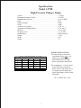
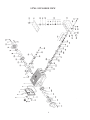
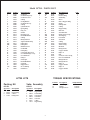
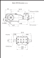
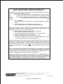
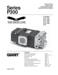
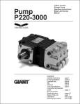
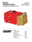
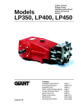
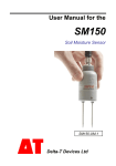
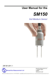
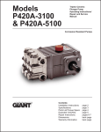
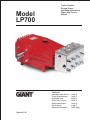
Model LP700 Triplex Ceramic Plunger Pump Operating Instructions/ Repair and Service Manual Contents: Installation Instructions: Pump Specifications: Exploded View: Parts, Kits, Torque: Repair Instructions: Dimensions: Warranty Information: Updated 12/98 page 2 page 3 page 4 page 5 page 6 page 7 back page INSTALLATION INSTRUCTIONS Installation of the Giant Industries, Inc., pump is not a complicated procedure, but there are some basic steps common to all pumps. The following information is to be considered as a general outline for installation. If you have unique requirements, please contact Giant Industries, Inc. or your local distributor for assistance. 4. Use of a dampener is necessary to minimize pulsation at drive elements, plumbing, connections, and other system areas. The use of a dampener with Giant Industries, Inc. pumps is optional, although recommended by Giant Industries, Inc. to further reduce system pulsation. Dampeners can also reduce the severity of pressure spikes that occur in systems using a shut-off gun. A dampener must be positioned downstream from the unloader. 1. The pump should be installed flat on a base to a maximum of a 15 degree angle of inclination to ensure optimum lubrication. 5. Crankshaft rotation on Giant Industries, Inc. pumps should be made in the direction designated by the arrows on the pump crankcase. Reverse rotation may be safely achieved by following a few guidelines available upon request from Giant Industries, Inc. Required horsepower for system operation can be obtained from the chart on page 3. 2. The inlet to the pump should be sized for the flow rate of the pump with no unnecessary restrictions that can cause cavitation. Teflon tape should be used to seal all joints. If pumps are to be operated at temperatures in excess of 1040 F, it is important to insure a positive head to the pump to prevent cavitation. 6. Before beginning operation of your pumping system, remember: Check that the crankcase and seal areas have been properly lubricated per recommended schedules. Do not run the pump dry for extended periods of time. Cavitation will result in severe damage. Always remember to check that all plumbing valves are open and that pumped media can flow freely to the inlet of the pump. 3. The discharge plumbing from the pump should be properly sized to the flow rate to prevent line pressure loss to the work area. It is essential to provide a safety bypass valve between the pump and the work area to protect the pump from pressure spikes in the event of a blockage or the use of a shut-off gun. Finally, remember that high pressure operation in a pump system has many advantages. But, if it is used carelessly and without regard to its potential hazard, it can cause serious injury. IMPORTANT OPERATING CONDITIONS Failure to comply with any of these conditions invalidates the warranty. 1. Prior to initial operation, add oil to the crankcase so that oil level is between the two lines on the oil dipstick. DO NOT OVERFILL. 2. Pump operation must not exceed rated pressure, volume, or RPM. A pressure relief device must be installed in the discharge of the system. Use SAE 90 Industrial gear oil. 3. Acids, alkalines, or abrasive fluids cannot be pumped unless approval in writing is obtained before operation from Giant Industries, Inc. Crankcase oil should be changed after the first 50 hours of operation, then at regular intervals of 500 hours or less depending on operating conditions. 4. Run the pump dry approximately 10 seconds to drain the water before exposure to freezing temperatures. 2 Specifications Model LP700 High-Pressure Plunger Pump Volume ..................................................................................................7.9 GPM Maximum Discharge Pressure .............................................................7250 PSI Maximum Inlet Pressure ......................................................................Up to 90 PSIG1 RPM .....................................................................................................1000 Plunger Diameter ..................................................................................18mm Stroke ....................................................................................................42mm Crankcase Oil Capacity ........................................................................102 fl. oz. Temperature of Pumped Fluids .............................................................Up to 104 oF Inlet Port ...............................................................................................2 x 3/4" NPT Discharge Ports ....................................................................................2 x 1/2" NPT Shaft Rotation .......................................................................................Either Direction2 Weight ...................................................................................................173 lbs. Width .....................................................................................................20.9" Height ...................................................................................................7.9" LP700 HORSEPOWER CHART RPM 500 600 700 800 900 1000 GPM 3000 PSI 5000 PSI 6000 PSI 7250 PSI 3.9 8.1 13.5 16.3 19.6 4.7 9.8 16.3 19.6 23.7 5.3 11.0 18.4 22.1 26.7 6.3 13.1 21.9 26.3 31.7 7.1 14.8 24.7 29.6 35.7 7.9 16.5 27.4 32.9 39.8 HORSEPOWER RATINGS: The rating shown are the power requirements for the pump. Gas engine power outputs must be approximately twice the pump power requirements shown above. We recommend a 1.15 service factor be specified when selecting an electric motor as the power source. To compute specific pump horsepower requirements, use the Following formula: HP = (GPM X PSI) / 1440 3 LP700 EXPLODED VIEW 4 Model LP700 - PARTS LIST ITEM # 1 2 4 5 6 8 9 10 11 12 13 14 15 16 17 20 20A 20B 21 22 23 24 25 28 29 30 31 32 33 33A 35 PART # 07759 13000 06085 07104 07186 06086 01009 01010 01011 07109 07182 07111 07112 07113 07114 07116 07117 13001 07118 13242 13243 13340 13341 13232 06366 07779 07133 13418 13419 08087 13420 DESCRIPTION Crankcase Oil Filler Plug Assy Crankcase Cover O-Ring Oil Sight Glass Oil Dipstick Assy O-Ring Cylinder Screw Spring Ring Plug 1/2" Gasket Bearing Cover Radial Shaft Seal O-Ring Hexagon Screw Taper Roller Bearing Fitting Disc Fitting Disc Shaft Protector Crankshaft Fitting Key Connecting Rod Assy Crosshead/Plinger Assy Crosshead Pin Plunger Oil Scraper Radial Shaft Seal Clip Ring Support Disc Grooved Ring Seal Sleeve QTY 1 1 1 1 1 1 1 4 5 1 1 2 2 2 8 2 1-3 1 1 1 1 3 3 3 3 3 3 3 3 3 3 ITEM # 35A 36 36A 37 38 38A 39 40 41 42 43 44A 44B 44C 44D 44E 44F 45 46 47 48 49 50 51 52 53 54 55 55A 56 56A LP700 KITS Packing Kit #09490 Qty Part # 3 3 6 3 08087 06359 06360 13424 Description V-Sleeve Pressure Ring V-Sleeve Leakage Seal DESCRIPTION Lock Pin Pressure Ring Guide Ring Sleeve Sleeve Support Ring Spring Leakage Seal O-Ring Support Ring Seal Case Valve Retainer Spring Tension Cap Valve Spring Valve Plate Valve Seat O-Ring Support Ring Valve Casing Stud Bolt Hexagon Nut Copper Washer Plug 1/4" Plug Cover for Valve Casing Disc for Crankshaft Hexagon Screw Hexagon Screw Plug 1/2" Copper Washer Plug 1/2" Copper Washer QTY 3 3 3 3 3 3 3 9 9 3 3 6 6 6 6 6 6 1 8 8 3 3 3 1 1 1 8 1 1 1 1 TORQUE SPECIFICATIONS Position Valve Assembly #09491 Qty Part # 9 9 6 6 6 6 6 6 PART # 22764 06359 13421 06360 13422 13423 13424 07214 06361 13425 13426 06362 07283 06363 06364 07035 13427 13428 13429 13430 07161 13261 13431 13432 13020 13021 13433 13434 06272 07703 07704 07214 06361 06362 07283 06363 06364 07035 13427 24 29 54 Description O-Ring Support Ring Tension Ring Valve Spring Valve Plate Valve Seat O-Ring Support Ring 5 Description Connecting Rod Plunger Hexagon Screws Torque Amount 264 in.-lbs. 22 ft.-lbs. 59 ft.-lbs. REPAIR INSTRUCTIONS - Model LP700 VALVE REPLACEMENT 1) Discharge Valves: Screw out 8 x hexagon screw (54), remove cover (51). Screw hexagon screw (54) into thread of plug (50) and pull out plug. Using a clipring pliers, remove spring tension cup (44A) and valve seat (44D). If necessary, use a dia 12 pull-out tool to remove valve seat. Cheack parts, and replace if worn. 2) Check O-rings (40/44E) and support rings (41/44F) and replace as necessary. 3) Tighten hexagon screws (54) TO 59 ft. lbs. 4) Suction Valves: Unscrew 8 x nut (47), remove valve casing (45) from seal sleeves (42). Using two screwdrivers, lever out seal case (42) from valve casing. Remove Spring tension cup (44A) and valve seat (44D) with a clipring pliers. If necessary, use a dia 12 pull-out tool to remove valve seat. Check parts, and replace if worn. 5) Check O-rings (40/44E) and support rings (41/44F) and replace as necessary. SEAL AND PLUNGER REPLACEMENT 1) Unscrew the 8 x nut (47), remove valve casing by pulling it out to the front. Remove seal sleeve (35). Remove tension spring (38A) and seal parts (36-38) from seal sleeve. Check plunger surface and seals (37). Replace worn parts. 2) After removing clipring (32) and support ring (33), check leakage seal (33A) and replace if necessary. 3) If the surface of the plunger is worn, screw out the plunger (29) with a size 13 tool. Clean centring and front surface of crosshead with plunger (25). 4) Thread new plunger carefully through oiled seals in seal sleeve. Coat thread of new plunger lightly with suitable bonding agent (locktite). 5) Then insert seal sleeve with plunger into crankcase guide. Crank drive until plunger with crosshead (25) pushes against plunger (29). Tighten plunger (29) to 22 ft. lbs. using a size 13 torque wrench. NOTE: The leakage seal (39) has to be installed so that its cut-outs cover the 3 mm dia. bores of the seal sleeves (35) as well as the 3 mm dia. drip-return bores of the valve casing. DISASSEMBLY OF CRANKCASE 1) Remove valve casing (#43) and plunger pipe (#28B), drain oil. 2) Screw off gear cover (#4) and bearing cover (#14). 3) Remove connecting rod screws (#24) and push the front of connecting rod forward as far as possible. Remove back halves of connecting rods, note which position from which they came from. 4) Turning the crankshaft slightly, carefully hit on side of crankshaft (#22) with a rubber mallet until crankshaft is loose. 5) Check crankshaft and bearing for damage, replace if needed. REASSEMBLY 6) Using a soft tool, press in the outer bearing ring until the outer edge lines up with the outer edge of crankcase (#1). Attach bearing cover (#14) with shaft seal and o-ring (#16) in place. Fit crankshaft through bearing hole on the opposite side. Press in bearing with bearing cover, keeping the shaft in a horizontal position and turning it slowly so that taper rollers touch the edge of outer bearing ring. 7) Adjust axial bearing clearance to at least .004" and maximum at .006 by placing fitting discs (#20A & 20B) under the bearing cover. 8) After assembly the shaft should turn easily with very little clearance. 9) Bolt connecting rod halves together making sure they are replaced in the same position from which they came from. Tighten connecting rod screws to 264 in.-lbs. 6 Model LP700 Dimensions 7 (inches) GIANT INDUSTRIES LIMITED WARRANTY Giant Industries, Inc. pumps and accessories are warranted by the manufacturer to be free from defects in workmanship and material as follows: 1. For portable pressure washers and car wash applications, the discharge manifolds will never fail, period. If they ever fail, we will replace them free of charge. Our other pump parts, used in portable pressure washers and in car wash applications, are warranted for five years from the date of shipment for all pumps used in NONSALINE, clean water applications. 2. One (1) year from the date of shipment for all other Giant industrial and consumer pumps. 3. Six (6) months from the date of shipment for all rebuilt pumps. 4. Ninety (90) days from the date of shipment for all Giant accessories. This warranty is limited to repair or replacement of pumps and accessories of which the manufacturers evaluation shows were defective at the time of shipment by the manufacturer. The following items are NOT covered or will void the warranty: 1. Defects caused by negligence or fault of the buyer or third party. 2. Normal wear and tear to standard wear parts. 3. Use of repair parts other than those manufactured or authorized by Giant. 4. Improper use of the product as a component part. 5. Changes or modifications made by the customer or third party. 6. The operation of pumps and or accessories exceeding the specifications set forth in the Operations Manuals provided by Giant Industries, Inc. Liability under this warranty is on all non-wear parts and limited to the replacement or repair of those products returned freight prepaid to Giant Industries which are deemed to be defective due to workmanship or failure of material. A Returned Goods Authorization (R.G.A.) number and completed warranty evaluation form is required prior to the return to Giant Industries of all products under warranty consideration. Call (419)-531-4600 or fax (419)-531-6836 to obtain an R.G.A. number. Repair or replacement of defective products as provided is the sole and exclusive remedy provided hereunder and the MANUFACTURER SHALL NOT BE LIABLE FOR FURTHER LOSS, DAMAGES, OR EXPENSES, INCLUDING INCIDENTAL AND CONSEQUENTIAL DAMAGES DIRECTLY OR INDIRECTLY ARISING FROM THE SALE OR USE OF THIS PRODUCT. THE LIMITED WARRANTY SET FORTH HEREIN IS IN LIEU OF ALL OTHER WARRANTIES OR REPRESENTATION, EXPRESS OR IMPLIED, INCLUDING WITHOUT LIMITATION ANY WARRANTIES OR MERCHANTABILITY OR FITNESS FOR A PARTICULAR PURPOSE AND ALL SUCH WARRANTIES ARE HEREBY DISCLAIMED AND EXCLUDED BY THE MANUFACTURER. GIANT INDUSTRIES, INC., 900 N. Westwood Ave., P.O. Box 3187, Toledo, Ohio 43607 PHONE (419) 531-4600 FAX (419) 531-6836 www.giantpumps.com Ó Copyright 1998 Giant Industries, Inc. 12/98 LP700.pm6 Ó Copyright 1998 Giant Industries, Inc.