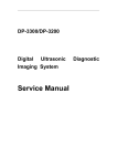
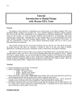
1
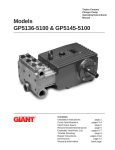
Model LP121HT Updated 3/98 Triplex Ceramic Plunger Pump Operating Instructions/ Repair and Service Manual Contents: Installation Instructions: Pump Specifications: Exploded View: Parts List / Kits: Torque Specifications: Operating Instructions: Repair Instructions: Dimensions: Warranty Information: page 2 page 3 page 4 page 5 page 5 page 6 pages 7 back page back page INSTALLATION INSTRUCTIONS 4. Use of a dampener is necessary to minimize pulsation at drive elements, plumbing, connections, and other system areas. The use of a dampener with Giant Industries, Inc. pumps is optional, although recommended by Giant Industries, Inc. to further reduce system pulsation. Dampeners can also reduce the severity of pressure spikes that occur in systems using a shut-off gun. A dampener must be positioned downstream from the unloader. Installation of the Giant Industries, Inc., pump is not a complicated procedure, but there are some basic steps common to all pumps. The following information is to be considered as a general outline for installation. If you have unique requirements, please contact Giant Industries, Inc. or your local distributor for assistance. 1. The pump should be installed flat on a base to a maximum of a 15 degree angle of inclination to ensure optimum lubrication. 5. Crankshaft rotation on Giant Industries, Inc. pumps should be made in the direction designated by the arrows on the pump crankcase. Reverse rotation may be safely achieved by following a few guidelines available upon request from Giant Industries, Inc. Required horsepower for system operation can be obtained from the chart on page 3. 2. The inlet to the pump should be sized for the flow rate of the pump with no unnecessary restrictions that can cause cavitation. Teflon tape should be used to seal all joints. If pumps are to be operated at temperatures in excess of 2210 F, it is important to insure a positive head to the pump to prevent cavitation. See Page 6 6. Before beginning operation of your pumping system, remember: Check that the crankcase and seal areas have been properly lubricated per recommended schedules. Do not run the pump dry for extended periods of time. Cavitation will result in severe damage. Always remember to check that all plumbing valves are open and that pumped media can flow freely to the inlet of the pump. 3. The discharge plumbing from the pump should be properly sized to the flow rate to prevent line pressure loss to the work area. It is essential to provide a safety bypass valve between the pump and the work area to protect the pump from pressure spikes in the event of a blockage or the use of a shut-off gun. Finally, remember that high pressure operation in a pump system has many advantages. But, if it is used carelessly and without regard to its potential hazard, it can cause serious injury. IMPORTANT OPERATING CONDITIONS Failure to comply with any of these conditions invalidates the warranty. 2. Pump operation must not exceed rated pressure, volume, or RPM. A pressure relief device must be installed in the discharge of the system. 1. Prior to initial operation, add oil to the crankcase so that oil level is between the two lines on the oil dipstick. DO NOT OVERFILL. Use SAE 90 Industrial Gear Oil. 3. Acids, alkalines, or abrasive fluids cannot be pumped unless approval in writing is obtained before operation from Giant Industries, Inc. Crankcase oil should be changed after the first 50 hours of operation, then at regular intervals of 500 hours or less depending on operating conditions. 4. Run the pump dry approximately 10 seconds to drain the water before exposure to freezing temperatures. 2 Specifications LP121HT Pump Volume ........................................................................................................ Up to 17.6 GPM Discharge Pressure ..................................................................................... Up to 1200 PSI Inlet Pressure .............................................................................................. Up to 90 PSI Speed .......................................................................................................... Up to 570 RPM Plunger Diameter ........................................................................................ 36 mm Stroke .......................................................................................................... 40 mm Crankcase Oil Capacity .............................................................................. 116 fl.oz. Temperature of Pumped Fluids .................................................................. Up to 221 oF Inlet Port ..................................................................................................... 1" BSP Discharge Port ............................................................................................ 1-1/4" BSP Crankshaft Mounting .................................................................................. Either Side Shaft Rotation ................................................................................ Top of Pulley Towards Fluid End Weight......................................................................................................... 110 lbs. Crankshaft Diameter ................................................................................... 35 mm PULLEY INFORMATION Pulley selection and pump speed are based on a 1725 RPM motor and "B" section belts. When selecting desired GPM, allow for a ±5% tolerance on pumps output due to variations in pulleys, belts and motors among manufacturers. 1. Select GPM required, then select appropriate motor and pump pulley from the same line. 2. The desired pressure is achieved by selecting the correct nozzle size that corresponds with the pump GPM. HORSEPOWER INFORMATION Horsepower ratings shown are the power requirements for the pump. Gas engine power outputs must be approximately twice the pump power requirements shown above. We recommend that a 1.1 service factor be specified when selecting an electric motor as the power source. To compute specific pump horsepower requirements, use the following formula: (GPM X PSI)/1450 = HP LP121HT PULLEY SELECTION AND HORSEPOWER REQUIREMENTS RPM 200 300 400 500 570 GPM 6.2 9.3 12.4 15.5 17.6 300 PSI 1.3 1.9 2.6 3.2 3.7 600 PSI 2.6 3.8 5.1 6.4 7.3 900 PSI 3.8 5.8 7.7 9.6 11.0 1200 PSI 5.1 7.7 10.2 12.8 14.6 3EXPLODED VIEW - LP121HT EXPLODED VIEW - LP121HT PUMP 4PARTS LIST - LP121HT PUMPItem 1 07759 Crankcase 1 Part Description Qty. PARTS LIST - LP121HT PUMP Item 1 2 4 5 6 8 9 10 11 12 13 14 15 16 17 20 20A 20B 21 22 23 24 25 Part 07759 13000 06085 07104 07186 06086 01009 01010 01011 07109 07182 07111 07112 07113 07114 07116 07117 13001 07118 07119 07120 07121 07123 28 29A 29B 29C 29D 07124 07125 07736 07131 07755 Description Qty. Crankcase 1 Oil Filler Plug Assy. 1 Crankcase Cover 1 O-Ring 1 Oil Sight Glass Assy. 1 Oil Dipstick Assy. 1 O-Ring 1 Screw 4 Spring Washer 12 Oil Drain Plug 1 Gasket 1 Bearing Cover 2 Crankshaft Seal 2 O-Ring 2 Hex Screw 8 Taper Roller Bearing 2 Shim 1-3 Shim 1-3 Shaft Protector 1 Crankshaft 1 Key 1 Connecting Rod Assy. 3 Crosshead Plunger Base Assy. 3 Crosshead Pin 3 Sleeve 3 Plunger Pipe 3 Plunger Bolt 3 Copper Gasket 3 Item 30 31 Part 13233 06120 31A 32 32A 33 35 36 37 38 39 40 41 42 43 44A 46A 46B 46C 46D 48 49 49A 49B 50 50A 52 53 06118 06116 06119 06117 07135 13291 07139 07140 07142 13199 07146 07147 13018 07150 07064 07063 07062 07066 07156 07157 07158 07159 07423 07161 13020 13021 Description Qty. Flinger 3 Seal Retainer, Complete (#31A, 32, 32A, & 33) 3 Oil Seal 3 Oil Seal Retainer 3 O-Ring 3 Backup Seal 3 Seal Sleeve 3 Leakage Seal 3 Seal Case 3 O-Ring 6 Pressure Ring 3 V-Sleeve 6 Support Ring 3 Tension Spring 3 Valve Casing 1 O-Ring 9 Valve Seat 6 Valve Plate 6 Valve Spring 6 Spring Retainer 6 Plug 3 Stud Bolt 8 Nut 8 Washer 8 Plug 1 Gasket 1 Disc for Crankshaft 1 Hexagon Screw 1 LP121HT PUMP REPAIR KITS Plunger Packing Kit #09310 Qty. Part No. Description 3 13291 Leakage Seal 6 07140 O-Ring 6 13199 V-Sleeve Valve Assembly Kit Qty. Part No. 1 07064 1 07063 1 07062 #09196 Description Valve Seat Valve Plate Valve Spring LP121HT PUMP TORQUE SPECIFICATIONS Position Item# Description 24 29C 48 49A 07121 07131 07156 07158 Connecting Rod Screws Plunger Bolt Valve Plug Nut, Stud Bolt 5 Torque Amount 310 in.-lbs. 33 ft.-lbs. 107 ft.-lbs. 59 ft.-lbs. Supplementary Plant Lay-Out Instructions - LP121HT PUMP Pressure in Inlet Side The stipulated NPSHR is the minimum required pressure above the vapor pressure of the medium and is never to fall short of this figure. Temperature and vapor pressure of the medium, the geodetical height of the location, the flow rate and the loss of friction in the suction line, must all be taken into consideration. It may be necessary to install a booster pump (centrifugal) in the suction line. Pulsation Due to its construction, the plunger pump creates pulsation in the inlet and discharge lines. In particular, inlet pulsation must be dampened in order to prevent resonance in the suction line which in turn causes cavitation. Therefore, the pump is never to be connected by a rigid pipe. Rather, use a flexible hose, which is not reinforced by steel, that is 1.5 to 2 times wider than the inlet port. If a booster pump is used, the hose is to be attached between the booster pump and the high pressure pump. If several pumps are used, each pump must have its own inlet line. If this cannot be done, an inlet air chamber or inlet flow stabilizer must be installed in front of each pump. The bladder in the stabilizer is to be pre-tensioned on location. Depending on the layout of the plant, a pressure accumulator may be necessary on the discharge side. The pressure accumulator must be installed right behind the discharge outlet of the high pressure pump. Only use one pressure accumulator (in the discharge line) at a time in order to avoid irritation which could be caused by different pretension levels in the accumulators. Gas-tension in both the inlet flow stabilizer and the pressure accumulator are to be checked regularly. 6 REPAIR INSTRUCTION - LP121HT PUMP To Check Valves Loosen valve plugs (48). Either with needle nose pliers or with a M12 screw, which can be threaded into the hole of the spring retainer (46D), take out discharge and inlet valve assemblies. Press onto the valve plate (46B) and twist to take apart the valve assembly. Check and replace worn parts. Tighten the plug to 107 ft.-lbs. To Check Seals and Plungers Loosen the eight nuts (49A) and take off the valve casing (43). Remove the seals (40) on the valve casing. Take seal sleeve (35) out of the guides in the crankcase (1) and remove the leakage seals (36). Check plunger pipes (29B) for damage and remove any dirt. When replacing plunger pipes, use new copper rings (29D). Apply loctite on threads of plunger bolts (29C) and tighten to 33 ft.-lbs. Check seals and replace as necessary. Place new v-sleeves (40) along with support rings (41) in the valve casing (43). Place seals (36) and pressure rings (39) in seal sleeve (35). Install the complete unit in the valve casing. Finally, fit in the complete pump head assembly carefully over the plunger pipes and evenly tighten nuts to 59 ft.-lbs. To Dismantle Gear End After removing the valve casing (1) and plunger pipes (29B), drain the oil. Take off crankcase cover (4) and bearing cover (14). Loosen connecting rod screws (24) and push the connecting rod/plunger base assembly forward (as far as possible) into the crosshead guides. Caution: Connecting rods are marked for identification. Do not twist connecting rod halves. Connecting rods are to be reinstalled in the same position on the crankshaft journals. Turning the crankshaft (22) slightly, hit it out carefully to the side with a rubber hammer. Caution: Do not bend the connecting rod shanks. Check crankshaft and connecting rod surfaces, shaft seals (15) and taper roller bearings (20). To Reassemble Using a soft tool, press in the outer bearing ring until the outer edge is aligned with the outer edge of the bearing hole. Take off bearing cover (14) together with shaft seal (15) and o-ring (16). Fit crankshaft (22) through bearing hole on the opposite side. Press in outer bearing and tension it inwards with the bearing cover (keeping the shaft in a vertical position and turning slowly so that the taper rollers of the bearings touch the edge of the outer bearing ring). Adjust axial bearing clearance to at least 0.1mm and a maximum of 0.15mm by placing fitting discs (20A and 20B) under the bearing cover. Caution: After assembly, the crankshaft (22) should turn easily with very little clearance. Tighten connecting rod screws (24) to 310 in.-lbs. NOTE: Contact Giant Industries for Service School Information. Phone: (419)-531-4600 GIANT INDUSTRIES LIMITED WARRANTY Giant Industries, Inc. pumps and accessories are warranted by the manufacturer to be free from defects in workmanship and material as follows: 1. For portable pressure washers and car wash applications, the discharge manifolds will never fail, period. If they ever fail, we will replace them free of charge. Our other pump parts, used in portable pressure washers and in car wash applications, are warranted for five years from the date of shipment for all pumps used in NON-SALINE, clean water applications. 2. One (1) year from the date of shipment for all other Giant industrial and consumer pumps. 3. Six (6) months from the date of shipment for all rebuilt pumps. 4. Ninety (90) days from the date of shipment for all Giant accessories. This warranty is limited to repair or replacement of pumps and accessories of which the manufacturers evaluation shows were defective at the time of shipment by the manufacturer. The following items are NOT covered or will void the warranty: 1. Defects caused by negligence or fault of the buyer or third party. 2. Normal wear and tear to standard wear parts. 3. Use of repair parts other than those manufactured or authorized by Giant. 4. Improper use of the product as a component part. 5. Changes or modifications made by the customer or third party. 6. The operation of pumps and or accessories exceeding the specifications set forth in the Operations Manuals provided by Giant Industries, Inc. Liability under this warranty is on all non-wear parts and limited to the replacement or repair of those products returned freight prepaid to Giant Industries which are deemed to be defective due to workmanship or failure of material. A Returned Goods Authorization (R.G.A.) number and completed warranty evaluation form is required prior to the return to Giant Industries of all products under warranty consideration. Call (419)-531-4600 or fax (419)-531-6836 to obtain an R.G.A. number. Repair or replacement of defective products as provided is the sole and exclusive remedy provided hereunder and the MANUFACTURER SHALL NOT BE LIABLE FOR FURTHER LOSS, DAMAGES, OR EXPENSES, INCLUDING INCIDENTAL AND CONSEQUENTIAL DAMAGES DIRECTLY OR INDIRECTLY ARISING FROM THE SALE OR USE OF THIS PRODUCT. THE LIMITED WARRANTY SET FORTH HEREIN IS IN LIEU OF ALL OTHER WARRANTIES OR REPRESENTATION, EXPRESS OR IMPLIED, INCLUDING WITHOUT LIMITATION ANY WARRANTIES OR MERCHANTABILITY OR FITNESS FOR A PARTICULAR PURPOSE AND ALL SUCH WARRANTIES ARE HEREBY DISCLAIMED AND EXCLUDED BY THE MANUFACTURER. GIANT INDUSTRIES, INC., 900 N. Westwood Avenue, P.O. Box 3187, Toledo, OH 43607 PHONE: (419) 531-4600, FAX: (419) 531-6836, www.giantpumps.com Ó Copyright 1998 Giant Industries, Inc.