1
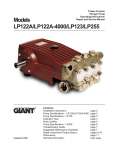
Model LP1000 Updated 9/00 Triplex Ceramic Plunger Pump Operating Instructions/ Repair and Service Manual Contents: Installation/Repair Instructions: Exploded View: Parts List / Kits: Torque Specifications: Pump Specifications: Pump Dimensions: Warranty Information: pages 2-7 page 8 page 9 page 9 page 10 page 11 back page INSTALLATION INSTRUCTIONS Installation of the Giant Industries, Inc., pump is not a complicated procedure, but there are some basic steps common to all pumps. The following information is to be considered as a general outline for installation. If you have unique requirements, please contact Giant Industries, Inc. or your local distributor for assistance. 1. Set-Up and Installation The pump is to be mounted horizontally onto a solid frame that is also to accommodate the drive motor. The place of installation has to be chosen so that the belt drive and pump are made easily accessible for maintenance work (oil dip stick and oil filler plug must also be easy to reach.) 1.1 Pump Important! The preferred drive form is with toothed belts. Bare V-belts are admissible if the exact required belt tension can be kept. Excessive belt tension can lead to increased heating of the drive system, and can even lead to breakage of the crankshaft. Important! The direction of rotation of the pump is indicated by an arrow on both bearing flanges situated of the crankcase. The indicated direction of rotation must be observed to ensure that gear parts are properly lubricated. 1.1.1 Hydraulic Connections a.) Inlet Line · · · On both sides of the pump head there is one ½ suction port and one 3/8 discharge port. Non-required portholes can be closed with the supplied plugs and bonding agent. Suction and discharge connections are to be fitted with elastic tubes to damp vibrations and guard the pump against pipeline tensions. The diameter of the suction line must be at least one size bigger than the suction inlet port. Important! The pump is not to be connected directly to the water mains as gas bubbles present in fresh water can lead to premature wear and destruction of seals and valves. A feed tank with a volume at least 5 times greater than the pump discharge rate per minute is to be installed. The feed tank must be fitted with baffle plates to stop any air coming into the tank from passing on through the suction port. · The necessary input pressure of 36.0 PSI (2.5 Bar) bar must be guaranteed using a centrifugal pump. A filter (max. particle size 50 micron) with a volume at least 3 times greater than the pump discharge rate per minute must be fitted between the centrifugal pump and high pressure pump. To check the required input pressure, we recommend the installation of a pressure gauge between the filter and high pressure pump. Important! All fittings must be tightly fixed to avoid air entering into suction line. To avoid dirt entering into the pump head, the suction line should be thoroughly rinsed before being fixed to the suction port. b.) Discharge Line · Tubes, pipes and fittings of the discharge line must have a safety factor well above the maximum operating pressure. · A suitable safety valve must be installed immediately after the initial length of flexible discharge line. There are to be no shut-off valves between the pump and safety valve. · An air vent should be built into the discharge line as near as possible to the pump. · The most optimal place for installing a pressure gauge is between the pump and safety valve. The second outlet on the pump casing can also be used for this purpose. · The discharge line is to be laid either horizontally or rising steadily away from the pump. · Return-flow lines from unloader valves and safety valves must be connected to the feed tank, never directly to the suction port. Finally, remember that high pressure operation in a pump system has many advantages. But, if it is used carelessly and without regard to its potential hazard, it can cause serious injury. NOTE: Contact Giant Industries for Service School Information. Phone: (419)-531-4600 2 Hydraulic System Set Up Intake Feed Tank Bypass Return 1 2 3 4 2.2 Coarse Filter Booster pump Fine-particle filter Gauge to check input pressure 5 LP1000 High pressure pump 6 High pressure gauge 7 Excess, Safety valve Pressure Accumulator The purpose of the pressure accumulator, if installed, is to damp pulsation from the high-pressure pump and thus avoid vibrations in the discharge line. Gas in the pressure accumulator should be pretensioned to 50-60% of the maximum operating pressure. The correctly pretensioned gas must be checked regularly (approx. every 2 months see separate operating instructions for pressure accumulator if necessary.) 3. Operation Operation and Maintenance · Check pump oil level and if necessary fill up (refer to specification information on page 8). First oil change to be made after 50 hours of operation; thereafter oil must be changed every 500 operating hours or at least every 6 months, whichever comes first. Caution when operating in damp places or with high temperature fluctuations. Oil must be changed immediately, should condensate ( frothy oil) occur in the gear end. · · · · · Before the high pressure pump is started, the centrifugal pump must produce the min. intake pressure of 36.0 PSI (2.5 Bar.) Open discharge line (e.g. spray gun) to enable booster pump to vent the system. Open all regulator valves and other shut-off agents. Activate bypass system or switch pressure regulating valve to bypass to enable pressure-free start. Start motor briefly to check the direction of rotation. Pay careful attention to the direction of rotation that is specified for the pump (arrows indicated on crankcase.) To serve this purpose, the pump must only be dry run for a short period (approx. 30 sec.). Start the pump and let it run in pressure-free bypass operation for approx. 2 minutes to enable the automatic functioning seal cooling system to vent itself. · Important! A small portion of water from the suction chamber which runs through the seal sleeves and steel elbow pipes is led off to pass behind the high-pressure seals to cool these. As a result of heat dissipation, the elbow pipes are approx. 41-50° F (5-10°C) warmer than the water temperature on the suction side. Important! Check regularly to ensure elbow pipes do not overheat. If pipes become very hot (indication of seal wear,) stop pump immediately and examine seals and plungers (see maintenance section.) · Listen carefully for an even running sound. If the pump begins to run irregularly or pulsate strongly, it can be that one of the three plungers is not vented. In this case, the pump should be started and stopped at quick intervals to ease venting. Venting is also made easier if the vent tap in the discharge line is opened. 3 4. Maintenance and Repair To Check Valves: Discharge Valves: Screw out hexagon screws (59) and remove valve casing (54). Pull seal case (46) out of valve casing (54.) Pull valve body (50) and seal case (46) apart. Using pliers, pull spring guide (55) out of the valve casing. Remove discharge valve plate (57) together with spring (56) from spring guide. (55.) Check sealing surfaces of the valve body (50) and discharge valve plate (57.) Check discharge valve spring (56) and border seal ring (53) and replace where necessary. Important! A damaged border seal ring (53) must be replaced before reassembling. Inlet Valves Remove inlet valve spring (48) with valve plate (49) from seal case (46.) Check sealing surfaces of the valve plate (49) and valve body (50). Check O-rings (47), (51) and support ring (52) before reassemble. Worn parts must be replaced. 4 To Check Seals and Plungers Unscrew hexagon screw (59) and take off valve casing (54.) Remove the screw-in joints (37B) and take off the elbow pipes (37A). Remove drip-return ring (44) from seal sleeve (36). Then pull seal sleeve (36) out of the crankcase. Take the seal tension spring (41) out of seal sleeve (36). Using pliers, remove the clip ring (32) situated on the other side of the sleeve; then take out support ring (33) and grooved ring (35) using an extractor tool (Æ12, Æ14, or Æ16 as per plunger Æ). Using a seal extractor tool (Æ12.4, Æ14.4 or Æ16.4 as per plunger Æ), carefully press the seal unit comprising of guide ring (38,) spiral ring (39,) and supporting ring (40) out of the seal sleeve (36) from the side (36) closest to the drive. Check spiral ring (39), guide ring (38) and grooved ring (35) and replace where necessary. Check surface of plunger (29) for damage. A worn plunger (29) must be screwed out (key size 22) and replaced. Due to reasons of precision, the ceramic plunger alone cannot be exchanged. Coat the threads of the plunger lightly with an appropriate bonding agent and tighten plunger to 33 Ft-lbs. (45Nm). 5 Important! Check the leakage bores Æ4 of the seal sleeves (36) and seal cases (46) for dirt and clean if necessary. The elbow screw-in joints (37B) and elbow pipes (37A) must also be checked for dirt and cleaned if necessary. Important! The Æ4 leakage bore of the middle seal sleeve must be closed by a rubber plug (36A) to ensure water circulation from seal sleeve 1 to seal sleeve 3. Fit the drip- return unit (32/33/35,) the high-pressure seal unit (38,39,40,) and tension spring (41) into the seal sleeve. Then push the assembled seal sleeves (36) carefully onto the plungers and into the drive; thereafter mount elbow pipes (37A) as per the exploded view and tighten the screw-in joints (37B) carefully. Check O-rings on the drip-return ring (45) as well as border seal ring (43) and replace where necessary. Push the valve casing (54) with its seal cases (46) and drip-return rings (44) onto the seal sleeves (36). Tighten valve casing nuts (59) evenly to 59 ft.-lbs. (80 N-M). To Dismantle Gear First, disassemble valve casing and seal sleeves; then screw out oil plug (12) and drain oil. Thereafter screw off gear cover (4) and bearing cover (14.) 6 Remove connecting rod (conrod) screws, and push the front of the conrod parts forward as far as possible into the crosshead guide. Important! Conrods are marked for identification. Do not twist conrod halves. When reassembling, conrods are to be fitted back onto the shaft journals in their exact original position. Turning the crankshaft gently, tap it out carefully to one side using a rubber hammer. Important! Do not bend conrod shafts. Check the running surface of the shaft and conrods as well as the shaft seal rings and tapered roller bearings. To Reassemble Gear End Using a soft tool, press in outer bearing ring on one side of the crankcase until its outer edge sits evenly on the bearing bore. Then screw on bearing cover together with shaft seal ring and O- ring. Insert shaft through the bearing hole on the opposite side. Press in outer bearing ring and tension inwards with bearing cover, keeping the shaft in vertical position and turning it slowly so that the tapered rollers of the bearing sit evenly on the outer bearing ring. Adjust axial bearing clearance to at least 0.1mm and maximum 0.15mm by placing fitting discs (20A) under one of the bearing covers. Important! After assembly has been completed, the shaft should turn easily with very little clearance. Tighten conrod screws to 26 Ft.-lbs. (35 Nm). 7 Model LP1000 - Exploded View 8 Model LP1000 - PARTS LIST ITEM# 1 2 4 5 6 8 9 10 11 12 13 14 15 16 17 20 20A 20B 21 22 23 24 25 28 29 30 31 32 33 35 PART # 07759 13000 06085 07104 07186 06086 01009 01010 01011 07109 07182 07111 07112 07113 07114 07116 07117 13001 07118 13242 13243 13340 13341 13232 06583 07779 07133 06584 06610 07391 DESCRIPTION Crankcase Oil Filler Plug Assy Crankcase Cover O-Ring for Cover Oil Sight Glass Oil Dipstick Assy O-Ring for Oil Dipstick Cylinder Screw Spring Ring Plug G 1/2" Gasket Bearing Cover Radial Shaft Seal O-Ring for Bearing Cover Hexagon Screw Taper Roller Bearing Fitting Disc Fitting Disc Shaft Protector Crankshaft Fitting Key Connecting Rod Assy Crosshead/Plunger Assy Crosshead Pin Plunger Assembly Oil Scraper Radial Shaft Seal Clip Ring Support Disc Grooved Ring QTY 1 1 1 1 1 1 1 4 5 1 1 2 2 2 8 2 1-3 1-3 1 1 1 3 3 3 3 3 3 3 3 3 ITEM# 36 36A 37A 37B 37C 37D 38 39 40 41 42 43 44 45 46 47 48 49 50 51 52 53 54 55 56 57 58 59 60 61 PART # 06585 06586 06587 06588 06589 07258-0100 06590 06591 06592 06593 06594 06595 06596 06560 06597 07740 07750 06598 06599 12092 06600 06601 06602 06603 12090 06604 06605 06606 13020 06602 DESCRIPTION Seal Sleeve Plug Elbow for Rinsing Pipe Screw-in Pipe Connection Plug G 1/8 c/w Hexagon Steel Washer Sleeve Support Ring Spiral Ring Support Ring Seal Tension Spring Spring Tension Ring Border Seal Ring Drip-Return Ring O-Ring Seal Case O-Ring Valve Spring Inlet Valve Plate Valve Body O-Ring Support Ring for item #51 Border Seal Ring Valve Casing Spring Guide Valve Spring Discharge Valve Plate Stud Bolt Hexagon Screw Disc for Crankshaft Hexagon Screw LP1000 KITS Seal Repair Kit #09517 Qty Part # 3 3 3 3 6 3 07391 06590 06591 06595 06560 07740 Description Grooved Ring Sleeve Support Ring Spiral Ring Border Seal Ring O-Ring O-Ring Valve Repair Kit #09518 Qty Part # 3 3 3 3 3 3 3 3 3 07750 06598 06599 12092 06600 06601 06603 12090 06604 Description Valve Spring Inlet Valve Plate Valve Body O-Ring Support Ring for O-Ring Border Seal Ring Sping Guide Valve Spring Discharge Valve Plate LP1000 TORQUE SPECIFICATIONS Position 24 25 59 Item# 13340 13341 06606 Description Connecting Rod Assy. Crosshead/Plunger Assy. Hexagon Screw 9 Torque Amount 26 ft.-lbs. 33 ft.-lbs. 59 ft.-lbs. QTY 3 1 2 4 2 6 3 3 3 3 3 3 3 6 3 3 3 3 3 3 3 3 1 3 3 3 8 8 1 1 Specifications Model LP1000 High-Pressure Plunger Pump Volume ..................................................................................................3.4 GPM (12.8 LPM) Maximum Discharge Pressure .............................................................14,500 PSI (1000 Bar) Maximum Inlet Pressure ......................................................................Up to 90 PSIG (1305 Bar) RPM .....................................................................................................1000 Plunger Diameter ..................................................................................22mm Stroke ....................................................................................................42mm Crankcase Oil Capacity ........................................................................118 fl. oz. (3.5 Liters) Temperature of Pumped Fluids .............................................................Up to 104 oF (40o C) Inlet Port ...............................................................................................2 x 1/2" BSP Discharge Ports ....................................................................................2 x 3/8" BSP Shaft Rotation .......................................................................................Towards fluid end only Weight ...................................................................................................143 lbs. (65 KG) LP1000 HORSEPOWER CHART RPM GPM 7250 PSI 10,000 PSI 12,500 PSI 14,500 PSI 600 2.0 10.4 14.3 17.9 20.7 700 2.4 12.4 8.3 21.4 24.9 800 2.7 14.0 9.3 24.1 28.0 900 3.1 3.0 15.5 10.3 26.8 31.1 1000 3.4 17.6 11.7 30.4 35.2 HORSEPOWER RATINGS: The rating shown are the power requirements for the pump. Gas engine power outputs must be approximately twice the pump power requirements shown above. We recommend a 1.15 service factor be specified when selecting an electric motor as the power source. To compute specific pump horsepower requirements, use the Following formula: HP = (GPM X PSI) / 1400 10 LP1000 DIMENSIONS (mm) 11 GIANT INDUSTRIES LIMITED WARRANTY Giant Industries, Inc. pumps and accessories are warranted by the manufacturer to be free from defects in workmanship and material as follows: 1. For portable pressure washers and self-service car wash applications, the discharge manifolds will never fail, period. If they ever fail, we will replace them free of charge. Our other pump parts, used in portable pressure washers anD in car wash applications, are warranted for five years from the dateof shipment for all pumps used in NON-SALINE, cleaN water applications. 2. One (1) year from the date of shipment for all other Giant industrial and consumer pumps. 3. Six (6) months from the date of shipment for all rebuilt pumps. 4. Ninety (90) days from the date of shipment for all Giant accessories. This warranty is limited to repair or replacement of pumps and accessories of which the manufacturers evaluation shows were defective at the time of shipment by the manufacturer. The following items are NOT covered or will void the warranty: 1. 2. 3. 4. 5. 6. Defects caused by negligence or fault of the buyer or third party. Normal wear and tear to standard wear parts. Use of repair parts other than those manufactured or authorized by Giant. Improper use of the product as a component part. Changes or modifications made by the customer or third party. The operation of pumps and or accessories exceeding the specifications set forth in the Operations Manuals provided by Giant Industries, Inc. Liability under this warranty is on all non-wear parts and limited to the replacement or repair of those products returned freight prepaid to Giant Industries which are deemed to be defective due to workmanship or failure of material. A Returned Goods Authorization (R.G.A.) number and completed warranty evaluation form is required prior to the return to Giant Industries of all products under warranty consideration. Call (419)-5314600 or fax (419)-531-6836 to obtain an R.G.A. number. Repair or replacement of defective products as provided is the sole and exclusive remedy provided hereunder and the MANUFACTURER SHALL NOT BE LIABLE FOR FURTHER LOSS, DAMAGES, OR EXPENSES, INCLUDING INCIDENTAL AND CONSEQUENTIAL DAMAGES DIRECTLY OR INDIRECTLY ARISING FROM THE SALE OR USE OF THIS PRODUCT. THE LIMITED WARRANTY SET FORTH HEREIN IS IN LIEU OF ALL OTHER WARRANTIES OR REPRESENTATION, EXPRESS OR IMPLIED, INCLUDING WITHOUT LIMITATION ANY WARRANTIES OR MERCHANTABILITY OR FITNESS FOR A PARTICULAR PURPOSE AND ALL SUCH WARRANTIES ARE HEREBY DISCLAIMED AND EXCLUDED BY THE MANUFACTURER. GIANT INDUSTRIES, INC., 900 N. Westwood Avenue, P.O. Box 3187, Toledo, OH 43607 PHONE: (419) 531-4600, FAX: (419) 531-6836, www.giantpumps.com Ó Copyright 2000 Giant Industries, Inc. 9/2000 LP1000 .PM6