1
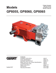
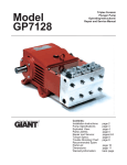
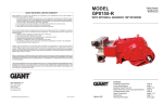
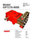
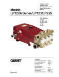
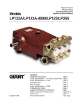
Models Triplex Ceramic Plunger Pump Operation Manual GP7145GB and GP7255AGB pump with gearbox Updated 10/07 Contents: Installation and Safety Instructions Pump Specifications (GP7145GB-2.4): Exploded View: Parts List: Pump Specifications (GP7255AGB-2.4): Kits/Torque Specifications: Maintenance Information: Repair Instructions: Troubleshooting Guide: Dimensions: Warranty Information page 2 page 3 page 4 page 5 page 6 page 7 page 7 pages 8-9 page 10 page 11 back page INSTALLATION INSTRUCTIONS Operation and Maintenance Check oil level prior to starting and ensure trouble-free water supply. Oil: Use only 2 gallons (7.5 liters) if ISO VG-220 synthetic gear oil. Initial change after 50 hours and then after every 200 operating hours. If used less than this, change once per year. IMPORTANT! When operating in humid areas (or areas with large temperature fluctuations, the oil must be changed immediately (if condensate or frothy oil occurs in the gear box). IMPORTANT! We recommend that both inlet ports be used in order to ensure cavitation-free operation and optimal suction conditions. If only one connection is use, a safety margin of 3 feet (1 meter) has to be added to the required NPSH. IMPORTANT! The GP7145GB and GP7255GB pumps have a black arrow on the reduction gear, which shows the preferred direction of rotation. The pump can be delivered either with the gear on the left side or right side (when facing the front of the pump), which eases planning assembled units with regard to the desired direction or rotation. In either case, the larger gear wheel must rotate towards the front-end of the pump. The preferred/optimal direction of rotation ensures that the oil is correctly splashed on the crosshead guides via the motion of the connecting rods, which is a particular advantage where continuous operation is involved. The pump can also be run against the recommended direction of the rotation if operated periodically or at reduced pressure. If this is the case, the pump has to be run in this direction to smoothen the bearing areas. This is done by a one-time operation at zero pressure for at least 30 minutes; thereafter, the pressure must be slowly increased over the next hour to the desired maximum operating pressure. This should run-in the pump, but you should also check the oil temperature, which should not exceed 160 o F (71 oC). The torque tension on the valve casing nuts (49A) is to be checked after approximately 200 hours. Please see page 7 for torque values. IMPORTANT! The service life of the seals is maximized if a minimal amount of leakage is present. A few drops of water can drip from each plunger every minute. Leakage has to be examine every day. If the leakage becomes excessive (constant dripping), the plunger seals must be changed. Safety Rules The operating instructions must be read and adhered to before performing any work on the pump or complete assembled unit. No responsibility will be carried by us for damage to materials or persons caused by improper handling of our pumps. Access to the pump is not allowed by unauthorized personnel. As safety valve is to be installed in accordance with the guidelines for liquid spraying units, so that the admissible operating pressure cannot be exceeded by more than 10%. Pumps operating without a safety valve as well as any excess in temperature or speed limits automatically voids the warranty. When the pump is in operating, the exposed shaft side, the driven shaft side and its coupling must be covered by a protective guard. The plunger area must also be covered by the protective plate (30). Do not step onto the protective plate (30 ) or put weight on it. Before carrying out any maintenance work to the pump or pump unit, the pressure in the discharge line and pump must be at zero. Close off the suction line. Disconnect fuses to ensure that the driving motor cannot accidently get switched on. Before starting the pump, make sure that the pump, the cooling system and all parts on the pressure side of the unit are vented and refilled with pressure at zero. In order to prevent air or air/water-mixture being absorbed and cavitation occurring, the pump NPSHR (Net Positive Suction Head Required) and water temperature must be adhered to. Cavitation and/or compression of gases lead to uncontrollable pressure kicks, which can ruin the pump and unit parts and also be dangerous to the operator or anyone standing nearby. Giant plunger pumps are suitable for pumping clean water and other non-aggressive or non abrasive media, which have a specific weight similar to water. Before pumping other liquids (in particular, flammable, explosive and toxic media), the pump manufacturer must be consulted with regard to the resistance of the pump NOTE: Contact Giant Industries for Service School Information. Phone: (419)-531-4600. 2 Specifications Model GP7145GB -2.4 U.S. ............................... (Metric) Volume (Continuous) .............................................................. 47.5 GPM ..................... (180 LPM) Volume (Intermittent) ............................................................. 60 GPM* ...................... (227 LPM)* Discharge Pressure ................................................................. 3000 PSI ....................... (207 bar)* Speed (Continuous) ........................................................................................................ 750 RPM Speed (Intermittent) ........................................................................................................ 947 RPM Inlet Pressure (maximum) ...................................................... 145 PSI ......................... (10 bar) Plunger Diameter .................................................................... 1.77” ............................. 45mm Plunger Stroke ........................................................................ 2.0” ............................... 52mm Crankshaft Diameter ............................................................... 1.9” ............................... 48mm Key Width ............................................................................... 0.6” ............................... 14mm Crankshaft Mounting ...................................................................................................... Either side Shaft Rotation ................................................................................................................. See Instructions on page 2 Temperature of Pumped Fluids .............................................. Up to 140 oF.................. (60 oC) Inlet Ports ........................................................................................................................ (2) 2-1/2" NPT Discharge Ports ............................................................................................................... (2) 1-1/4" NPT Weight ..................................................................................... 455 lbs. ......................... (206 kg) Crankcase Oil Capacity .......................................................... 1.6 Gal. ......................... (6.0 liter) Fluid End Material .......................................................................................................... Spheroidical Cast Iron Consult the factory for special requirements that must be met if the pump is to operate beyond one or more of the limits specified above. PULLEY INFORMATION Pulley selection and pump speed are based on a 1725 RPM motor and "B" section belts. When selecting desired GPM, allow for a ±5% tolerance on pumps output due to variations in pulleys, belts and motors among manufacturers. 1. Select GPM required, then select appropriate motor and pump pulley from the same line. 2. The desired pressure is achieved by selecting the correct nozzle size that corresponds with the pump GPM. HORSEPOWER INFORMATION Horsepower ratings shown are the power requirements for the pump. Gas engine power outputs must be approximately twice the pump power requirements shown above. We recommend that a 1.1 service factor be specified when selecting an electric motor as the power source. To compute specific pump horsepower requirements, use the following formula: (GPH X PSI) / 1450 = HP GP7145GB-2.4 PULLEY SELECTION & HORSEPOWER REQUIREMENTS Input RPM 720 960 1200 1440 1800 1894 2273 RPM 300 400 500 600 750 789 947 GPM 800 PSI 1000 PSI 1500 PSI 2000 PSI 3000 PSI* 19.0 10.9 13.6 20.4 27.1 40.7 25.3 14.5 18.1 27.1 36.2 54.3 31.7 18.1 22.6 33.9 45.2 67.9 38.0 21.7 27.1 40.7 54.3 81.4 47.5 27.1 33.9 50.9 67.9 101.8 50.0 28.6 35.7 53.6 71.4 107.1 60.0 34.3 42.9 64.3 85.7 128.6 * Intermittent Duty Only! 3 Exploded View - GP7145GB-2.4/GP7255AGB-2.4 4 PARTS LIST - GP7145GB-2.4/GP7255AGB-2.4 ITEM 1 1A 1B 2 4 5 8 9 10 11 12 13 14 14A 15 15A 15B 16 17 20 20A 21 22 23 24 25 28 30 30A 30B 30C 30D 31 32 33 33A 33B 33C 34 36 PART 05324 05313 01009 13000 07601 07602 07603 01009 22706 06725 07109 07182 07607 05325 07608 05326 05327 07184 05328 07610 07611 07612 13405 07614 13182 13183 13184 07619 07225-0100 13136 08280 13154 07623 07624 07626 07627 07628 07249 13137 06165 36 07706 36A 36B 36B 36C 36C 36D 38 38 38A 38B 38B 39 39 39A 07667 05157 07666 06166 07664 07665 06167 13155 13156 06258 07721 06171 13157 13290 DESCRIPTION Crankcase Head for Oil Dipstick O-Ring Oil Filler Plug Assy. Crankcase Cover Gasket, Crankcase Cover Oil Dip Stick O-Ring, Dip Stick Hexagon Screw Spring Washer Drain Plug Gasket, Drain Plug Bearing Cover Flange for Gearbox Radial Shaft Seal O-Ring Hexagon Socket Screw O-Ring Gear Seal Taper Roller Bearing Fitting Disc (Shim) Shaft Protector Crankshaft Key Connecting Rod Assy. Crosshead Assy. Crosshead Pin Cover Plate Hexagon Screw Grommet Disc Cover Plate Eye Bolt Radial Shaft Seal Seal Retainer O-Ring Circlip Fitting Disc Oil Scraper Plunger Pipe Assy. (36A-D), GP7145 Plunger Pipe Assy. (36A-D), GP7255A Plunger Connection Plunger Pipe, GP7145 Plunger Pipe, GP7255A Tension Screw, GP7145 Tension Screw, GP7255A Copper Ring Seal Case, GP7145 Seal Case, GP7255A O-Ring for 38 O-Ring for 38, GP7145 O-Ring for 38, GP7255A Seal Sleeve, GP7145 Seal Sleeve, GP7255A Grooved Ring, GP7145 QTY. 1 1 1 1 1 1 1 1 8 8 3 2 1 1 1 1 6 2 1 2 1-5 1 1 1 3 3 3 1 8 4 8 1 1 3 3 3 3 3 3 3 3 3 3 3 3 3 3 3 3 3 3 3 3 3 3 ITEM 39A 40 41 41 42 42 43 43 45 49 49A 50 50A 51 51A 51B 51C 51D 51E 51F 53 56 56A 56B 56C 56D 57 58 59A 60 61 G1 G2 G3 G4 G5 G6 G7 G8 G9 G10 G11 G12 G13 G15 G16 G17 G18 G19 G20 G21 PART 07723 07797 13296 13158 13294 07711 13293 07712 13297 13159 13160 07791 13162 05274 13165 07732-0100 05314 05136 07653 13166 22610 13167 07658 07635 13166 07653 13173 13170 07661 12251 05170 05344 05328 05329 05330 05331 05332 07008 05333 05334 05335 05336 13358 05337 05319 05338 05339 05340 13243 05341 05342 05343 DESCRIPTION QTY. Grooved Ring, GP7255A 3 Support Disc, GP7255 only 3 Support Ring, GP7145 3 Support Ring, GP7255A 3 V-Sleeve, GP7145 9 V-Sleeve, GP7255A 6 Pressure Ring, GP7145 3 Pressure Ring, GP7255A 3 Tension Spring, GP7145 only 3 Stud Bolt 8 Hexagon Nut 8 Valve Casing 1 Cylinder Stud 2 Valve Assembly (51A-51F) 6 Spacer Pipe 6 Valve Spring 6 Valve Plate 6 Valve Seat 6 O-Ring 6 Support Ring 6 Plug 3 Valve Adaptor 3 O-Ring for 56, 58 6 Support Ring for 56A, 58A 6 Support Ring 3 O-Ring 3 Tension Spring 6 Plug, M64 x 2 3 Copper Ring for 12 1 Plug, 1-1/4” NPT 1 Plug, 2-1/2” NPT 1 Gearbox Assy, 2.4:1 (G1-G21) 1 Casing, Bottom 1 Casing, Top 1 Cylindrical Pin 2 Hexagon Screw 8 Washer 6 Hexagon Socket Screw 6 Spacer Ring 2 Fitting Key 1 Cogwheel 1 Tension Disc 1 Hexagon Screw 1 Pinion 1 Ball Bearing 2 Fitting Disc 2 Fitting Disc 2 Shaft Seal Ring 1 Fitting Key 1 Washer 2 Screw Plug 2 Copper Ring 2 07662 05210 Valve Tool (Not Shown) Plunger Conversion Assy. (36-45), GP7145 Plunger Conversion Assy., (36-45), GP7255A 05211 5 1 1 1 Specifications Model GP7255AGB-2.4 U.S. ............................... (Metric) Volume (Continuous) .............................................................. 65.8 GPM ..................... (250 LPM) Volume (Intermittent) ............................................................. 80 GPM* ...................... (303 LPM)* Discharge Pressure (Continuous) ........................................... 1500 PSI ....................... (100 bar) Discharge Pressure (Intermittent) ........................................... 2000 PSI ....................... (140 bar)* Speed (Continuous) ........................................................................................................ 700 RPM Speed (Intermittent) ........................................................................................................ 851 RPM Inlet Pressure (maximum) ...................................................... 145 PSI ......................... (10 bar) Plunger Diameter .................................................................... 2.17” ............................. 55mm Plunger Stroke ........................................................................ 2.0” ............................... 52mm Crankshaft Diameter ............................................................... 1.9” ............................... 48mm Key Width ............................................................................... 0.6” ............................... 14mm Crankshaft Mounting ...................................................................................................... Either side Shaft Rotation ................................................................................................................. See Instructions on page 2 Temperature of Pumped Fluids .............................................. Up to 140 oF.................. (60 oC) Inlet Ports ........................................................................................................................ (2) 2-1/2" NPT Discharge Ports ............................................................................................................... (2) 1-1/4" NPT Weight ..................................................................................... 455 lbs. ......................... (206 kg) Crankcase Oil Capacity .......................................................... 1.6 Gal. ......................... (6.0 liter) Fluid End Material .......................................................................................................... Spheroidical Cast Iron Consult the factory for special requirements that must be met if the pump is to operate beyond one or more of the limits specified above. PULLEY INFORMATION Pulley selection and pump speed are based on a 1725 RPM motor and "B" section belts. When selecting desired GPM, allow for a ±5% tolerance on pumps output due to variations in pulleys, belts and motors among manufacturers. 1. Select GPM required, then select appropriate motor and pump pulley from the same line. 2. The desired pressure is achieved by selecting the correct nozzle size that corresponds with the pump GPM. HORSEPOWER INFORMATION Horsepower ratings shown are the power requirements for the pump. Gas engine power outputs must be approximately twice the pump power requirements shown above. We recommend that a 1.1 service factor be specified when selecting an electric motor as the power source. To compute specific pump horsepower requirements, use the following formula: (GPH X PSI) / 1450 = HP GP7255AGB-2.4 PULLEY SELECTION & HORSEPOWER REQUIREMENTS Input RPM 1150 1274 1404 1531 1680 2042 RPM GPM 800 PSI 1000 PSI 1300 PSI 1500 PSI 2000 PSI* 479 531 585 638 700 851 45.0 49.9 55.0 60.0 65.8 80.0* 25.7 28.5 31.4 34.3 37.6 45.7 32.1 35.6 39.3 42.9 47.0 57.1 41.8 46.3 51.1 55.7 61.1 74.3 * Intermittent Duty Only! 6 48.2 53.5 58.9 64.3 70.5 85.7 64.3 71.3 78.6 85.7 94.0 114.3 Repair Kits - GP7145GB-2.4 and GP7255AGB-2.4 Plunger Packing Kit - GP7145GB-2.4 # 09603 Item Part # Description 38A 13156 O-Ring 38B 06258 O-Ring 39A 13290 Grooved Ring 42 13294 V-Sleeve Valve Repair Kit # 09604 Item Part # 51B 07732-0100 51C 05314 51D 05136 51E/56D 07653 51F/56C 13166 56A 07658 56B 07635 Description Valve Spring Valve Plate Valve Seat O-Ring Support Ring O-Ring Support Ring Plunger Packing Kit - GP7255AGB-2.4 # 09220 Item Part # Description Qty. 38A 13156 O-Ring 3 38B 07721 O-Ring 3 39A 07723 Grooved Ring 3 41 13158 Support Ring 3 42 07711 V-Sleeve 6 Qty. 3 3 3 9 Oil Seal Kit # 09221 Item Part # 32 07624 33A 07627 Qty. 1 1 1 2 2 2 2 Description Qty. Radial Shaft Seal 3 O-Ring 3 GP7145GB-2.4 and GP7255AGB-2.4 Torque Specifications Position Item# 24 13182 36C 06166/07664 49A 13160 58 13170 Check Description Connecting Rod Assembly Tension Screw Hexagon Nut Plug Torque Amount 30 ft.-lbs. (40 NM) 30ft.-lbs. (40 NM) 103 ft.-lbs. (140 NM) 107 ft-lbs (145 NM) Preventative Maintenance Check-List & Recommended Spare Part List Daily Weekly 50hr Every Every Every 200 hr 1500 hr 3000hrs Oil Level / Quality Oil Leaks Water Leaks Belts, Pulley Plumbing Oil Change Plunger Packing Kits(1 kit/Pump) X X X X X Recommended Spare Part X X X Oil Seal Kit ( 1 kit/Pump X Valve Kit ( 1 kit/pump) X 7 GP7145GB-2.4 and GP7255AGB-2.4 Repair Instructions TO CHECK VALVES Loosen plugs (58), take out tension spring (57) and then remove the complete valve assembly (51) with either a valve tool or an M16 hexagon screw. To remove the valve adapter (56) and tension spring (57), use a pullout tool size 5. To disassemble valve assembly, carefully hit the top of the valve plate (51C) with a metal dowel and press the valve seat (51E) out of the valve adapter (56). Check sealing surfaces and replace worn parts. Check O-rings and support rings. Tighten plugs (58) to 107 ft.-lbs. (145 NM). TO CHECK SEALS AND PLUNGER PIPE Loosen nuts (49A) and remove pump head (50). Separate the plunger connection (36A) from the crosshead (25) by means of two open-end wrenches (size 22mm and 27mm). Pull seal sleeves (39) out of their fittings in the crankcase (1). Take the seal case (38) out of the seal sleeve (39). Examine the plunger parts (36A-36D), seals (42 & 39A) and O-rings (38A & 38B). When replacing the plunger pipe (36B), tighten tension screws (36C) to 30 ft. lbs. (40 NM). Replace worn parts; grease seals with Silicone before installing. CAUTION: Don't loosen the 3 plunger connections (36A) before the valve casing has been removed otherwise the tension screw (36C) could hit against the valve adapter (56) when the pump is being turned. Seal life can be increased if the pre-tensioning allows for a little leakage. This assists lubrication and keeps the seals cool. It is therefore not necessary to replace seals before the leakage becomes too heavy and causes output and operating pressure to drop. MOUNTING VALVE CASING Check O-rings (38A & 38B) on the seal case (38). Clean surfaces of seal sleeves in gear box and sealing surfaces of valve casing (50). Push the valve casing carefully on the O-rings of the seal case and centering studs (50A). Tighten nuts (49A) to 103 ft. lbs. (140 NM). TO DISASSEMBLE GEAR Take out plunger (36) and seal sleeves (39) as described above. Drain the oil. After removing the circlip ring (33B), lever out seal retainer (33) with a screw driver. Check seals (32 & 33A) and surfaces of crosshead (25) . Important! Seal (32) must always be installed so that the seal-lip on the inside diameter faces the oil. Possible axial float of the seal retainer (33) should be compensated with the shims (33C). Remove the crankcase cover (4). Loosen inner hexagon screws on the connecting rods (24). Note: Connecting rods are marked for identification. Do not twist connecting rod halves. Each connecting rod is to be reinstalled in the same position (and orientation) on the crankshaft journals. Push the connecting rod halves as far into the crosshead guide as possible. Take out the bearing cover (14). 8 GP7145GB-2.4 and GP7255AGB-2.4 Repair Instructions TO DISMANTLE REDUCTION GEAR Remove screws (G4). Using screwing two screws into the both thread bores, press off the gear cover (G2). Remove screw (G11) and take off the spacer ring (G7) and tension disc (G10). Push the cogwheel (G9) off the shaft by screwing two screws into both thread bores. Finally, take the crankshaft (22) out of the crankcase by tapping it towards the bearing cover side using a rubber hammer. Check the surfaces of connecting rods (24), crankshaft (22) and crossheads (25). Check the surfaces of the crosshead guides in the crankcase for any unevenness. Reassemble in reverse order. Regulate axial bearing clearance to a minimum of 0.1mm and a maximum 0.15mm by means of fitting discs (20A). Insert the crankshaft by passing it through on the bearing cover side. Press in the outer bearing ring (20). The crankshaft should turn easily and with little clearance. Fit the bearing cover (14) and tighten screws (24) to 30 ft.-lbs. (40 NM). Important! The connecting rod has to be able to slightly move sidewise at the crankshaft journal. Heat the ball bearings (G13) before pressing them onto the pinion (G12). Slightly press the cogwheel (G9) onto the crankshaft, so that the pinion (G12) together with the bearing (G13) can still be inserted. When mounting, place the pinion (G12) onto the cogwheel so that they correctly interlock. Carefully tap the cogwheel and the pinion simultaneously onto the crankshaft and into the bearing seat. Fit tension disc (G10), and spacer ring (G7) and tighten screw (G11) with Loctite. Fit seal (17) on to the cylindrical pins (G3). Push the gear cover (G2) carefully on to the bearing (G13). make sure the radial shaft seal (G17) does not get damaged during fitting on to the pinion. Important! Before putting into operation again, turn the reduction gear shaft by hand at least four full turns to make sure that the gear is correctly aligned. 9 PUMP SYSTEM MALFUNCTIONS MALFUNCTION CAUSE REMEDY The Pressure and/ or the Delivery Drops Worn packing seals Replace packing seals Broken valve springs Belt slippage Worn or Damaged nozzle Fouled discharge valve Worn or Plugged relief valve on pump Unloader Replace springs Tighten or Replace belt Replace nozzle Clean valve assembly Clean, Reset, and Replace worn parts Check suction lines on inlet of pump for restrictions Check for proper operation Water in Crankcase High Humidity Worn Seals Reduce oil change intervals Replace seals Noisy Operating Worn bearings Replace bearings, Refill crankcase oil with recommended lubricant Check inlet lines for restrictions and/or proper sizing Cavitations Cavitation Rough/Pulsating Operation with Pressure Drop Worn packing Replace packing Inlet restriction Check system for stoppage air leaks, correctly sized inlet plumbing to pump Recharge/Replace accumulator Accumulator pressure Unloader Cavitation Check for proper operation Check inlet lines for restrictions and/or proper size Pump Pressure as Drop at gun Rated, Pressure Restricted discharge plumbing Re-size discharge plumbing to flow rate of pump Excessive Leakage Worn plungers Replace plungers Worn packing/seals Adjust or Replace packing seals Excessive vacuum Cracked plungers Inlet pressure too high Reduce suction vacuum Replace plungers Reduce inlet pressure Wrong Grade of Oil Giant oil is recommended Improper amount of oil in crankcase Adjust oil level to proper amount High Crankcase Temperature 10 Dimensions - GP7145GB-2.4 and GP7255AGB-2.4 - Inches (mm) 11 GIANT INDUSTRIES LIMITED WARRANTY Giant Industries, Inc. pumps and accessories are warranted by the manufacturer to be free from defects in workmanship and material as follows: 1. For portable pressure washers and self-service car wash applications, the discharge manifolds will never fail, period. If they ever fail, we will replace them free of charge. Our other pump parts, used in portable pressure washers and in car wash applications, are warranted for five years from the dateof shipment for all pumps used in NON-SALINE, clean water applications. 2. One (1) year from the date of shipment for all other Giant industrial and consumer pumps. 3. Six (6) months from the date of shipment for all rebuilt pumps. 4. Ninety (90) days from the date of shipment for all Giant accessories. This warranty is limited to repair or replacement of pumps and accessories of which the manufacturer’s evaluation shows were defective at the time of shipment by the manufacturer. The following items are NOT covered or will void the warranty: 1. Defects caused by negligence or fault of the buyer or third party. 2. Normal wear and tear to standard wear parts. 3. Use of repair parts other than those manufactured or authorized by Giant. 4. Improper use of the product as a component part. 5. Changes or modifications made by the customer or third party. 6. The operation of pumps and or accessories exceeding the specifications set forth in the Operations Manuals provided by Giant Industries, Inc. Liability under this warranty is on all non-wear parts and limited to the replacement or repair of those products returned freight prepaid to Giant Industries which are deemed to be defective due to workmanship or failure of material. A Returned Goods Authorization (R.G.A.) number and completed warranty evaluation form is required prior to the return to Giant Industries of all products under warranty consideration. Call (419)-531-4600 or fax (419)-531-6836 to obtain an R.G.A. number. Repair or replacement of defective products as provided is the sole and exclusive remedy provided hereunder and the MANUFACTURER SHALL NOT BE LIABLE FOR FURTHER LOSS, DAMAGES, OR EXPENSES, INCLUDING INCIDENTAL AND CONSEQUENTIAL DAMAGES DIRECTLY OR INDIRECTLY ARISING FROM THE SALE OR USE OF THIS PRODUCT. THE LIMITED WARRANTY SET FORTH HEREIN IS IN LIEU OF ALL OTHER WARRANTIES OR REPRESENTATION, EXPRESS OR IMPLIED, INCLUDING WITHOUT LIMITATION ANY WARRANTIES OR MERCHANTABILITY OR FITNESS FOR A PARTICULAR PURPOSE AND ALL SUCH WARRANTIES ARE HEREBY DISCLAIMED AND EXCLUDED BY THE MANUFACTURER. GIANT INDUSTRIES, INC. 900 N. Westwood Ave. P.O. Box 3187 Toledo, Ohio 43607 (419) 531-4600 FAX (419) 531-6836 Copyright 2007 Giant Industries, Inc. www.giantpumps.com 10/07 GP7145GB_GP7255AGB.PMD