1
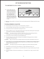
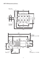
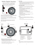
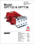
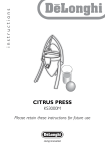
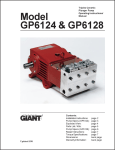
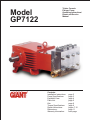
Model GP7122 Triplex Ceramic Plunger Pump Operating Instructions/ Repair and Service Manual Contents: Installation Instructions: Pump Specifications: Exploded View: Parts List: Kits: Torque Specifications: Repair Instructions: Dimensions: Warranty Information: page 2 page 3 page 4 page 5 page 6 page 6 pages 7-10 page 11 back page INSTALLATION INSTRUCTIONS 5. Use of a dampener is necessary to minimize pulsation at drive elements, plumbing, connections, and other system areas. The use of a dampener with Giant Industries, Inc. pumps is optional, although recommended by Giant Industries, Inc. to further reduce system pulsation. Dampeners can also reduce the severity of pressure spikes that occur in systems using a shut-off gun. A dampener must be positioned downstream from the unloader. Installation of the Giant Industries, Inc., pump is not a complicated procedure, but there are some basic steps common to all pumps. The following information is to be considered as a general outline for installation. If you have unique requirements, please contact Giant Industries, Inc. or your local distributor for assistance. 1. The pump should be installed flat on a base to a maximum of a 15 degree angle of inclination to ensure optimum lubrication. 6. Crankshaft rotation on Giant Industries, Inc. pumps should be made in the direction designated by the arrows on the pump crankcase. Reverse rotation may be safely achieved by following a few guidelines available upon request from Giant Industries, Inc. Required horsepower for system operation can be obtained from the chart on page 3. 2. The inlet to the pump should be sized for the flow rate of the pump with no unnecessary restrictions that can cause cavitation. Teflon tape should be used to seal all joints. If pumps are to be operated at temperatures in excess of 140o F, it is important to insure a positive head to the pump to prevent cavitation. 7 Before beginning operation of your pumping system, remember: Check that the crankcase and seal areas have been properly lubricated per recommended schedules. Do not run the pump dry for extended periods of time. Cavitation will result in severe damage. Always remember to check that all plumbing valves are open and that pumped media can flow freely to the inlet of the pump. IMPORTANT! To guarantee weep return, it is essential that the inlet line is fitted to the support screw (#62). If the inlet line is mounted to the other side of the pump, then the whole connection part (#s 62-62B, 64, 69-71) must be fitted to the same inlet side. 3. A tube fitting on the side of the pumphead which allows the circulation of water between the valve casing and seal sleeves to take place. The tube fitting must always be mounted on the same side as the suction line. Finally, remember that high pressure operation in a pump system has many advantages. But, if it is used carelessly and without regard to its potential hazard, it can cause serious injury. 4. The discharge plumbing from the pump should be properly sized to the flow rate to prevent line pressure loss to the work area. It is essential to provide a safety bypass valve between the pump and the work area to protect the pump from pressure spikes in the event of a blockage or the use of a shutoff gun. IMPORTANT OPERATING CONDITIONS Failure to comply with any of these conditions invalidates the warranty 2. Pump operation must not exceed rated pressure, volume, or RPM. A pressure relief device must be installed in the discharge of the system. 1. Prior to initial operation, add oil to crankcase so that the oil level is between the two lines on the oil dipstick. DO NOT OVERFILL. SAE 80 Industrial Gear oil may be used. Crankcase oil should be changed after the first 50 hours of operation, then at regular intervals of 500 hours or less depending on operating conditions. 3. Acids, alkalines, or abrasive fluids cannot be pumped unless approval in writing is obtained before operation from Giant Industries, Inc. 4. Run the pump dry approximately 10 seconds to drain the water before exposure to freezing temperatures. 2 Specifications Model GP7122 Volume ........................................................................................................ Up to 9.9 GPM Discharge Pressure ..................................................................................... Up to 10,000 PSI Speed .......................................................................................................... Up to 750 RPM Inlet Pressure .............................................................................................. Up to 90 PSI1 Plunger Diameter ........................................................................................ 22mm Plunger Stroke ............................................................................................ 48mm Crankshaft Diameter................................................................................... 48mm Key Width................................................................................................... 14mm Crankshaft Mounting .................................................................................. Either side Shaft Rotation ................................................................................ Top of pulley towards manifold Temperature of Pumped Fluids .................................................................. Up to 140 oF Inlet Ports ................................................................................................... (2) 1 1/4" BSP2 Discharge Ports........................................................................................... (2) 3/4" BSP3 Weight......................................................................................................... 374 lbs. Crankcase Oil Capacity .............................................................................. 1.6 Gal. Fluid End Material ..................................................................................... Stainless Steel Volumetric Efficiency @ 750 RPM............................................................ 89% Mechanical Efficiency @ 750 RPM........................................................... 83% Consult the factory for special requirements that must be met if the pump is to operate beyond one or more of the limits specified above. Positive inlet pressures are recommended! To convert to FNPT threads, add 13377-0100 (Adapter) and 13376-0100 (Seal) 3 To convert to FNPT threads, add 14081-0100 (Adapter) and 14082 (Seal) 1 2 90 Decibels 85 750 RPM 500 RPM 80 75 70 0 2900 5800 Pressure (PSI) 8700 11,600 NPSHR(FT-HEAD) Viscosity = 1 Centipoise System Requirements: No Unloader or Regulator allowed. Must use a safety valve and dump gun. 30 26 23 0 500 600 NPSHR Chart GP7122 HORSEPOWER REQUIREMENTS GPM 3000 PSI 5000 PSI 6000 PSI 7250 PSI 10000 PSI 4.0 8.6 14.3 17.1 20.7 28.6 5.3 11.4 18.9 22.7 27.4 37.9 7.3 15.6 26.1 31.3 37.8 52.1 7.9 16.9 28.2 33.9 40.9 56.4 8.6 18.4 30.7 36.9 44.5 61.4 9.2 19.7 32.9 39.4 47.6 65.7 9.9 21.2 35.4 42.4 51.3 70.7 HORSEPOWER RATINGS: The rating shown are the power requirements for the pump. Gas engine power outputs must be approximately twice the pump power requirements shown above. 90 85 Decibels RPM 300 400 550 600 650 700 750 700 RPM 80 75 70 0 2900 5800 Pressure (PSI) 8700 11,600 We recommend a 1.1 service factor be specified when selecting an electric motor as the power source. To compute specific pump horsepower requirements, use the following formula: GPM X PSI = hp 1400 3 Exploded View - GP7122 4 Must be on inlet connection side. See note on pg. 2. GP7122 PARTS LIST ITEM PART DESCRIPTION 1 07600 Crankcase 2 13000 4 QTY. ITEM PART DESCRIPTION 1 39B 06266 Support Ring 6 Oil Filler Plug Assembly 1 40 07338 Tension Spring 3 07601 Crankcase Cover 1 41 06753 Support Disc 3 5 07602 Seal for Crankcase Cover 1 42 06754 Spiral Ring (Packing) 6 8 07603 Oil Dip Stick 1 43 06755 Support Ring 6 9 06225 O-Ring, Dip Stick 1 44 06756 Guide Ring 3 10 13133 Hexagon Screw 12 45 06757 Pressure Ring 3 11 13134 Spring Washer 12 46 13390 Seal Ring 3 12 07606 Drain Plug 5 47 06758 Spacer Disc 3 13 07182 Gasket, Drain Plug 2 48 07690 Circlip 3 14 07607 Bearing Cover 2 49 13159 Stud Bolt 8 15 07608 Radial Shaft Seal 2 49A 13160 Hexagon Nut 8 16 07184 O-Ring for Bearing Cover 2 50 06759 Valve Casing 1 20 07610 Taper Roller Bearing 2 50A 13162 Centering Stud 2 20A 07611 Fitting Disc (Shim) 1-5 51A 12056 Support Ring 6 21 07612 Shaft Protector 1 51B 07354 O-Ring 6 22 13405 Crankshaft 1 51C 06760 Inlet Valve Seat 3 23 07614 Key 1 51D 06761 Valve Plate 6 24 13182 Connecting Rod Assy. 3 51E 06762 Valve Spring 6 25 13183 Crosshead Assy. 3 51F 06763 Spacer Pipe 6 28 13184 Crosshead Pin 3 52C 06764 Discharge Valve Seat 3 30 07619 Cover Plate 1 57 06078 Tension Spring 3 30A 07225-0100 Hexagon Screw 8 58 07699 Plug 3 30B 13136 Grommet 4 58A 07700 O-Ring 3 30C 07622 Disc 8 58B 07693 Support Ring 3 30D 13154 Cover 1 58C 07702 Hexagon Screw 12 31 07623 Eye Bolt 1 59A 07661 Copper Ring (Gasket) 3 32 07624 Radial Shaft Seal 3 60 13150 Plug 3/4 BSP 1 32A 07625 Seal Ring 3 61 13151 Plug 1-1/4 BSP 1 33 07626 Seal Retainer 3 62 06765 Connecting Screw 1 33A 07627 O-Ring for Seal Retainer 3 62A 06766 Connection Ring 1 33B 07628 Circlip for Seal Retainer 3 62B 06767 Seal Ring 2 34 13137 Oil Scraper (Flinger) 3 63 06589 Plug 1 36 06748 Plunger 3 64 07258-0100 Steel Ring 2 38 06749 Seal Sleave 3 66 13362 Disc for Crankshaft 1 38A 22764 Serrated Pin 3 67 13358 Hexagon Screw 1 38B 06750 Leakage Gasket 3 69 06588 Screw-in Connector 1 38C 06751 O-Ring 3 70 06768 Threaded Elbow 1 39 06752 Seal Case 3 71 06769 Curved Leakage Pipe 1 39A 07150 O-Ring 6 07704 Valve Tool (not shown) 1 5 QTY. GP7122 REPAIR KITS Plunger Packing Kit #09551 Item Part # Description 39A 07150 O-Ring 39B 06266 Support Ring 42 06754 Spiral Ring (Packing) 43 06755 Support Ring 44 06756 Guide Ring 46 13390 Seal Ring Oil Seal Kit #09225 Item Part # Description 32 07624 Radial Shaft Seal 32A 07625 Seal Ring 33A 07627 O-Ring Qty. 6 6 6 6 3 3 Qty. 3 3 3 Inlet Valve Assembly Kit #09552 Item Part # Description 51A 12056 Support Ring 51B 07354 O-Ring 51C 06760 Inlet Valve Seat 51D 06761 Valve Plate 51E 06762 Valve Spring Qty. 1 1 3 6 6 Discharge Valve Assembly Kit #09553 Item Part # Description Qty. 51A 12056 Support Ring 1 51B 07354 O-Ring 1 51D 06761 Valve Plate 1 51E 06762 Valve Spring 1 52C 06764 Discharge Valve Seat 1 GP7122 TORQUE SPECIFICATIONS Position Item# Description 24 36 49A 58C 13406 13138 13160 07702 Inner Hexagon Screw Plunger Nut Hexagon Screw Torque Amount 30 (ft.-lbs.) 33 (ft.-lbs.) 103 (ft.-lbs.) 155 (ft.-lbs.) 6 GP7122 REPAIR INSTRUCTIONS NOTE: Always take time to lubricate all metal and non-metal parts with a light film of oil before reassembling. This step will help ensure proper fit, at the same time protecting the pump non-metal parts (elastomers) from cutting and scoring. TO CHECK VALVES 58B 1) Lossen and remove screws (58C) with a 24mm socket wrench. 2) Take plugs (58) out of valve casing (50) by tightening screws (58C) against valve casing with two screws. 58A 57 3) Remove the compression spring (57) O-Ring (58A) and support ring (58B). 51C (Suction) 52C (Discharge) 4) Take out valve assemblies (52 & 51) using either tool (part #07704) or a stud bolt. 51E 51D 5) Valve seats (51C and 52C) are pressed out of spacer pipe (51F) by hitting the valve plate (51D) with a socket extention. 52C 51A 51B 6) Check surfaces of valve plate (51D), valve seat (51C or 52C), o-rings (51A), and support rings (51B). Replace worn parts. 7 GP7122 REPAIR INSTRUCTIONS Valve Seat identification markings 7) When reassembling: The inlet valve seat (51C) is 1mm smaller in diameter than the discharge valve seat (52C). Inlet valve seats are marked "S" and always have to be installed first. Discharge valve seats are marked "P" and are always to be installed on top of inlet valve. Plugs (58) are to be tensioned down evenly with screws (58C) and in crosswise pattern at 155 (ft.lbs.). TO CHECK SEALS 8) Loosen nuts (49A) with a 24mm socket wrench. 11) By gripping hex flats, separate plunger (36) from crosshead (25) by means of two open-end wrenches (size 22mm and 27mm). 9) With a rubber mallet tap the back of the valve casing (50) and pull the valve casing off the stud bolt (49). 12) Remove tension spring (40) from seal retainer (38). 8 10) Remove cover plate (30) with a 10mm socket wrench. 13) Pull seal sleeves (38) and plungers (36) out of their fittings in the crankcase (1) using ring groove as a guide. GP7122 REPAIR INSTRUCTIONS CAUTION: Don't loosen the 3 plunger (36) before the valve casing has been removed otherwise the plunger (36) could hit against the spacer pipe (51F) when the pump is being turned. 38A 38 14) Remove circlip ring (48) from seal sleeve (38). Remove spacer disc (47) and seal ring (46) from seal sleeve. Replace worn or damaged parts. 45 44 43 38C 38B 15) Remove leakage gasket (38B) from serrated pin (38A) on the seal sleave (38). Check o-ring (38C) for damage and replace if necessary. IMPORTANT! The 3.2 mm (diameter bore of the leakage gasket (38B) must be inserted directly on the serated pin (38A) of the seal sleeve (38). The leakage gasket must fit snugly to the seal so that the bevelled surface of the gasket faces outwords. 42 43 42 41 16) Remove support disc (41) seal unit (42, 43, 44) and pressure ring (45) of seal sleeve (38). Examine seals for signs of wear or cavitation, and if necessary, replace. NOTE: 36 33B 34 44 17) Examine plunger (36) for signs of wear or cavitation. If the surface of the plunger is worn, screw out the plunger with a 27mm tool. Clean centering and front surface of crosshead with plunger (25).Thread new plunger carefully through oiled seals in seal sleave. Coat thread of new plunger lightly with bonding agent (e.g., loctite). 9 Seal life can be increased if the pretensioning allows for a little leakage. This assists lubrication and keeps the seals cool. It is therefore not necessary to replace seals before the leakage becomes too heavy and causes output and operating pressure to drop. GP7122 REPAIR INSTRUCTIONS TO ASSEMBLE VALVE CASING 18. Check O-rings (39A) and support rings (39B) on seal case (39). Clean surfaces of seal sleeves (38) in crankcase (1) and sealing surfaces of valve casing (50). Insert seal sleeve with plunger into crankcase guide. Turn crankshaft to (22) until plunger with crosshead (25) pushes against plunger tighten plunger (36) to 26 ft-lbs. 39A 39B 39 39B 39A 19. Push valve casing carefully over O-rings of seal case and centering studs (50A). Tighten nuts (49A) to space 103 ft-lbs. TO DISASSEMBLE GEAR END 20. Take out plunger (36) and seal sleeves (38) as described above. Drain oil. 21. After removing the circlip ring (33B), pry out seal adapter (33) with a screw driver 22. Check seals (32,32A,33A) and surfaces of plunger base (25). 23. Remove crankcase cover (4). Loosen inner hexagon screws (24A) on the connecting rods (24) and push con rod halves as far into the crosshead guide as possible. CAUTION: Connecting rods (24) are marked for identification. Do not twist connecting rod halves. Connecting rod is to be reinstalled in the same position on crankshaft journals. 24. Check surfaces of the connecting rod (24) and crankshaft (22). 25. Take out bearing cover (14) to one side and push out crankshaft (22) taking particular care that the connecting rod (24) doesn't bend. CAUTION: Ring (32A) must always be installed so that the seal-lip on the inside diameter faces the oil. 26. Reassemble in reverse order: Regulate axial bearing clearance - minimum 0.1mm, maximum 0.15mm-by means of fitting disc (20A). The crankshaft (22) should turn easily with little clearance. Tighten inner hexagon screws (24A) to 30 ft.-lbs. CAUTION: Connecting rod (24) has to be able to be slightly moved sidewise at the stroke journals. 27. Reassemble cover (4) and seal (5) onto crankcase (1). Fasten with hexagon screws (10). 28. Reinstall shim (33C), and seal adaptor (33) with radial shaft seal (32), ring (32A) and o-ring (33A) onto crankcase (1). 29. Reinstall remainder of fluid end as described above in “To Assemble Valve Casing” section (21 and 22 above). 10 GP7122 Dimensions (Inches) 340 515 312.5 48kb 93 330 227 300 584 690 141.5 165 85 85.5 476.5 59 260 11 GIANT INDUSTRIES LIMITED WARRANTY Giant Industries, Inc. pumps and accessories are warranted by the manufacturer to be free from defects in workmanship and material as follows: 1. For portable pressure washers and car wash applications, the discharge manifolds will never fail, period. If they ever fail, we will replace them free of charge. Our other pump parts, used in portable pressure washers and in car wash applications, are warranted for five years from the date of shipment for all pumps used in NON-SALINE, clean water applications. 2. One (1) year from the date of shipment for all other Giant industrial and consumer pumps. 3. Six (6) months from the date of shipment for all rebuilt pumps. 4. Ninety (90) days from the date of shipment for all Giant accessories. This warranty is limited to repair or replacement of pumps and accessories of which the manufacturers evaluation shows were defective at the time of shipment by the manufacturer. The following items are NOT covered or will void the warranty: 1. Defects caused by negligence or fault of the buyer or third party. 2. Normal wear and tear to standard wear parts. 3. Use of repair parts other than those manufactured or authorized by Giant. 4. Improper use of the product as a component part. 5. Changes or modifications made by the customer or third party. 6. The operation of pumps and or accessories exceeding the specifications set forth in the Operations Manuals provided by Giant Industries, Inc. Liability under this warranty is on all non-wear parts and limited to the replacement or repair of those products returned freight prepaid to Giant Industries which are deemed to be defective due to workmanship or failure of material. A Returned Goods Authorization (R.G.A.) number and completed warranty evaluation form is required prior to the return to Giant Industries of all products under warranty consideration. Call (419)-531-4600 or fax (419)-531-6836 to obtain an R.G.A. number. Repair or replacement of defective products as provided is the sole and exclusive remedy provided hereunder and the MANUFACTURER SHALL NOT BE LIABLE FOR FURTHER LOSS, DAMAGES, OR EXPENSES, INCLUDING INCIDENTAL AND CONSEQUENTIAL DAMAGES DIRECTLY OR INDIRECTLY ARISING FROM THE SALE OR USE OF THIS PRODUCT. THE LIMITED WARRANTY SET FORTH HEREIN IS IN LIEU OF ALL OTHER WARRANTIES OR REPRESENTATION, EXPRESS OR IMPLIED, INCLUDING WITHOUT LIMITATION ANY WARRANTIES OR MERCHANTABILITY OR FITNESS FOR A PARTICULAR PURPOSE AND ALL SUCH WARRANTIES ARE HEREBY DISCLAIMED AND EXCLUDED BY THE MANUFACTURER. GIANT INDUSTRIES, INC. 900 N. Westwood Ave., P.O. Box 3187, Toledo, Ohio 43607 Phone: (419)-531-4600 FAX (419)-531-6836, www.giantpumps.com 9/01 GP7122.PM6 Ó Copyright 2001 Giant Industries, Inc.