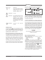
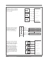
1
LDK 4502
HDTV Camera Base Station
User’s Guide
3922 496 48741 St.24
Declaration of Conformity
We, Thomson Broadcast Solutions Nederland B.V., Kapittelweg 10, 4827 HG Breda, The Netherlands declare under
our sole responsibility that this product is in compliance with the following standards:
: Safety
EN60065
EN55103-1 : EMC (Emission)
EN55103-2 : EMC (Immunity)
following the provisions of:
a. the Safety Directives 73/23//EEC and 93/68/EEC
b. the EMC Directives 89/336/EEC and 93/68/EEC
FCC Class A Statement
This product generates, uses, and can radiate radio frequency energy and if not installed and used in accordance with
the instructions, may cause interference to radio communications.
It has been tested and found to comply with the limits for a class A computing device pursuant to Subpart J of part 15
of FCC rules, which are designed to provide reasonable protection against such interference when operated in a commercial environment.
Operation of this product in a residential area is likely to cause interference in which case the user at his own expense
will be required to take whatever measures may be required to correct the interference.
Copyright
Für diese Unterlage behalten wir uns
alle Rechte vor (Gemäß DIN 34).
Technische Änderungen im Zuge der
Weiterentwicklung vorbehalten.
Copying of this document and giving
it to others, and the use or communication of the contents thereof,
are forbidden without express authority. Offenders are liable to the
payment of damages. All rights are
reserved in the event of the grant of
a patent or the registration of a utility
model or design. Liable to technical
alterations in the course of further
development.
© Thomson Multimedia Broadcast Solutions 2002
Toute communication ou reproduction de ce document, toute exploitation ou communication de son
contenu sont interdites, sauf autorisation expresse. Tout manquement à cette règle est illicite et
expose son auteur au versement de
dommages et intérêts. Tous nos
droits sont réservés pour le cas de la
délivrance d'un modèle d'utilité. Sous
réserve de modification au cours de
l'évolution technique.
HDTV
Camera
Base Station
User's Guide
Contents
About This Manual ........................................................ ii
Safety Instructions ................................................... 1-1
Safety Summary ........................................................ 1-2
Cautions and Warnings ............................................. 1-2
Earthing ..................................................................... 1-3
Installation ................................................................ 2-1
Unpacking/Transport/Storage ................................... 2-2
Dimensions ................................................................ 2-3
Connectors and Cables ............................................ 2-4
Intercom ................................................................... 2-14
Voice Mail ................................................................ 2-20
Private Data ............................................................. 2-21
MCP Available ......................................................... 2-22
Specifications .......................................................... 2-23
Operating Instructions ............................................. 3-1
Introduction ................................................................ 3-2
Front panel ................................................................ 3-3
Set-up ........................................................................ 3-4
Using the Menu System ............................................ 3-5
02.34.3
Menu System .......................................................... A3-1
System Menu Structure ........................................... A3-2
List of Abbreviations ................................................ A3-8
Replacements .......................................................... 4-1
Introduction ................................................................ 4-2
Power ......................................................................... 4-2
Opening The Base Station ........................................ 4-4
Replacing Dust Filters ............................................... 4-5
Diagnostics ............................................................... 5-1
Diagnostic LED Indications ....................................... 5-2
Triax diagnostic indications ....................................... 5-3
Board identification .................................................... 5-4
Sync/Encoder HD board status ................................. 5-5
Service Parts ............................................................ 6-1
Parts list & Exploded Views ....................................... 6-2
User's Guide LDK 4502 - HDTV Camera Base Station
i
About This Manual
Service policy
The Camera Base Station is a sophisticated base station
containing state-of-the-art electronic components which
are designed to provide long-life operation without the
need for maintenance. With this in mind, the service policy
of Thomson Multimedia Broadcast Solutions endeavours
to ensure that help will be quickly on hand in the unlikely
event of anything going wrong. The guiding principles of
the Thomson Multimedia Broadcast Solutions first line
maintenance philosophy are speed and cost effectiveness.
First line maintenance is dedicated to keeping your base
station operational, despite a fault, by module replacement
and the replacement of minor mechanical parts by the
user.
Purpose of this manual
The provision of correct information is the first step in
ensuring the operational integrity of the base station.
Information on the operation of the base station is contained
in Section 3 of the manual.
This User's Guide is an integral part of the service policy.
It ensures that you will be able to operate, install and setup your base station to meet the requirements of your
environment. The information on the installation of the
base station is contained in Section 2 of the manual. The
remaining sections of the manual provide first line service
information so that suitably qualified service personnel can
detect and repair faults, normally by module replacement.
Because of the complexity of some of the components,
second line service can only be carried out at the specially
equipped service centres and information concerning
second line maintenance is not supplied
in this manual.
Intended audience
The manual is intended as a guide to those with a working
knowledge of camera systems and installation techniques.
The first line detection and repair of faults requires a
general knowledge of test and measurement techniques.
Structure of this manual
The manual is divided into eight different sections:
Section 3: Operating instructions
Explains how to program the menu system for your personal
preferences. The menu structure and the methods of
function selection are also explained. An appendix to this
section lists all the menu functions.
Section 4: Replacements
Gives information on the replacement of components at
first line level.
Section 5: Diagnostics
Gives a guide to diagnostic messages and procedures for
fault-finding.
Identification and Status
To indicate the status of a drawing, a box with the numbers
0 to 9 is shown in the bottom-right of the drawing. The
number that is crossed-out is the status number of the
drawing. For example, in the illustration below, the status
is 1.
0 1 2 3 4
5 6 7 8 9
A sticker is used on the units themselves to identify them
and to indicate their status. For example, in the illustration
below, the top line is the 12-digit number that identifies the
unit type.
3922 406 88991
00121107 00 01
The first four digits of the number on the second line
represent a date code (year, week); the next four digits
represent the serial number for that week.
The number in the grey area indicates the status of the unit.
The last two digits represent the number that will be given
to the next status. However, if these two digits are contained
in a box, then this is the current status. For example, in the
illustration above, the current status of the unit is 01.
Section 1: Safety Instructions
Outlines the safety precautions that must be taken when
using the base station.
Section 2: Installation
Gives instructions on the integration of the base station into
the operating environment and the customization of certain
functions.
ii
User's Guide LDK 4502 - HDTV Camera Base Station
02.34.3
Section 1
Safety Instructions
This section outlines the precautions that must be taken into account when using the LDK 20(S)
Studio Camera.
Contents
Safety Summary ........................................................ 1-2
Cautions and Warnings ............................................. 1-2
Safety Instructions
Earthing ..................................................................... 1-3
User's Guide LDK 4502 - HDTV Camera Base Station
1-1
Safety Summary
Cautions and Warnings
This informaton is intended as a guide for trained and
qualified personnel who are aware of the dangers involved
in handling potentially hazardous electrical/electronic
equipment. It is not intended to contain a complete list of
all safety precautions which should be observed by
personnel in using this or other electronic equipment.
When performing service, be sure to read and comply with
the warning and caution notices appearing in the manuals.
Warnings indicate danger that requires correct procedures
or practices to prevent death or injury to personnel. Cautions
indicate procedures or practices that should be followed
to prevent damage or destruction to equipment or property.
The installation, maintenance and service of this equipment
involves risks both to personnel and equipment and must
be performed only by qualified personnel exercising due
care.
WARNING
Personnel engaged in the installation, operation,
maintenance or servicing of this equipment are urged to
become familiar with First Aid theory and practises.
During installation and operation of this equipment, local
building safety and fire protection standards must be
observed.
Before connecting the equipment to the power supply of
the installation, the proper functioning of the protective
earth lead of the installation needs to be verified.
Whenever it is likely that safe operation is impaired, the
apparatus must be made inoperative and secured against
any unintended operation. The appropriate servicing
authority must then be informed. For example, safety is
likely to be impaired if the apparatus fails to perform the
intended function or shows visible damage.
This product has been designed and tested according to
EN60065.
THE CURRENT AND VOLTAGES PRESENT IN THIS
EQUIPMENT ARE DANGEROUS. ALL PERSONNEL
MUST AT ALL TIMES FOLLOW THE SAFETY
REGULATIONS.
ALWAYS DISCONNECT POWER BEFORE REMOVING
COVERS OR PANELS.
ALWAYS DISCHARGE HIGH VOLTAGE POINTS
BEFORE SERVICING.
NEVER MAKE INTERNAL ADJUSTMENTS, PERFORM
MAINTENANCE OR SERVICE WHEN ALONE OR WHEN
FATIGUED.
IN CASE OF AN EMERGENCY ENSURE THAT THE
POWER IS DISCONNECTED.
ANY INTERRUPTION OF THE PROTECTION
CONDUCTOR INSIDE OR OUTSIDE THE APPARATUS,
OR DISCONNECTION OF THE PROTECTIVE EARTH
TERMINAL, IS LIKELY TO MAKE THE APPARATUS
DANGEROUS. INTENTIONAL INTERRUPTION IS
PROHIBITED.
FOR SAFETY REASONS THE CPU MUST BE MOUNTED
IN A 19-inch RACK WHICH HAS SAFETY COVERS
ACCORDING TO IEC65.
WHEN TWO CPUs ARE MOUNTED ABOVE EACH
OTHER THE MINIMUM DISTANCE BETWEEN THEM
MUST BE 50MM OR THE RACK MUST BE FORCE-AIR
COOLED.
USE ONLY FUSES OF THE TYPE AND RATING
SPECIFIED.
CAUTION
To prevent risk of overheating, ventilate the product
correctly.
Connect the product only to a power source with the
specified voltage rating.
Only connect a Triax cable from the LDK 6 camera
family to an LDK 6 CPU. Never connect it to any other
base station.
Never connect the Triax cable from a camera to a
CPU of a different family; never connect the LDK
family to the TTV family.
Do not allow system ground currents to exceed 1.5A
in the outer shield of the triax cable or 0.2A in other
cable shields.
It is strickly prohibited to short circuit the inner and
outer shields of a triax cable used to connect a
camera to a base station.
1-2
User's Guide LDK 4502 - HDTV Camera Base Station
Safety Instructions
Earthing
Symbol Colour
Red
The rear of a CPU has two separate screw terminals for
protective earth
(PE) and video earth
(VE).
Explanation
High voltage terminal at which a
voltage, with respect to an other
terminal, exists or may be
adjusted to 1000V or more.
VE
Metal
strap
PE
Yellow/Black
Live part.
Yellow/Black
This marking indicates that the
operator must refer to an
explanation in the Instruction
Manual, or that a specific
component must be replaced by
the component specified in the
documentation for safety
reasons.
White/Black
Protective
terminal.
earth
(ground)
Cathode ray tubes
Components marked
on the circuit diagram are critical
for safety and include those specified to comply with X-ray
emission standards for units using cathode ray tubes and
those specified for compliance with various regulations
regarding spurious radiation emission.
When servicing units that use cathode ray tubes (CRTs),
the cathode ray tubes themselves, the high voltage circuits
and related circuits are specifically chosen so that they
comply with recognized codes pertaining to X-ray emission.
Consequently, when servicing, replace the cathode ray
tubes and other parts with specified parts only. Do not
attempt to modify these circuits as any unauthorized
modification can increase the high voltage value and
cause X-ray emission from the cathode ray tube.
Handle the cathode ray tube only when wearing shatterproof
goggles and after discharging the high voltage completely.
Safety Instructions
These are normally connected by a metal strap. The
protective earth terminal is internally connected to the
protective earth conductor of the power cable. If required,
the central earth connection wire of the studio can be
connected to terminal PE.
In normal circumstances the connection between the
protective earth and the video earth should not be broken.
The metal strap may be removed only if the studio (or OB
van) is equipped with separate protective and video earth
systems. Under these circumstances the video earth
terminal must be connected to the central functional earth
potential (video earth) of the studio. This earth potential
should have functional protective and noiseless earth
(FPE) qualities as stated in the VDE regulation 0800/part2.
A low impedance interconnection of both earth conductors
must be provided at the central studio earthing point.
WARNING
THE UNIT MUST ALWAYS BE CONNECTED TO
PROTECTIVE EARTH.
Mains Lead Wiring for UK Users
The wires in the mains lead are coloured in accordance
with the following code:
GREEN AND YELLOW
EARTH
BLUE
NEUTRAL
BROWN
LIVE
As the colours of the wires in the mains lead of this
apparatus may not correspond with the coloured markings
identifying the terminals in your plug proceed as follows:
• The wire coloured GREEN AND YELLOW must be
connected to the terminal on the plug marked with the
or coloured
letter E or by the safety earth symbol
GREEN or GREEN AND YELLOW.
• The wire coloured BROWN must be connected to the
terminal marked with the letter L or coloured RED.
• The wire coloured BLUE must be connected to the
terminal marked with the letter N or coloured BLACK.
Ensure that your equipment is connected correctly - if you
are in any doubt consult a qualified electrician.
User's Guide LDK 4502 - HDTV Camera Base Station
1-3
1-4
User's Guide LDK 4502 - HDTV Camera Base Station
Safety Instructions
Section 2
Installation
This section provides information which is relevant when the base station is to be used for the first
time. Packing and unpacking instructions together with information on the integration of the base
station into your studio system are provided. The procedures for the customization of certain
hardware functions and connector information is also provided.
Contents
Unpacking/Transport/Storage ................................... 2-2
Dimensions ................................................................ 2-3
Connectors and Cables ............................................ 2-4
Intercom ................................................................... 2-14
Installation
Voice Mail ................................................................ 2-20
Private Data ............................................................. 2-21
MCP Available ......................................................... 2-22
Specifications .......................................................... 2-23
User's Guide LDK 4502 - HDTV Camera Base Station
2-1
Unpacking/Transport/Storage
Unpacking
Inspect the shipping container for evidence of damage
immediately after receipt. If the shipping container or
cushioning material is damaged, it should be kept until the
contents of the shipment have been checked for
completeness and the units have been checked
mechanically and electrically.
If the original packing can no longer be used, the following
general instructions should be used for repacking with
commercially available materials:
a. Wrap unit in heavy paper or plastic.
b. Use strong shipping container.
The shipping container should be placed upright and
opened from the top.
Remove the cushioning material and lift out the contents.
The contents of the shipment should be checked against
the packing list. If the contents are incomplete, if there is
mechanical damage or defect, or if the units do not perform
correctly when unpacked, notify your Thomson Multimedia
Broadcast Solutions sales or service centre within eight
days. If the shipping container shows signs of damage or
stress, notify the carrier as well.
d. Seal shipping container securely.
e. Mark shipping container FRAGILE to ensure careful
handling.
Storage
The unit may be stored (non-operating condition) in
environments within the following limits:
Transport
If a unit is being returned to Thomson Multimedia Broadcast
Solutions for servicing, try to use the containers and
materials of the original packaging. Attach a tag indicating
the type of service required, return address, model number,
full serial number and the return number which will be
supplied by your Thomson Multimedia Broadcast Solutions
service centre.
2-2
c. Use a layer of shock-absorbing material around all
sides of the unit to provide firm cushioning and prevent
movement inside container.
Temperature:
-40oC to +70oC
Humidity:
Max. 90% (non condensing)
Altitude:
max. 50.0000 feet
When stored, the unit should be protected from temperarure
extremes which may cause condensation, and should also
be protected from high levels of dust.
User's Guide LDK 4502 - HDTV Camera Base Station
Installation
Dimensions
Dimensions:
Width:
Height:
Depth:
438 mm
88 mm
510 mm max. (excluding triax connector + cable)
Weight: approx. 17kg.
483 mm
465 mm
Prod
HDTV
Prog
Cam +Floor
Eng
Camera
Communication
On Air
Base
Station
Camera
Test Connected
Camera Base Station
57
mm
88 mm
438 mm
510 mm
Installation
User's Guide LDK 4502 - HDTV Camera Base Station
2-3
Connectors and Cables
Data1
I / Com
Sign
Data2
WFM
HD SDI
External
1
R
1
2
G
2
3
B
3
TP
230
Aux
SDI
1
PXM
1
RS232
2
2
Link
Ref
CVBS
Text
Audio out
Triax connector orientation
The triax connector can be mounted to suit your cable
run.
2-4
User's Guide LDK 4502 - HDTV Camera Base Station
Installation
Intercom Connector (I/Com) - Panel View
15-pin female, shielded cable
1.
2.
3.
4.
5.
6.
7.
8.
9.
10.
11.
12.
13.
14.
15.
8
15
9
1
Prod. out (4-wire out, 2-wire in/out)
Prod. in (4-wire only)
Prod. in shield (4-wire only)
ENG in (4-wire only)
ENG out (4-wire out, 2-wire in/out)
Progr. in (4-wire only)
Progr. in shield (4-wire only)
Housing
prod. out return (4-wire out, 2-wire in/out)
prod. in return (4-wire only)
ENG in shield (4-wire only)
ENG in return (4-wire only)
ENG out return (4-wire out, 2-wire in/out)
Progr. in return (4-wire only)
Housing
Shield of cable to the pin marked housing.
4-wire:
X374
15-pin female
Panel part number
Cable part number
2411 022 06239
2411 022 05168
2 - Wire configuration
15
Housing
Output signals:
level +6dBu or 0dBu selectable output
impedance 50 ohm (max), symmetrical
Input signals:
level +6dBu or 0dBu selectable
impedance 9 Kohm (min), symmetrical
2-wire:
level 0dBu
load impedance: 200 ohm
maximum DC level = 40 V
8
(+)
(-)
(-)
ENG in/out
0dB
Z=200 ohm
Max 40V DC
(+)
(-)
PROD in/out
9
(+)
1
4 - Wire configuration
Housing
15
8
PROG in
ENG out
ENG in
PROD in
PROD out
+6 dB or 0dB
Zin > 9 k ohms
Installation
9
1
User's Guide LDK 4502 - HDTV Camera Base Station
+6dB or 0dB
Zout < 50 ohms
2-5
RS232 Connector (RS232) - Panel View
1. SPARE
9
6
5
1
2. RS-RXD
-
Receive Data
3. RS-TXD
-
Transmit Data
4. RS-DTR
-
Data Terminal Ready
5. RS-DGND -
Signal Ground
6. RS-DSR
-
Data bSet Ready
7. RS-RTS
-
Request To Send
8. RS-CTS
-
Clear To Send
9. +12V
X7 Data Board
9-pin male
X379 Signal Connector Board
Panel part number
2422 025 12962
Serial Interface Cable 4822 872 03413
2-6
User's Guide LDK 4502 - HDTV Camera Base Station
Installation
Auxiliary Connector (Aux) - Panel View
9-pin female, shielded cable
1. +5V
9
5
2. AN 0
3. PRIVATE DATA OUT
4. PRIVATE DATA IN
6
5. Housing (Shield of cable to this pin)
1
6. GND
7. AN 1
8. PRIVATE DATA OUT RET
9. PRIVATE DATA IN RET
Shield of cable directly to the connector housing.
X371
9-pin female
Panel part number
Cable part number
2411 022 06238
2411 022 05284
AUX (private data BS - CAM)
: "0"= 0V +/- 0.5V
5
: "1"= 5V +/- 0.5V
9
PRIVATE DATA IN
Rout = 150 ohm
Baudrate typ
2400 bits/sec
max 4800 bits/sec
Duty cycle difference between input and output is max 5%
6
1
PRIVATE DATA OUT
Installation
User's Guide LDK 4502 - HDTV Camera Base Station
2-7
Signalling Connector (Sign) - Panel View
15-pin male, shielded cable
1. Prev. out ext. (relay contact < 10 ohm)
2. Call out ext. (relay contact < 10 ohm)
3. Iso in ext. (dry contact)
1
9
4. On-Air in ext (dry contact)
5. Call in ext. (dry contact)
6. Audio 1 level (analogue input voltage 0V to
+5V, see figure below)
15
-
8
64
58
52
46
40
34
28
22
dB
dB
dB
dB
dB
dB
dB
dB
-----------------------------------------
0V
+0.7V
+1.3V
+1.9V
+2.5V
+3.1V
+3.7V
+4.3V
7. +5 Vdc; OCP
X 370
15-pin male; panel view
8. Housing
Panel part number
Cable part number
2411 022 05292
2411 022 06157
9. Prev. out ext. return
10. Call out ext. return
11. Iso in ext. return
12. On-Air in ext. return
13. Call in ext. return
14. Audio 2 level (see pin 6)
15. GND
Shield of cable to the pin marked housing.
9
1
Preview out
Call out
Iso in
On Air in
Call in
+5V
GND
15
Housing
8
Audio 2 input sensitivity
2-8
-22dB
1k
-28dB
1k
-34dB
1k
-40dB
1k
-46dB
1k
-52dB
1k
-58dB
1k
-64dB
1k
User's Guide LDK 4502 - HDTV Camera Base Station
Installation
When the Iso, On-Air or Call signal is
provided by a dry contact, connect the
outputs to the signalling connector as
shown in this figure.
Iso 1a
External Iso
signaling
dry contact
Iso 1b
On-Air (Tally) 1a
External On-Air
signaling
dry contact
On-Air (Tally) 1b
Call 1a
External Call
signaling
dry contact
Call 1b
Iso in ext. (PIN3)
Iso in ext. Return (PIN11)
On-Air in ext. (PIN4)
On-Air in ext. Return (PIN12)
Call in ext. (PIN5)
Call in ext. Return (PIN13)
X 370 Signalling Connector
When the Iso, On-Air or Call signal
is provided by a dry contact with a
common return connector connect
the outputs to the signalling
connector as shown in this figure.
On-Air (Tally) 1
On-Air in ext. (PIN4)
On-Air in ext. Return (PIN12)
X 370 Signalling Connector
Base Station 1
On-Air (Tally) 2
On-Air in ext. (PIN4)
On-Air in ext. Return (PIN12)
X 370 Signalling Connector
Base Station 2
On-Air (Tally) n
On-Air in ext. (PIN4)
On-Air in ext. Return (PIN12)
Common
X 370 Signalling Connector
Base Station n
External On-Air
signaling with
common contact
When the Iso, On-Air or Call signal
is provided by a DC output voltage
connect the outputs to the signalling
connector as shown in this figure.
Notes: The Iso, On-Air and Call
signal is off if the input voltage is
5..24 VDC. The Iso, On-Air and Call
signal is on if the input voltage is
0VDC. The X370 Signalling inputs
are not galvanically separated. We
recommend using dry contacts and
when these are not available using
galvanically separated DC voltage
outputs.
Iso 1a
+
External
Iso signaling
with DC
+5.24 VDC
Output
Voltage
On-Air (Tally) 1a
+
External
On-Air
signaling
with DC
Output
Voltage
Iso 1b
Iso in ext. (PIN3)
Iso in ext. Return (PIN11)
On-Air in ext. (PIN4)
+5.24 VDC
On-Air (Tally) 1b
+
External
Call signaling
with DC
+5.24 VDC
Output
Voltage
Call 1a
Call 1b
On-Air in ext. Return (PIN12)
Call in ext. (PIN5)
Call in ext. Return (PIN13)
X 370 Signalling Connector
Installation
User's Guide LDK 4502 - HDTV Camera Base Station
2-9
Audio Connector - Panel View
1. shield
1
2
2. Audio +
3. Audio -
Microphone impedance >200 ohm
3
Sensitivity remote controlled via base station:
range: -64 to -22 dBu.
Shield of cable directly to the connector housing.
X338/X339
XLR 3-pin male
Panel part number
Cable part number
2422 026 02985
2432 026 00185
Data Connector - Panel View
A
4-pin male, shielded cable
A. Data
D
B. Data not
C. Not connected
B
D. Shield
Shield of cable to the pin marked housing.
C
X368 / X378
4-pin male
Panel part number
Cable part number
2411 020 11367
2411 020 12025
2-10
User's Guide LDK 4502 - HDTV Camera Base Station
Installation
Mains Input Connector - Panel View
Eurostyle 3-pin male
230
1. Neutral
2. Line
3. Earth
Mains input voltage: 230 Vac or 115 Vac
1
2
Fuses:
4AT
Mains frequency:
10AT
47 to 63 Hz
Power consumption: 320 Watt
3
Link Connector - Panel View
3-pin female, shielded cable
1
1. Data link
2. Data link N
2
3. Housing
3
Shield of cable to the pin marked housing.
FOR FUTURE USE ONLY
X380
Fischer 3-pin female
Panel part number
Cable part number
3922 040 02881
2432 026 00274
Installation
User's Guide LDK 4502 - HDTV Camera Base Station
2-11
Headset Connectors - Panel View
Headset Connector
6
Tuchel 5-pin female
5
1. Telephone left
2
1
2. Telephone return
3. Microphone
4. Microphone return
5/6.Telephone right
4
3
X574
Panel part number
Cable part number
Shield of cable directly to the connector housing.
Tuchel 5-pin female
Tuchel 6-pin female
1. Telephone left
6
1
2. Telephone return
3. Microphone
4. Microphone return
5
2
5. Telephone right
6. Telephone return
4
3
Shield of cable directly to the connector housing.
X574
Panel part number
Cable part number
Tuchel 6-pin female
XLR 5-pin female
1. Microphone return
2. Microphone
5
1
3. Telephone return
4. Telephone left
4
5. Telephone right
2
3
Microphone level -64dBu
Microphone impedance 200 ohm
X574
Panel part number
Cable part number
XLR 5-pin female
2422 026
Telephone level +6dBm nominal
Telephone output impedance <50 ohm
Shield of cable directly to the connector housing.
6
1
XLR 7-pin female
1. not connected
5
2
2. Return
3. ENG Telephone right
4
3
7
4. Return
5. ENG Telephone left
6. Return
X574
Panel part number
Cable part number
2-12
XLR 7-pin female
3922 494 16571
7. ENG Microphone
User's Guide LDK 4502 - HDTV Camera Base Station
Installation
Triax Connectors - Panel View
Triax Connectors
Fischer
3
1. Inner pin:
Signals + power
2. Inner shield:
Return
3. Outer shield:
Base Station housing
Trilock
2
1. Inner pin:
Signals + power
2. Inner shield:
Return
3. Outer shield:
Base Station housing
ARD
1
1. Inner pin:
Signals + power
2. Inner shield:
Return
3. Outer shield:
Base Station housing
Lemo 3
X540
Fischer male
Panel part number
3922 407 30531
X540
Trilock female
Panel part number
3922 407 30551
X540
ARD female
Panel part number
3922 407 30571
X540
LEMO 3 female
Panel part number
3922 407 30631
X540
LEMO 4 female
Panel part number
3922 407 30591
Lemo BBC
X540
LEMO BBC male
1. Inner pin:
Signals + power
Panel part number
3922 407 30611
2. Inner shield:
Return
3. Outer shield:
Base Station housing
1. Inner pin:
Signals + power
2. Inner shield:
Return
3. Outer shield:
Base Station housing
Lemo 4
The panel partnumbers are the connectors including the
assembly.
Installation
1. Inner pin:
Signals + power
2. Inner shield:
Return
3. Outer shield:
Base Station housing
User's Guide LDK 4502 - HDTV Camera Base Station
2-13
Intercom
The intercom functions available are determined by the
configuration of the base station. The Headset board and
the Audio/Intercom board are optional. This results in four
possible configurations:
1. Headset board present - Audio/Intercom board absent
2. Headset board absent - Audio/Intercom board present
3. Both boards present
4. Both boards absent
If both boards are absent then there are no intercom
facilities available. The other configurations are shown in
the figures below.
Depending on your camera configuration, consult the
cross-reference tables to see which menu positions should
be used for both camera and base station menus for
routing the intercom signals.
Headset board present - Audio/Intercom board absent in Base Station
1. Headset board present - Audio/Intercom board absent
Camera Headset
No Intercom Lines
Clear A 1 Clear
Star 4P B 2 ND1/4
Star 6P C 3 ND1/16
Smart
card
Soft Focus D 4 ND1/64
VTR
Save
P
Std.
File
Ext.
Iris
wel
Aux
Tracker
er
Pow on
ENG
Prod
HDTV
Prog
Cam +Floor
Eng
Camera Base Station
Tracker
(Floor)
ENG
CAM
Tracker
CAM
Tracker
(Floor)
ENG-Cam
Studio
Intercom
Tracker
(Floor)
CAM
Intercom selection switch
Prod
Prog
Cam +Floor
Eng
Tracker Headset
2-14
BS Headset
User's Guide LDK 4502 - HDTV Camera Base Station
Cam + Floor position
Installation
Headset board present - Audio/Intercom board absent in Base Station
TO
Tracker Headset
Camera Headset
BS Headset
FROM
Tracker Mic
(Phantom Power !)
Tracker Output = ENG Channel
Camera system menu:
Install \ Intercom \ Track mic to ¹ Off
Install \ Intercom \ Track Source = Side
Camera system menu:
Install \ Intercom \ Track mic to ¹ Off
Install \ Intercom \ Cam track ¹ Off
Install \ Intercom \ Cam level > 0
Camera system menu:
Install \ Intercom \ Track mic to ¹ Off
BS system menu:
Audio/Intercom \ ENG headset \ Tracker
to headset = On
Audio/Intercom \ ENG headset \ Tracker
volume > 0
BS front:
Intercom selection switch = Cam + Floor
Camera Mic
(Phantom Power !)
CAM Channel
Tracker Output = Camera Channel
Cam Mic = On*
Camera system menu:
Install \ Intercom \ Cam Mic to = CH1
Camera system menu:
Install \ Intercom \ Cam Mic = On
Install \ Intercom \ Side tone > 0
Camera system menu:
Install \ Intercom \ Cam mic to = CH1
(If = CH2, then monitoring via floor)
BS system menu:
Audio/Intercom \ ENG headset \ Cam to
headset = On
Audio/Intercom \ ENG headset \ Cam
volume > 0
Audio/Intercom \ ENG headset \ Floor to
headset = On
BS front:
Intercom selection switch = Cam + Floor
ENG Channel
Tracker Output = ENG Channel
Camera system menu:
Install \ Intercom \Track Source = Side
Install \ Intercom \ Cam Mic to = Ch2
BS Headset Mic
(Phantom Power !)
Tracker Output = ENG Channel
Camera system menu:
Install \ Intercom \ Track Source = ENG
BS system menu:
Audio/Intercom \ ENG Headset \ Mic to
ENG-Cam = On
Camera system menu:
Install \ Intercom \ Cam engineering ¹ Off
BS system menu:
Audio/Intercom \ ENG Headset \ Mic to
ENG-Cam = On
BS system menu:
Audio/Intercom \ ENG headset \ Sidetone
>0
* Other ways to switch on camera microphone:
• Camera: Start button = On
• Camera: Intercom Routing Switch = ENG or PROD
Installation
User's Guide LDK 4502 - HDTV Camera Base Station
2-15
Audio/Intercom board present - Headset board absent in Base Station
2. Headset board absent - Audio/Intercom board present
Camera Headset
Clear A 1 Clear
PROD
ENG
PROG
Star 4P B 2 ND1/4
Star 6P C 3 ND1/16
Soft Focus D 4 ND1/64
VTR
Save
Std.
File
Smart
card
Ext.
Iris
l
P
we
Aux
Tracker
er
Pow on
PROD
ENG
PROG
HDTV
Studio
Intercom
Camera Base Station
PROD
ENG
PROG
Tracker
(Floor)
ENG
PROD
CAM
Tracker
(Floor)
PROD
ENG
Tracker
Tracker Headset
2-16
User's Guide LDK 4502 - HDTV Camera Base Station
Installation
Installation
User's Guide LDK 4502 - HDTV Camera Base Station
2-17
Tracker box = ENG Channel
Camera system menu:
Install \ Intercom \Track Source =
ENG
Tracker box = PROG Channel
Studio ENG
Studio PROG
* Other ways to switch on camera microphone:
• Camera: Start button = On
• Camera: Intercom Routing Switch = ENG or PROD
Tracker box = PROD Channel
Studio PROD
ENG Channel
Tracker box = ENG Channel
Camera system menu:
Install \ Intercom \Track Source =
Side
Install \ Intercom \ Cam Mic to =
Ch2
CAM Channel
Tracker box = Camera Channel
Cam Mic = On*
Camera system menu:
Install \ Intercom \ Cam Mic to =
CH1
Camera Mic
(Phantom Power !)
Tracker Headset
Tracker box = ENG Channel
Camera system menu:
Install \ Intercom \ Track mic to ¹
Off
Install \ Intercom \ Track Source =
Side
TO
Tracker Mic
(Phantom Power !)
FROM
Camera system menu:
Install \ Intercom \ Cam program ¹
Off
Camera system menu:
Install \ Intercom \ Cam engineering
¹ Off
Camera system menu:
Install \ Intercom \ Cam production
¹ Off
Camera system menu:
Install \ Intercom \ Cam Mic = On
Install \ Intercom \ Side tone > 0
Camera system menu:
Install \ Intercom \ Track mic to ¹
Off
Install \ Intercom \ Cam track ¹ Off
Install \ Intercom \ Cam level > 0
Camera Headset
Not available
Not available
Not available
BS system menu:
Audio/Intercom \ Intercom \ Isolate \
Isolate = Syst
Camera intercom routing switch =
Prod
(or camera start button = on)
Camera system menu:
Install \ Intercom \ Track mic to = All
or Prod
BS system menu:
Audio/Intercom \ Intercom \ Isolate \
Isolate = Syst
Studio PROD
Audio/Intercom board present - Headset board absent in Base Station
Not available
Not available
Not available
BS system menu:
Audio/Intercom \ Intercom \ Isolate \
Isolate = Syst
Camera intercom routing switch =
ENG
Camera system menu:
Install \ Intercom \ Track mic to = All
or ENG
BS system menu:
Audio/Intercom \ Intercom \ Isolate \
Isolate = Syst
Studio ENG
Audio/Intercom board and Headset board present in Base Station
3. Headset board present - Audio/Intercom board present
Camera Headset
Star 6P C 3 ND1/16
VTR
Save
P
Std.
File
we
Smart
card
Ext.
Iris
l
Aux
PROG
PROD
ENG
PROG
PROD
ENG
Clear A 1 Clear
Star 4P B 2 ND1/4
Soft Focus D 4 ND1/64
Tracker
er
Pow on
Prod
HDTV
Prog
Cam +Floor
Eng
Camera Base Station
PROG
PROD
ENG
CAM
Tracker
(Floor)
CAM
Tracker
(Floor)
PROD
ENG
ENG-Cam
Studio
Intercom
ENG-Out
Tracker (Floor)
CAM
Tracker
Tracker Headset
2-18
BS Headset
User's Guide LDK 4502 - HDTV Camera Base Station
Installation
Installation
User's Guide LDK 4502 - HDTV Camera Base Station
2-19
BS front:
Intercom selection switch = ENG
BS front:
Intercom selection switch = PROG
Camera system menu:
Install \ Intercom \ Cam Engineering ¹ Off
Camera system menu:
Install \ Intercom \ Cam Program ¹ Off
Tracker box = ENG Channel
Tracker box = PROG Channel
Studio ENG
Studio PROG
* Other ways to switch on camera microphone:
• Camera: Start button = On
• Camera: Intercom Routing Switch = ENG or PROD
BS front:
Intercom selection switch = PROD
Camera system menu:
Install \ Intercom \ Cam Production ¹ Off
Tracker box = PROD Channel
Studio PROD
BS system menu:
Audio/Intercom \ ENG headset \ Cam to
headset = On
Audio/Intercom \ ENG headset \ Cam
volume > 0
Audio/Intercom \ ENG headset \ Floor to
headset = On
BS front:
Intercom selection switch = Cam + Floor
Camera system menu:
Install \ Intercom \ Cam mic to = CH1
(If = CH2, then monitoring via floor)
Camera system menu:
Install \ Intercom \ Track mic to ¹ Off
BS system menu:
Audio/Intercom \ ENG headset \ Tracker
to headset = On
Audio/Intercom \ ENG headset \ Tracker
volume > 0
BS front:
Intercom selection switch = Cam + Floor
BS Headset
BS system menu:
Audio/Intercom \ ENG headset \ Sidetone
>0
Camera system menu:
Install \ Intercom \ Cam Mic = On
Install \ Intercom \ Side tone > 0
Camera system menu:
Install \ Intercom \ Track mic to ¹ Off
Install \ Intercom \ Cam track ¹ Off
Install \ Intercom \ Cam level > 0
Camera Headset
Camera system menu:
Install \ Intercom \ Cam Engineering ¹ Off
BS system menu:
Audio/Intercom \ ENG Headset \ Mic to
ENG-Cam = On
ENG Channel
Tracker box = ENG Channel
Camera system menu:
Install \ Intercom \Track Source = Side
Install \ Intercom \ Cam Mic to = Ch2
CAM Channel
Tracker box = Camera Channel
Cam Mic = On*
Camera system menu:
Install \ Intercom \ Cam Mic to = CH1
Tracker box = ENG Channel
Camera system menu:
Install \ Intercom \ Track mic to ¹ Off
Install \ Intercom \ Track Source = Side
Tracker Headset
Tracker box = ENG Channel
Camera system menu:
Install \ Intercom \ Track Source = ENG
BS system menu:
Audio/Intercom \ ENG Headset \ Mic to
ENG-Cam = On
TO
BS Headset Mic
(Phantom Power !)
Camera Mic
(Phantom Power !)
Tracker Mic
(Phantom Power !)
FROM
Audio/Intercom board and Headset board present in Base Station
Not available
Not available
Not available
Not available
BS system menu:
Audio/Intercom \ Isolate \ Isolate ¹
Isol
Camera intercom routing switch =
PROD
Camera system menu:
Install \ Intercom \ Track mic to = All
(or Prod)
BS system menu:
Audio/Intercom \ Isolate \ Isolate ¹
Isol
Studio PROD
Not available
Not available
Not available
BS system menu:
Audio/Intercom \ Isolate \ Isolate ¹
Isol
Audio/Intercom \ ENG Headset \ Mic
Eng-Out = On
BS system menu:
Audio/Intercom \ Isolate \ Isolate ¹
Isol
Camera intercom routing switch = ENG
Camera system menu:
Install \ Intercom \ Track mic to = All
(or Eng)
BS system menu:
Audio/Intercom \ Isolate \ Isolate ¹
Isol
Studio ENG
Voice Mail
Camera Headset
Intercom
PROD Channel
ENG
PROD
Record ENG
Record PROD
Clear A 1 Clear
Soft Focus D 4 ND1/64
VTR
Save
P
Std.
File
we
Record PROG
Play
Star 4P B 2 ND1/4
Star 6P C 3 ND1/16
Smart
card
Ext.
Iris
Aux
PROD
Voice Mail
l
Tracker
er
Pow on
PROG
Start playing the recorded Voice Mail with the
Call button
Voice Mail is an intercom message storage function.
Note: Voice mail is only available if the Base Station menu
item Audio/Intercom \ Intercom \ Call is set to Voice.
Recording
Recording starts automatically at the start of a message. A
new message erases the previous recorded message. The
maximum message length is 16 seconds. Longer messages
are recorded in a retroloop. Only the last 16 seconds are
available for playback.
Station menu items Audio/Intercom \ Intercom \ Voice mail
\ Record ENG, PROD and PROG.
Note: The voice mail box can only contain one message.
If voice mail recording starts from an other intercom
channel the previous message is erased.
Listening to the message
Push the camera call button to start playing out the recorded
voice mail to the camera headset. Push the call button
again to stop playing the voice mail message.
Select the intercom channels to be recorded via the Base
2-20
User's Guide LDK 4502 - HDTV Camera Base Station
Installation
Private Data
Clear A 1 Clear
Star 4P B 2 ND1/4
Star 6P C 3 ND1/16
Soft Focus D 4 ND1/64
VTR
Save
Std.
File
Smart
card
Ext.
Iris
l
P
we
Aux
Tracker
er
Pow on
Tracker Channel
Triax Cable
HDTV
CTL
Camera Base Station
PROG Channel
Tracker Channel
A Control is as an example
connected to the Aux
connector.
PROG Channel
P&T
A pan and tilt unit as an example
connected to the Aux connector.
Private data channels can be used for the transmission of
serial data via the triax cable. For example, electronic
scriptboard or character data for a video display unit can be
transmitted to the camera.
The tracker microphone intercom channel is used for the
data channel from camera head to Base Station. The
program intercom channel is used for the data channel
from Base Station to camera head. The input and output
signals are available on the auxiliary connectors of the
camera and Base Station (for camera see the connectors
and cables section). If a channel is used for private data,
then of course the original functions are no longer available.
To select the function of the Base Station to camera
channel set the Base Station menu item Audio/Intercom \
Private Data \ PROG Channel to Priva.
Installation
To select the function of the Camera to Base Station
channel set the Base Station menu item Audio/Intercom \
Private Data \ Tracker Channel to Priva.
Remember that the propagation-delay times are different
for different triax cable lengths, especially if a return signal
is involved. At maximum lengths of 2400 metres the total
delay is at least 25 µsec. and can be more than 30 µsec,
depending on the type of triax cable.
Data signal specifications
Baudrate: 2400
Input level: TLL, possible RS232
Input impedance: 100Kohm
Output impedance: ~300 ohm
Max load: ~1Kohm
User's Guide LDK 4502 - HDTV Camera Base Station
2-21
MCP Available
When no MCP is available it might occur that some
functions are in an undesirable position, for example, a lock
on the upper part of the OCP. To prevent this happening,
set the Base Station menu item System \ MCP Available to
No when an MCP is not available.
The functions affected by this setting and their state are as
follows (if the item value is set to MCP Available = No):
Variable black stretch (Yes/No)
Variable gamma (Yes/No)
Variable Flare (Yes/No)
Saturation (Yes/No)
White clipper (Yes/No)
Knee slope (Yes/No)
Knee point (Yes/No)
Iris(Normal/Reverse)
OCP lock (Upper/Total)
Intercom (System/Isolate)
Audio (External/MCP)
Aspect Ratio (External/MCP)
Aspect Ratio (4:3/16:9)
Autolight (Yes/No)
Yes
Yes
Yes
Yes
Yes
Yes
Yes
Normal
Total
System
External
External
4:3
Yes
2-22
User's Guide LDK 4502 - HDTV Camera Base Station
Installation
Specifications
LDK 4502/00
HDTV Base Station
General
Dimensions (WxHxD)
438 (19" rack) x 88 (2RU) x510mm.
(17.2 x 3.5 x 20.1 inch)
Operating temperature -20 °C to +50 °C (-4 °F to 122 °F)
Storage temperature -40 °C to +70 °C (-40 °F to 158 °F)
Operating humidity
Max. 90% (non condensing)
Shock resistance
Max.10G (transport), Max. 2G (operating)
Altitude
Max. 50,000 ft
Weight
17.0 kg. ( 37.5 lbs.) fully equipped with
options
Transmission
Typical. cable length
Bandwidth
Connectors
Teleprompter in
Reference in
HD-SDI out
Text out
Composite video out
Signalling in/out
Auxiliary in/out
RS-232
Control data
Link
1,000 m. (3,281 ft) (14 mm./0.55" triax
cable)
30/ 15/ 15 MHz., Y/Cr/Cb
BNC 1x (and loop-through output),
1.0Vp-p, 75W
BNC 1x (and loop-through output),
1.0Vp-p, 75WHD tri-level sync or SD Black
Burst
BNC 3x, 0.8Vp-p, 75 W, SMPTE 292M,
1080i or 720p at 59.94 or 50Hz
BNC 1x, 1.0Vp-p, 75 W(VBS)
BNC 1x, 1.0Vp-p, 75 W(CVBS, w/ or w/o
text, for viewing purposes)
D-sub 15-pin, male
Preview, Green tally (call), dry contact,
Yellow tally (ISO), dry contact
Red tally (on-air), dry contact
Remote audio level control (22-64dB),
DC
D-sub 9-pin, female
An0, 0-5Vdc in, output on camera head
An1, 0-5Vdc in,
16:9 < 0.8 Vdc in, 4:3 > 2.4Vdc i n
Private data in/ out, 2.4kB TTL (RS-232)
D-sub 9-pin, male (RXD, TXD, DTR, DSR,
RTS, CTS)
4- pin, male (2-wire camera control bus)
3- pin, female (Feature box control link)
LDK 4510 POWER MODULES
LDK 4510/10
AC/DC power module for studio and
portable camera heads
Power requirement
AC 115V/230V +/- 15%, 47 to 63Hz
Power connector
IEC type, 3-pin male
Power consumption
470VA or 270Watts max. with studio
camera head; 360VA or 210Watts max.
with port. camera head
Utility power
150VA or 150Watts max. on studio camera
head; 80VA or 80Watts max. on port.
camera head
LDK 4521 HDTV TRIAX MODULES
LDK 4521/10
TriaxHD Module with Fischer triax
connector
LDK 4521/20
TriaxHD Module with Tri-Lock triax
connector
LDK 4521/30
TriaxHD Module with ARD triax connector
LDK 4521/40
TriaxHD Module with Lemo 4 triax
connector
LDK 4521/50
TriaxHD Module with Lemo BBC triax
connector
LDK 4521/60
TriaxHD Module with Lemo 3 triax
connector
Installation
LDK 4530 EXTERNAL VIDEO IN MODULES
LDK 4530/10
External video input module
External video in
BNC 2x, 1.0Vp-p, 75W (loop-through)
(CVBS or VBS)
LDK 4531 VIDEO OUT MODULES
LDK 4531/20
SDTV output HD module
SDI out
BNC 3x, 0.8Vp-p, 75 W, SMPTE 259M,
ITU-R, BT.601
Analog out
BNC 3x, R, G, B or Y, Pr, Pb, or 3x CVBS
(menu selection):
- RGB out: 3x 0.7Vp-p (+/- 1%), 75 W
- Y, Pr, Pb: 3x 0.7Vp-p (+/- 1%), 75 W
- CVBS out: 3x 1.0Vp- p (+/- 1%), 75 W
Frequency response 0.1 to 5.75MHz
(+0.5dB/-1dB)
K factor Less than 2%
LDK 4540 AUDIO & INTERCOM MODULES
LDK 4540/10
2 ch. audio & 2/4-wire intercom
Audio out
XLR- 3 2x, 0/+6dBu (+/-1.5dB, max.
18dBu, 600 W, Gain Max. 70dB)
Frequency response
40Hz to 15kHz, (+1/-3dB, 1kHz, -10dBu
output level)
Distortion
Less than 0.5% (100Hz/ 1kHz, +6dBu
out, 600 W)
S/N ratio
58dB (unweighted RMS)
Intercom in/out
D- sub 15- pin, female (program in,
production in/out, engineering in/out
in: 0 or 6dBu (max. 6 or 12dBu), 9kW,
out: 0 or 6dBu (+/ -2dB, max 12dBu),
600W
Frequency response
150Hz to 6kHz (1kHz, -10dBu output
level)
Distortion
Less than 2% (1kHz, +12dBu level)
LDK 4541 Engineering intercom module
LDK 4541/10
XLR-5 (female) engineering intercom
module
LDK 4541/20
Tuchel 6- pin engineering intercom module
LDK 4541/30
Tuchel 5- pin engineering intercom module
LDK 4541/40
XLR-7 (female) engineering intercom
module
(6dBu, +/- 2dB, max 12dBu, 25-400 W)
Frequency response
150Hz to 6kHz, +/- 3dB (0dB, 1kHz, 10dBu output level)
S/N ratio
46dB (unweighted RMS)
Phantom power
+12Vdc (+/ -1V), menu selectable
LDK 4560 MONITORING MODULES
LDK 4560/20
Monitoring HD module (with WFM, PXM
and analog HDTV out)
PXM video out
BNC 1x, 1.0Vp-p, 75 W, SMPTE 274M or
SMPTE 296M (depending on acquisition
format); R, G, B or Y (menu selection)
with HD tri-level SYNC
WFM video out
BNC 1x, 1.0Vp-p, 75 W, SMPTE 274M or
SMPTE 296M (depending on acquisition
format); R, G, B or Y (menu selection)
with HD tri-level sync.
Analog HDTV out
VGA-type D-connector, 15-pin, female,
with R, G, B, H-sync and V-sync
Frequency response
0.1 to 30MHz (+0.5dB/- 1dB)
User's Guide LDK 4502 - HDTV Camera Base Station
2-23
2-24
User's Guide LDK 4502 - HDTV Camera Base Station
Installation
Section 3
Operating Instructions
This section describes the structure of the camera base station control system. This section explains how to
control and program the menu system and how to set up the menu system to suit your personal preferences.
The menu structure and the methods of function selection are also explained. The appendix shows the
contents of the menu system.
Contents
Introduction ...................................................................... 3-2
Front panel ...................................................................... 3-3
Operating Instructions
Set-up .............................................................................. 3-4
Using the Menu System .................................................. 3-5
User's Guide LDK 4502 - HDTV Camera Base Station
3-1
Introduction
The flexible design of the base station means that it can be
integrated into a variety of configurations in studios or OB
vans. To made full use of its extensive functionality it provides
many facilities for setting it up. Once set up, operation is
vitually transparent.
We recommend that you spend time using the various controls
and displays in order to fully discover the wide range of
features. Read the instructions in this section carefully but
also feel free to examine the various menus in detail. In this
way you will learn quickly to intuitively use the system.
Simple set-up
The Rotary/Push button behind the left front cover can be
used to control some basic set-up functions. It can also be
used to navigate through the menu system.
3-2
Menu System
The menu system is used for setting up and configuring the
base station. As there are a large number of functions and
set-up options available, it may require some time for you to
become familiar with them all.
OCP menu control
Although the Rotary/Push button can be used to navigate
through the menu system, it is more convenient to use the
OCP connected to the Base Station. (Refer to the OCP user
guide to find out how to do this.)
Viewing the menu
The System Menu video signal is available on the Text output
of the base station. The System Menu text can also be
superimposed on the CVBS output if desired.
User's Guide LDK 4502 - HDTV Camera Base Station
Operating Instructions
Front panel
1
2
3
4
5
6
7
8
9
Prod
HDTV
Prog
Cam +Floor
Eng
Camera
Communication
On Air
Base
Station
Camera
Test Connected
Camera Base Station
1
6
Display
During normal operation the display shows the number of the
camera connected to the Base Station.
When the set-up control (located behind the left front cover)
is activated, the display shows a two letter code to identify the
set-up function (see Set-Up).
The display can be switched on or off via the Base Station
menu system.
The red LED lights when the Camera is On Air.
If the Camera is selected as ISO Camera the yellow LED
lights.
7
Intercom volume control
Adjusts the volume of the selected intercom channel being
monitored on the connector below.
Intercom selection switch
Use this switch to select the intercom channel that is monitored
on the connector below.
4
Intercom connector
Connect a headset to this connector to monitor the selected
intercom channel.
5
Base Station
This green LED lights when the Base Station is operationally
ready.
9
3
Power Switch
Switches the power supply to the Base Station on and off. A
built-in light lights to indicate that the power is ON.
8
2
On Air and ISO indicators
Camera indicators
This bicolour TEST LED lights red or yellow to indicate the
Camera and Triax status:
- Red lights continuously – Triax short circuit.
- Red flashes – Triax open circuit.
- Yellow – Camera power switched off with the
Operational or Master Control Panel.
This green CONNECTED LED lights when the Camera is
connected and the Camera power switch is On.
Camera Communication
This green LED lights when the communications between
Camera and Base Station are OK.
Operating Instructions
User's Guide LDK 4502 - HDTV Camera Base Station
3-3
Set-up
Prod
HDTV
Prog
Cam +Floor
Eng
Camera Base Station
Left front cover
Opening clasp
Camera Base Station
Display
Rotary / Push button
Set-up items
There are four items that can be accessed via the set-up
Rotary/Push button on the Data Board:
•
Camera number (CA)
•
Subcarrier adjustment (SC)
•
H-phase (HP)
•
System menu (NN)
Remove the left front cover to access the Rotary/Push button
on the Data Board.
Rotate the button to the left or right to select the required item.
The display shows the abbreviation of the current item.
Camera Number (CA)
When CA is displayed, push the Rotary/Push button to enter
the selection mode. Rotate the button to the left or right to
select an available camera number. Push the Rotary/Push
button to set the new camera number. The Base Station
automatically resets and the new camera number is shown in
the display.
the button, the shift change occurs in bigger steps. Push the
Rotary/Push button to leave the Subcarrier adjustment mode.
H-Phase (HP)
When HP is displayed, push the Rotary/Push button to enter
the H-Phase adjustment mode. Rotate the button to the left
or right to shift the H-Phase. If you continue to rotate the
button, the shift change occurs in bigger steps. Push the
Rotary/Push button to leave the H-Phase adjustment mode.
System Menu (NN)
When NN is displayed, push the Rotary/Push button twice to
enter the System Menu. The Rotary/Push button can be used
to navigate through the menu system, however, it is more
convenient to use the OCP connected to the Base Station.
(Refer to the OCP user guide to find out how to do this.)
The System Menu video signal is available on the Text output
of the base station. The System Menu text can also be
superimposed on the CVBS and the Monitor output if desired.
Subcarrier (SC)
When SC is displayed, push the Rotary/Push button to enter
the Subcarrier adjustment mode. Rotate the button to the left
or right to shift the Subcarrier phase. If you continue to rotate
3-4
User's Guide LDK 4502 - HDTV Camera Base Station
Operating Instructions
Using the Menu System
Entering the Systems menu
Finding your way
The system functions of the base station are grouped into
menus and sub-menus. Rotate the Rotary/Push button to the
left or right to select the Systems Menu. The display shows
the abbreviation NN. Push the Rotary/Push button twice to
enter. The Main menu appears on the monitor.
Use the Rotary/Push button to move the cursor through the
menu items. If a double arrow (>>) is visible, then pressing
the Rotary/Push button brings you one level lower in the
menu system. Only five items are visible in each menu. Scroll
up or down to see any additional items.
Note:
When you first enter a menu (other than the main menu) the
cursor is positioned next to the first item.
Navigating the system menu is also possible with the
LDK4628 and LDK4629 Operational Control Panels.
Refer to their respective User's Guide for information
on how to do this.
The main menu screen shows five items and the name of the
menu. One more item is hidden but becomes visible when
you scroll down.
The TOP and PREVIOUS entries are not immediately visible
but are located above the first item. Use the Rotary control to
scroll up to them.
- Select TOP to bring you back to the MAIN menu.
- Select PREVIOUS to go back to the menu that you were
in before the current one.
A cursor shows your position in the menu. The Rotary/Push
button moves the cursor up and down.
TOP
PREVIOUS
MENU OFF
Video
Monitoring
Audio/Intercom
SDTV
System
Camera Number
Camera Power
MCP Available
Yellow On Air
Timing
1
On
Yes
Std
System
Clock
Video Mode
Teleprompter
Root
Files
Diagnostics
10i59
Off
The SYSTEM menu above shows the items displayed when
you first enter the menu and the other items that are available
by scrolling up or down with the Rotary control.
Operating Instructions
User's Guide LDK 4502 - HDTV Camera Base Station
3-5
Leaving the Systems Menu
Making changes
If you are deep within the menu structure, follow these steps
to leave:
a. If necessary move the cursor to the left most column
with the Rotary/Push button.
b. Scroll upwards until the cursor points to TOP (this is
the main menu).
c. Press the Rotary/Push button. The cursor now points
to the Menu off item of the MAIN menu.
d. Press the Rotary/Push button to leave the system
menu.
This is the recommended way of leaving the system menu.
To find out where to change a function, consult the List of
System Menu Functions at the end of this section to find out
under which menu group or subgroup the function is located.
The menu system disappears after a few seconds when you
stop navigating. (This delay can be programmed in the
MONITORING / MENU menu.) However, when you enter the
system menu again you enter at the last position of the cursor
and not at the top of main menu.
If the value is unavailable it cannot be changed. This is
indicated by three dashes (---). This can occur, for example,
when a function is switched off. The analogue values
associated with that function are then unavailable.
To prevent confusion the next time you enter the system
menu, it is advisable to leave the system menu by returning
to the main menu (TOP) and selecting MENU OFF.
If the cursor points to an item (and there are no double arrows
to indicate a sub-menu) then the item pointed to has a value.
The value can be:
- a toggle value (only two values)
- a list value (more than two values)
- an analogue value (variable from 00 to 99)
or unavailable (---).
If there are only two values associated with the function, then
pressing the Rotary/Push button toggles between these two
values.
If a value is displayed next to a function that is one of several
possible values, then pressing the Rotary/Push button places
the cursor in a list menu indicating the value currently
selected. Use the Rotary/Push button to point to a new value.
Press the Rotary/Push button to return the cursor to the
function list.
If an analogue value is displayed next to a function name,
then pressing the Rotary/Push button places the cursor in
front of the value and the Rotary/Push button is used to
change the analogue value. Press the Rotary/Push button to
return the cursor to the function list.
Undoing changes
If you make changes to the settings in the Systems menu and
you decide not to keep them, use the Recall File function to
recall a standard or stored set of values for the parameters.
These files are available in the FILES menu.
3-6
User's Guide LDK 4502 - HDTV Camera Base Station
Operating Instructions
Menu Structure
User Levels
Access to the functions on these menus is determined by the
user level that has been set. The menus are as follows:
The menu items are divided into two user levels. The operator
level "O" is default accessible. Menu items with user level
Install "I" are only accessible if the menu level is set to Install.
Main (top) menu
The top menu gives access to the other menus.
Video menu
The video menu contains those functions which affect the
picture quality.
Monitoring menu
This menu contains the functions which determine how items
in the video monitor are displayed.
To
a.
b.
c.
enter the Install level proceed as follows:
Enter the menu.
Navigate to the Monitoring \ Menu \ Menu level Item.
Set the Menu level to Inst.
The purpose of the user levels is to restrict the set of functions
which can be changed by whoever is using the Base Station.
In this way a the danger of the operator accidentally changing
critical functions while shooting is reduced.
The system Menu Structure paragraph of this section indicates
which functions are available at each user level.
Audio/Intercom menu
The functions contained under this menu control various
aspects of audio and intercom.
Video menu - Special features
Auto lighting
SDTV menu
The SDTV menu contains the functions that are used to set
up the SDTV output settings.
System menu
This menu contains the functions that are used to set up the
general configuration and for carrying out adjustments and
calibrations of the Base Station.
Files menu
This menu allows values to be stored in System and operator
files, and allows these files to be recalled as required.
The Auto Lighting item of the the video menu compensates
for variations in the frequency of the power supply used for
gas discharge lamps (fluorescent or HMI lighting).
The frequency of power supply generators can vary from the
nominal value. This variation affects the lighting which in turn
affects the colour balance. If camera system and lighting are
supplied by the same power source, then the base station
auto lighting function can automatically adjust the exposure
to follow the variations and maintain a constant colour balance.
This correction only works when the camera exposure time is
set to the 50Hz or 60Hz position.
Diagnostic menu
The diagnostic menu is designed to provide information on
the current status of the Base Station.
Operating Instructions
User's Guide LDK 4502 - HDTV Camera Base Station
3-7
3-8
User's Guide LDK 4502 - HDTV Camera Base Station
Operating Instructions
Section 3 -Appendix
Menu System
Contents
System Menu Structure ...................................A3-2
Appendix: software status 24
List of Abbreviations ........................................A3-8
User's Guide LDK 4502 - HDTV Camera Base Station
A3-1
System Menu Structure
The system Menu tables present the functions ordered
in the logical divisions of the menu system itself with
additional information in the columns:
•
User level column
The User level column indicates the functions that
are available with different user levels.
•
Values column
All available choices are listed for a function.
•
Blocked if column
Lists the conditions that block the function.
•
Default column
The default column lists the values of the functions
when a camera is delivered.
•
Files column
The File column indicates where the value of the
function is stored; in the operator file or in the system
file or not at all.
•
Comments column
The Comments column list information about the
function.
A3-2
User's Guide LDK 4502 - HDTV Camera Base Station
Appendix: software status 24
MAIN Menu
Menu text
<Menu Off>
Video
Monitoring
Audio/Intercom
SDTV
System
Files
Diagnostics
>>
>>
>>
>>
>>
>>
>>
User
O I
O I
O I
O I
O I
O I
O I
O I
Comments
VIDEO Menu
Menu text
User
Chroma
>>
Colour Bar
Colour Bar
>>
Values
Default
Blocked if
File
Comments
Add colour information to the CVBS
signals
O
I On,Off
On
-
Scene
O
I On,Off
Off
-
Scene
-
SMPTE
-
System
Change white bar level in colour bar
I SMPTE,Full
Colour Bar Type
Ext Black Clamp
I 0..99
50
System
MONITORING Menu
Menu text
User
Monitoring Source
Values
Default
Blocked if
File
O
I R,G,B,Y
Y
-
Scene
Display
O
I On,Time
Time
-
Operator
Menu Time
O
I 5...99
10
-
Operator
Menu Level
O
I Oper,Inst
Inst
-
-
O
I On,Off
Off
-
Operator
O
I [String]
-
-
-
Operator
O
I On,Off
Off
-
Operator
Name
O
I [String]
-
-
-
Menu
Statusbar
Studio
Select signal on Monitoring output
>>
Time out superimposed menu text
on or off
Time out duration superimposed
menu text
Set menu level to Operator or
Install level
>>
>>
Studio
Name
Operator
Comments
Display studio name in Statusbar
Edit studio name
>>
Appendix: software status 24
User's Guide LDK 4502 - HDTV Camera Base Station
Display camera operator name in
statusbar
Edit camera operator name
A3-3
AUDIO/INTERCOM Menu
Menu text
Audio
User
Default
Blocked if
File
I 0dB,6dB
6dB
-
System
Audio Level 2
I 0dB,6dB
6dB
-
System
Private Data
Consult Section "Private Data"
for detailed information
>>
I Inter,Priva
Inter
Prog Channel
I Inter,Priva
Inter
-
System
I Local,Rmote
Local
-
Operator
I Isol,Syst
Syst
Source=Rmote
Install
4 wire
-
System
50
6dB
ENG Wire Mode=2
Operator
Operator
I 0..99
50
-
System
I 0..99
50
-
Operator
4 wire
-
System
50
6dB
PROD Wire Mode=2
System
Operator
O
Isolate
I 2 wire,4 wire
O
O
In Ref Level
Out Ref Level
O
I 0..99
I 0dB,6dB
I 2 wire,4 wire
O
I 0..99
I 0dB,6dB
In Ref Level
I 0..99
50
-
System
Out Ref Level
I 0..99
50
-
System
4 wire
-
System
6dB
PROG Wire Mode=2
Operator
50
-
System
Off
20dB
-
Operator
Operator
-
Standard studio intercom
system setting
Standard studio intercom
system setting
Input intercom level signal
from studio
Output intercom level to studio
>>
I 2 wire,4 wire
Level
O
In Ref Level
ENG Headset
Standard studio intercom
system setting
Standard studio intercom
system setting
Input intercom level signal
from studio
Output intercom level to studio
>>
Side Tone
Level
PROG
Wire Mode
Private data channel from
Camera to Base Station *
Private data channel from
Base Station to Camera *
No Intercom communication
from Camera to Base Station
(Studio)
Local = Setting available in
Base Station Menu, Rmote =
Setting available with MCP
Isol = Isolate, Syst = Isolate is
off
>>
Side Tone
level
PROD
Wire Mode
System
>>
Source
ENG
Wire Mode
Studio audio system level
input 1
Studio audio system level
input 2
>>
Tracker Channel
Isolate
Comments
>>
Audio Level 1
Intercom
A3-4
Values
I 0dB,6dB
I 0..99
>>
Phantom Power
Mic Level
O
O
I On,Off
I 0dB,20dB
Side Tone
Mic to Headset
CAM to Headset
O
50
On
On
ENG Wire Mode=2
O
I 0..99
I On,Off
I On,Off
-
Operator
System
Operator
CAM Volume
O
I 0..99
50
-
Operator
Tracker to Headset
O
I On,Off
On
-
Operator
User's Guide LDK 4502 - HDTV Camera Base Station
Standard studio intercom
system setting
Standard studio intercom
system setting
Input intercom level signal
from studio
Settings for the optional
headset module
12V DC Phantom power
Headset microphone
sensitivity
Headset side ton level
Side tone on/off
Camera ENG channel to
headset
Camera ENG channel to
headset level
Tracker ENG channel to
headset
Appendix: software status 24
AUDIO/INTERCOM Menu (Continued)
Menu text
Tracker Volume
User
O I 0..99
Mic Eng-Out
O
Mic to Eng-Cam
O
Default
50
Blocked if
-
File
Operator
I On,Off
On
-
Operator
I On,Off
On
-
Operator
I Call,Voice
Call
-
Operator
O
I On,Off
On
Call is not Voice
Operator
Record PROD
O
I On,Off
On
call is not Voice
Operator
Record PROG
O
I On,Off
On
call is not Voice
Operator
Call
Voice Mail
Record ENG
Values
>>
Comments
Tracker ENG channel to
headset level
Headset to basestation ENG
output
Headset to camera ENG
channel
Set to Voice if Voice Mail
functionallity is required. (The
Call function is still available if
Call is set to Voice)
See Section 3 "Voice Mail"
Intercom messages from the
ENG channel to the camera
are recorded.
Intercom messages from the
PROD channel to the camera
are recorded.
Intercom messages from the
PROG channel to the camera
are recorded.
* The LDK 100 and LDK 200 cameras with LDK5430 triax adapter follow these settings automatically.
For the LDK 10(p), LDK 20(p) and LDK 2000(p) cameras dip- switches in the camera have to be set.
SDTV Menu
Menu text
Chroma
Chroma
Level
Contour
Contour
Source
Level
Vertical Level
Noise Slicer
Course/fine
Level Dependence
Soft Contour
Soft Contour Level
Notch
User
Values
Default
Blocked if
File
I On,Off
On
-
Operator
I 0..99
50
-
I
I
I
I
I
I
I
I
I
On
Y
50
50
6
25
50
On
70
-
Off
-
O
O
O
O
O
O
O
O
O
O
On,Off
G,R,Y,AVG
0..99
0..99
0..99
0..99
0..99
On,Off
0..99
Notch
I On,Off
Level
I 0..99
GRB,YPrPb,CVBS,
I
Off
I 16:9,4:3
Video Output
Aspect Ratio
Appendix: software status 24
Comments
>>
50
-
CVBS
-
16:09
-
Add colour information to the CVBS
signals
System
SDTV contour settings
Scene
Scene
Scene
Scene
Scene
Scene
Scene
Scene
Scene
Suppress visible distortion in hatch
patterns
Scene
Select signal type at the Options
System
outputs
SDTV Aspect Ratio
User's Guide LDK 4502 - HDTV Camera Base Station
Scene
A3-5
SYSTEM Menu
Menu text
Camera Number
Camera Power
MCP Available
Yellow On Air
Timing
User
O I
O I
I
O I
Values
1..15
On,Off
Yes,No
Std,Indep
Default
15
On
Yes
Std
Blocked if
-
H Phase Course
O
I 0..99
50
No ext. Ref.
H Phase Fine
Subcarrier Course
Subcarrier Fine
O
O
O
I 0..99
I 0,90,180,270
I 0..99
50
180
50
No ext. Ref.
No ext. Ref.
No ext. Ref.
Subc H Phase Course
I 0,90,180,270
180
Ext. Ref
Subc H Phase Fine
I 0..99
50
Ext. Ref
I
I
I
I
I
1
Jan
0
0
0
-
10i59
-
Off
-
Clock
Day
Month
Year
Hour
Minute
File
Operator
Operator
System
Comments
Set camera number
Switch the power to the camera
See Section "No MCP Available"
Yellow On Air mode
No external reference signal is
System provided at the reference input
connector.
System See comments H Phase Course
System See comments H Phase Course
System See comments H Phase Course
A external reference signal is
System provided at the reference input
connector
See comments Subc H Phase
System
Course
>>
1..31
Jan,Feb..Dec
0..99
0..23
0..59
10i59,7p59,10i50,
I
7p50
I On,Off
Video Mode
Teleprompter
-
Video modes: 1080i59.94,
720p59.94,1080i50 and 720p50
System
-
FILES Menu
Menu text
User Operator Files
User
Default
Operator File
O
I CUST,FACT
Recall
O
I exec
-
I exec
-
System File
Recall
Store
Std. System Files
BS1
-
>>
Store
Comments
The "File" column of a menu item indicated
with "Operator" is stored in a Operator file.
I O_BS1..O_BS4
I exec
I exec
User System Files
Blocked if
>>
O
O
O
Operator File
Recall
Store
Std. Operator Files
A3-6
Values
CUST
Std. Operator
fille=FACT
Select Operator file
Recall Operator file
Store Operator file
Standard Operator files
Set the standard Operator file to customer or
to factory.
Recall standard Operator file
Store standard customer Operator file. It is not
possible to overwrite the factory file
The "File" column of a menu item indicated
with "System" is stored in a System file.
>>
I S_BS1..S_BS4
I exec
I exec
-
>>
System File
I CUST,FACT
Recall
I exec
-
Store
I exec
-
CUST
Std. System
file=FACT
Select System file
Recall System file
Store System file
Standard System files
Set the standard System file to customer or to
factory.
Recall standard System file
Store standard customer System file. It is not
possible to overwrite the factory file
User's Guide LDK 4502 - HDTV Camera Base Station
Appendix: software status 24
DIAGNOSTICS Menu
Menu text
Board ID
Power Board
HP/LP Board
Sync/Encoder Board
Data Board
Video Receiver Board
Front End Board
Audio/Intercom Board
External Video Board
Monitoring Board
FM Transceiver Board
Aux Receiver Board
DSC Interface Board
ENG Headset Board
Local Power Board
Digital Output Board
SDTV Output Board
Board Diagnostics
Power Board
User
Appendix: software status 24
Default
Blocked if
File
Comments
-
-
>>
O
O
O
O
O
O
O
O
O
O
O
O
O
O
O
O
I
I
I
I
I
I
I
I
I
I
I
I
I
I
I
I
>>
>>
Triax Status
Local Power Status
Power Overheated
Fan
Sync/Encoder Board
Reference Available
Generator Lock
Burst Lock
Sync lock
Data Board
Boot Software Id
Base Station 12NC
Base Station Status
Aux Receiver Board
Carrier Detected
Audio/Intercom Board
Self test
ENG Test Tone Intern
PROD Test Tone Intern
PROG Test Tone Intern
ENG Test Tone Studio
PROD Test Tone Studio
ENG Headset Board
Self test
Test Intern
Test Studio
Test Tone Mic.BS
Test Tone Tr/Flr.Mic
Test Tone Cam.Mic
Communications Diag.
Camera Connected
OCP Connected
MCP Connected
Values
-
See Section "Triax Status
Indications"
-
O
I DCPWR..ACODC
-
-
-
O
O
O
-
-
-
O
O
O
O
I Ok,NotOK
I Yes,No
I Ok,NotOK
Yes,No
I Yes,No
I Yes,No
I Yes,No
I Yes,No
-
-
-
-
O
O
O
I 0..255
I 0..9999
I 0..255
-
-
-
-
O
I Yes,No
-
-
-
-
O
O
O
O
O
O
I
I
I
I
I
I
exec
Run,OK,Error
Run,OK,Error
Run,OK,Error
Run,OK,Error
Run,OK,Error
-
-
-
-
-
-
-
O
O
O
O
O
O
I
I
I
I
I
I
exec
exec
Run,OK,Error
Run,OK,Error
Run,OK,Error
Run,OK,Error
-
-
-
-
-
-
O
O
O
I Yes,No
I Yes,No
I Yes,No
-
-
-
>>
>>
>>
>>
-
>>
-
>>
User's Guide LDK 4502 - HDTV Camera Base Station
-
A3-7
List of Abbreviations
Abbreviation
Meaning
Abbreviation
adap
agc
awb
adapter
automatic gain control
automatic white balance
bal
balance
cam
ch
cont
ctemp
ctl
camera
channel
contour
colour temperature
control track longitudinal
cus
customer
df
dyn
drop frame
dynamic
exec
exp
ext
ext
execute
exposure
external
extended
flt
fr
frm
f-run
Meaning
nd
ndf
ocam
ocard
op
oper
outp
ovl
neutral density
no drop frame
camera operator file
smart card operator file
operation
operator
output
overload
pin
number
r/w
re
repl
r-run
rst
personal indentification
read/write
rear
replay
record run
reset
filter
front
frame
free run
sawt
scam
scard
sec
sel
srch
st
std
str
sawtooth
camera scene file
smart card scene file
second
select
search
stereo
standard
stretch
hd
hr
head
hour
tc
tm
time code
timer
ind
info
interv
intv
ir
indicator
information
interview
interview
infra-red
ub
unbal
und
user bits
unbalanced
underload
lvl
level
var
ver
vert
vf
variable
version
vertical
viewfinder
man
max
mic
min
min
mom
mon
nam
manual
maximum
microphone
minute
minimum
momentary
monitor
non-additive mix
wa
wh
wrn
wrx
wide angle
white
warning
wireless receiver
A3-8
User's Guide LDK 4502 - HDTV Camera Base Station
Appendix: software status 24
Section 4
Replacements
This section gives information on the procedures to follow when replacing printed circuit boards and
mechanical components at first line level.
Contents
Introduction ................................................................ 4-2
Power ......................................................................... 4-2
Replacements
Opening The Base Station ........................................ 4-4
Replacing Dust Filters ............................................... 4-5
User's Guide LDK 4502 - HDTV Camera Base Station
4-1
Introduction
The instructions given in this section are restricted to those
modules which can be replaced at the first line service
level. These modules include:
•
The printed circuit boards
•
The connector boards
•
The front panels
After a printed circuit board has been replaced it is
sometimes necessary to carry out adjustments to match
the new boards to your base station and so maintain the
performance levels. The relevant adjustment procedures
are given in Section 4.
The procedures for removing the modules should be
followed in reverse order when remounting the units.
Power
Removing the Power Unit
Remove the screw at the rear of the power unit. With your
thumb push up the lever, as shown on the picture below,
and pull the Power Unit out of the Base Station.
On Air
Camera
communication
Mains
Base
Station
Camera
Test Connected
Camera Base Station
4-2
User's Guide LDK 4502 - HDTV Camera Base Station
Replacements
Locking the Power Unit
Put the Power Unit in the leading and push the Power in the
Base Station till the locking clicks.
Check if the Power Unit is correct locked.
The correct and wrong locking positions are shown in the
pictures below.
On Air
Camera
communication
Base
Station
Mains
Camera
Test Connected
Camera Base Station
CORRECT
On Air
Camera
communication
Base
Station
Mains
Camera
Test Connected
Camera Base Station
WRONG
Replacements
User's Guide LDK 4502 - HDTV Camera Base Station
4-3
Opening The Base Station
House with top mounted
To remove top, bend both sides outwords
and lift backside as shown onthe picture
Slide top backwords and lift from house
4-4
User's Guide LDK 4502 - HDTV Camera Base Station
Replacements
Replacing Dust Filters
Side-inlet
1. Remove 4 screws.
2. Slide back support with dust filter out of
base station.
3. Remove dust filter.
4. Connect clean dust filter to back
support
5. Slide back support with dust filter into
base station
6. Fix back support with 4 screws
Replacements
User's Guide LDK 4502 - HDTV Camera Base Station
4-5
Front-inlet
1. Remove PCB frontplate.
2. Remove dust filter.
3. Place clean dust filter
4. Place PCB frontplate back
5. Remove frontplate power supply
6. Remove dust filter
7. Place clean dust filter
8. Place front plate power supply back
4-6
User's Guide LDK 4502 - HDTV Camera Base Station
Replacements
Section 5
Diagnostics
This section contains an explanation of the internal diagnostic system of the base station. The diagnostic
messages and the block diagrams are a useful help when fault finding.
Contents
Diagnostic LED Indications ................................ 5-2
Triax diagnostic indications ............................... 5-3
Diagnostics
Board identification ............................................ 5-4
Sync/Encoder HD board status ......................... 5-5
User's Guide LDK 4502 - HDTV Camera Base Station
5-1
Diagnostic LED Indications
LED Test
When the power to the Base Station is switched on
camera communication and on-air LEDs light
sequentially. If a LED does not light during start-up that
LED is probally defective.
1
2
Camera
Communication
On Air
3
4
Base
Station
5
Camera
Test Connected
Camera Base Station
1
4
Camera Communication
This green LED lights when the communications between
Camera and Base Station are OK.
2
Power Switch and indicator
Switches the power supply to the Base Station on and
off. A built-in light lights to indicate that power is being
supplied to the Base Station.
3
Base Station
This green LED lights when the local power supplies to
the Base Station are present.
Camera indicator - Test
This bicolour TEST LED lights red or yellow to indicate
the Camera and Triax status:
- Red lights continuously – Triax short circuit.
- Red flashes – Triax open circuit.
- Yellow – Camera power switched off with the
Operational or Master Control Panel.
5
Camera indicator - Conected
This green CONNECTED LED lights when the Camera
is connected and the Camera power is not switched off
by the MCP, OCP or Base Station menu.
Diagnostic indicators for camera power
Communication
Test
Connected
off
off
green
off
yellow
off
5-2
Camera power switched off by the camera power switch.
Camera power switched off by the MCP, OCP or base station menu.
User's Guide LDK 4502 - HDTV Camera Base Station
Diagnostics
Triax diagnostic indications
Camera test LED (4) flashes red
CSHRT
A red flashing camera test LED (4) indicates an open
triax connection (no camera is connected). Other
indicators of this condition are:
OCP:
MCP:
Menu:
Indicates a short circuit between the core and the
inner shield.
Triax LED Flashes red
DIAGNOSE \ TRIAX - OPEN
Diagnostics \ Communications \
Camera Connected -No
Camera test LED (4) lights continuously (red)
A continuously lighting red camera test LED (4) indicates
a short circuit in the triax connection (or an interrupted
inner core). Other indicators of this condition are:
OCP:
MCP:
Menu:
TSHRT
Triax LED red (continuously)
DIAGNOSE \ TRIAX - SHORT
Diagnostics \ Board Diagnostics \ Power
board \ Triax Status -TSHRT, COPEN
or CSHRT (The interpretation of these
messages is shown below)
Indicates a short circuit between the inner shield,
the outer shield and the core.
COPEN
Indicates a connection between outer and inner
shield or between core and outer shield (when a
camera is not connected).
SOPEN
Indicates an open connection in the outer shield
of the Triax cable or connector(s).
No Connection
It also indicates an interruped inner core when both
shields are connected correctly (when a camera is
connected).
Connected
Precautions to avoid Triax problems
•
Only use triax cable (with three conductors).
•
Ensure that triax connectors (camera, CPU and
extension cables) fit snugly into each other.
•
Verify that there is no interruption in all three
conductors of the triax cable before deploying
(including extension triax cables).
Connected
Interrupted
Diagnostics
User's Guide LDK 4502 - HDTV Camera Base Station
5-3
Board identification
Digital output HD board
Data board
Sync / Encoder HD board
Video Receiver board
SDTV Output board
FM Transceiver board
Audio / Intercom board
Prod
Prog
Cam +Floor
Eng
Camera
Communication
Camera
Base
Station Test Connected
On Air
Camera Base Station
ENG Headset board (option)
Monitoring HD module
External Video module
DSC Interface board HD
Triax filter module
Data1
I / Com
Sign
Data2
WFM
HD SDI
External
1
R
1
2
G
2
3
B
3
TP
230
Aux
SDI
1
PXM
1
RS232
2
2
Link
Ref
CVBS
Text
Audio out
5-4
User's Guide LDK 4502 - HDTV Camera Base Station
Diagnostics
Sync/Encoder HD board status
LED indicators on the Sync/Encoder board show the
status of the board and the signal locking:
Init. Fail:
- lights (red) if there is a configuration or initialisation
error or if the bus clock or video sync pulses are
missing.
Sync Lock:
- lights (green) if the Hor. and Vert. lock is OK.
Ext. Ref. Avail.:
- lights (green) if an external sync. signal is present.
Init. Fail
Sync Lock
Ext. Ref. Avail.
Burst Lock
Burst Lock:
- lights (green) if the subcarrier/H-phase lock is OK.
Diagnostics
User's Guide LDK 4502 - HDTV Camera Base Station
5-5
5-6
User's Guide LDK 4502 - HDTV Camera Base Station
Diagnostics
Section 6
Service Parts
Contents
Parts list & Exploded Views ............................... 6-2
Service Parts
User's Guide LDK 4502 - HDTV Camera Base Station
6-1
Parts list & Exploded Views
Service parts .................................... Code Number
Used in ......................................................... NAME
1.Sync Encoder HD BS ................. 3922 406 88731
LDK4502/00 ................. Standard Base Unit HDTV
2.Video Receiver HD BS ................ 3922 406 88621
LDK4502/00 ................. Standard Base Unit HDTV
3. SDTV Output HD BS ................. 3922 406 88721
LDK4531/20 ................... SDTV Output HD Module
4.Data Board BS ............................ 3922 406 87681
LDK4502/00 ................. Standard Base Unit HDTV
5.Audio/Intercom BS ...................... 3922 406 87691
LDK4540/10 ........ 2CH Audio & 2/4 Wire Intercom
6.FM Transceiver HD BS ............... 3922 406 89901
LDK4502/00 ................. Standard Base Unit HDTV
7.Monitoring HD BS ....................... 3922 406 88741
LDK4560/20 ...................... Monitoring HD Module
8.BNC Connectorboard HD BS ....... 3922 406 88841
LDK4502/00 ................. Standard Base Unit HDTV
9.Signal Interconn BS .................... 3922 406 87771
LDK4502/00 ................. Standard Base Unit HDTV
10.DSC Interface Board HD BS ..... 3922 406 88831
LDK4502/00 ................. Standard Base Unit HDTV
11Digital Output HD BS ................. 3922 406 89871
LDK4502/00 ................. Standard Base Unit HDTV
12.Signal Connector Board ............. 3922 406 88221
LDK4502/00 ................. Standard Base Unit HDTV
13.Subboard ................................... 3922 406 88231
LDK4502/00 ................. Standard Base Unit HDTV
14.Ext Video Input HD BS ............. 3922 406 88811
LDK4530/20 ............................ Ext Video Input HD
15.Power Module ........................... 3922 407 30681
LDK4510/10 .................................... Power Module
16.Triax Assy Fischer .................... 3922 407 30531
LDK4521/10 .............. Triax Module HDTV-Fischer
17.Triax Assy Trilock ..................... 3922 407 30551
LDK4521/20 ............... Triax Module HDTV-Trilock
18.Triax Assy ARD ........................ 3922 407 30571
LDK4521/30 ................... Triax Module HDTV-ARD
19.Triax Assy LEMO 4 .................. 3922 407 30591
LDK4521/40 ............. Triax Module HDTV-LEMO 4
20.Triax Assy LEMO BBC ............. 3922 407 30611
LDK4521/50 ........ Triax Module HDTV-LEMO BBC
21.Triax Assy LEMO 3 .................. 3922 407 30631
LDK4521/60 ............. Triax Module HDTV-LEMO 3
6-2
User's Guide LDK 4502 - HDTV Camera Base Station
Service Parts
22.Back Plate Blind ....................... 3922 407 33321
Used in ............................................... LDK4502/00
.................................... Standard Base Unit HDTV
23.Front Plate Assy HD BS ........... 3922 407 35741
Used in ............................................... LDK4502/00
.................................... Standard Base Unit HDTV
24 Triax Assy Wired ...................... 3922 407 34551
Used in ............................................... LDK4521/10
................................. Triax Module HDTV-Fischer
Used in ............................................... LDK4521/20
.................................. Triax Module HDTV-Trilock
Used in ............................................... LDK4521/30
...................................... Triax Module HDTV-ARD
Used in ............................................... LDK4521/40
................................ Triax Module HDTV-LEMO 4
Used in ............................................... LDK4521/50
........................... Triax Module HDTV-LEMO BBC
Used in ............................................... LDK4521/60
................................ Triax Module HDTV-LEMO 3
25 Motherboard BS Service Assy .. 3922 407 35471
Used in ............................................... LDK4502/00
.................................... Standard Base Unit HDTV
Service Parts
User's Guide LDK 4502 - HDTV Camera Base Station
6-3
26.Dust Filter Set ........................... 3922 407 33521
Used in ............................................... LDK4570/30
....................................................... Dust Filter Set
27.Front Plate Power ..................... 3922 407 33532
Used in ............................................... LDK4510/10
....................................................... Power Module
28.Intercom ENG Option Blind ....... 3922 407 33541
Used in ............................................... LDK4502/00
.................................... Standard Base Unit HDTV
29.Protection Brackets Back ......... 3922 407 33551
Used in ............................................... LDK4502/00
.................................... Standard Base Unit HDTV
30.Print Rail Set ENG Option ......... 3922 407 33561
Used in ............................................... LDK4502/00
.................................... Standard Base Unit HDTV
6-4
User's Guide LDK 4502 - HDTV Camera Base Station
Service Parts
31.Fan Assy .................................. 3922 407 33571
Used in ............................................... LDK4510/10
....................................................... Power Module
32.Back Plate Fan Power .............. 3922 407 33581
Used in ............................................... LDK4510/10
....................................................... Power Module
33.Set of Brackets Front ................ 3922 407 33841
Used in ............................................... LDK4502/00
.................................... Standard Base Unit HDTV
34.Fuse Holder USA ...................... 2432 029 01004
Used in ............................................... LDK4510/10
35.Fuse 10A 250V 6,3 x 32 ............ 2422 086 00386
Used in ............................................... LDK4510/10
....................................................... Power Module
36.Fuse Holder EUROPE ............... 2432 034 20201
Used in ............................................... LDK4510/10
37.Fuse T 4A 250V 5 x 20 ............. 2422 086 01193
Used in ............................................... LDK4510/10
....................................................... Power Module
Service Parts
User's Guide LDK 4502 - HDTV Camera Base Station
6-5
6-6
User's Guide LDK 4502 - HDTV Camera Base Station
Service Parts