1
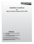
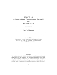
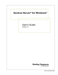
Installation and Operating Instructions
GENERATOR SAFETY TRANSFER SWITCH MODELS 2026, 3028
Thank you for purchasing a GenTran® Manual Transfer Switch designed to
safely connect a portable generator to the load center in your home or
business (single phase only) for standby power applications. Product features
include:
•
•
•
•
•
•
•
Generator and Utility feeds mechanically interlocked to prevent dangerous
utility or generator back feeding – thereby avoiding property damage and
serious injury to electrical workers.
Pre wired for fast, easy connection to the load center
Each model can be expanded to up to 10 circuits using interchangeable type
circuit breakers – so as your needs change, just expand it!
Accommodates GFCI and Arc-Fault breakers to meet the latest NEC
requirements.
Dual wattmeters are provided to help you monitor and balance the loads on
your generator, prolonging generator life
Flexible generator connections – Use the Power Inlet for a quick cord
connection to your generator, or ask your contractor to hardwire your
generator connection.
Surface or Flush Mounting (with flush mounting plate sold separately).
Warning: Gen/Tran transfer switches should be installed by a professional electrician familiar with electrical wiring and codes, and
experienced in working with generators. Gen/Tran accepts no responsibility for accidents, damages or personal injury caused by
incorrect installation. These transfer switches are intended for surface mounting INDOORS only. GenTran transfer switches are UL
listed to UL Standard 1008 and meet the criteria of National Electrical code Article 702.6 for Optional Standby Systems.
Caution: If using the generator and transfer switch for larger appliances, such as electric water heaters, clothes dryers, electric ranges
and small air conditioners, check the labels on the appliances to be sure they do NOT exceed the rating of the generator. No
appliance should have an amperage rating that exceeds the individual breaker rating in the transfer switch (20 or 30 amps).
Model:
# Circuits Provided
Max # Circuits
REQUIRED BREAKER FOR MAIN LOAD CENTER
(not included in this kit)
Breakers Provided with Unit
Max GEN Watts
Max GEN Amps
Voltage
NEMA Type Enclosure
NEMA Configuration of Male Inlet
Phase
Minimum Gauge Cord Size
2026
6
10
60 amp 2-pole
3028
8
10
60 amp 2-pole
2 – 15 amp 1-pole
2 – 20 amp 1-pole
1 – 20 amp 2-pole
2 – 15 amp 1-pole
2 – 20 amp 1-pole
1 – 20 amp 2-pole
1 – 30 amp 2-pole
7500
30 Amps
120/240 Volts
1 – Indoor Only
L14-30
1
10/4
5000
20 Amps
120/240 Volts
1 – Indoor Only
L14-20
1
12/4
Tools Needed for Installation:
•
•
•
•
Power Drill
Wire Stripper and cutter
Screw drivers
Tape measure
•
•
•
Wall anchors and screws
Other supplies needed if hardwiring to a Power Inlet
Box include Romex, ½” connector, and wire connectors
2-pole 60 amp breaker for main panel
Planning Your Transfer Switch Installation:
1. Determine the appliances, circuits or equipment you want to operate with generator power during a power outage, such as:
• Refrigerator/Freezer
• Water Heater
• Security System
• Furnace Blower (gas/oil only)
• Garage Door Opener
• Sump Pump
• TV / Radio
• Microwave, Coffee Maker
• Computer, Fax and Printer
• Lights
• Well Pump
• Cordless Telephone
2.
3.
4.
Determine the amps required for each appliance by reading the label on the appliance. IMPORTANT: No appliance should have
an amperage rating that exceeds the individual breaker rating in the transfer switch. The total amperage of all circuits can exceed
the generator rating, but not all circuits will be able to be used concurrently. Do not connect a 50-amp circuit (such as central air
conditioning or Electric Range) to this system. GenTran is not responsible for accidents or property damage due to incorrect or
inappropriate installation.
Assign the circuit # in the load center and in the GenTran® transfer switch, matching the size of the circuit breaker in the load
center to the circuit breaker in the transfer switch. Once you’ve determined which circuits you want to connect and the
appropriate amperage, you will be ready to begin installing your GenTran® transfer switch.
The location of your load center/electrical panel in your home or business will determine where the GenTran® transfer switch will
be installed. Refer to the illustrations below. In addition to the transfer switch, you may need additional accessories to complete
your generator transfer switch installation, such as a generator cord and power inlet box. A generator cord (sold separately) is
needed to connect your generator to the GenTran® transfer switch or power inlet box. If your load center is in your garage, we
recommend at least a 25-foot generator cord to reach from your generator outside the garage on the driveway to the transfer
switch. NEVER run a generator in an enclosed area! If your load center is in a basement or interior room, you shall install a
power inlet box (sold separately) on the exterior of your house or building to avoid running the generator cord through a door or
window. Once you have all of the essential components for your specific needs, you may proceed with the installation.
HARDWIRED/BASEMENT INSTALLATION:
TYPICAL GARAGE INSTALLATION:
Power Inlet Box
25 ft. Power Cord
Installation Procedure:
IMPORTANT: Please read this entire procedure before beginning installation. WARNING: For SAFETY, turn OFF
the MAIN circuit breaker in the load center BEFORE starting installation. Remember, the wiring ahead of the
MAIN is HOT, even when the main circuit breaker is off.
Installations with a Generator Cord Connection (Garage Installations):
1.
2.
3.
4.
Select a location on right or left side of load center approximately 12 inches to the side of the load center.
Find a knockout (KO) on the lower side of the load center that matches the conduit fitting size provided with the Transfer Switch
(1” on both models).
Remove the cover from the load center and the knockout selected in step 2.
Determine if the conduit length provided needs to be shortened. If so, remove the wires from the conduit before cutting to avoid
damaging the wires. Then use a utility knife to cut conduit to desired length. . [NOTE: The Electrical Non-Metallic Tubing (ENT)
2
is UL Listed and recognized by the National Electrical Code (NEC). However, it generally cannot be used in buildings that exceed
(3) floors above grade. While the NEC does allow its use for this application, local codes and inspectors may prohibit its use in
your area. If this situation exists, call 888-GEN-TRAN to request a length of flexible metal conduit (FMC) to use in its place.]
5.
6.
Assemble the conduit to the load center and transfer switch after putting the wire harness through the selected knockout in the
load center.
Without stressing the flexible conduit, turn the transfer switch to a vertical position, use the enclosed template to mark the hole
locations, and anchor the unit to the wall.
Hardwired Installations from a Power Inlet Box to the Transfer Switch (Basement Installations):
1.
2.
3.
4.
5.
6.
7.
Follow steps 1 thru 6 above.
To remove the male inlet from lower front of transfer switch, remove the three (3) screws that secure it to the frame. Pull it
directly out. Then loosen the screws that secure the wires into the flanged inlet. Remove and set aside the four (4) screws (2 on
the top, 2 on the bottom) securing the cover. Pull off the cover.
Five (5) ½” knockouts are provided for easy wiring using Romex or conduit. Locate and remove your desired knockout. Then
insert connector and locknut followed by the wires.
Feed sufficient wire into the transfer switch so that it can be pulled 4” through the removed inlet hole.
Connect the wires you just fed through to the four wires removed from the male inlet using wire connectors (provided by
installer). Connect black to black, red to red, and so on.
Push wires and wirenuts back into the cavity in the lower portion of the transfer switch. Use the closing plate provided in the
hardware kit to cover the hole left by removing the male inlet.
Neatly route the Romex out to the Power Inlet Box. Be sure to secure it according to code along the way.
®
Wiring your GenTran Transfer Switch to the Load Center:
1.
2.
3.
9.
Please note on the transfer switch that each circuit breaker is rated at 15 amps, 20 amps or 30 amps (on model 3028 only).
Installer MUST select the same breaker size in the load center for each circuit in the transfer switch (ie: 15 amps only with 15
amps, 20 amps only with 20 amps, etc.).
It is recommended that the MAIN circuit breaker in the Load Center be turned OFF while connecting the wires from the transfer
switch to those in the Load Center. Remember that the wires ahead of the MAIN BREAKER are still HOT, and could cause serious
injury or death if not handled properly. Use extreme CAUTION when wiring inside a LIVE load center.
4. From the harness wires now in the load
center, locate wire A4. Then select a
desired circuit breaker in the load center
Model 3028
with the same rating (ex: 15 amps). See
Wiring Diagram at left.
5. Turn off this selected breaker and remove
the wire from the breaker in the LC.
Connect Blue wire using a wirenut to the
wire removed from the breaker.
6. Locate the blue wires with the
corresponding markings (ie: A5, B5, A6, B6,
etc.) turn OFF the appropriate breaker(s) in
the Load Center, remove the wire(s) from
the breaker(s) cut to a convenient length,
strip each 5/8”, and connect them to the
desired wire from the transfer switch using
wire connectors.
7. Follow this procedure for each of the
remaining circuits. (Blue connected using
wirenuts to the wire removed from the
breaker).
8. Find the White wire from the transfer
switch. Strip 5/8”, and insert into an
unused hole in the Neutral bar.
Find the Green wire from the transfer switch. Strip 5/8”, and insert into the ground bar in the Load Center or if there is no ground
bar, insert it into an unused hole in the neutral bar.
3
10. Install 2-pole 60 amp breaker (provided by installer) into two unused spaces in load center. If all spaces are full, remove two
adjacent 1-pole or one 2-pole breaker that will be abandoned and relocated in the transfer switch. After inserting the 2-pole 60
amp breaker, strip 5/8” and insert black #6 wires from transfer switch.
11. Replace cover on load center, and reinstall cover to transfer switch if applicable. Installation is complete.
Adding Circuits to your GenTran® Transfer Switch:
This GenTran™ transfer switch can be expanded in the field to 10 circuits. The 1” (full size) branch circuit breakers in this transfer
switch can be removed and replaced with ½” (twins or half size) breakers from Siemens, Type QE, QP, QT, QPF, QPH, HQP, QPHF,
QAF; Square D, type HOM; GE, type THQL; Cutler-Hammer, type BR, max. 30 Amps, 240 VAC, min. 10 kA, 240 VAC short circuit rating.
Appropriate wire and wire connectors shall be provided by installer. Follow procedure in Step 7 under “Wiring Your GenTran Transfer
Switch” above for connection of the additional circuits.
Using your GenTran® Transfer Switch:
Transferring from Utility Power to Generator Power:
1.
2.
3.
4.
5.
6.
7.
8.
Move generator outdoors. WARNING: Operating a generator indoors or in an enclosed area could result in injury or death.
Insert the male connector of the Power Cord into the correct outlet on the generator.
Plug in the female connector of the Power Cord to the Power Inlet Box OR the inlet on the front of the transfer switch. Turn all
circuit breakers in the transfer switch to their OFF position.
Start the generator outdoors, following the procedures described in the generator’s owner’s manual furnished by the
manufacturer.
Turn on the GENERATOR MAIN circuit breaker in the transfer switch. Turn ON circuit breakers in the manual transfer switch one
at a time alternating from phase “A” and phase “B.”
Use the wattmeters to test and determine wattage from that shown on each appliance. Make a note of any excessive loads
which must be removed from a given circuit during generator operation in an emergency.
Balance loads. When all loads are on, the difference between the meter readings should not exceed 750 watts. Balancing the
loads properly will extend the life of your generator. If all of the breakers in the transfer switch are ON but the meters are reading
vastly different wattages, it may be necessary for your installer to reopen the load center and switch some loads from “A” to “B”
or vice versa to balance the loads. (Remember, each meter is ½ of the total rating -- A 5000-watt continuous rating generator
will have two 2500-watt meters, and each meter should not exceed the maximum wattage on a continuous basis. If you are
starting up a motor such as on a well pump or power tool, the needle on the meter may move to the maximum rating, but then
should immediately back off to the continuous running current of the load.)
If all circuit breakers on the transfer switch are turned ON without overloading the generator or the meters, then all breakers can
remain in the ON position. If not, you may need to turn off some circuit breakers on the transfer switch to allow some higher
wattage appliances to operate.
Transferring from Generator Power to Utility Power:
1.
2.
3.
4.
5.
6.
On the transfer switch, turn Generator MAIN breaker OFF and turn Utility MAIN breaker ON.
Turn ON any individual circuit breakers in the transfer switch that were OFF.
Shut down the generator, following the procedures in the generator Owner’s Manual.
Unplug the power cord from the generator and then the power inlet.
Cool off the generator and store in a dry, secured location.
To ensure that your generator will work properly when you need it, it is important to start and run your generator under load
regularly and keep the tank filled with fresh fuel. Perform the above steps at least ONCE A MONTH to keep the generator
properly “exercised.” It is not necessary to turn off any circuits in the MAIN load center when supplying generator power to the
transfer switch.
© 2005 Gen-Tran Corporation. All Rights Reserved. GenTran and PowerStay are registered trademarks of Gen-Tran Corporation.
4
Gen/Tran Corporation
Toll Free: 1-888-GEN-TRAN
Fax: 770-552-7756
www.gen-tran.com
PN 500500 Rev D
Instrucciones de Instalación y Operación
INTERRUPTOR DE TRANSFERENCIA DE SEGURIDAD MODELOS 2026, 3028 DE GENERADOR
Gracias por adquirir un interruptor de transferencia Manual GenTran® diseñado para conectar con seguridad un generador portátil al
centro de carga en su casa o negocio (solo de fase sencilla) para aplicaciones de electricidad de reserva. Las características del producto
incluyen:
♦ Alimentadores de generador y servicio público entrelazados mecánicamente para evitar la peligrosa alimentación regresiva del
servicio público o el generador – evitando así el daño a la propiedad y lesión seria a los trabajadores de la electricidad.
♦ Previamente cableado para una conexión rápida y fácil al centro de carga
♦ Cada modelo puede expandirse a un máximo de 10 circuitos usando disyuntores de circuitos del tipo intercambiable – de manera
que en la medida en que sus necesidades cambian, ¡usted sólo las expande!
♦ Es apto para los interruptores automáticos GFCI y Arc-Fault para cumplir con los más recientes requisitos de Código Eléctrico
Nacional (NEC)
♦ Se suministran medidores dobles de vatios para ayudarle a usted a monitorear y equilibrar las cargas en su generador,
prolongando así la vida útil de su generador
♦ Conexiones flexibles del generador – Use la Entrada de Poder para una conexión rápida de cable a su generador, o pídale al
contratista que hardware la conexión de su generador.
Advertencia: Los interruptores de transferencia Gen/Tran deben ser instalados por un electricista profesional familiarizado con el cableado y los
códigos eléctricos, y con experiencia de trabajo con generadores. Gen/Tran no se hace responsable por accidentes, daños o lesión personal causada
por instalaciones incorrectas. Estos interruptores de transferencia son diseñados para ser montados sobre una superficie solamente en INTERIORES.
Los interruptores de transferencia GenTran están listados por UL (Underwriting Laboratories) al Estándar 1008 de UL y cumplen con los criterios del
Artículo 702.6 del Código Eléctrico Nacional para los Sistemas Opcionales de Reserva.
Precaución: Si se está usando el generador y el interruptor de transferencia para electrodomésticos grandes, tales como calentadores eléctricos de
agua, secadoras de ropa, estufas eléctricas y aires acondicionados pequeños, revise las etiquetas de los electrodomésticos para asegurarse que los
mismos NO exceden las condiciones normales de funcionamiento del generador. Ningún electrodoméstico debe tener una clasificación de amperaje
que exceda la tasa del disyuntor eléctrico individual del interruptor de transferencia (20 ó 30 amperios).
Modelo:
Número de circuitos suministrados
Máximo número de circuitos
INTERRUPTOR REQUERIDO PARA EL CENTRO DE
CARGA PRINCIPAL (no se incluye en este paquete)
Interruptores suministrados con la unidad
Máximo número de vatios GEN
Máximo número de amperios GEN
Voltaje
Recinto de tipo NEMA
Configuración NEMA de entrada macho
Fase
2026
3028
6
10
60 amperios 2-polos
8
10
60 amperios 2-polos
2 – 15 amperios 1-polo
2 – 20 amperios 1-polo
1 – 20 amperios 2-polos
2 – 15 amperios 1-polo
2 – 20 amperios 1-polo
1 – 20 amperios 2- polos
1 – 30 amperios 2- polos
7500
30 amperios
120/240 voltios
1 – Interiores solamente
L14-30
1
5000
20 amperios
120/240 voltios
1 – Interiores solamente
L14-20
1
Herramientas necesarias para la instalación:
•
•
•
•
•
Taladro eléctrico
Pelador y cortador de cable
Destornilladores
Cinta de medir
Sujetadores de pared y tornillos
•
•
Otros suministros necesarios si se está conectando
directamente a una caja de entrada de electricidad incluyen
Romex, conector de ½ pulgada y conectores de cable
Interruptor 60 amperios 2-polos para el centro de carga
principal
Planificando la instalación del interruptor de transferencia:
1. Determine los electrodomésticos, circuitos o equipo que usted desea operar con energía del generador durante una interrupción de la energía,
tales como:
• Refrigerador / congelador
•
Calentador de agua
•
Sistema de seguridad
• Soplador de horno (sólo gas / aceite)
•
Abridor de puerta de garaje
•
Bomba de sumidero
• Televisor / radio
•
Microondas, máquina cafetera
•
Computadora, fax e impresora
• Luces
•
Bomba de pozo
•
Teléfono inalámbrico
5
2.
3.
4.
Determine los amperios requeridos para cada electrodoméstico leyendo la etiqueta del electrodoméstico. IMPORTANTE: Ningún
electrodoméstico debe tener una tasa de amperaje que exceda la tasa individual de disyuntor del interruptor de transferencia. El
amperaje total de todos los circuitos puede exceder la tasa del generador, pero no todos los circuitos podrán ser usados
concurrentemente. No conecte un circuito de 50 amperios (como un aire acondicionado central o una estufa eléctrica) a este
sistema. GenTran no se hace responsable por accidentes o daño a la propiedad debidos a una instalación incorrecta o
inapropiada.
Asigne el número de circuito en el centro de carga y en el interruptor de transferencia GenTran®, haciendo coincidir el tamaño del
disyuntor de circuito en el centro de carga al disyuntor de circuito en el interruptor de transferencia. Una vez que usted ha
determinado cuáles circuitos desea conectar y el amperaje apropiado, estará listo para comenzar a instalar su interruptor de
transferencia GenTran.
La ubicación del centro de carga / panel eléctrico en su casa o negocio determinará dónde se instalará el interruptor de
transferencia GenTran®. Refiérase a las ilustraciones de abajo. Además del interruptor de transferencia, usted podría necesitar
accesorios adicionales para completar la instalación del interruptor de transferencia para su generador, como por ejemplo un
cable de generador y una caja de entrada eléctrica. Un cable de generador (vendido separadamente) es necesario para conectar
su generador al interruptor de transferencia GenTran® o caja de entrada eléctrica. Si su centro de carga está en su garaje,
nosotros recomendamos un cable de generador de por lo menos 25 pies para alcanzar desde su generador saliendo del garaje por
la entrada de coches hasta el interruptor de transferencia. ¡NUNCA haga funcionar un generador en un área cerrada! Si su centro
de carga está en un sótano o en un cuarto interior, usted debe instalar una caja de entrada eléctrica (vendida separadamente) en
un área exterior de su casa o edificio para evitar correr el cable del generador a través de una puerta o ventana. Una vez que
usted tiene todos los componentes esenciales para sus necesidades específicas, puede proceder con la instalación.
INSTALACIÓN DIRECTA / EN UN SÓTANO:
INSTALACIÓN TÍPICA EN UN GARAJE:
Caja de entrada
de electricidad
Cable de electricidad
de 25 o mas pies
Procedimiento de instalación:
IMPORTANTE: Por favor lea este procedimiento en su totalidad antes de comenzar la instalación. ADVERTENCIA:
Para SEGURIDAD, coloque en posición de APAGADO el disyuntor de circuito PRINCIPAL en el centro de carga
ANTES de comenzar la instalación. Recuerde, el cableado anterior al PRINCIPAL está ELECTRIFICADO, aun cuando
el disyuntor de circuito principal está apagado.
Instalaciones con una conexión de cable de generador (Instalaciones de garaje):
1.
2.
3.
4.
5.
Seleccione una ubicación al lado derecho o izquierdo del centro de carga, aproximadamente a 12 pulgadas al lado del centro de
carga.
Encuentre un orificio de abrir en la parte baja del centro de carga que coincida con el tamaño del enchufe del conducto
suministrado con el interruptor de transferencia (1 pulgada en ambos modelos).
Retire la cubierta del centro de carga y del orificio seleccionado en el paso 2.
Determine si la longitud del conducto suministrado necesita acortarse. De ser así, retire los cables del conducto antes de cortar
para evitar el dañar los cables. Entonces use una navaja utilitaria para cortar el conducto a la longitud deseada.
[NOTA: El entubado no metálico eléctrico (ENT) está listado con UL y es reconocido por el Código Eléctrico Nacional (NEC). Sin
embargo, el mismo generalmente no puede ser usado en edificaciones que superan tres (3) pisos por encima del declive. Si bien el
NEC no permite su uso para esta aplicación, los códigos e inspectores locales podrían prohibir su uso en su área. Si este fuera el
caso, llame al 888-GEN-TRAN para solicitar una medida de conducto metálico flexible (FMC) para usarlo en su lugar.]
6
6.
7.
Ensamble el conducto al centro de carga y al interruptor de transferencia después de colocar la montura del cable a través del orificio
seleccionado en el centro de carga.
Sin estirar el conducto flexible, voltee el interruptor de transferencia a una posición vertical, use el templete adjunto para marcar las
ubicaciones de los orificios, y ancle la unidad a la pared.
Instalaciones directas desde una caja de entrada eléctrica al interruptor de transferencia (Instalaciones en sótanos):
1. Siga los pasos del 1 al 6 de arriba.
2. Para retirar la entrada macho del frente inferior del interruptor de transferencia, retire los tres (3) tornillos que lo aseguran del marco.
Hálelo directamente hacia afuera. Entonces afloje los tornillos que aseguran los cables hacia la entrada con reborde. Retire y coloque
a un lado los cuatro (4) tornillos (2 en la parte superior, 2 en la parte inferior) asegurando la cubierta. Saque la cubierta.
3. Se suministran cinco (5) orificios de abrir de ½ pulgada para un cableado fácil usando Romex o conducto. Localice y retire el orificio
de abrir deseado. Luego inserte el conector y la tuerca seguida de los cables.
4. Alimente suficiente cable dentro del interruptor de transferencia para que el mismo pueda ser halado 4 pulgadas a través del orificio
de entrada que ha sido retirado.
5. Conecte los cables que recién alimentó a través de los cuatro cables retirados de la entrada macho usando conectores de cable
(suministrado por el instalador). Conecte negro a negro, rojo a rojo, y así sucesivamente.
6. Presione los cables y sus soportes dentro de la cavidad en la porción inferior del interruptor de transferencia. Use la placa de cierre
suministrada en el estuche de ferretería para cubrir el orificio que queda, retirando la entrada macho.
7. Encamine de manera organizada el Romex hacia la caja de entrada eléctrica. Asegúrese de fijarlo a lo largo de acuerdo con el código.
Instalando el cableado del interruptor de transferencia
GenTran® al centro de carga:
1.
2.
6.
7.
8.
9.
Por favor note en el interruptor de transferencia que cada disyuntor de circuito está tasado a 15 amperios, 20 amperios ó 30 amperios
(en el modelo 3028 solamente).
El instalador DEBE seleccionar el mismo tamaño de disyuntor en el centro de carga para cada circuito en el interruptor de
transferencia (por ejemplo: 15 amperios sólo con 15
Modelo 3028
amperios, 20 amperios sólo con 20 amperios, etc.).
3. Se recomienda que el disyuntor de circuito
PRINCIPAL en el centro de carga se ajuste a
APAGADO mientras se conectan los cables desde el
interruptor de transferencia hacia aquellos en el
centro de carga. Recuerde que los cables que
anteceden al INTERRUPTOR PRINCIPAL aun están
ELECTRIFICADOS, y podrían causar lesión seria o la
muerte si no se manejan apropiadamente. Use
PRECAUCIÓN extrema cuando esté instalando
cableado dentro de un centro de carga
ELECTRIFICADO.
4. A partir de los cables montados ahora en el centro
de carga, localice el cable A4. Luego seleccione un
selector deseado en el disyuntor de circuito en el
centro de carga con la misma tasa (por ejemplo: 15
amperios). Vea el Diagrama de Cableado a la
izquierda.
5. Apague este interruptor seleccionado y retire el
cable del interruptor en el LC. Conecte el cable Azul
al cable retirado del interruptor usando una tuerca
de cable.
Localice los cables azules con las marcas correspondientes (por ejemplo: A5, B5, A6, B6, etc.) ajuste a APAGADO el (los) disyuntor
(es) apropiado(s) en el centro de carga, retire el (los) cable(s) del (de los) disyuntor (es) corte a una longitud conveniente, pele cada
uno 5/8 de pulgada, y conéctelos al cable deseado del interruptor de transferencia usando conectores de cable.
Siga este procedimiento para cada uno de los circuitos restantes. (Azul conectado usando tuercas de cable al cable retirado del
disyuntor).
Encuentre el cable Blanco del interruptor de transferencia. Pele 5/8 de pulgada e insértelo dentro de un orificio no utilizado en la
barra neutra.
Encuentre el cable Verde del interruptor de transferencia. Pele 5/8 de pulgada e insértelo dentro de la barra de tierra en el centro de
carga o, si no hubiese barra de tierra, insértelo dentro de un orificio no utilizado en la barra neutra.
7
10. Reemplace la cubierta en el centro de carga y reinstale la cubierta del interruptor de transferencia si se aplica. La instalación ha sido
completada.
Agregando circuitos al interruptor de transferencia GenTran®:
Este interruptor de transferencia GenTran™ puede expandirse en el campo a 10 circuitos. Los disyuntores de circuitos bifurcados de 1
pulgada (tamaño completo) en este interruptor de transferencia pueden ser retirados y reemplazados con interruptores de ½ pulgada
(gemelos o de tamaño mediano) de Siemens, Tipo QE, QP, QT, QPF, QPH, HQP, QPHF, QAF; Square D, tipo HOM; GE, tipo THQL; CutlerHammer, tipo BR, de un máximo de 30 Amperios, 240 VAC, un mínimo de 10 kA, 240 VAC de tasa de corto circuito. El instalador debe
proveer cables y conectores de cable apropiados. Siga el procedimiento en el Paso 7 bajo “Instalando el cableado del interruptor de
transferencia GenTran” que aparece anteriormente para la conexión de los circuitos adicionales.
Usando el interruptor de transferencia GenTran®:
Transfiriendo electricidad de servicio público a electricidad de generador:
1.
2.
3.
4.
5.
6.
7.
8.
Mueva el generador a exteriores. ADVERTENCIA: Operar un generador en interiores o en un área cerrada podría resultar en
lesión o muerte.
Inserte el conector macho del cable de electricidad dentro de la toma correcta del generador.
Enchufe el conector hembra del cable de electricidad a la caja de entrada eléctrica O a la entrada frontal del interruptor de
transferencia. Ajuste todos los disyuntores de circuito del interruptor de transferencia a su posición de APAGADO.
Encienda el generador en exteriores, siguiendo los procedimientos descritos en el manual del propietario del generador provisto por
el fabricante.
Encienda el disyuntor de circuito PRINCIPAL del GENERADOR en el interruptor de transferencia. Ajuste los disyuntores de circuito a
ENCENDIDO en el interruptor de transferencia manual, uno por uno, alternando entre la fase “A” y la fase “B”.
Use los medidores de potencia en vatios para probar y determinar la potencia en vatios de acuerdo a partir de la que muestra cada
electrodoméstico. Tome nota de cualquier carga excesiva que deba ser retirada de un circuito determinado durante la operación del
generador en una emergencia.
Equilibre las cargas. Cuando todas las cargas están encendidas, la diferencia entre las lecturas de medidor no deben exceder 750
vatios. Equilibrar las cargas apropiadamente extenderá la vida de su generador. Si todos los disyuntores del interruptor de
transferencia están ENCENDIDOS, pero los medidores están leyendo potencias en vatios demasiado diferentes, podría ser necesario
que el instalador vuelva a abrir el centro de carga y cambie algunas cargas de “A” a “B” o viceversa para equilibrar las cargas.
(Recuerde, cada medidor es ½ de la tasa total – Un generador de tasa continua de 5.000 vatios tendrá dos medidores de 2.500
vatios, y cada medidor no debe exceder la máxima potencia en vatios de manera continua. Si usted está encendiendo un motor como
por ejemplo el de una bomba de pozo o de una herramienta eléctrica, la aguja del medidor podría moverse hacia la tasa máxima,
pero enseguida debe devolverse hacia la corriente de funcionamiento continuo de la carga.)
Si todos los disyuntores de circuitos del interruptor de transferencia se ajustan a ENCENDIDO sin sobrecargar el generador o los
medidores, entonces todos los interruptores pueden permanecer en la posición de ENCENDIDO. Si no, usted podría tener que apagar
algún disyuntor de circuitos en el interruptor de transferencia para permitir que algunos electrodomésticos de mayor potencia en
vatios puedan operar.
Transfiriendo de electricidad de generador a electricidad de servicio público:
1.
2.
3.
4.
5.
6.
En el interruptor de transferencia, ajuste el interruptor PRINCIPAL del generador a APAGADO y ajuste el interruptor PRINCIPAL de
servicio público a ENCENDIDO.
Ajuste a ENCENDIDO cualquier disyuntor de circuitos individual en el interruptor de transferencia que estuviera APAGADO.
Apague el generador, siguiendo los procedimientos indicados en el manual del propietario del generador.
Desconecte el cable eléctrico del generador y luego la entrada de electricidad.
Deje enfriar el generador y almacénelo en un lugar seco y asegurado.
Para asegurarse que su generador funcionará apropiadamente cuando lo necesite, es importante encender y hacerlo funcionar bajo
carga regularmente y mantener el tanque con combustible fresco. Lleve a cabo los pasos anteriores por lo menos UNA VEZ AL MES
para mantener el generador apropiadamente “ejercitado”. No es necesario apagar circuito alguno en el centro de carga PRINCIPAL
cuando se le esté suministrando electricidad de generador al interruptor de transferencia.
© 2005 Gen-Tran Corporation. Todos los derechos están reservados. GenTran y PowerStay son marcas comerciales de Gen-Tran Corporation.
8
Gen/Tran Corporation
Sin cargo: 1-888-GEN-TRAN
Fax: 770-552-7756
www.gen-tran.com
PN 500500 Rev D