1
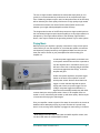
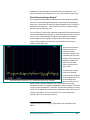
654 S Lucile St
Seattle, WA 98108
Tel: (206) 762 8383
Fax: (206) 762 8389
Owners Manual
Genesis Reference-Series Amplifier
Version 2.0
September 2008
Copyright Genesis Advanced Technologies
All Rights Reserved
absolute fidelity®
OWNERS MANUAL
Genesis Reference Amplifier
Contents
Set-up and Safety Information ........................................................................ 3
Unpacking and Setting Up .......................................................................... 3
Safety Information ....................................................................................... 4
Set-up and Operation ..................................................................................... 6
Speaker Connections.................................................................................. 6
Input Connections ....................................................................................... 6
Playing Music .............................................................................................. 7
About Your Amplifier....................................................................................... 9
Introduction.................................................................................................. 9
Design and Construction............................................................................. 9
Dynamic Power Delivery Supply (DPDS)................................................ 9
Silent Running Voltage Supply.............................................................. 11
Resonance and Vibration Control ......................................................... 12
Acoustic Suspension System ................................................................ 13
Specifications (Each) .................................................................................... 14
A Message from Genesis
The transparency, detail retrieval, macro- and micro-dynamics, and
wide frequency extension of Genesis loudspeakers place great
demands on the quality of amplification. Hence, to match the Genesis
loudspeakers, the Genesis Reference Series of amplifiers was
created as the finest musical amplifiers available.
Please write the serial number and
purchase details of your Genesis
Reference Amplifier here for future
reference.
Serial Nos.: __________________
Bought at: ___________________
____________________________
Date: _______________________
Address: ____________________
The Genesis Reference Amplifier, together with a pair of Genesis
loudspeakers, will give your entire music collection a whole new life.
In a well set-up system, it is capable of transporting the musical
performance into your room. The hiss and hum normally associated
with vacuum tubes are completely absent, while retaining the
richness and rightness of the best of this genre of amplifiers.
Transistor etch and harshness are completely absent, while retaining
the slam and control of the best of solid-state.
During development, we benchmarked against the best cost-noobject amplifiers – both solid-state and vacuum tube. While we were
intent on developing a value-priced product, quality has not been
scaled down. Hand-selected, precisely matched components are
used throughout: copper-core silver wire with Teflon insulation is used
in the entire signal and power path. Each and every unit is completely
hand-assembled in the USA, and burned-in before final testing and
measurement.
The result of all this obsessive attention to detail is a fabulously
musical power amplifier capable of driving almost any loudspeaker in
the world. The state of the environment is also taken care of with
extremely high efficiency, instant warm up, and a simple, functional,
and elegant design.1
_________________________
Tel:
________________________
Before using this unit, please take the time to carefully review the
safety instructions and operating information contained in this
Owner’s Manual. Becoming familiar with your new amplifier and the
correct operating procedures will help assure you of safe usage,
reliable operation, and maximum musical enjoyment.
1
Some of the inspiration for the GR-Amp came from the sci-fi movies “Silent
Running” and “Max Headroom: 20 Minutes into the Future”.
Genesis Reference Amplifier Owners Manual Ver 2.0
2
Set-up and Safety Information
Now that you have your new amplifier, we realize that you can't wait to hook
it up and start playing! However, please read this set-up guide and safety
information before you proceed.
Unpacking and Setting Up
The amplifier is likely to come in parts – the amplifier module, an acoustic
suspension, and a power transformer (an auxiliary power supply upgrade
called the Maximum Dynamic Headroom Reservoir is also available) unless
your dealer has assembled it for you. So, some assembly may be needed
before you can start playing. It is important that this product is never used
near water or sources of water. Avoid bathrooms, washbowls, kitchen sinks,
swimming pools, etc.
Carefully remove the various parts of the amplifier package from the cartons
and unwrap it. The suspension system will need to be assembled to the
amplifier chassis. You will use the hex key and four hex screws supplied to
do this.
Place the amplifier chassis top down on a clean surface.
Place the suspension frame on the shock absorbers so that
the holes of the shock absorbers are aligned with the
matching holes on the frame. The suspension frame “points”
forwards so that the tip of the triangle faces to the front of
the amplifier, and the round hole is in the front.
Use the hex screws and the supplied hex key to secure the
suspension frame to the shock absorbers. Do not overtighten the screws.
Turn the amplifier over, screw in the steel spike bolts into
the threaded holes in each corner of the suspension frame.
Screw them in so that the spikes protrude by about a third of
an inch (8mm) from the bottom of the frame and no more.
The Acoustic Suspension will allow the amplifier to be
placed directly on the floor, or on any piece of furniture or
equipment rack. The amplifier should not be subject to
vibration of any sort. Do not place them directly in front of, or
on top of your loudspeakers. Despite the vibration and
resonance control measures already taken in the Genesis
Reference Amplifier, we are not able to completely eliminate
all incoming vibration.
Genesis Reference Amplifier Owners Manual Ver 2.0
3
Once you decide on the placement of the amplifier module, and connect the
power transformer using the supplied Power Umbilical, locate the power
transformer module as far away from the listener as possible. The Power
Umbilical will only go in one way so the assembly should be obvious. Align
the plugs to the like-colored sockets, insert and twist until the lock “clicks”.
If you have the optional Maximum Dynamic Headroom Reservoir (MDHR),
2
place that on top of the amplifier module , and connect the two using the
short Power Umbilical supplied with the MDHR. Then, connect the power
transformer module to the MDHR.
Before you plug the power cord in the power transformer, please make
sure that you have the power transformer with the proper voltage for
the country you are in. Taiwan, Japan and North America will require the
115V version. Most European countries and other Asian countries will
require the 230V version. Also, make sure that you have the appropriate
power transformer for the amplifier model that you have.
Connect the loudspeakers to the 5-way binding posts using good quality
loudspeaker cables, and the appropriate RCA or XLR interconnects to the
pre-amplifier.
Safety Information
1.
Never try to disassemble the amplifier as you may be exposed
to dangerous voltages. Even after turning the amplifier off and
unplugging it from the wall socket, it will retain a lethal electrical
charge for a very long time. There is huge energy storage in the
power supply capacitors (and even more so in the MDHR!!).
2.
Do not attempt to modify the amplifier. The device has been
tested and adjusted for optimal operation and should give you
years of trouble-free service.
3.
Do not connect/disconnect the power supply and power
transformer from the amplifier module without turning the
amplifier off first.
2
Note that the rubber feet of the MDHR may mark the top of the amplifier
module, but this is easily cleaned off using rubbing alcohol or “Goof Off”.
However, please note that the placement and material of the rubber feet will
serve to further damp the top plate of the amplifier module. Do not be
tempted to use cones or other forms of isolation between the MDHR and the
amplifier module. The top of the amplifier chassis holds the signal path.
Genesis Reference Amplifier Owners Manual Ver 2.0
4
4.
Before turning the amplifier on, both inputs and outputs should
be properly connected. Do not run the amplifier without the
appropriate loudspeakers connected to it.
5.
While the Genesis Reference Amplifier runs very cool due to its
high efficiency, some ventilation and airflow at the faceplate is
necessary for reliable operation. Do not obstruct the vents at the
sides of the chassis, or the holes on the bottom cover.
6.
Do not connect or disconnect the loudspeakers from the
amplifier while it is playing. Turn the amplifier off, and wait a few
seconds before making any connections.
Genesis Reference Amplifier Owners Manual Ver 2.0
5
Set-up and Operation
Speaker Connections
A pair of 5-way insulated binding posts is provided on the rear of your
amplifier. While this allows bare wire to be used, we recommend that firstly
banana plugs, or secondly spade lugs be used instead of bare wire. Make
sure that your speaker cables are firmly connected to the correct speaker
connections.
The binding posts are ETI CablePods™ for
improved signal transfer, enhanced sonic
performance, and a faster, more direct
connection. The positive (signal) terminal is
identified by the red ring on the base; and
the negative (return) terminal is identified by
the black ring on the base.
If you are using banana plugs, you may have
to remove the little plastic covers (if installed)
on the top of each CablePod™. If you are using spade lugs, unscrew the
binding posts, insert the spades, and hand tighten. Do not use pliers or other
tools to tighten the binding posts as you may strip the plastic threads on the
posts. These ETI CablePods are designed to fully tighten without the use of
tools.
DO NOT SHORT THE TERMINALS
TOGETHER AND DO NOT GROUND THE
LOUDSPEAKER TERMINALS
Unlike many other Class D amplifiers, the output terminals of the GR-Amp
do not “float” at a significant voltage above ground potential – which makes
the GR-Amp useable with all loudspeakers, including those with built-in
powered subwoofers and electrostatic designs. However, this does NOT
mean that you can ground the negative terminal of the speaker outputs. Do
NOT even attempt to short the two negative (return) terminals together. The
amplifier CAN NOT be bridged for higher power.
Input Connections
Use a pair of high-quality interconnects to hook up the output of your
preamplifier to the input of the GR-Amp. The balanced-input GR-Amp is a
fully balanced, differential amplifier, and hence, a true-balanced source is
crucial for top performance. The balanced input of the GR-Amp uses the
standard configuration for the XLR input of pin 2 “hot”. Pin 1 is signal ground,
and pin 3 is the signal “return”.
Genesis Reference Amplifier Owners Manual Ver 2.0
6
The use of single-ended to balanced converters that simply short pin 3 to
ground is not recommended as performance will be compromised. Some
form of balancing adapter may be used, but the performance of the GR-Amp
will be limited by the sonic quality of the device. A high quality single-ended
to balanced converters such as the FM Acoustics FM214 can be used
between your single-ended preamplifier and the GR-Amp.
The single-ended version of the GR-Amp converts a single-ended input into
the true balanced signal required by the amplifier at a very slight reduction in
transparency. The single-ended version of the GR-Amp is ground-lifted.
Hence, care may be needed in the grounding scheme of your entire system.
Playing Music
Make sure that your amplifier is properly connected to a high-current power
outlet. Before you turn the amplifier on, check that the speaker connections
and inputs are properly hooked up and tightened. Make sure that you turn
down the volume control on your preamplifier first before turning your
amplifier on.
Locate the power toggle switch on the back next
to the power umbilical inlet and flick it upwards to
turn the amplifier ON. In less than a second, you
will hear a faint click to indicate that the soft-start
3
circuit has engaged and the LED(s) under the
amplifier will glow.
Unlike most power amplifiers, the power toggle
switch on the back of the amplifier is not the
actual power switch. We have found that most
toggle or rocker switches degrade the power
supply path. Hence, the power toggle is a lowvoltage, low-power trigger that switches in a
high-current hermetically sealed relay with silver
contacts that is the actual power switch. Hence, if the amplifier does not
switch on or off, resist flicking the switch up and down quickly. Wait a couple
of seconds before trying the switch again.
Give your amplifier a warm-up period of at least 10 seconds for the circuits to
stabilize before attempting to play any music. Because of a special “stay
warm” circuit, as long as the amplifier is plugged in continuously, it will warm
3
Note that there are two blue LEDs under the 360W amplifier module, and
one blue LED under the 180W amplifier module.
Genesis Reference Amplifier Owners Manual Ver 2.0
7
up almost instantly, and be ready to play the moment you turn it on. The
“stay warm” circuits consume about as much power as a night-light.
To turn the amplifier back to stand-by, flick the power toggle up. When you
know that you will not be using the amplifier for a long period of time (for
example when you go on a business trip or a vacation), please unplug the
power transformer at the wall outlet.
Genesis Reference Amplifier Owners Manual Ver 2.0
8
About Your Amplifier
Introduction
The Genesis Reference Amplifier uses proprietary designs and circuits, high
quality components, and state-of-the-art Class D amplifier modules to deliver
sonic performance rivaling amplifiers costing much, much more. The design
brief was to deliver a load-invariant, wide-bandwidth amplifier that would
deliver the musicality, emotion, and tonal colors of a low-powered valve
amplifier with the reliability, power, and control of a high power solid-state
design.
A valve amplifier matched with an appropriate loudspeaker can produce a
sound that we can only call magic. The hard, brittle, and edgy presentation
of many transistor amplifiers is contrasted with the rich, lush and silky sound
of the tube amplifier. Often, valve amplifiers offer much better imaging and
sound stage presentation compared to an equivalently priced solid-state
amplifier. It is more musical, and the performance seems almost alive.
However, a solid-state amplifier often offers better control and dynamics, is
easier to set-up and to own (without having to change tubes every so often).
Except for Class A solid state amplifiers, they also run much cooler and
consume less electricity than valve amplifiers. Solid-state amplifiers are also
able to drive a far wider range of loudspeakers than most valve amplifiers.
The Genesis Reference Amplifier (GR-Amp) offers the best of both worlds.
Design and Construction
The GR-Amp challenges the status quo of music amplifiers by marrying the
advantages of tube (emotion, imaging, soundstage, and portrayal of tonal
colors) with solid state (control, dynamics and accuracy). It uses a modified
Class D power amplifier module with ground-breaking power supply
technologies, and resonance and vibration control to achieve this.
Dynamic Power Delivery Supply (DPDS)
Traditional DC power supplies developed with established design principles
are usually specified into a constant current draw with a resistive load.
However, except for Class A amplifiers (and Class AB at low power), the
load is not linear. The power supply is hence specified for the maximum
current drawn, but such a huge power supply is often slow. Resulting in a
dark, brooding, muscle-bound sound.
The Genesis DPDS, on the other hand, is designed to deliver current into a
non-linear, dynamic musical load, leading to a sense of power with finesse.
The result is that the Genesis Reference Amplifier has the dynamics,
Genesis Reference Amplifier Owners Manual Ver 2.0
9
extension and drive of high-power transistor amplifiers without the musclebound sound, and the elegance, emotion and tonal colors of flea-powered
single-ended triode vacuum tube amplifiers without being weak or flaccid.
The origins of the DPDS comes from the principles of tube amplifier design –
some of the qualities of tube amplifiers were as much to do with power
supply design as the choice of tubes over transistors. Because of the high
voltages involved, tube amplifiers use relatively small capacitors and chokes
to produce smooth DC power.
Transistor amps use cheaper, larger, and lower-voltage electrolytic
capacitors to do much the same job. From this we discover a very simple
fact, smaller capacitors usually sound better. This is not only speculation,
there is good science to predict that the high frequency performance of large
capacitors to be poor.
There are lots of very small solid-state amplifiers that have excellent sound.
They all had tiny power supplies, and the smaller the power supply, the
“faster” they sounded. On the other hand, very large power amplifiers with
huge capacitors, or even large banks of smaller capacitors in their power
supplies tended to sound dark and slow.
The DPDS in the simplest explanation uses the frequency distribution of
music, and the Fletcher Munson curves to predict the required power
delivery to play back music. Then, it uses a Class D amplifier module as a
“perfect music-driven faucet” to deliver current to the connected
loudspeakers.
This is the issue of speed vs power. The sprinter is not able to sustain the
delivery of power for very long, but the marathon runner is not able to deliver
very quick bursts of speed. The DPDS is like a relay team with sprinters,
medium-distance, and long distance runners in the team. Thus, it is able to
deliver high power, as well as very quick bursts of speed.
Such a “relay team” is what gives the Genesis Reference Amplifier the
excellent micro-dynamics, tonal contrasts and timbre textures of lowpowered amplifiers, and yet is able to deliver huge dynamics and the
sustained deep bass of muscle amps.
The optional Maximum Dynamic Headroom Reservoir extends this ability
down to loudspeaker impedances of 1 ohm and below by extending the relay
team, and adds proprietary resonance control circuitry to ensure that the
“baton handover” from one team member to the next is handled as smoothly
as possible. This results in increased dynamics from having more current
Genesis Reference Amplifier Owners Manual Ver 2.0
10
available into lower impedance loads and better micro-dynamics – one
listener described it as “having cream in your coffee instead of non-fat soy”.
Silent Running Voltage Supply4
We recognized that published specifications for noise rejection of opamps
and even discrete small-signal amplification circuits did not always tell the
whole story. The problem is that Power Supply Rejection Ratio, or PSRR, is
specified at one frequency – usually 1kHz, but the truth is that this rapidly
gets worse as the frequency rises.
For the GR-Amp, a low-current regulated voltage supply was developed that
has broad bandwidth noise rejection so that incoming noise does not intrude
on your music. Like the DPDS, the SRVS is also based on the design of
power supplies for tube amplifier design. Because of the high voltages
involved, tube amplifiers use relatively small capacitors and chokes to
produce smooth DC power.
The electronics used for
regulation have to be
noiseless and fast.
Generally noiseless is not
a problem, fast is a great
problem. Most commercial
regulators are good for
about 100 kHz. Most
chokes are good for at
least 1 MHz.
The electronic regulator
used in the GR-Amp
exceeds the specifications
of an excellent choke. It is
an exceedingly fast
Audio Band Noise Rejection (over –90dB flat all the way up to 40kHz)
discrete circuit and not a
generic design. Spectrum analysis up to 16 MHz implies a very high
bandwidth, as there is no apparent degradation at that frequency. The circuit
is of low enough impedance to outperform commercial regulators by at least
10 dB. This is despite the fact that no loop feedback is used in this circuit. To
avoid any speculation, it is not a shunt device, it is not a capacitative
multiplier, and it does not employ chokes.
4
Genesis would like to credit Engr. Nigel Pearson for the design of the
SRVS.
Genesis Reference Amplifier Owners Manual Ver 2.0
11
It will not surprise many to know that the avoidance of loop negative
feedback is the key to this design. Having established a design, the
components used were individually selected by extensive and laborious
listening test. A discrete design allowed that as each component can be
hand picked to get the optimum result. Every component on the design was
individually chosen, as was the grounding paths.
Resonance and Vibration Control
With all the emphasis on reducing noise from the power supply coming into
the amplifier, it makes no sense if the amplifier itself creates vibration or
generates radio frequency interference and electro-magnetic interference.
Hence, one key feature of the GR-Amp is the outboard power transformer.
There is no way to eliminate hum and vibration from the transformer. This is
because even for the best-built transformer, the incoming 50Hz or 60Hz in
the coils will shake the steel in the transformer core. Moreover, if the
incoming power is not a perfect sinusoidal waveform, the transformer will
rattle and buzz even more.
For example, a single switched mode power supply in the same electrical
circuit as the transformer will cause asymmetric compression of the power
waveform. Moreover, noise-generating devices such as light dimmers,
electric curling irons, microwave ovens, etc. can also cause the transformer
to vibrate at those noise frequencies. Capacitative coupling between the
primary and secondary windings of the transformer will result in high
frequency noise bleeding through from the input to the output.
A phenomenon that we noted in the design of the transformer is that when
the coils are wound so that the transformer does not emit an audible hum,
the transformer will vibrate and heat up even more. It is intuitive that the
incoming sine wave needs to be dissipated in some way – in the form of
sound, heat, or vibration.
With the transformer moved outside of the chassis, the Genesis Reference
Amplifier has a much quieter environment in which to operate. To further
reduce the vibration/resonance within the chassis, the signal and power
circuits are isolated from each other. The signal circuits are softy “hung”
using a neoprene “hammock” from the top cover of the chassis, while the
power circuits are stiffly mounted on the bottom plate using plastic posts.
This choice of differently compliant mounting is because of the different
susceptibility of the two different circuits to different frequencies of vibration
and resonance.
Genesis Reference Amplifier Owners Manual Ver 2.0
12
Acoustic Suspension System
A dedicated suspension system completes the resonance and vibration
control design of the Genesis Reference Amplifier. It also facilitates the easy
placement and location of the amplifier.
Designed like the suspension system of a race car, the acoustic suspension
is made of a solid acrylic suspension frame, neoprene shock absorbers, and
steel spikes. It isolates the amplifier from floor- or structure-borne vibrations,
and yet at the same time allows any vibration in the amplifier chassis to be
“sunk” to ground.
The function of the steel spike is to have a low-impedance point to transfer
all frequencies to ground. This is possible because the contact at the point of
the spike is smaller than a ½ wavelength of the frequencies of vibration
transmitted. Using a steel cup under the spike will defeat this function and as
this will only allow passing frequencies have a ½ wavelength larger than the
diameter of the steel cup, which is far larger than the point of the spike.
Hence, if the amplifier is to be placed on a hardwood floor, and you do not
want to mark the floor, use a thin disc of copper (a copper penny will do)
under each spike. The weight of the amplifier on the spike will deform the
disc and create a small indentation. The other side of the indentation will
form a little nipple to couple to the hardwood floor. Alternatively, use a little
square of aluminum foil that is at least 4 layers thick.
Other features that have been incorporated include:
• A grounded Faraday Cage steel chassis for RFI and EMI rejection
improves micro-dynamics, and tonal colors and contrast.
•
Internal wiring using silver strands with a copper core and PTFE
dielectric. The silver strands are wound so tightly together that the
strands “imprint” on each other and combine to act almost as a solidcore wire. Thus, the internal wiring has the qualities of both solidcore as well as stranded wire. This wiring is used in all signal and
power paths.
•
Having critical components toleranced to less than +/- 1% results in
a sense of aliveness and ease in the music.
•
Special circuitry to “keep things warm” without wasting a lot of
electricity means that your system is ready for you to listen to
whenever you are.
•
High-power, high current relays to switch power instead of typical
rocker or toggle switches result in minimal degradation of the power
supply path.
Genesis Reference Amplifier Owners Manual Ver 2.0
13
Specifications (Each)
• Rated Power Output:
180w or 360w RMS (@ 4ohm)
Current limited to 20amps for 20ms
• Frequency Response:
10Hz ~ 50kHz +0dB/-3dB
• Power Bandwidth:
18Hz to 36kHz
• Input Impedance:
100k Ohms (Balanced or Single-ended)
• Damping:
2,000 minimum at 4 ohms
• Gain:
26dB
• Inputs:
Balanced XLR or Single-ended RCA
• Output:
ETI CablePods™ 5-way binding posts
Genesis Reference Amplifier Owners Manual Ver 2.0
14