1
It is of vital importance, before attempting to
operate your engine, to read the general
'SAFETY INSTRUCTIONS AND WARNINGS'
section on pages 2-4 of this booklet and to
strictly adhere to the advice contained therein.
Also, please study the entire contents of this
instruction manual, so as to familiarize
yourself with the controls and other features
of the engine.
Keep these instructions in a safe place so that
you may readily refer to them whenever
necessary.
It is suggested that any instructions supplied
with the aircraft, radio control equipment, etc.,
are accessible for checking at the same time.
Horizontally-opposed twin-cylinder
overhead-valve four-stroke-cycle
CONTENTS
SAFETY INSTRUCTIONS AND
WARNINGS ABOUT YOUR O.S. ENGINE
2-4
FLIGHT
22
INTRODUCTION, TOOLS AND ACCESSORIES
5
CARE AND MAINTENANCE
22
ENGINE PARTS NAME
6-7
VALVE CLEARANCE ADJUSTMENT
23-25
INSTALLATION,
8-10
ENGINE EXPLODED VIEWS
26
PROPELLER, FUEL TANK
10-11
ENGINE PARTS LISTS
27
GLOWPLUGS,
12
CARBURETOR EXPLODED VIEWS &
PARTS LIST
28
GLOWPLUG HEATING
13-14
O.S. GENUINE PARTS & ACCESSORIES
29
FUEL AND LUBRICATION, STARTING
15-18
ENGINE THREE VIEW DRAWINGS
30
RUNNING-IN ("Breaking-in")
18-19
THROTTLE VALVE ADJUSTMENT
19-21
1
SAFETY INSTRUCTIONS AND
WARNINGS ABOUT YOUR
O.S. ENGINE
WARNINGS
Never touch, or allow any object to come into
contact with, the rotating propeller and do not
crouch over the engine when it is running.
Remember that your engine is not a " toy ", but a highly
efficient internal-combustion machine whose power is
capable of harming you, or others, if it is misused or
abused. As owner, you, alone, are responsible for the safe
operation of your engine, so act with discretion and care at
all times.
If at some future date, your O.S. engine is acquired by
another person, we would respectfully request that these
instructions are also passed on to its new owner.
A weakened or loose propeller may disintegrate or be thrown
off and, since propeller tip speeds with powerful engines may
exceed 600 feet(180 metres) per second, it will be understood
that such a failure could result in serious injury, (see 'NOTES'
section relating to propeller safety).
Model engine fuel is poisonous. Do not allow it to
come into contact with the eyes or mouth. Always
store it in a clearly marked container and out of
the reach of children.
The advice which follows is grouped under two
headings according to the degree of damage or danger
which might arise through misuse or neglect.
Model engine fuel is also highly flammable. Keep it
away from an open flame, excessive heat, sources
of sparks, or anything else which might ignite it.
Do not smoke or allow anyone else to smoke, near
to it.
WARNINGS
These cover events which might involve serious ( in
extreme circumstances, even fatal ) injury.
Never operate your engine in an enclosed space. Model
engines, like automobile engines, exhaust deadly carbonmonoxide. Run your engine only in an open area.
NOTES
Model engines generate considerable heat. Do
not touch any part of your engine until it has
cooled. Contact with the muffler(silencer),
cylinder head or exhaust header pipe, in
particular, may result in a serious burn.
These cover the many other possibilities, generally less
obvious sources of danger, but which, under certain
circumstances, may also cause damage or injury.
2
NOTES
This engine was designed for model aircraft. Do not attempt to use it for any other purpose.
Mount the engine in your model securely, following the manufacturers' recommendations, using appropriate
screws and locknuts.
Be sure to use the silencer (muffler) supplied with the engine. Frequent exposure to an open exhaust may
eventually impair your hearing.
Such noise is also likely to cause annoyance to others over a wide area.
If you remove the glowplug from the engine and check its condition by connecting the battery leads to it, do not hold
the plug with bare fingers.Use an appropriate tool or a folded piece of cloth.
Install a top-quality propeller of the diameter and pitch specified for the engine and aircraft. Locate the propeller on
the shaft so that the curved face of the blades faces forward-i.e. in the direction of flight. Firmly tighten the propeller
nut, using the correct size wrench.
Always check the tightness of the propeller nut and retighten it, if necessary, before restarting the engine,
particularly in the case of four-stroke-cycle engines. If a safety locknut assembly is provided with your engine,
always use it. This will prevent the propeller from flying off in the event of a "backfire", even if it loosens. Also,
check the tightness of all the screws and nuts before restarting the engine.
If you install a spinner, make sure that it is a precision made product and that the slots for the propeller blades
do not cut into the blade roots and weaken them.
Discard any propeller which has become split, cracked, nicked or otherwise rendered unsafe. Never attempt to
repair such a propeller: destroy it. Do not modify a propeller in any way, unless you are highly experienced in tuning
propellers for specialized competition work such as pylon-racing.
3
NOTES
Use an electric starter for this engine. The wearing of safety glasses is also strongly recommended.
Take care that the glow plug clip or battery leads do not come into contact with the propeller.
Also check the linkage to the throttle arm. A disconnected linkage could also foul the propeller.
After starting the engine, carry out any needle-valve readjustments from a safe position behind the rotating
propeller. Stop the engine before attempting to make other adjustments to the carburetor.
Adjust the throttle linkage so that the engine stops when the throttle stick and trim lever on the transmitter are fully
retarded. Alternatively, the engine may be stopped by cutting off the fuel supply. Never try to stop the engine
physically.
Take care that loose clothing (ties, shirt sleeves, scarves, etc.) do not come into contact with the propeller.
Do not carry loose objects (such as pencils, screwdrivers, etc.) in a shirt pocket from where they could fall through
the propeller arc.
Do not start your engine in an area containing loose gravel or sand. The propeller may throw such material in your
face and eyes and cause injury.
For their safety, keep all onlookers (especially small children) well back (at least 20 feet or 6 meters) when preparing
your model for flight. If you have to carry the model to the take-off point with the engine running, be especially
cautious. Keep the propeller pointed away from you and walk well clear of spectators.
Warning! Immediately after a glowplug-ignition engine has been run and is still warm, conditions sometimes exist
whereby it is just possible for the engine to abruptly restart if the propeller is casually flipped over compression
WITHOUT the glowplug battery being reconnected. Remember this if you wish to avoid the risk of a painfully rapped
knuckle!
4
No.
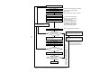
INTRODUCTION
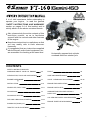
The O.S. FT-160 (Gemini-160) is a horizontallyopposed twin-cylinder overhead-valve four-strokecycle engine of 26.5cc (1.62cu.in) displacement.
The horizontally-opposed layout, typical of modern
light aircraft engine design, provides very smooth
running qualities and docile, trouble-free handling
characteristics.
Quantity
Description
3
Woodruff key
4
Valve adjusting tool kit
5
Hexagonal (Allen) Key (4mm)
6
Choke valve rod
1
1
1
1
6
5
4
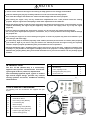
TOOLS AND ACCESSORIES
2-2
The following tools and accessories are supplied with your
engine.
1-3
1-4
1-2
1
3
No.
1
Description
Quantity
2
Radial Motor Mount Set
1-1
Radial Motor Mount
1
1-2
Mount fixing screw (M5X25)
4
1-3
Lock washers (ø5)
4
1-4
Blind nuts (M5)
4
1-5
Engine Fixing Screw (M4X22)
4
2
Set of leads for wiring glow plugs
2-1
Leads for glow plug with clip
2
2-2
Lead for earth (ground)
1
2-1
1-1
1-5
5
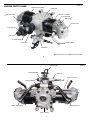
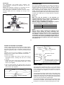
Photo 1
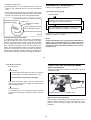
ENGINE PARTS NAME
Photo. 2
Right (No.2) Cylinder
Crankcase
Aluminum tube
Left (No.1) Cylinder
Cylinder Head
Glow Plug
Rocker Cover
Propeller Nut
Lock Nut
Propeller Washer
Drive Hub
Exhaust Pipe
Carburetor
Aluminum tube is not supplied with the engine.
6
Photo. 3
Choke Valve
Intake Manifold
Fuel Inlet
Push Rod Cover
Breather Nipple
Intake Pipe (Right)
Intake Pipe (Left)
Rear Housing
7
INSTALLATION
Needle-valve extension
It is essential that the firewall is strong and rigid (e.g. at
least 15mm thick) and firmly integrated with the structure of
the aircraft.
The needle-valve with this engine is designed to incorporate
an extension so that, when the engine is enclosed within the
fuselage, the needle-valve may be adjusted from the
outside. An L-shaped rod, of 1.6-1.8mm dia. and
appropriate length, should be inserted into the needle's
centre hole and secured by tightening the set-screw in the
needle-valve knob with the small Allen key provided. For
longer extension, it is recommended to use the extension
cable with the engine, together with the knob and support
hook also. For this purpose, Needle Valve Extension Cable
Set (Code No. 72200080) is available as an optional part.
In the interests of scale appearance, the engine should be
installed with the carburetor below the crankcase so that
the exhaust pipes point downwards.
Centre mark
M5 Blind nut
Do not use an excessively long unsupported extension as
this may vibrate and cause the needle-valve setting to vary
or even damage the needle-valve thread. Always provide a
suitable support at the outer end.
Centre mark
M5x25 screw
Set-screw
Set-screw
Firewall
Hook
5 Lock washer
At least 15mm (0.6")
rigid hard wood
Needle
Cable
Knob
Fig. 1
Fig. 2
8
Exhaust pipe adjustment
Choke valve
Unscrew the cap screw while holding the hexagon nut with
6mm wrench, and re-fit the lever to required location.
If the rod is too long, reduce it to required length.
A needlessly lengthy rod may vibrete. The rod should be as
short as possible or have its outer end supported.
Set-screw
Fig. 5
The direction of the exhaust 12mm wrench
pipes may be altered in
accordance with individual
installation requirements. The
angle is easily adjusted by
loosening the nut that secures Loosen
the exhaust pipe to the cylinder
head. Use the 12mm wrench
Lock nut
supplied.
The choke valve operating lever can be located rught or left
by reversing the hexagon nut nd cap screw.
Fig. 3
Tighten
Exhaust pipe
Carburetor cleanliness
It is recommended that the fuel is passed through a filter
when the tank is filled and that a good in-line filter is
installed between the fuel tank and carburetor.
Cap screw
Choke lever
Hex. nut
Occasionally remove the needle-valve holder from the
carburetor and rinse out the locaions shown in Fig. 6 and
Fig. 7 with methanol or fuel. Be careful not to lose the
gasket when removing the needle-valve holder from the
carburetor.
Choke rubber pad
Fuel inlet
The fuel inlet nipple on the carburetor can be adjusted to the
most suitable position for connecting to the fuel delivery tube
from the tank. Slacken the needle-valve holder with the 8mm
wrench provided, reset the inlet nipple at the required angle
and re-tighten.
Fig. 6
Fuel inlet
Slacken with 8mm wrench
Needle-valve
Squeeze bottle
Fig. 7
Dirt and fibrous matter
mostly accumulate here.
Dirt and fibrous matter
mostly accumulate here.
Needle-valve holder
Fig. 4
9
Carburetor
PROPELLER
The needle-valve and throttle lever locations are
interchangeable by reversing the carburetor. This can be
done as follows:
Remove the carburetor carefully by unscrewing the two
screws which secure both carburetor and choke valve.
After reversing the carburetor, re-insert it into the intake
manifold, taking care not to damage the O-ring in the
manifold.
The choice of propeller depends on the design and weight of
the aircraft and on the type of flying in which you will be
engaged. Determine the best size and type after practical
experimentation. As a starting point, refer to the props listed in
the accompanying table. Slightly larger, or even slightly
smaller, props than those shown in the table may be used, but
remember that propeller noise will increase if blade tip velocity
is raised, due to higher rpm or if a larger-diameter / lower-pitch
prop is used.
Photo. 4
Choke valve
Warning:
Make sure that the propeller is well balanced. An
unbalanced propeller and / or spinner can cause serious
vibration which may weaken parts of the airframe or
affect the safety of the radio-control system.
DO NOT forget the WARNINGS and NOTES on propeller
and spinner safety given on pages 2,3 and 4.
Carburetor retaining screw
Type
Sport/Scale
Size (DxP)
16x8, 18x6-8, 20x6
NOTE:
Make a habit of always checking the tightness of the
propeller before starting the engine. Remember that,
especially with wooden propellers, there is a tendency for
the material to shrink, or for it to be reduced by the
serrated face of the drive hub. Retighten the propeller nut
if necessary after loosening the Safety Propeller Locknut.
The licknut should be tightened firmly after retightening
the propeller nut.
Intake manifold
10
PROPELLER & SPINNER ATTACHMENT
Propeller washer
There is a risk, particularly with powerful four-stroke engines,
of the propeller flying off if the prop nut loosens due to
detonation ("knocking") in the combustion chamber when the
engine is operated too lean, or under an excessively heavy
load.
Obviously, this can be very hazardous. To eliminate such
dangers, the O.S. Safety Locknut Assembly was devised.
Install this as follows:
Propeller nut
Locknut
Propeller washer
Locknut
1. Ream the propeller shaft hole to 12mm bore with an
appropriate reamer, checking that the hole is exactly
centered.
2. Install the prop to the engine shaft, followed by the retaining
washer and prop nut and tighten firmly with a 17mm
wrench. (not supplied).
Propeller nut
3. Add the special tapered and slotted locknut and secure
with a 12mm wrench while holding the prop nut with the
14mm wrench. (not supplied).
To be equal
To be equal
Fig. 9
Drive hub
Back-plate of spinner
Drive hub
The Safety Propeller Locknut can
be used provided that the width is
between 21.5mm and 26mm.
FUEL TANK
The suggested fuel tank size is 400cc or 14 oz. This will give
approximately 10 minutes running time at full power, or about
13-15 minutes when some part-throttle operation is included.
Fuel consumption also depends, of course, on the size of
propeller used.
Fig. 8
The ideal fuel tank location is with the top of the tank 5-10mm
(1/4-3/8") above the needle valve. However, model design will
usually require the tank to be located higher than this and there
should be no trouble with such a tank location provided that
you do not pursue spectacular aerobatic flight.
If the tank is located high, fuel will flow into the carburetor when
the tank is full. Therefore, pinch the fuel line with a clip, when
the engine is not running, to prevent flooding and loss of fuel.
Ream to 12mm dia.
11
GLOWPLUGS
The FT-160 is supplied with an O.S. Type F glowplug,
specially designed for O.S. four-stroke engines.
When to replace the glowplug
Apart from when actually burned out, a plug may need to be
replaced because it no longer delivers its best performance,
such as when:
Filament surface has roughened and turned white.
The role of the glowplug
With a glowplug engine, ignition is initiated by the application
of a 1.5-volt power source. When the battery is disconnected,
the heat retained within the combustion chamber remains
sufficient to keep the plug filament glowing, thereby continuing
to keep the engine running. Ignition timing is 'automatic' :
under reduced load, allowing higher rpm, the plug becomes
hotter and, appropriately, fires the fuel/air charge earlier;
conversely, at reduced rpm, the plug becomes cooler and
ignition is retarded.
Filament coil has become distorted.
Foreign matter has adhered to filament or plug body has
corroded.
Engine tends to cut out when idling.
Starting qualities deteriorate.
Glowplug life
Particularly in the case of very high performance engines,
glowplugs must be regarded as expendable items.
However, plug life can be extended and engine performance
maintained by careful use, i.e.:
Install a plug suitable for the engine.
Use fuel containing a moderate percentage of nitromethane
unless more is essential for racing events.
Do not run the engine too lean and do not leave the battery
connected while adjusting the needle.
12
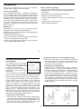
Ni-Cd (nickel-cadmium) 1.2-volt rechargeable battery
Use a 10-Ah cell, or 8 to 10 1.2-Ah cells (as commonly used
for electric-powered R/C cars) wired in parallel and with
short heavy leads (to minimize voltage drop) to the
connection point on the fuselage.
GLOWPLUG HEATING
Glowplug battery
Fig. 9
It is necessary to use a glowplug
battery of fairly large capacity (10Ah
or more) as this is required to heat
four glowolugs simultaneously.
A heavy-duty 1.5-volt dry battery or
(preferably) 1.2-volt Ni-Cd battery Heavy-duty dry batteries
may be used.
Lead-acid 2-volt rechargeable cell
A lead-acid cell of 10-Ah (preferably greater) capacity is
required. However, in this case, it is necessary to reduce
the applied voltage at the glowplugs to approximately 1.5
volt. The recommended method is to insert a suitable
resistor in each individual plug lead. It is possible, of course,
to use a rheostat attached to the 2-volt cell, or to use extra
long leads (at least 2 metres) to obtain the required voltage
drop. However, the disadvantage of this method is that if
one glowplug should fail or become disconnected, voltage
to the other three will be increased with the risk of burning
out their elements.
A 2-volt lead-acid cell (accumulator) may also be used but
only if porvision is made for reducing the voltage at the plugs
since these are nominally rated at 1.5-volt. See notes below.
The two glowplug leads supplied with the engine should be
brought together (Fig.13) and connected to a conveniently
located common external point on the fuselage. This can
either be a terminal with a separate terminal for the earth
(ground) lead (Fig.10) or a suitable socket or jack with
connections for both glowplug and earth (ground) leads
(Fig.11) . Note that the earth (ground) lead supplied is much
heavier (2.0 mm 2 multi-strand copper core) than the plug
leads as this has to have the capacity to carry the current for
all two plugs. Similar wire should be used if a single lead is
employed to extend the glowplug leads (Fig.13).
1. Fit terminals to the fuselage. 2. Fit a jack to the fuselage.
1.5V
Heavy-duty 1.5-volt dry battery
Use at least four heavy-duty cells wired in parallel (Fig.9)
and with short heavy leads (to minimize voltage drop) to the
connection point on the fuselage. The disadvantage of dry
cells is that they cannot be recharged when their power
diminishes and makes the engine difficult to start.
Fig.10
13
1.5V
Fig.11
Glowplug leads
The plug leads are fitted with special snap-on connectors
that ensure firm contact with O.S. plug. They are a "click" fit
and are not suitable for use with most other makes of
glowplug.
If glowplug leads are extended together as a single cable,
use heavier wire, e.g. 2.0 mm 2 multi-strand copper core as
supplied for earth lead.
2.0mm
2
The earth (ground) lead is fitted with a plug terminal which
should be connected to the engine by means of one of the
mounting screws.
Make sure that no part of the wiring touches the cylinder
head or cooling fins.
Fasten to the
motor mount.
Keep wiring away from the fuel tank where it might cause a
fire in the event of a short-circuit.
Earth lead
Fig.12
Install Ni-Cd battery in the fuselage, and switch on or off by
means of transmitter. (On-board battery)
Fig.13
Glowplug re-heat
Under normal conditions, the FT-160 will idle sufficiently
slowly with the throttle closed to permit a safe landing
approach. However, if conditions (atmospheric, fuel, tank
location etc.) are unfavourable, there may be a tendency for
one cylinder to cease firing if the engine is throttled down to a
very low idling speed. This can be prevented by installing a
small on-board Ni-Cd battery which will automatically re-heat
the glowplugs when the engine is throttled down to idling
speed (Fig.12). A suitable switch should be installed so that it
is actuated by the throttle servo only when the engine is
throttled down. Safe idling speeds of less than 1,800 rpm may
be obtained in this way and without undue drain on the
battery.
Switch should have
sufficient capacity.
1.2 volt Ni-Cd battery with
more than 6 Ah capacity.
14
FUEL AND LUBRICATION
STARTING
Fuel
The FT-160 should be operated on a methanol based fuel
containing not less than 18% (volumetric) castor oil, or a top
quality synthetic lubricant (or a mixture of both), plus a small
percentage (5-20%) of nitromethane for improved flexibility
and power.
Precautions
For safety, please observe the following instructions before
starting the engine.
Reminder!
Model engine fuel is poisonous. Do not allow it to
come into contact with the eyes or mouth. Always
store it in a clearly marked container and out of the
reach of children.
Do not start the engine with the throttle fully opened,
otherwise the model will tend to move forward suddently due
to the strong thrust of the propeller. Hold both wings of the
model when starting the engine.
Start the engine by turning the propeller counter-clockwise
(i.e. normal running direction).
Do not carry out carburetor adjustments (except needlevalve adjustment) while engine is running.
Model engine fuel is also highly flammable. Keep it
away from open flame, excessive heat, sources of
sparks, or anything else which might ignite it. Do not
smoke, or allow anyone else to smoke, near to it.
Use a high-torque electric starter.
Starting procedure is as follows:
1. Open the needle-valve 3 to 3.5 turns from the fully closed
position (Fig.14).
Lubrication
All parts of the FT-160 are automatically lubricated by the oil
content of the fuel mixture.
The crankcase breather hole is located at the side of the
engine and is fitted with a brass nipple. (See photo 3 on page
7.) Fit a length of silicone tubing of approx. 2.5-3mm I.D. to
this nipple to conduct away the small amount of oil that
escapes through the breather.
open 3 to 3.5 turns.
Fig.14
Make a habit of draining out the excess oil in the crankcase
at the end of each flying session. Leaving contaminated oil in
the crankcase for a long time will cause rust. Also, residual
castoroil will tend to solidify and lock the engine. Inject
corrosion-inhibiting oil into the crankcase to neutralize the
effects of any remaining contaminants.
15
2. Make sure that glowplugs are not connected to the battery.
Do not heat the glowplugs while priming. (Fig.15).
If very strong compression is felt when trying to turn the
propeller counter-clockwise, too much fuel has been drawn
into the engine. In this case, do not use force, but release
the choke valve and turn the propeller clockwise slowly to
eject excess fuel through exhaust pipes.
Do not connect the battery to
the glowplugs while priming.
Fig.18
Fig.15
Do not apply the starter with the choke closed.
Warning! Never close the choke valve when applying the
starter. Such an action will cause an excess quantity of fuel
to be drawn into the cylinder and result in hydraulic lock that
may damage the engine. (Fig.18)
3. Open the throttle valve fully, close the choke valve and turn
the propeller counter-clockwise through three revolutions.
(Fig.16 & 17)
Fig.16
Fig.17
Excess fuel in the carburetor may drip into the engine
compartment when the choke valve is reopened. Therefore,
it is advisable to drill a drain hole in the bottom of the engine
bay or cowling and to apply fuelproof paint to the
surrounding surfaces to prevent fuel from penetrating the
airframe structure.
Close the choke valve.
Open the throttle fully.
4. Release the choke
control and immediately
turn
the
propeller
counter-clockwise
several times so that fuel
is drawn well into the
cylinders (Fig.19).
Turn 3 revolutions.
Fig.19
16
5. Set the throttle valve
approximately 1/4 open from
the fully closed position.
(Fig.20).
8. Make sure that all two cylinders are firing
Fig.20
The engine is running properly if white smoke is emitted
through all four exhaust pipes. A slight spray of fuel will be
discharged through the exhaust pipe or any cylinder that is
not firing.
Fully closed
Fully open
Set at this position
6. Starting with an electric
starter (Fig.21)
If a cylinder ceases firing, reduce the throttle setting to
approximately 1/4 open from the fully closed position and
re-connect the glowplug battery. Revolutions will increase
when all cylinders are firing steadily.
Make sure that the direction of rotation of the starter is
correct.
Connect the glowplug battery.
Fig.23
Apply the electric starter.
Connect the battery to the glowplug.
Fig.21
Make sure that the direction
or rotation is correct.
Electric starter
7. When the engine starts,
open the throttle valve fully
and keep it running initially
(approx. 10 seconds), with
original needle-valve setting.
A slight spray of fuel may be emitted through the exhaust
pipe if a cylinder is not firing.
Fig.22
9. Now disconnect the glowplug battery.
Open the throttle fully.
17
10. Adjust the needle-valve
RUNNING-IN ("Breaking-in")
Abrupt adjustment of the needle-valve may cause the
engine to stop, especially when it is new and insufficiently
run-in.
Obtain a 18x6 propeller for running-in.
1. Running-in on the ground
As the speed of the engine does not instantly change with
needle-valve readjustment, small movements, with pauses
between, are necessary to arrive at the optimum setting.
Start the engine
↓
1
Practical best (optimum) needle-valve setting
Close the needle-valve
Approx. 40
gradually and slowly.
Maximum rpm setting
("Lean")
↓
2
"Rich" needle-valbe setting
when starting the engine.
Engine stops.
Set the needle-valve at 500-1,000r.p.m. lower than
maximum r.p.m. setting and run approx, 10 seconds.
(It is suggested to use a tachometer.)
Open the needle-valve at approx. 1,000r.p.m. lower
than above setting and run approx. 20 seconds.
Revolutions start to decrease.
Repeat above procedure, while increasing the setting 1 r.p.m.
gradually, for approx. 10 minutes.
Fig.24
Re-starting the engine when warm
NOTE:
To re-start the engine when warm, simply re-energise the
plugs and reapply the starter with the throttle in the idling
position. If the engine does not start, disconnect the battery
from the glowplugs and re-prime by closing the choke valve
while rotating the propeller twice with the throttle open.
Initially, the high temperature inside the combustion chambers
may turn the liquid fuel into gas and emit it through the
exhaust pipes. Therefore, repeat the priming procedure once
or twice until the cylinders become cool enough for restarting.
Keep the throttle fully open, using only the needle-valve to
change r.p.m. Prolonged running-in on the ground is not
suggested because the purpose is just initial running-in
to increace engine temperature gradually close to that of
maximam r.p.m.
18
2. Running-in in the air
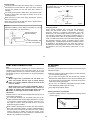
THROTTLE VALVE ADJUSTMENT
Start the engine
Needle-valve adjustment
Adjust the needle-valve following the instructions given in
STARTING section.
Fly the model.
Set the needle-valve approx 40 open from optimum
position (approx. 40 open from maximum r.p.m.).
Mixture control screw
Photo. 5
NOTE: Avoid prolonged heavy load flight.
With each successive flight, close the needle-valve
slightly, until, at the end of 10 flight, the needle-valve is
set for optimum position.
Needle-valve
Fuel inlet
Finish running-in.
The carburetor can now be adjusted for optimum throttle
performance following the instructions given in the next
section.
Throttle stop screw
Choke valve
Mixture control valve adjustment
After running is completed and the needle-valve is set at
optimum position (approx 40 open from maximum r.p.m.
position), check the idling running and adjust only when
necessary.
19
Start the engine.
open the throttle fully .
Adjust the neede-valve.
Disconnect the glowplugs from the battery.
Approx 40˚ open from maximum
r.p.m. setting.
Make sure that all 2 cylinders are firing.
Close the throttle gradually.
Find the idling position.
Fix the idling position.
Re-set the idling position at
a little higher r.p.m.
Open the throttle fully.
Engine stops.
Does the engine
regain full power?
The position where the lowest
possible r.p.m. ,with steady
running, is obtained.
Set the throttle opening by
means of the throttle trim on
the transmitter so that the lowest
practical speed, without risk of
the engine stopping,is obtained.
Make sure glowplug heat is switched.
The engine hesitates before picking
up to full speed, or appears to run at
medium speed with reduced power.
20
Yes.
Continue running at high speed
for 5 seconds.
Check mixture adjustment at idling
speed. Make sure that all cylinders
are firing.
Adjustment should be carried
out after stopping the engine.
Run at idling speed for 5 seconds.
Does the engine stop?
Engine stops.
No.
Apply full throttle.
Does the engine
regain full power
immediately?
Yes.
OK
Repeat the procedure while opening and closing the
throttle until the best result is obtained.
Close the throttle.
Attention: Do not leave the battery connected while adjusting the carburetor.
Do not move needle-valve
while adjusting other controls.
Adjusting the mixture control valve
of the + mark about 1/12 turn (30 ). Normal safe idling
speeds are in the region of 2,000 r.p.m..
1. If the engine hesitates, puffing out Mixture Control Screw
a good deal of smoke, before
picking up to full speed, it is
Turn 30
probable that the idling mixture is
too rich.
In this case, it will be necessary
Screwdriver
to turn the Mixture Control Screw
Fig.25
in the reverse direction from the +
mark (i.e. clockwise) to weaken the mixture. About 1/12
turn (30 ) should be sufficient (Fig. 25).
2. Alternatively, if the engine stops
or is slow to pick up speed,
without smoking or a strong
exhaust note, it is probable that
the idling mixture is too lean.
NOTE:
As this is two-cylinder four-stroke-cycle engine, firing
strokes occur every half revolution (360 ), that is, two
firings take place every one complete revolution.
Therefore, at first you may have an impression that the
engine is idling at higher r.p.m. than actual running r.p.m.
It is recommended to check the engine r.p.m. with a
tachometer.
Changing the make of glowplug or fuel may sometimes
require re-adjustment of carburetor throttle.
Fig.26
Realignment of mixture control screw
In the course of making carburetor adjustments, it is just
possible that the Mixture Control Screw setting may be
upset.Its basic setting can be re-established as follows:
In this case, it will be necessary
Turn 30
to turn the Mixture Control Screw
in the direction of the + mark (i.e.
counter-clockwise) approximately 1/12 turn (30 ) (Fig. 26).
Carefully turn the screw in the
With the basic position of
the screw, this pin is located direction of the + mark with
the screw-driver supplied until
at the centre.
it stops, then turn back again
(The pin is seen if the
throttle lever is removed.) exactly two revolutions.
3. Thirdly, if revolutions increase but the engine appears to
run with reduced power, it is probable that one of the
cylinders has ceased firing. You may detect this by the
difference in exhaust note and revolutions compared with
previous full-throttle running. The cutting out of the cylinder
may be caused by the idling speed being set too low or the
idling mixture being too rich.
Fig.28
Fig.27
+ mark
Throttle lever
NOTE:
If an on-board glowplug re-heat system is fitted, mixture
adjustment at idling speed should be carried out with this
in operation.
In the case of the idling speed being too low, re-set the
idling position a little higher by means of the throttle trim on
the transmitter. In the case of the idling mixture being too
rich, turn the Mixture Control Screw in the reverse direction
21
3. Do not close the needle-valve to too "lean" a setting. This
will cause the engine to overheat and slow down and also
will generate much nitromethane oxide due to extremely
high temperature which will cause internal rusting of the
engine. Always adjust the needle-valve very slightly to the
"rich" side of the peak r.p.m. setting.
FLIGHT
Checking before flight
Make sure that all two cylinders are firing.
Make sure that engine runs steadily at idling speed.
Make sure that engine is fully warmed up.
It is necessary to warm up the engine as with a full-size
aircraft or automobile. Do not attempt to take-off immediately
after the engine has been started. Allow the engine to run at
full throttle for at least 10 seconds before releasing the
model.
4. Clean the exterior of the engine with a clean cotton cloth. If
this is not done, oil and dirt will burn onto the outside of the
engine each time it is run and the engine will soon become
blackened
5. If the engine is not in use for a while (more than two months)
remove the glowplugs and rinse out the interior with
kerosene (not gasoline), by rotating the crankshaft. Shake
out residue, then inject corrosion-inhibiting oil (preferably) or
light machine-oil through glowplug cabities and breather
hole, again rotating the shaft to distribute the protective oil to
all working parts.
CARE AND MAINTENANCE
To ensure that you obtain long life and peak performance from
your engine, observe the following
1. Avoid running the engine under dusty conditions. If
necessary, lay a sheet of plywood or hardboard in front and
under the nose of the model when starting the engine.
2. Foreign matter in the fuel can cause the carburetor jet to be
partially clogged.
Therefore:
rinse out the fuel tank with methanol or fuel before
installing it
fit a fuel filter in the uel delivery tube between tank and
carburetor
fit a fuel filter to pump inlet of the manual or electric fuel
pump
do not leave your fuel container open needlessly
check filters periodically and clean them when necessary
22
VALVE CLEARANCE ADJUSTMENT
ALL O.S. four-stroke engines have their valve (tappet)
clearances correctly set before they leave the factory.
However, if, after many hours of running time have been
logged, a loss of power is detected, or if the engine has to
be disassembled or repaired as a result of an accident,
valve clearances should be checked and readjusted, as
necessary, with the aid of the O.S. Valve Adjusting Tool Kit.
2. Remove all the glowplugs except the one fitted to the
cylinder that you want to check.
Note:
Each glowplug should be re-fitted to the original cylinder.
You may start to check and adjust with any cylinder.
3. Turn the propeller counter-clockwise until compression is
first felt, then turn it futher quarter turn. At this point, both
valves should be closed. (If the prop driver ('drive hub') of
your engine is engraved with a letter 'T', this mark should
now be at the top.)
The kit comes in a plastic case and includes:
Hex. key 1.5mm
Feeler gauge 0.04mm
Feeler gauge 0.1mm
4. The standard valve clearance, on both inlet and exhaust
valves, is between 0.04mm and 0.1mm(0.0015-0.004 inch),
measured between valve stem and rocker arm. Use the
0.04mm and 0.1mm feeler gauges to check clearances.
(See Fig.29.)
Wrench 5mm
0.04mm Feeler Gauge
Note:
Valve clearances of all O.S. four-stroke-cycle engines
must be checked and reset ONLY WHEN THE ENGINE IS
COLD. Procedure is as follows:
Rocker Arm
Valve
1. Remove the rocker cover from each cylinder head by
unscrewing two socket-head cap-screws from the rocker
box on top of the cylinder head with Allen key supplied.
Fig.29
23
2. Turn adjusting-screw approx. 1/2 turn counter-clockwise to
open gap, using appropriate tool -i.e. Allen hex key.
(Fig.31.)
Note:
If the gap is found to be less than 0.04mm, it is not
necessary to readjust the clearance if the engine has
good compression and starts easily. Equally, if the gap
exceeds 0.1mm but is not more than 0.14mm (i.e. the
thickness of both feeler gauges inserted together), it is
not necessary to readjust the clearance if the engine
runs satisfactorily.
Adjusting Screw
Turn approx.1/2 turn.
Allen Key
If a clearance is found to be outside either of these limits, it
should be reset as follows.
1. Carefully loosen the locknut on rocker-arm 1/4-1/2 turn with
5mm wrench. (Fig.30.)
Fig.31
3. Insert 0.04mm feeler gauge between valve stem and rockerarm and gently turn adjusting screw clockwise until it stops.
(Fig.32.)
Slacken approx.1/4 to 1/2 turn.
Locknut
Turn with fingers until it stops.
Wrench
0.04mm Feeler Gauge
Fig.30
Fig.32
24
4. Re-tighten locknut while holding adjusting screw stationary.
(Fig.33.)
Hold at the screw head.
Tighten Locknut.
Fig.33
5. Remove 0.04mm feeler, rotate prop through two
revolutions and recheck gap.
6. If clearance is correct, loosen the locknut on the other
rocker-arm and repeat steps 1 to 5 above. Finally, replace
rocker box cover.
Remember:
Excessive valve clearance will cause loss of power, due
to valve (s) not opening sufficiently. On the other hand, a
total loss of clearance may cause difficult starting due to
valves not closing properly, resulting in loss of
compression.
25
EXPLODED VIEW
36
C.M3x16
C.M4x22
29
28
C.M3.5x12
39
1
30
29-1
31
37
M3
35
8
34
38
27
6
26
C.M3.5x10
33
12-2
6-2
6-3
1
12-1
6-4
14
5-2
5
13
24
3
C.M3.5x15
5-1
13-1 13-2
9-2
9-1
9-3
3-1
3-2
32
12
2
23
17
C.M3x15
19
6-1
22
4-2
4-1
C.M3.5x20
9-2
10
9
7
25
11
C.M3x8
21
16-2 16-1
16-3
16
4
15
1
20
C.M2.6x7
18
Type of screw
C...Cap Screw M...Oval Fillister-Head Screw
F...Flat Head Screw N...Round Head Screw S...Set Screw
N.+M3x22
26
PARTS LIST
No.
Code No.
1
2
3
3-1
3-2
4
4-1
4-2
5
5-1
5-2
6
6-1
6-2
6-3
6-4
7
8
9
9-1
9-2
9-3
10
11
12
12-1
12-2
13
13-1
13-2
14
15
46013002
46104200
45961400
45961410
45761600
45361000
45361100
45061202
46169000
46169100
45169200
46160000
46160100
45460200
45060309
46160400
46104110
46104020
46168000
46168010
45115000
46115000
46481000
46184000
46168100
46168110
45169200
46168200
46168210
45169200
46168500
46166000
Description
Screw Set
Rocker Cover
Rocker Support Assembly
Rocker Support
Rocker Arm Retainer (2pcs.)
Rocker Arm Assembly (1pair)
Rocker Arm (1pc.)
Tappet Adjusting Screw
Exhaust Pipe Assembly
Exhaust Pipe
Exhaust Pipe Lock Nut
Valve Assembly (1pair)
Valve (1pc.)
Valve Spring (1pc.)
Spring Seat (1pc.)
Valve Spring Retainer (2pcs.)
Cylinder Head (W/Gasket)
Cylinder Head (W/Valve Assembly)
Intake Manifold Assembly
Intake Manifold
Intake Pipe "O" Ring (2pcs.)
Carburetor Rubber Gasket
Carburetor Complete
Choke Valve Assembly
Intake Pipe Assembly (right)
Intake Pipe (right)
Intake Pipe Lock Nut
Intake Pipe Assembly (left)
Intake Pipe (left)
Intake Pipe Lock Nut
Intake Boots (2pcs.)
Push Rod (2pcs.)
No.
Code No.
16
16-1
16-2
16-3
17
18
19
20
21
22
23
24
25
26
27
28
29
29-1
30
31
32
33
34
35
36
37
38
39
45566100
45566110
45566300
24881824
45564000
45403400
45903200
45906000
46105000
46114000
46103100
46103300
46031005
46162000
22631019
46110100
46108000
45508200
46120000
26731002
46101000
22130004
46102000
46030008
46101800
45471000
71615009
71910000
72200090
72200060
Description
Push Rod Cover Assembly (2pcs.)
Push Rod Cover (1pc.)
Push Rod Cover "O" Ring (L) (2pcs.)
Push Rod Cover "O" Ring (S) (2pcs.)
Cam Follower (2pcs.)
Piston Ring
Piston
Piston Pin
Connecting Rod Assembly
Head Gasket Set (2pcs.)
Cylinder Liner
Cylinder Jacket
Camshaft Bearing (front)
Camshaft
Camshaft Bearing (rear)
Propeller Locknut Set
Drive Hub
Woodruff Key
Thrust Washer
Crankshaft Bearing (front)
Crankcase
Crankshaft Bearing (intermediate)
Crankshaft
Crankshaft Bearing (rear)
Rear Housing
Breather Nipple (No.4)
Glow Plug Type F
Radial Motor Mount Set
Booster Cable Set
Valve Adjusting Kit
The specifications are subject to alteration for improvement without notice.
27
CARBURETOR EXPLODED VIEWS & PARTS LIST
S.M3x3
1
2
5
6
2-1
3-1
S.M3x3
3
4-1
S.M3x3
4
8
7-1
7
10-1
10-2
S.M3x3
10
9-6
9-5
9-7
9-2
9-4
11
9-3
9-1
N.+M3x22
9
Note: The choke valve assembly is not included in the carburettor complete.
Type of screw
C...Cap Screw M...Oval Fillister-Head Screw
F...Flat Head Screw N...Round Head Screw S...Set Screw
No.
Code No.
1
2
2-1
3
3-1
4
4-1
5
6
7
7-1
8
9
9-1
9-2
9-3
9-4
9-5
9-6
9-7
10
10-1
10-2
11
26381501
24981405
26381501
46481320
22781800
46481330
26381501
46481200
46281340
46481310
22781800
46481100
46281900
29081952
24981837
26381501
46181940
46181941
46181950
26711305
26781619
26681305
26681803
45581700
Description
Set-screw
Throttle Lever Assembly
Set-screw
Mixture Control Screw Assembly
"O" Ring (2pcs.)
Mixture Control Screw Holder Assembly
Set-screw
Carburetor Rotor
Mixture Control Valve Pin
Mixture Control Valve Assembly
"O" Ring (2pcs.)
Carburetor Body
Needle Valve Assembly
Needle Assembly
"O" Ring (2pcs.)
Set-screw
Needle Valve Holder Assembly
Needle Valve Holder
Fuel Inlet
Ratchet Spring
Throttle Stop Screw Assembly
Throttle Stop Screw
Throttle Stop Screw Holder
Carburetor Retaining Screw
The specifications are subject to alteration for improvement without notice.
28
O.S. GENUINE PARTS & ACCESSORIES
RADIAL MOTOR MOUNT
(71910000)
5/16"-M5 (L) PROPELLER
LOCKNUT SET FOR SPINNER
BLIND NUT (10pcs.)
(46110200)
M5
M5
(79870050)
(55500004)
LOCK WASHER (10sets)
O.S.GLOW PLUG TYPE F
(71615009)
BOOSTER TERMINAL KIT
BOOSTER CABLE SET
(72200130)
(72200090)
NEEDLE VALVE
EXTENSION CABLE SET
NON-BUBBLE WEIGHT
(71531000)
(72200080)
VALVE ADJUSTING
TOOL KIT
(72200060)
SUPER FILTER (L)
CAP SCREW SET (10pcs.)
(72403050)
M2.6x7
M3.5x10
M3.5x12
M3.5x15
M3.5x20
(79871020)
LONG SOCKET WRENCH
WITH PLUG GRIP
(71521000)
(79871070)
(79871080)
(79871090)
(79871100)
The specifications are subject to alteration for improvement without notice.
29
Specifications
Displacement
Bore
Stroke
PracticalR.P.M.
Output
Weight
63.5
50.5
THREE VIEW DRAWING
13.26cc x 2 / 1.218cu.in. x 2
27.7mm / 1.091in.
22.0mm / 0.866in.
2.000-10.000r.p.m.
1,100g / 38.8oz.
4 -5.2
120
56.5
54
23.5
68
76
196
Dimensions(mm)
30
6-15 3-Chome Imagawa Higashisumiyoshi-ku
Osaka 546-0003, Japan TEL. (06) 6702-0225
FAX. (06) 6704-2722
URL : http://www.os-engines.co.jp
C Copyright 2004 by O.S.Engines Mfg. Co., Ltd. All rights reserved. Printed in Japan.
60090531 040501