1
It is of vital importance, before attempting to operate your engine,
to read the general 'SAFETY INSTRUCTIONS AND WARNINGS'
section on pages 2-4 of this booklet and to strictly adhere to the
advice contained therein.
Also, please study the entire contents of this instruction manual,
so as to familiarize yourself with the controls and other features
of the engine.
Keep these instructions in a safe place so that you may readily
refer to them whenever necessary.
It is suggested that any instructions supplied with the aircraft,
radio control equipment, etc., are accessible for checking at the
same time.
•
•
•
CONTENTS
SAFETY INSTRUCTIONS AND
WARNINGS ABOUT YOUR O.S. ENGINE
2-4
INTRODUCTION, FEATURES
5
BASIC ENGINE PARTS
6
CONNECTING WITH THE EC-2
(LED Display, Buzzer hotes and status)
7-8
LIST OF 160FX-FI USAGE CONDITIONS
9
BEFORE INSTALLING THE ENGINE
10
INSTALLATION PROCEDURE
10-12
LINKAGE AND INITIAL SETTINGS
13-14
ENGINE STARTING AND
AIR-FUEL MIXTURE ADJUSTMENT
14
ENGINE STARTING
15-16
FLIGHT ADJUSTMENT
17
GLOW PLUG, CARE AFTER USE
18
TROBLESHOOTING
19
ENGINE & INJECTOR AIR VALVE
EXPLODED VIEW
20
PARTS LIST
21
THREE VIEW DRAWING
22
O.S. GENUINE PARTS & ACCESSORIES
23
MEMO
24
1
SAFETY INSTRUCTIONS AND WARNINGS ABOUT YOUR O.S. ENGINE
Remember that your engine is not a " toy ", but a highly efficient internalcombustion machine whose power is capable of harming you, or others, if it is
misused or abused. As owner, you, alone, are responsible for the safe operation
of your engine, so act with discretion and care at all times.
If at some future date, your O.S. engine is acquired by another person, we would
respectfully request that these instructions are also passed on to its new owner.
■ The advice which follows is grouped under two headings according to the
degree of damage or danger which might arise through misuse or neglect.
WARNINGS
NOTES
These cover events which might involve
serious ( in extreme circumstances, even fatal )
injury.
These cover the many other possibilities,
generally less obvious sources of danger, but
which, under certain circumstances, may also
cause damage or injury.
WARNINGS
• Never touch, or allow any object to come into contact with, the rotating
propeller and do not crouch over the engine when it is running.
• A weakened or loose propeller may disintegrate or be thrown off and, since propeller
tip speeds with powerful engines may exceed 600 feet(180 metres) per second, it will
be understood that such a failure could result in serious injury, (see 'NOTES' section
relating to propeller safety).
• Model engine fuel is poisonous. Do not allow it to come into contact with
the eyes or mouth. Always store it in a clearly marked container and
out of the reach of children.
• Model engine fuel is also highly flammable. Keep it away from open flame,
excessive heat, sources of sparks, or anything else which might ignite it.
Do not smoke or allow anyone else to smoke, near to it.
• Never
operate your engine in an enclosed space. Model engines, like automobile
engines, exhaust deadly carbon-monoxide. Run your engine only in an open area.
• Model engines generate considerable heat. Do not touch any part of your
engine until it has cooled. Contact with the muffler(silencer), cylinder
head or exhaust header pipe, in particular, may result in a serious burn.
2
NOTES
•
This engine was designed for model aircraft. Do not attempt to use it for
any other purpose.
•
Mount the engine in your model securely, following the manufacturers'
recommendations, using appropriate screws and locknuts.
•
Be sure to use the silencer (muffler) supplied with the engine. Frequent
exposure to an open exhaust may eventually impair your hearing.
Such noise is also likely to cause annoyance to others over a wide area.
•
Install a top-quality propeller of the diameter and pitch specified for the
engine and aircraft. Locate the propeller on the shaft so that the curved
face of the blades faces forward-i.e. in the direction of flight. Firmly tighten
the propeller nut, using the correct size wrench.
•
Always check the tightness of the propeller nut and retighten it, if
necessary, before restarting the engine, particularly in the case of fourstroke-cycle engines. A safety locknut assembly is provided. Always use it.
This will prevent the propeller from flying off in the event of a "backfire",
even if it loosens.
•
If you install a spinner, make sure that it is a precision made product and
that the slots for the propeller blades do not cut into the blade roots and
weaken them.
•
Discard any propeller which has become split, cracked, nicked or
otherwise rendered unsafe. Never attempt to repair such a propeller:
destroy it. Do not modify a propeller in any way, unless you are highly
experienced in tuning propellers for specialized competition work such as
pylon-racing.
•
Use an electric starter for this engine. The wearing of safety glasses is also
strongly recommended.
•
Take care that the glow plug clip or battery leads do not come into contact
with the propeller.
Also check the linkage to the throttle arm. A disconnected linkage could
also foul the propeller.
3
NOTES
•
Adjust the throttle linkage so that the engine stops when the throttle stick
and trim lever on the transmitter are fully retarded. Alternatively, the
engine may be stopped by cutting off the fuel supply. Never try to stop the
engine physically.
•
Take care that loose clothing (ties, shirt sleeves, scarves, etc.) do not come
into contact with the propeller.
Do not carry loose objects (such as pencils, screwdrivers, etc.) in a shirt
pocket from where they could fall through the propeller arc.
•
Do not start your engine in an area containing loose gravel or sand.
The propeller may throw such material in your face and eyes and cause
injury.
•
For their safety, keep all onlookers (especially small children) well back (at
least 20 feet or 6 meters) when preparing your model for flight. If you have
to carry the model to the take-off point with the engine running, be
especially cautious. Keep the propeller pointed away from you and walk
well clear of spectators.
•
Warning! Immediately after a glowplug-ignition engine has been run and is
still warm, conditions sometimes exist whereby it is just possible for the
engine to abruptly restart if the propeller is casually flipped over
compression WITHOUT the glowplug battery being reconnected.
Remember this if you wish to avoid the risk of a painfully rapped knuckle!
4
INTRODUCTION
This engine is the MAX-160FX-FI (fuel injection) engine equipped with a
revolutionary fuel supply system that was jointly developed by Futaba, a
manufacturer of Radio control equipment, and O.S. Engines, a
manufacturer of model engines.
This system detects engine speed with a sensor based on throttle
signals transmitted from a transmitter. It then determines the fuel
injection volume based on the required amount of fuel to be supplied for
that engine speed as calculated by an electronic control unit referred to
as the "EC-2", after which fuel is injected into the engine from an
injector. In addition, adjustments can also be made using dial on the
transmitter. The result is an engine for Aerobatic and big scale models
that features excellent engine speed linearity relative to throttle operation
under all types of flight conditions.
FEATURES
Supplies the Proper Amount of Fuel at all Times
•Easier starting
•Greater stability during idling
•Excellent linearity and response relative to stick operation.
Simple Adjustment Using Dials on the Transmitter
•Air-fuel mixture at medium and high speeds can be safety and easily adjusted
from the transmitter.
•Adjustments can be made while on the ground and during flight.
Stable Supply of Fuel at all Times
Pressurized fuel is controlled at a constant pressure with respect to all types of
movement during flight allowing stable engine performance at all times.
Light Weight and Easy Installation
The sensor and injector mounted on the engine are both compact and
lightweight, while the electronic control unit (EC-2) is also lightweight, enabling
various connections to be made easily the same as plugging in a servo.
5
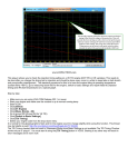
Glow plug No.8
BASIC ENGINE PARTS
Cylinder Head
Accessories
•EC-2 Assembly
•Y harness
•Duble-sided spongebacked cushioning tape
•Check Valve
•Fuel Filter
•Driver to push Limit
Setting Switch
•Glow plug No.8
•E-5010 Silencer
Temperature Sensor
Crankcase
Injector
Air Valve 70C
Pressure Fitting
RPM Sensor
Drive Hub
Beam Mount
Injector
Crankshaft
Electronic Control Unit<EC-2>
Propeller Washer
Propeller Nut
Lock Nut
INSTALLATION OF THE AIR VALVE
As delivered, the engine has its air valve lightly installed into the intake boss. Secure it as follows.
1. Loosen the retainer nut, rotate the air valve to its correct position and make sure that it is pressed
well down into the intake boss, compressing the rubber gasket, before retightening nut.
2. Rotate the retainer nut gently until it stops, then tighten a further 90-120˚.
Do not overtighten the screw as this will damage the thermo insulator.
Injector
✽
Never attempt to disassemble the injector.
It may not be able to be reassembled.
The injector consists of a solenoid valve with built-in regulator. It controls pressurized fuel at a constant
pressure and accurately injects fuel based on signals from the electronic control unit (EC-2).
Temperature Sensor
This measures the temperature of the engine exhaust unit.
RPM Sensor
The RPM sensor is provided with a power generating sensor. When the crankshaft passes in front
of the sensor, the signal that is generated is transmitted to the electronic control unit (EC-2).
Engine speed is then calculated based on that signal which is then used to determine the timing at
which fuel is injected.
Electronic Control Unit<EC-2>
(abbreviated as simply EC-2)
The EC-2 transmits fuel injection signals to the injector to ensure the proper amount of fuel
injection based on basic fuel injection data that has been previously entered and constantly
changes with position of throttle stick.
Check Valve
This one-way valve's function is to pressurize the fuel tank by crankcase
pressure and prevent fuel from returning to the engine crankcase.
Fuel Filter
This fine mesh filter prevents foreigh matter from the fuel tank from plugging
the small injector valve.
Y harness
This cord is used to connect the receiver (throttle channel), throttle servo and EC-2.
6
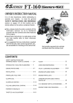
CONNECTING WITH THE EC-2
Connect the receiver and servo-related components (rudder section) in the same manner as in the past.
(8) Integrated Buzzer
(3) Injector output terminal
(INJECTOR)
(4) Temperature sensor input terminal
(Temp)
(5) RPM sensor input terminal
(r.p.m.)
(2) Injection trim input terminal
(AUX:TRIM)
(1) Injection time input terminal
(CH3:THRO)
(6) Limit Setting Switch(LIMIT) (7) L.E.D.
Two extension cords (sold separately) of a length corresponding to the airframe are required for
connecting (1) and (2).
(1) Injection Time Input Terminal<Black> (CH3:THRO)
Connect the y harness provided with the CH3 THRO input terminal to throttle channel of the
receiver (throttle: CH3), connect the wiring connector from the throttle servo to one of the doubleopening connectors on the opposite side, and connect the other double-opening connector to
CH3:THRO of EC-2. (Use the separately sold extension cord if the wiring cords are too short.)
(2) Injection Trim Input Terminal<Red> (AUX:TRIM)
Connect a spare channel for dial use of the receiver (e.g. channel 7) to the AUX:TRIM terminal.
(Use the separately sold extension cord if the wiring cords are too short.)
(3) Injector Output Terminal
Connect the injector connector to the injector output terminal. Protect the lead wire with a heatresistant tube,etc. if it makes contact with the engine mount.
(4) Temperature Sensor Input Terminal
Connect the temperature sensor connector to the temperature sensor input terminal.
(5) Rotation Sensor Input Terminal
(6) Limit Setting Switch(LIMIT)
Connect the rotation sensor connector to the rpm input terminal.
Push with driver supplied when setting limit.
(7) L.E.D.(Display of green and red)
It flashes or changes color when setting and cheking limit, and adjusting injection trim. It flashes with the color of
the injection trim when the engine is running.
LED Display
Transmitter Operation
Turn the dial right to reduce injection volume.
When the engine
is not running
Turn the dial left to increde injection volume.
Flashes
(color depends or the dial position)
Limit position
When the engine
is running
LED Status
Red lights
Green lights
Turn the dial right to reduce injection volume.
Red flashes
Turn the dial left to increde injection volume.
Green flashes
*Turning direction of dial shows the standard setting direction.
*Dial position shows plus (green - rich) or minus (red - lean) from the zero position (basis injection volume.)
7
(8) Integrated Buzzer
Buzzer sounds when setting Limit, dial is set nnetral a error happens.
Buzzer notes and status
Notes
Status
Nil
Normal
One note (Pi)
Limit at Low is set
Two successive notes (PiPi)
Dial neutral
Limit at High is set
*Repeated one note (Pi...Pi...)
Temperature Sensor is disconnected
*Repeated two successive notes (PiPi...PiPi...)
Error on setting Limit
*Repeated three successive notes (PiPiPi...PiPiPi...)
Battery voltage falls down (below 3.8v)
*mark shows alarm for error.
Fig.1
Transmitter
Temperature Sensor
Throttle Servo
Branched Cord
Receiver
Injector
CH3
AUX✽
Rotation Sensor
EC-2
AUX
✽ Spare Channel
Throttle Channel
Injection trim adjustment
corresponds to needle-valve adjustment of conventional carburetor)
Fuel injection volume
Fig.2
Full high
Intermediate slow
1
Lo
2
3
4
5
6
7
8
Mi
9
Hi
(Throttle stick position)
8
Injection trim can be adjusted independently
for two area as shown in the graph.
Intermediate slow and full high are adjusted
with the injection trim adjustment dial (spare
channel dial) on the transmitter.
LIST OF 160FX-FI USAGE CONDITIONS
Part
Name
Manufacturer
Silencer
O.S.
*E-5010
Glow plug
O.S.
*No.8
Propeller
Commercially
available
high-quality
product
General references:
* 17x12 (Basic propeller)
Remarks
Maximun speed should be
between 7,300 and 8,500
rpm.
16x12-14
16.5x12-13
17x10-13
18x8-10
Fuel
Transmitter
Commercially
available
high-quality
product
FUTABA
FUTABA
15-20% oil
JR
JR
*1024ZA T9Z
FF8A
PCM10S
PCM10X
X3810
SANWA
STYLUS
JR
Aircraft
10-25% nitromethane
Adjustment may vary slightly
according to the amounts of
nitromethane and oil.
Use a fuel containing as low
nitromethane as possible
within the percentage shown
left.
Too much oil may cause
malfunction.
Spare channel dial (used at
100% by canceling mixing
and expo, etc. when used
alone.
In case of FUTABA, set with
spare
channel
NORM
direcion.
In case of other marks, it is
necessary to change setting
it the direction is reverse.
Only Z connectors can be
used (check whether polarity
matches).
Sport, Big Scale, Aerobatic
Wingspan 1.7-2.0m
Weight 4.7-5.8kg
The contents of the user's manual are based on those products indicated with an asterisk (*).
9
BEFORE INSTALLING THE ENGINE
In addition to the general tools, the following tools are convenient to use.
• 14-17mm open end wrench
• Large capacity electric starter and battery
• Hex wrench to secure the silencer (supplied with the engine)
INSTALLING THE GLOW PLUG
Carefully insert plug, with washer, fingertight only, before final
tightening with the correct size plug wrench.
Glow plug
Washer
INSTALLATION PROCEDURE
NOTE:
Be sure to secure large enough air intake and outlet area for cooling the engine
in order not to overheat the engine.
Install the 160FX-FI while taking the following matters into consideration.
(1) MAX-160FX-FI Engine
The following components are required during installation: EC-2, y harness, check valve, fuel
filter, E-5010 silencer, extension cord (sold separately), double-sided, sponge-backed
cushioning tape.
(2) Engine Mount
Installation in the model
O.S. radial motor mount
(Available as an optional extra part.
See parts list)
A typical method of beam mounting
is shown below,left.
Fig.3
Rigid hardwood
(e.g. maple)
At least
15mm(5/8")
At least
15mm(5/8")
Make sure that the mounting beams are parallel and that their top surfaces are in the same
plane.
CORRECT
Front view
Side view
INCORRECT
Top surfaces are not
in the same plane.
Top surfaces are in the
same plane.
Re-align the surfaces
as necessary
10
Fig.4
Opposite beam
Top surfaces are not in the
same plane.
Engine does not seat firmly.
How to fasten the mounting screws.
5mm steel nuts
Spring washer or
lock washer
Steel washer
Fig.5
Tighten second nut firmly
down onto first nut.
5mm steel Allen screw
Tighten this nut first.
Spring washer
Hardwood such as
cherry or maple.
5mm steel screw
O.S. radial motor mount
(cast aluminum)
Hardwood mounting beams
A soft engine mount is recommended but should be made of firm enough meterial to prevent
excessive engine movement but still minimize engine vibration. If engine vibration is excessive the
opening angle of the air valve may vary causing unstable engine operation and possible stalling.
In addition, adequate clearance must be provided to ensure there is no contact between the
injector, temperature sensor and rotation sensor with the airframe.
(3) Fuel Tank and Lines
Fig.6
Fuel filter (provided)
T nipples (sold separately)
Check valve
(provided)
Fuel
supply line
Tank pressure ven line
Caps (sold separately)
Connect all lines securely as shown in the figure above. Since high pressure is applied to the fuel
tank from the engine crankcase, make connections using a commercially available, thick-walled
silicon tube. In addition, make sure to securely seal the area around the cap. If the outlet of the T
nipples is left accessible from outside the airplane, it will make venting tank pressure and refueling
easier. Always make sure to use the check valve and fuel filter provided.
•Make connections in the following order: Engine (carburetor nipple), check valve (provided),
T nipple and fuel tank (air chamber side)
•Make connections in the following order: Injector, fuel tank (provided), T nipple and fuel tank
(weighted side)
NOTE:
Always make sure to release any pressure remaining in the tank when adding fuel and
following engine operation.
Silicon tubing is easily damaged by sharp objects that can lead to the formation of holes and
cracks. Check the surrounding area of the presence of potentially harmful sharp objects.
11
(4) EC-2
Install the EC-2 in a location that is not susceptible to the effects of heat, fuel or vibrations while
allowing easy manipulation. Always make sure to attach double-sided, sponge-backed cushioning
tape or Velcro tape between the airframe and EC-2 as measures against vibrations.
(5) INSTALLATION OF SILENCER (MUFFLER)
To fit the standard silencer
1. Fix the exhaust adaptor plate to the engine with the two M5 x15 Allen screws
supplied.
2. Now fit the silencer to the exhaust adaptor with M5x20 Allen screws, also provided.
NOTE:
In order to prevent the leakage of exhaust oil from between the engine and
adaptor, and between the adaptor and silencer, apply a suitable silicone sealant
to the joint faces during assembly.
Fig.7
Turn to required position
Lock nut
Exhaust adaptor
M5x15
Exhaust Outlet
M5x20
Assembly screw
The angled exhaust outlet is agjustable and can be rotated to any desired position in
the following manner.
1. Loosen locknut and assembly screw.
2. Set the exhaust outlet at the required angle by rotating the rear part of the silencer.
3. Re-tighten the assembly screw, followed by the locknut.
(6) PROPELLER & SPINNER ATTACHMENT
There is a risk, particularly with powerful four-stroke engines, of the propeller flying off if
the prop nut loosens due to detonation ("knocking") in the combustion chamber when
the engine is operated too lean, or under an excessively heavy load.
Obviously, this can be very hazardous. To eliminate such dangers, the O.S. Safety
Locknut Assembly was devised.
Propeller Washer
Fit this as follows:
1. Ream the propeller shaft hole to 9.6mm bore with an
appropriate reamer, checking that the hole is exactly Lock Nut
centered.
2. Fit the prop to the engine shaft, followed by the retaining
Propeller Nut
washer and prop nut and tighten firmly with a 17mm wrench.
3. Add the special tapered and slotted locknut and secure with a 14mm wrench while
holding the prop nut with the 17mm wrench.
Since the engine is intended to be started with an electric starter, the addition of a
spinner assembly for centering the starter sleeve is desirable. Special propeller locknut
set (Code No. 29310110) is available as optional extra for use with spinners.
12
LINKAGE AND INITIAL SETTINGS
Call up the ATV menu on the
condition menu and select THR.
Confirm that it is in the center of
the throttle curve when the stick is in
the center position.
Then align the mark in the center
of the air valve at that point.
The center of the curve is the
center, and if the stick is shifted out
of position, give priority to the
center of the throttle curve.
Throttle opening
Ensuring a proper linkage is important in the 160RX FI system in terms of a proper air-fuel mixture.
In other words, it is necessary to maintain the proper relationship between opening of the air valve
(stick position) and fuel injection by the injector.
Rotor mark
Center mark
55˚
22.5˚
Slow mark
Throttle stick position
Make the settings according to the procedures described below.
(1) Transmitter Trim Adjustment
Adjust the throttle trim on the transmitter to 0.
(2) Confirmation of Amount of Throttle Angle
Set the angle adjustment of all throttle channels (ATV AFR) to 100% and sub trim to 0.
Set mixing of the throttle curve, expo channel and so forth to off (0), and set the throttle trim in
the center.
(3) Throttle Servo and Air Valve Linkage Method
Align the throttle stick on the transmitter at the center position as shown in the figure.
Accurately align the throttle servo and air valve sections as shown in the figure.
Vertical position of air valve horn: Rotor mark is at the position of the center mark on
the body (90˚ relative to the throttle linkage rod)
Fig.8
Transmitter
Throttle servo: Center position
Right angle
Rotor mark
Center mark
Right angle
Center
Right angle
Right angle
Stick position: Set to the center position.
(4) Adjustment of Amount of Throttle Servo and Air Valve Angle
Move the throttle stick on the transmitter to slow and then full high. If there is excessive or
insufficient opening of the air valve, adjust the opening with the throttle angle adjustment
function (ATV). Confirm that the servo is not subjected to an excessive load due to tugging or
pulling. An excessive load on the servo can cause the battery to discharge and air valve to
lock.
13
(5) Engine Cutoff Adjustment
When using a transmitter equipped with an engine cutoff function, switch the transmitter to the
engine cutoff position and adjust the air valve so that it is fully closed at that time. Confirm that
the servo is not subjected to an excessive load due to pulling.
(6) Confirmation of Throttle and Air Valve Operation
When the stick is in the slow position: The rotor mark should be located at the slow mark of the
body. When the stick is in the center position: The rotor mark should be located at the center
position of the body. When the stick is in the full high position: The air valve should be fully
open. Recheck these positions.
(7) Lmt Setting
The movemnt of engine control has considerable significance with respect to the injection
operation. Since there may be errors in operation depending on the direction and movement,
always make sure to perform the Lmt setting when the engine is not running.
• Switch on the transmitter then the receiver.
• Move the throttle stick on the transmitter to the full slow position and push the Limit setting switch
to set Low Limit. At this time Buzzer sounds one note "Pi" and LED flashes green.
• Then, move the throttle stick to the full high position and push the Limit setting switch to set High
Limit. At this time Buzzer sounds two successive notes "PiPi" and LED flashes red. If the setting
is failed, Buzzer sounds repeated twosuccessive notes "PiPi...PiPi..." and LED flashes red.
In this case, start again with Low Limit setting.
*Memory contents remain intact even if the power is turned off.
*Repeat steps 1 through 7 when the throttle linkage has been changed.
ENGINE STARTING AND AIR-FUEL MIXTURE ADJUSTMENT
(1) Switch on the transmitter then the receiver.
(2) Make sure the Limit is set. Make sure that LED flashes when the throttle stick is at the full
slowposition as well as at the tull high position. Flashing color is the color at the injection trim
set position.
(3) Confirm that the rotor mark on the air valve is located at the center mark on the air valve body
when the throttle stick on the transmitter is in the center position.
(When the settings of (2) and (3) are unable to be made, repeat linkage of the throttle servo
and air valve as well as the Limit settings.)
(4) Make sure that injection trim functions correctly when the throttle
stick is at full high position as well as at the center position. First
make sure that LED lights red when the dial is turned right and LED
lights green when the dial is turned loft, with the throttle stick at full
high position. (In case of other maks, if the direction is reverse, it is
necessary to reverse the setting. Even if the direction is reverse,
there is no functional problem.) Then set the dial at the position
where the Buzzer sounds two successive notes (PiPi) turning the
dial right and left. Then, more the throttle stick to the full slow
position and set the dial at 0 position. Now the 0 setting at full high
position is completed. Then, carry out the same procedure with the
throttle stick at the center position.
0
B
A
*This adjustment function employs the incremental system. Therefore, it is normal if the
injection trim dial 0 position changes during operation. Repeat the above procedures if 0
setting is reguired. LED color does not show engine adjustment condition.
14
Note:
This injection system was developed for use in model airplanes. All adjustments are not
performed automatically. Always make sure to check the contents of adjustments prior to
use.
ENGINE STARTING
(RPM shown are with the standard setting.)
*Basic setting It is suggested to start with this setting.
General reference for engine speed
Case of a 17 x 12, 2-blade propeller
Full slow engine speed
1,700~1,800r.p.m.
Intermediate slow engine speed
6,100~6,300r.p.m.
Full high engine speed
7,500~7,800r.p.m.
Fuel
10~15%
15~20%
Silencer
E-5010
nitromethane
oil
Note:
The engine speed will not be the same depending on propeller variations, engine
mounting method, linkage method between the throttle servo and air valve, and
differences in the fuel used.
If the engine speed is quite different from those shown above, it may mean that the setting
for the throttle servo and air valve linkage is incorrect or the fuel injection trim volume has
changed considerably. Check these items by returning to the procedure for readjustment.
Note:
• When engine speed is abnormally high, always make sure to stop the engine and inspect
the problem since this can cause damage to the engine.
• In cases when there are considerable temperature changes during the course of a day
such as in the spring and autumn, the fuel injection volume may not be able to keep with
engine performance to a certain extent. If this happens, readjust the injection trim
adjustment dial (spare channel dial) before further use.
15
*This engine employs pressurized fuel feed system, applying high pressure to the fuel tank from
the crankcase. When starting first time or starting after long, storage or starting in winter when the
temperature is less than 100C, it makes a start easy to apply an electric starter for about 5 to 10
seconds without connecting the plug battery.
(1) Always be sure to close the throttle stick to idle position before applying the starter and starting
battery. (Do not attempt to start the engine manually since this is potentially dangerous.) After
the engine has started, gradually move the throttle stick on the transmitter to the full high
position. Then gradually move the throttle stick to the full slow position and disconnect the
starting battery. Again move the throttle stick to the full high position and check the engine
speed.
NOTE: Avoid moring throttle stick to higher than intermediate slow position, after
injection trim adjustment is completed.
Adjust the injection trim volume with the injection trim adjustment dial (spare channel dial) so
that engine speed stabilizes at around 7,500-7,800 rpm (this may vary slightly depending on
the propeller used). If LED lights green, mixture can be adjusted richer, and it LED lights red,
mixture can be adjusted leaner. The contents of the adjustment are instantanously stored in
memory. Move the stick to the slow position. At this time, return the injection trim adjustment
dial (spare channel dial) to the center (0) position.
(2) Put the throttle stick in the center position. After a short time (5-10 seconds), check the engine
speed. Adjust the injection trim volume with the injection trim adjustment dial (spare channel
dial) so that engine speed stabilizes in the vicinity of 6,100-6,300 rpm (this may vary depending
on the propeller used). The contents of the adjustment are instantaneously stored in memory.
(3) Put the throttle stick in the full slow position. Return the injection trim adjustment dial (spare
channel dial) to the center (0) position. Adjust the throttle trim so that engine speed at full slow
stabilizes in the vicinity of 1,800 rpm.
(4) Reconfirm whether engine speed reliably responds to throttle operation at all speeds, and
whether the throttle stick responds from slow operation to quick operation. Adjustments are
satisfactory if engine speed remains stable.
Note:
Injection trim adjustment uses the same adjustment dial for both intermediate slow and
high. (The use of an incremental system allows the same dial to be used for both.) If
adjustment is still not adequate when the dial is turned all the way to the right or left during
adjustment, temporarily move the throttle stick to the full slow position and move the dial to
the center (0) position. This also allows adjustment of the air-fuel mixture. The injection
trim volume at intermediate slow and full high do not change even if the adjustment trim
dial is moved with the throttle stick in the full slow position.
In the case of a new engine, start adjustment of injection trim volume on the rich side (LED
lights green) and then readjust after making 3 or 5 flights.
16
FLIGHT ADJUSTMENT
The next step is to take the airplane on an actual flight. Although the adjustments have been
already made, recheck the Limit setting.
Put the throttle stick in the slow position and after starting the engine and allowing it to warm up,
check the stability of engine speed in the slow position (by confirming that the engine does not
stall) and try flying the airplane.
After taking off, fly level for several minutes. Next, repeat flying level in a straight line at full speed.
(This is one way to check the difference in engine speeds when on the ground and in flight.) If it
appears that engine speed fluctuates while flying straight, this indicates that excessive fuel is
being supplied to the engine. Turn the injection trim adjustment dial (spare channel dial) in the (-)
lean direction (right) by about 10˚ (about 2 clicks) with the throttle stick in the full high position.
Then repeat flying straight in the same manner as before. Repeat this adjustment procedure until
engine speed has stabilized. (The engine speed will not change immediately after the air-fuel
mixture has been changed. Fly the airplane straight several times to confirm that engine speed
has become stable.) When flying straight as described above, fly both into the wind and with the
wind. Adjustment is completed when there are no disturbances in engine speed when flying level.
If the engine produces a higher pitch sound immediately after taking off or if the engine appears to
lose power and exhaust cannot be seen at all (although varying somewhat depending on the fuel),
turn the injection trim adjustment dial (spare channel dial) in the (+) rich direction (left) by about 45˚
with the throttle stick in the full high position and reconfirm engine operation by continuing to fly for
3-4 minutes. (When this is difficult to evaluate, land the airplane and recheck engine speed with
the throttle stick in the center and full high positions.) When there is still no change even when the
above adjustment has been made, land the airplane and try readjusting from the first step of the
adjustment procedure. This completes the adjustment procedure.
NOTE:
. Repeat this procedure when changing propeller or fuel.
. Torgne Roll maneurre increases engine temperature. Cool the engine with level flight.
17
GLOWPLUGS
Since the compatibility of glowplug and fuel may have a marked effect on performance and
reliability, it may be worthwhile to choose the R/C type plug found most suitable after tests.
O.S. No.8 plug is supplied with the engine. Recommended O.S. plug are No.8 and Type F is suitable to use
for richer mixture. Carefully install plug finger-tight, before final tightening with the correct size plug
wrench.
The role of the glowplug
With a glowplug engine, ignition is initiated by the application of a 1.5-volt power source. When the
battery is disconnected, the heat retained within the combustion chamber remains sufficient to
keep the plug filament glowing, thereby continuing to keep the engine running. Ignition timing is
'automatic' : under reduced load, allowing higher rpm, the plug becomes hotter and, appropriately,
fires the fuel/air charge earlier; conversely, at reduced rpm, the plug become cooler and ignition is
retarded.
Glowplug life
Particularly in the case of very high performance engines, glowplugs must be regarded as
expendable items.
However, plug life can be extended and engine performance maintained by careful use, i.e.:
• Install a plug suitable for the engine.
• Use fuel containing a moderate percentage of nitromethane unless more is essential for racing
events.
• Do not run the engine too lean and do not leave the battery connected while adjusting the
needle.
When to replace the glowplug
Apart from when actually burned out, a plug may need to be replaced because it no longer
delivers its best performance, such as when:
• Filament surface has roughened and turned white.
• Filament coil has become distorted.
• Foreign matter has adhered to filament or plug body has corroded.
• Engine tends to cut out when idling.
• Starting qualities deteriorate.
CARE AFTER USE
• First vent the pressure from the fuel tank. Next, drain any fuel in the fuel tank. Turn on the
transmitter and receiver switches but do not heat the plug. Move the transmitter engine control
lever to the center position without heating the plug, and then turn the engine over with the
electric starter several times. (This is done to discharge any fuel between the tank and the
injector.) Pour a little after-run oil in the air valve and turn over the engine with the starter several
times.
• In order to maintain the engine in the optimum state, it is important to vent any residual gas
generated during engine operation as quickly as possible. In addition, since this engine uses a
manifold and tuned silencer, residual gas may be present in these components as well. It is
recommended to remove the tuned silencer after use and store it.
• Connectors and leads are arranged in the engine compartment. They be soiled with dust or
other debris. (This can cause a malfunction.) Clean these components to prevent them from
becoming soiled as much as possible. Do not use paint thinner, gasoline or other cleaners that
erode plastic when cleaning.
18
TROUBLESHOOTING
Problem
Engine does not start
Confirmation
• Is the power turned on?
• Are the connectors securely connected?
• Is the lead wire broken?
• Is the plug burned out?
• Has Limit been set?
• Are the connections correct?
• Recheck the Buzzer sounds and LED display.?
• Are the rubber dampers of the engine soft mount too soft?
Engine operation is
unstable at low speeds • Are the rubber dampers of the soft mount damaged?
• Is the throttle linkage sticking?
• Is the linkage too weak causing it to be affected by vibrations?
• Is the check valve normal (Is thefuel tank pressurized?)
• Is the servo malfunctioning or is the servo mount loose?
• Is the propeller size correct?
Engine operation is
unstable at high speeds • Is the engine running at 8,500 rpm or higher?
• Is there an abnormality in the engine soft mount (cracked)?
• When there are occasional disturbances in engine speed when the
air-fuel mixture is rich at high speeds, there may be a problem with
the temperature sensor. Is an abnormal temperature (300˚C or
higher) displayed for Tmax Tmp?
• Is the filter clogged?
Engine stalls
• Are the rubber dampers of the engine soft mount too soft?
• Are the rubber dampers of the soft mount damaged?
• Has the plug deteriorated?
• Is there any sticking or abnormalities in the linkage?
• Is the oil content of the fuel correct (not too much)?
• Is the idling speed too low?
• Is the check valve functioning properly?
• Is the air control servo operating abnormally (hunting)?
• If the sound of the engine remains unchanged when diving during
flight and stick response is lost, this indicates that there is too much
fuel being supplied to the engine. Try adjusting intermediate slow trim
in the (-) direction (right).
• Is the air control linkage to weak so that the operation of the air valve
either stops or is delayed relative to the operation of the servo? (Try
using a thicker component for the linkage.)
• Is the carburetor secured? (Check the carburetor retainer.)
19
ENGINE & INJECTOR AIR VALVE EXPLODED VIEW
C.M3✕8
C.M3✕18
1
2
3
1
4
6
5
2
C.M2.6✕8
7
3
6
4
5
o
y
7
e
w
8
q
-
i
=
C.M4✕12
u
t
9
r
0-1
✽ Type of screw
1234567890
0 -=qwertyui
op
p
C…Cap Screw M…Oval Fillister-Head Screw F…Flat Head Screw N…Round Head Screw S…Set Screw
20
ENGINE PARTS LIST
No.
Code No.
1
2
3
4
5
6
7
8
9
0
0-1
=
q
w
e
r
t
y
u
i
o
p
2 9604 000
2 9603 100
2 9603 400
2 9603 200
2 9606 000
2 8117 000
2 9405 000
2 9483 010
2 9610 100
2 9608 000
4 5508 200
2 9320 000
4 6231 000
2 9601 010
2 9081 719
2 9401 200
2 9630 000
2 9602 000
2 9614 000
2 9607 200
2 9407 300
2 9613 000
7 4001 010
2 9325 000
2 9325 300
2 9325 400
2 9326 000
7 1608 001
7 2403 061
7 2403 060
Description
Cylinder Head
Cylinder Liner
Piston Ring
Piston
Piston Pin
Piston Pin Retainer
Connecting Rod
Injector Air Valve Set (70c)
Lock Nut Set
Drive Hub
Woodruf Key
Thrust Washer
Crankshaft Ball Bearing(Front)
Crankcase
Carburettor Retainer
Temperature Sensor Set
Crankshaft Ball Bearing(Rear)
Crankshaft
Gasket Set
Cover Plate RPM Sensor Set
Pressure Fitting
Screw Set
Electronic Control Unit (EC-2)
E-5010 Silencer Assembly
Assembly Set
Retaining Screw
Adaptor
Glow Plug No.8
Check Valve
Fuel Filter
INJECTOR AIR VALVE(70C) PARTS LIST
No.
Code No.
1
2
3
4
5
6
7
2 7381 400
2 9483 210
4 5581 820
2 9483 110
2 9483 300
2 9484 000
2 9015 019
Description
Throttle Lever Assembly
Roter Valve
Roter Guide Screw
Injector Air Valve Body
Injector Holder
Injector Set
Gasket
The specifications are subject to alteration for improvement without notice.
21
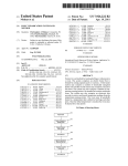
THREE VIEW DRAWING
Dimensions(mm)
Specifications
■ Displacement
■ Bore
■ Stroke
■ PracticalR.P.M.
■ Output
■ Weight
■ Silencer
26.23 cc(1.60cu.in.)
33.6 mm(1.323in)
29.6 mm(1.165in)
1,800~9,000 r.p.m.
3.7 ps / 8,500r.p.m.
945g (33.3oz.)
E-5010 (300g 10.6oz)
65
30
22
2-M5X0.8
64
22
80
96.7
50.5
UNF3/8-24
115.5
51.5
74
120.6
22
123.2
4-φ5.2
O.S. GENUINE PARTS & ACCESSORIES
■ O.S.GLOW PLUG
No.8
■ RADIAL MOTOR MOUNT ■ BOOSTER TERMINAL KIT
(72200130)
(71920000)
(71608001)
TYPE F
(71615009)
■ NON-BUBBLE
■ BOOSTER CABLE SET ■ PROPELLER LOCKNUT
(72200110)
SET FOR TRUTURN SPINNER
WEIGHT
3/8"-M5(S)
(71531000)
(29310110)
■ LOCK WASHER
(10sets)
■ SUPER FILTER (L)
(72403050)
■ LONG SOCKET WRENCH
WITH PLUG GRIP
(71521000)
M5 (55500004)
23
MEMO
24
UALITY PRECISION & PERF
ORM
AN
NC
E
UN
ES
ED Q
CE
L
UAL
EQ
TAB
L IS H
IN G T H E
STA N D A R D S O F
EXCE
LLE
6-15 3-Chome Imagawa Higashisumiyoshi-ku
Osaka 546-0003, Japan TEL. (06) 6702-0225
FAX. (06) 6704-2722
URL : http://www.os-engines.co.jp
C Copyright 2001 by O.S.Engines Mfg. Co., Ltd. All rights reserved. Printed in Japan.
040100