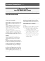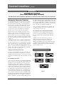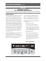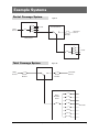
1
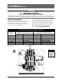
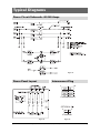
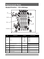
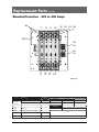
e
GE Zenith Controls
ZTX Series Automatic Transfer Switches
40-400 Amps
72 R -10 0 0
9/05
Operation and Maintenance Manual
Authorized Service
For GE parts and service, call: 773 299-6600
Table of Contents
Page
Introduction . . . . . . . . . . . . . . . . . . . . . . . . . . . . . . .1ii
Installation . . . . . . . . . . . . . . . . . . . . . . . . . . . . . . . . .11
Equipment Inspection and Storage . . . . . . . . .11
Final Equipment Inspection . . . . . . . . . . . . . . .11
Mounting . . . . . . . . . . . . . . . . . . . . . . . . . . . . . .11
Power Connections . . . . . . . . . . . . . . . . . . . . . .12
Engine Start Control Connections . . . . . . . . .13
Exerciser Option . . . . . . . . . . . . . . . . . . . . . . . .14
Functional Test . . . . . . . . . . . . . . . . . . . . . . . . .15
Jumper Positions . . . . . . . . . . . . . . . . . . . . . . . . .6
Control Interface . . . . . . . . . . . . . . . . . . . . . . . . . . .17
Indicator LED’s . . . . . . . . . . . . . . . . . . . . . . . . .17
Pushbuttons . . . . . . . . . . . . . . . . . . . . . . . . . . . .17
Using the Keypad Controls . . . . . . . . . . . . . . . .18
Automatic Generator Exerciser . . . . . . . . . . . .19
In-Phase Monitor Operation . . . . . . . . . . . . .110
Page
Example Systems . . . . . . . . . . . . . . . . . . . . . . . . . . . .11
Partial Coverage Systems . . . . . . . . . . . . . . . . .11
Total Coverage Systems . . . . . . . . . . . . . . . . . . .11
Typical Diagrams . . . . . . . . . . . . . . . . . . . . . . . . . . . .12
Power Circuit Schematic . . . . . . . . . . . . . . . . . .12
Power Panel Layout . . . . . . . . . . . . . . . . . . . . . .12
Interconnect Plug . . . . . . . . . . . . . . . . . . . . . . .12
Replacement Parts . . . . . . . . . . . . . . . . . . . . . . . . . .13
Standard Transition 40-200 Amps . . . . . . . . . .13
Standard Transition 225-400 Amps . . . . . . . . .14
Troubleshooting . . . . . . . . . . . . . . . . . . . . . . . . . . . .15
Introduction
GE Zenith Transfer Switches are used to provide a continuous source of power for lighting and other critical loads by automatically transferring from source 1 power to source 2 power in the event that source 1 voltage falls below preset limits.
Voltage sensing and system control is performed via a state-of-the-art microcontroller located on the cabinet door.
It is designed to give highly accurate control of the transfer switch system.
All GE Zenith transfer switches are designed for use on emergency or standby systems, and are rated for total system or
motor loads. Transfer switches are UL Listed under Standard 1008 and CSA Certified under Standard C22.2 No. 178 and
IEC Listed under Standard 947.
NOTES: A protective device such as a molded case circuit breaker or fused
disconnect switch MUST be installed on both sources of incoming
power for circuit protection and as a disconnection device.
All references made within this manual about the term “S1” or
“Source 1” relate to a Normal Power Source. All references made
about the term “S2” or “Source 2” relate to an Emergency
or Alternative Power Source.
Installation
DANGER
HAZARDOUS VOLTAGE
(Can Cause Severe Injury or Death)
Turn OFF all power before installation, adjustment, or removal of transfer switch or any of its components.
The safe operation of your switch is GE Zenith’s focus.
The proper storage, installation, operation and maintenance will help increase the life of the switch.
CAUTION
Due to hazardous voltage and current, GE Zenith recommends that a GE Zenith Certified technician or a
qualified electrician must perform the
installation and maintenance of the switch.
2.
3.
4.
Verify that all cabled connections are correct.
Check engine start connections and verify
the correct connection of all control wires.
Check the lug torque values of the power
connections.
NOTE:
5.
Make sure that all covers and barriers are
installed and properly fastened.
NOTE:
Equipment Inspection
and Storage
Once you have received the transfer switch, inspect
it for any damage. This includes damage to the enclosure, power panel, control panel and wiring harness. If
any damage is found or suspected, file a claim as soon as
possible with the carrier and notify the nearest GE Zenith
representative.
Before installation, it is necessary to store the transfer
switch in a clean dry place, protected from dirt and
water. Provide ample air circulation and heat, if
necessary, to prevent condensation.
Storage
Temperature
-30°C to
+75°C
(-22°F to
+167°F)
Operating
Temperature
(Ambient):
-20°C to +65°C
(-4°F to +149°F)
Humidity
5% to 95%
(non-condensing)
Prior to energizing the transfer switch:
1. Remove any debris incurred, with a vacuum,
due to shipment or installation.
WARNING
Do not use a blower since debris may
become lodged in the electrical and
mechanical components and cause damage.
■ GE Zenith Controls
Power panels ship from GE Zenith
in the Normal Position.
Each GE Zenith transfer switch is factory wired and
tested. A complete information package is furnished
with each switch which includes:
a. Sequence of operation.
b. Description and operation of
all accessories supplied.
c. Power panel connection diagram
and schematic.
d. Description and identification of
all customer field connections.
Installation of GE Zenith transfer switches includes:
a. Mounting the transfer switch cabinet.
b. Connection of all Normal, Emergency,
and Load cables or bus bars.
c. Connection of external control
circuits as required.
Mounting
Enough room should be allowed to open the cabinet doors
fully for inspection and servicing of the switch per NEC and
local codes.
NOTE:
Final Equipment Inspection
Lug torque values are specified
in the power panel manual.
When lifting the switch using a spreader bar,
height H must be equal to half of distance D.
CAUTION
Before drilling conduit entry holes or any
accessory mounting holes, cover and protect
the switch and control panel to prevent dirt
and metal fragments from entering the
mechanical and electrical components.
Failure to do so may result in
damage and malfunction of the switch.
ZTX Operation and Maintenance Manual (72R-1000)
1■
Installation
(cont’d)
DANGER
HAZARDOUS VOLTAGE
(Can Cause Severe Injury or Death)
Turn OFF all power before installation, adjustment, or removal of transfer switch or any of its components.
Connect the Normal, Emergency, and Load conductors
to the clearly marked terminals on the transfer switch.
Remove surface oxides from cables by cleaning with a
wire brush. Verify that all connections are correct before
tightening the lugs. All cable lug connections must be
tightened to the proper torque values as shown in Table 2.
Power Connections
GE Zenith transfer switches are supplied with UL listed
solderless screw type terminals as standard for the
Normal, Emergency and Load power connections.
Table 1 lists the number and sizes of cable lugs supplied
as standard for each switch amp rating.
NOTE:
Do not run cables or wiring behind
front-connected transfer switches.
Screw Type Terminals for External Power Connections
Switch Size
(Amps)
Fully Rated Neutral Bar (When Required)
Utility, Generator and Load Terminals
Cable Per Pole
Range of Wire Sizes
No. of Cables
Range of Wire Sizes
40
1
#8 to 3/0 AWG
3
#8 to 1/0 AWG
80
1
#8 to 3/0 AWG
3
#8 to 1/0 AWG
100
1
#8 to 3/0 AWG
3
#8 to 1/0 AWG
150
1
#8 to 3/0 AWG
3
#8 AWG to 300 MCM
200, 225, 250*
1
#6 AWG to 250 MCM
3
#6 AWG to 300 MCM
300, 400
1
#4 AWG to 600 MCM
3
#4 AWG to 300 MCM
Table 1
LOAD
TERMINALS
* IEC Rating Only
UTILITY
TERMINALS
T1
T2
T3
Tip!
OPTIONAL
TION
A4 CONTACT
N1
N2
N3
BR
OPERATES
ERAT WHEN IN
UTILITY
ILITY POSITION
Install
load
cables
first.
JP
SWITCH
POSITION
INDICATOR
N
E1
E2
E3
OPTIONAL
TION
A3 CONTACT
GENERATOR
TERMINALS
T = Load
N = Utility
OPERATES
ERAT WHEN IN
GENERATOR
NERA
POSITION
E = Generator
Figure 1 - Power Panel
■2
ZTX Operation and Maintenance Manual (72R-1000)
GE Zenith Controls ■
Installation
(cont’d)
DANGER
HAZARDOUS VOLTAGE
(Can Cause Severe Injury or Death)
Turn OFF all power before installation, adjustment, or removal of transfer switch or any of its components.
Control Connections
Note:
N = Utility Position
E = Generator Position
Connecting Engine Start may cause Generator to
start. Before connecting, turn Generator OFF.
With the Generator breaker open and the Generator
control switch off, install the Generator start connections.
Figure 4
JP
Manual operation is possible for maintenance purposes only.
Manual operation of the switch can be checked before it
is operated electrically.
Battery
Connection
With all power off, insert a Phillips screwdriver or equivalent
size tool into the manual operator socket and operate
the transfer switch between the Utility and Generator
positions. The transfer switch should operate smoothly
without binding. Return the switch to the Utility position,
remove the screwdriver.
Figure 2
The engine-start terminals are clearly identified by a
label on the microcontroller backplate. In the case of
manual transfer switches, or in other applications not
requiring the microprocessor, clearly marked terminal
blocks are provided in the upper left corner of the control
panel for the engine start control wires.
Terminals for field connections to the A3 Emergency
auxiliary contacts and the A4 Normal auxiliary contacts
are also provided. These terminals are clearly marked
and appear on the side of the power panel. On 400 amp
metal frame units these terminals appear on the bracket
above the operator handle.
g
GE Zenith Controls
VOLTS AMPS -
SYSTEM VOLTS:
Socket Size
Across Flats
Torque
Lb. - In.
Lb. - Ft.
1/8
45
4
5/32
100
8
3/16
120
10
7/32
150
12
1/4
200
17
5/16
275
23
3/8
375
31
1/2
500
42
9/16
600
50
Table 2
SERIAL NUMBER:
RATING:
Tightening Torque for Lugs
HZ PHASE -
MODEL NUMBER:
Figure 3
■ GE Zenith Controls
ZTX Operation and Maintenance Manual (72R-1000)
3■
Installation
(cont’d)
DANGER
HAZARDOUS VOLTAGE
(Can Cause Severe Injury or Death)
Turn OFF all power before installation, adjustment, or removal of transfer switch or any of its components.
ATTENTION!
This applies only to the switches with the RM4-CAT
exerciser option:
Only after ATS installation, connect a commercial-grade
alkaline 9V battery to the MX60 controller via the harness connected to the controller. The battery should be
placed in the holder installed just above the controller.
The battery is used to maintain the exerciser function in
the event of power outage. The battery should be
replaced at least once a year. If the battery is not
installed and/or replaced as recommended, an
exerciser set from the front panel will lose its settings
during power outages and the exerciser will not work.
Note: Battery life if reduced if neither source is available. Typical battery life when both sources are
unavailable is 21 days.
Should the battery connection become disconnected
in shipping, take the controller cover off and plug the
harness into the receptacle in the top right corner of
the MX controller as shown in figure 2 and 5. Reinstall
the cover and connect the battery.
Battery and Holder
Battery Harness
MX60 Controller
(Under Cover)
Figure 5
■4
ZTX Operation and Maintenance Manual (72R-1000)
GE Zenith Controls ■
Installation
(cont’d)
DANGER
HAZARDOUS VOLTAGE
(Can Cause Severe Injury or Death)
Turn OFF all power before installation, adjustment, or removal of transfer switch or any of its components.
Functional Test
Functional testing of the automatic transfer switch
(ATS) is described in this section. Before proceeding,
read and understand all instructions and review the
operation of all accessories provided.
To begin the test, close the Utility source circuit breaker.
Referring to Figure 7, the controller will illuminate the
Utility Available LED when proper voltage is sensed. If
the ATS mechanism is set on S1, the S1 position LED
will also light.. Verify the phase to phase voltages at the
Utility line terminals.
Next, close the Generator source breaker and start the
engine generator. The S2 (Generator) Available LED
will illuminate when proper voltage and frequency levels
are sensed. After both sources have been verified, shut
down the engine generator, and put the generator’s start
control in the automatic position. Complete the visual
inspection of the transfer switch, and replace the cabinet
cover (or close the cabinet door).
Simulate a utility outage by opening the S1 Utility side
breaker. The delay to engine start timer (P) begins its
timing cycle. After the P timer has completed its timing
cycle, the engine start contacts close to start the generator.
When generator voltage and frequency reach the preset
restore points (see Table 4) the S2 Available LED illuminates. Simultaneously, the delay to generator timer (W)
begins its timing cycle. When the W time delay is completed the ATS will transfer to Generator, the S1 position
LED goes off, and the S2 position LED illuminates.
Reclose the Utility breaker to retransfer to utility. The
delay to utility timer (T) begins its timing cycle (Table
3). When the T timer has completed its timing cycle, the
ATS will transfer. The optional S2 position LEDs go off,
and the S1 position LED illuminates. The delay engine
stop timer (U) begins its timing cycle. The generator
runs unloaded for the duration of the U timing cycle.
When the timer completes its timing cycle, the generator
will stop. The S2 Available LED goes off.
ATS Timing Cycle
Action
P Timer
P - 5 sec.
W Timer
W - 20 sec.
T Timer
T - 5 min.
U Timer
U - 5 min.
S1 Fail or
Test or
Exerciser
Time Delay
S2 Start
Time Delay
S2 Stable
Time Delay
S1 Stable
Time Delay
S2 Stop
Retransfer to S1
Engine Cool-Down
Transfer to S2
S1 returns or Test/Exerciser Ends
Table 3
Preset Settings
Utility
Generator
S1 Fail Voltage
80% Nominal Line Voltage
S2 Fail Voltage
S1 Restore
90% Nominal Line Voltage
S2 Restore Voltage
S1 Fail Frequency
80%
S2 Fail Frequency
S1 Restore Frequency
90%
S2 Restore Frequency
Timers
P Timer
P - 5 sec.
W Timer
W - 20 sec.
80% Nominal Line Voltage
90% Nominal Line Voltage
90%
95%
T Timer
T - 5 min.
U Timer
U - 5 min.
Table 4
■ GE Zenith Controls
ZTX Operation and Maintenance Manual (72R-1000)
5■
Installation
(cont’d)
DANGER
HAZARDOUS VOLTAGE
(Can Cause Severe Injury or Death)
Turn OFF all power before installation, adjustment, or removal of transfer switch or any of its components.
System Voltage Settings
Voltage / Frequency Selection Jumper Settings
ZTX controller boards are preconfigured to the system
voltages specified at the time of order. Exact system voltages are normally set at the factory, however, depending on the actual application and system nominal voltage, ZTX control boards are capable of being adjusted
slightly, to meet different source characteristics for
voltage as well as frequency. (See Table 5)
Figure 6 (on right) shows the variations each of the 3
basic types of controllers can be adjusted to within its
nominal voltage range. Position Jumpers JP1 and JP2,
as needed for voltage. Position JP3 for frequency.
As with any other Jumper setting, always remove power
completely from the controller before making changes.
240/480
120/380
JP1
JP1
JP2
JP2
A
B
208/416
JP1
JP1
JP2
JP2
A
Type 2
120V
JP1 JP2
B
B
-
208 - 240VAC
JP1 JP2
208 A
B
220 B
A
240 A
A
B
220/440
B
50Hz
A
B
A
B
60Hz
JP3
JP3
A
B
Note: Do not change voltage Jumper positions
without consulting service or technical support.
Arbitrarily changing voltage jumpers can adversely
affect ATS operation.
Type 1
A
Figure 6
Type 3
380 - 416VAC
JP1 JP2
380 B
B
416 A
B
-
Type 4
440 - 480VAC
JP1 JP2
440 B
A
480 A
A
-
Frequency
50 Hz
60 Hz
-
JP3
A
B
Table 5
■6
ZTX Operation and Maintenance Manual (72R-1000)
GE Zenith Controls ■
Control Interface
DANGER
HAZARDOUS VOLTAGE
(Can Cause Severe Injury or Death)
Turn OFF all power before installation, adjustment, or removal of transfer switch or any of its components.
Indicator LEDs
A
S1 (Utility) Available Green LED.
When on, indicates source is acceptable.
B
S1 (Utility) Position Green LED.
When on, indicates ATS is connected to Utility
C
S2 (Generator) Available Red LED.
When on, indicates source is acceptable.
D
S2 (Generator) Position Red LED.
When on, indicates ATS is connected to Generator.
E
Timing/In-phase Amber LED.
When blinking, indicates the ATS is timing a Delay
When on steady, indicates the ATS is waiting for both
sources to synchronize with each other.
C
D
E
A
B
Figure 7
F
G
■ GE Zenith Controls
H
I
Pushbuttons
F
TEST - Pressed and held for 1 second Simulates
a power outage, starts the Generator and
transfers the ATS to S2.
G
EXER SET - Sets an Automatic Exerciser
H
BYPASS TIMER - Pressed while E is blinking
bypasses any remaining countdown Timer
I
CANCEL - Depending on the current state of ATS
operation, ends specific functions or indications
ZTX Operation and Maintenance Manual (72R-1000)
7■
Control Interface
(cont’d)
DANGER
HAZARDOUS VOLTAGE
(Can Cause Severe Injury or Death)
Turn OFF all power before installation, adjustment, or removal of transfer switch or any of its components.
Using the Keypad Controls
TEST KEY
TIMER BYPASS
The TEST KEY initiates a transfer sequence to S2 and
holds the ATS in that mode until either the CANCEL
key is pressed or, a situation arises to cause the ATS to
go back to S1(ie, S2 actually fails).
This key is used to bypass (truncate), any of the running
timers shown in Table 3. Whenever the Timing/
Inphase LED is blinking, pressing the TIMER BYPASS
will end that particular delay and cause the ATS controller to immediately jump to the next sequence step.
In order to perform a TEST, the ATS must be on S1 and
S1 must qualify as a "good source" by being above the
FAIL thresholds for both Voltage and Frequency (see
Table 2).
Once the TEST KEY is pressed for at least 1 Sec, the
ATS will begin the Timer Sequence (see figure 5),
attempt to start S2 generator source, and if S2
qualifies as a "good source", transfer the load to S2.
(There is no P-Time in a test)
The TEST key is typically used to perform a system
operational or maintenance test or, to purposely cause
and hold the Load off of S1. If during the TEST, S2
fails and S1 is available, the TEST will be cancelled and
the Load will be immediately retransferred to S1.
EXER SET
Whenever it is required to have a regular test
performed automatically on a repeating basis, the
Automatic Exerciser function can be setup using
this key.
Note: The BYPASS key cannot be used to truncate an
In-phase transfer sequence, or the P-Timer.
CANCEL
The CANCEL key performs 3 different cancel actions
depending on the ATS current state of operation:
1. If the ATS is currently performing a TEST,
the CANCEL key will cancel the test.
2. If an Automatic Exerciser has been set, pressing and holding the CANCEL key for 10 Sec.
will cancel (and remove), the set exercise
3. If after in-phase monitor has passed 1 minute,
waiting for sources to synchronize, will cause
transfer immediatly (which may result in an
out-of-phase transfer).
Depending on the jumper settings shown in Figure 8,
the ATS can be programmed to perform a repeating 7,
14, 21 or 28 day exercise at a particular time of day.
To initiate an Automatic Exercise, the EXER SET key
is pressed and held for at least 1 Sec. at the desired
exercise time. The ATS will begin the Timer Sequence,
attempt to start S2 generator source and if S2 qualifies
as a good source, transfer the Load to S2 for the duration of the Generator Run-Time. After the Generator
Run-time has expired, the timing sequence will restart
and the Load will be transferred back to S1, after Ttime, ending by running the U-time and finally ending
the call for S2.
■8
ZTX Operation and Maintenance Manual (72R-1000)
GE Zenith Controls ■
Control Interface
(cont’d)
DANGER
HAZARDOUS VOLTAGE
(Can Cause Severe Injury or Death)
Turn OFF all power before installation, adjustment, or removal of transfer switch or any of its components.
Automatic Generator Exerciser
The ZTX automatic generator Exerciser can perform a
pre-scheduled repeating test of the generator and/or
the ATS mechanism depending on which jumpers are
selected on the controller board. Additionally, the ATS
can be preset to perform the exercise every 7, 14, 21
or 28 days. Regardless of which interval is selected, all
exercisers have a preset run-duration of 10 minutes.
Selection of the exerciser interval is through three
jumpers located on the controller board as shown in
Figure 6. The Exerciser comes from the factory preset
at 28 days and is not active. To change the exerciser
interval, remove power from the controller completely,
and move the jumpers at positions jp4 and jp5 to match
the selected repeat-cycle from the configurations shown
in Figure 7.
Selecting Exerciser with or without Load Transfer
The Exerciser function can be programmed to perform
either a Load-transfer or a non-Load transfer. Selecting
either is done by changing the Jumper JP6 as shown in
Figure 8. To change between a Load-transfer or no-Load
transfer, remove power from the controller completely
and move the jumper at position JP6.
Note: pressing the CANCEL key in the middle of an
scheduled event does not cancel a set Exerciser, but
only cancels the current event.
To completely clear an already-set Exerciser
A set Exerciser can be completely cleared out of
memory by pressing and holding the CANCEL key
for at least 10 Seconds causing the blink indication
to stop.
If S2 fails to meet the criteria for a good source,
during an Exercise attempt, the Controller will
continue to hold the P-contacts closed for the
duration of the Runtime timer then wait for the next
scheduled exercise. If S2 fails during an Exercise, the
Controller will abort that exercise and wait till then
next scheduled exercise.
Automatic Exerciser Jumper Settings
Setting and Canceling an Exerciser
In order to set an automatic Exerciser, choose the exerciser interval and whether a Load-transfer or no-Load
transfer is desired as stated above. An exercise can only
be set if S1 is available and the ATS (and Load), is on S1
source.
7 Day
14 Day
JP4
JP4
JP5
JP5
A
B
A
JP4
At the exact time desired, press and hold the EXER SET
key for at least 1 second. The ATS will immediately start
an initial exercise by attempting to start the generator,
running through the Timers (figure 3) and will either
only start the generator, or, will start the generator and
transfer the Load from S1 to S2, for the time duration
of the exerciser interval, 10 minutes. Once the Exercise
is completed, the ATS will continue the timing sequence
and retransfer the Load back to S1, cool down the generator and terminate until the next scheduled interval
time. Any time an Exerciser has been established and is
scheduled, the S2 Available and S2 position LEDs quickly blink approximately every 4 seconds as a reminder.
However, if S2 source becomes available during the time
B
28 Day
21 Day
To establish an Exerciser
■ GE Zenith Controls
the ATS is waiting for the next impending exercise, the
ATS will not show a blinking indication but instead will
show the S2 Available LED as solidly on to indicate the
true condition of S2. Any Exercise event can be prematurely canceled by pressing the CANCEL key.
JP4
JP5
JP5
A
B
A
JP6
B
No Load
JP6
Load
A
B
Figure 8
ZTX Operation and Maintenance Manual (72R-1000)
9■
Control Interface
(cont’d)
DANGER
HAZARDOUS VOLTAGE
(Can Cause Severe Injury or Death)
Turn OFF all power before installation, adjustment, or removal of transfer switch or any of its components.
In-Phase Monitor
ZTX ATS senses when the sources are as far out as 2 Hz
or as close as .01Hz in frequency differential of each
other and transfers the load to and from either source
in-phase. If turned on, R50 In-Phase monitor tracks the
frequency of both the Utility and Generator sources
allowing a smooth, synchronous transfer of the load,
which is especially beneficial where conveyors, pumps
and other motor loads are involved. ZTX indicates it is
waiting for the sources to synchronize by holding the
Timer/In-Phase LED on. When both sources have synchronized, the ATS will transfer the Load (within 20° of
each other, if sources are within 2Hz differential), and
the Timer/In-Phase LED will turn off. If the sources fail
to synchronize, after 1 minute, the controller will blink
the Timer/In-Phase LED once, alerting the operator
that the In-Phase monitor function can be bypassed by
pressing the CANCEL key, causing an immediate transfer (see Cancel Key function). If the CANCEL key is
not pressed, the ZTX will continue to wait for an inPhase condition to occur.
In the case of both sources coming from the same
source, or, one configured as WYE and the other as
DELTA, the frequency difference is fixed at the same
frequency or fixed but 30 degrees out of phase.
In those cases, In-Phase Monitor can be turned off.
In-Phase Monitor is turned on as default from the
factory. To turn In-Phase Monitor OFF or ON, take
the following steps:
In a typical ATS application, one source is on the utility
and one source is a backup system such as a gas or
diesel generator. Because sources have a slight
frequency difference, sources come in and out of phase.
If ZTX In-Phase Monitor is on, The ZTX ATS Controller
monitors both sources and transfers the Load at the
ideal time to minimize back-EMF conditions.
Turn In-Phase Monitor OFF:
1. Remove all power, (both S1 and S2) from
the controller. Wait at least 20 seconds.
2. From the keypad, hold both the BYPASS and
CANCEL keys down while energizing either
source. If In-Phase Monitor was on, the Timer
/ In-phase LED will flash once for 1 second,
then go out. The In-Phase Monitor is now off.
Turn In-Phase Monitor ON:
1. Remove all power, (both S1 and S2) from
the controller. Wait at least 20 seconds.
2. From the keypad, hold both the BYPASS and
CANCEL keys down while energizing either
source. If In-Phase Monitor was off, the
Timer/In-Phase LED will light and remain lit
until the keys are released. The In-Phase
Monitor is now on.
Timer / In-phase LED
Figure 9
■ 10
ZTX Operation and Maintenance Manual (72R-1000)
GE Zenith Controls ■
Example Systems
Partial Coverage System
Loads
Figure 9
Transfer Switch
Utility
Source
Circuit
Breaker
Generator
Source
Utility Panel
Loads
Distribution Panel
Total Coverage System
Figure 10
Transfer Switch
Utility
Source
Circuit
Breaker
Circuit
Breaker
Generator
Source
Main
Breaker
Panel
All Loads
■ GE Zenith Controls
ZTX Operation and Maintenance Manual (72R-1000)
11 ■
Typical Diagrams
Power Circuit Schematic 40-240 Amps
Figure 11
Power Panel Layout
Interconnect Plug
5
1
CCN
SN
SCOM
SE
E2
N1
N2
CCE
E1
10
6
OPTIONAL 3
4
2
Figure 12
■ 12
ZTX Operation and Maintenance Manual (72R-1000)
N2 E3
N3 E2
3
1
Figure 13
GE Zenith Controls ■
Replacement Parts
Standard Transition — 40 to 200 Amps
BR
SN
A4
CN/CE
SP+L
SE
A3
SCN/SCE
Figure 14
TAG
CN/CE
DESCRIPTION
Solenoid
Solenoid Plunger and Link
VOLTAGE
120
208
220
240
380/416
440/480
ALL
40 TO 200 AMPS
K-2207
K-2208
K-2208
K-2228
K-2212
K-2209
57P-1030
SCN/SCE
Coil Cutout Switch
120-480V
L-3078
SCN/SCE
Coil Cutout Switch
600V
L-4027
Rectifier
ALL
PS-5076
BR
A3/A4
Auxiliary Contacts
L-3078
Table 7
■ GE Zenith Controls
ZTX Operation and Maintenance Manual (72R-1000)
13 ■
Replacement Parts
(cont’d)
Standard Transition - 225 to 400 Amps
BR
T1
T2
T3
TN
N1 N2 N3 NN
CN/CE
SN
A4
SE
A3
E1
E2
E3
EN
Figure 15
Tag
N 1,2,3 N
E 1,2,3 N
T 1,2,3 N
Recommended
as Spares
Description
Cable Connection Lug
Wire Size
Stock Numbers by Amperage
225, 250*
260, 300*
400
S-2701
S-2701
S-2701
#6-250 MCM
#4-600 MCM
#4-600 MCM
Coil Volts
CN/CE
Solenoid
SN/SE
Position Sense Limit Switch
A3/A4
Auxiliary Contacts
BR
Rectifier
*
208/220/240
K-2246B
L-3078
*
PS-5076
Table 8
■ 14
ZTX Operation and Maintenance Manual (72R-1000)
GE Zenith Controls ■
Troubleshooting
DANGER
HAZARDOUS VOLTAGE
(Can Cause Severe Injury or Death)
Turn OFF all power before installation, adjustment, or removal of transfer switch or any of its components.
Service must be performed by qualified personnel.
Symptom
Possible Cause
Corrective Action
S1 or S2 Available LED not lit
Sources either fully or partially unacceptable
S1 or S2 breakers open
Check for under voltage
Check for missing phase (s)
Check for under frequency
ATS will not retransfer Load
back to Utility
T - Timer has not expired
Automatic Exerciser is in process
S1 Utility fully or partially unacceptable
ATS does not transfer Load to S2
(generator)
S2 Generator fully or partially unacceptable
Motor loads on system creating enough backEMF to keep missing phase from falling below
Fail setpoint.
Set motor-saver to dropout below
ATS Fail setpoint
S2 Generator will not start
X1 or X2 not connected
Check Generator Start wiring
S2 Generator will not shut down
U - Timer not expired
Automatic Exerciser in process
Wait for U timer to expire
All LEDs off
Keypad connector unplugged at Controller
Both source breakers open
ATS will not transfer in-phase
In-Phase monitor not on
Frequency difference between S1 and
S2 greater than 2Hz.
Turn on In-Phase monitor
Adjust Generator governor to hold
freqency closer to Utility
ATS will not retain a
Set Automatic Exerciser
Battery dead or missing
Replace battery with a fresh industrial
grade Alkaline battery
Timer/In-Phase LED constantly on
Both sources locked in frequency or one
source greater than 20° out of phase
Turn In-Phase monitor off
S1 and S2 LEDs Blinking
Phase Rotation Mis-match between sources
Rewire sources to be same rotation
S1 Position LED Blinking
SN limit switch bad or intermittent
Check connection or SN limit switch
S2 Position LED Blinking
SE Limit switch bad or intermittent
Check connection or SE limit switch
Both S1 and S2 Positioin
LEDs Blinking
Solenoid bad or disconnected
ATS contactor in mid-position
Requires CANCEL key to clear check Solenoid
Requires CANCEL key to clear Check both limit switches
Table 9
■ GE Zenith Controls
ZTX Operation and Maintenance Manual (72R-1000)
15 ■
g
GE Zenith Controls
A Product of GE Consumer & Industrial
General Electric Company
830 West 40 th Street, Chicago, IL 60609 USA
773 299-6600, Fax: 773 247-7805
www.geelectrical.com