1
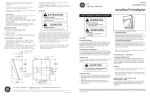
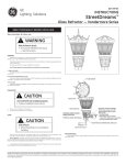
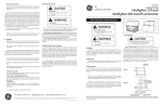
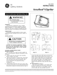
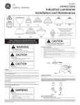
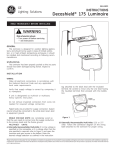
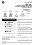
g
GEH-5861E
GE
Lighting Solutions
VB5
INSTRUCTIONS
Industrial Luminaires
Installation and Maintenance
UW5
UT5
GL5
OB5, OB6
FP5
UG5, UG6
LARGE BALLAST HOUSING FOR SOME
OPTIONS
(See GE Lighting Systems Product
Catalog for details)
PG5
UM5
MB5
CAUTION
READ THOROUGHLY BEFORE INSTALLING
SAVE THESE INSTRUCTIONS FOR FUTURE USE
WARNING
Risk of electric shock
• Turn power off before servicing
CAUTION
Risk of injury
• Wear safety glasses and gloves during
installation and servicing
CAUTION
UG6
Unit will fall if not installed properly
• Follow installation instructions
CONDUIT MOUNTING
1.
2.
3.
4.
5.
6.
7.
8.
Fasten the mounting plate (minimum of five full turns) to a 3/4-inch conduit by threading the
mounting plate onto the conduit. See Figure 1.
Tighten the set screw to lock the mounting plate to the conduit.
Loosen the set screw on the top corner of the ballast housing.
Loosen the wiring box door screws on the ballast housing to allow the wiring box door to pivot.
Pivot the wiring box door 180 degrees to allow the mounting plate room to slide onto the ballast
housing.
Slide mounting plate onto ballast housing, making sure that the upper rim of the ballast housing
slides into the rails of the mounting plate. (Figure 2)
Tighten the set screw on the top corner of the ballast housing so that the mounting plate cannot
back out.
After wiring is complete, pivot the wiring box door back into the original position and tighten the
two wiring box door screws.
Figure 1
Risk of burn
• Do not touch operating luminaire
GENERAL
This luminaire is designed for indoor applications only, and should be installed and maintained according
to these instructions.
NOTE: The maximum fixture ambient temperature rating is the LESSER of the ratings indicated on the
ballast and optical assemblies.
All luminaire refractors and lenses made of acrylics or polycarbonates will yellow over time with exposure
to heat and ultraviolet (UV) light. The rate of yellowing is determined by the specific material, any additives
and coatings, the operating temperature, and the amount of UV exposure. Yellowing can reduce the light
output and lower the impact resistance of acrylic or polycarbonate opticals.
In no case should the maximum lamp wattage listed for the luminaire be exceeded. Contact the factory
for more information.
UNPACKING
This luminaire has been properly packed to avoid damage during transit. Inspect the luminaire to confirm
there is no damage. Do not install a damaged luminaire or damaged luminaire components.
Figure 2
FLEXIBLE MOUNTING
If flexible mounting accessories (hook or loop) are supplied separately, follow the instructions above for
conduit mounting .
CAUTION: If this instruction is not followed damage to the mounting parts can occur causing the
fixture to fall. When using hook or loop fixture mounting, do not apply luminaire weight when the
mating parts are as shown in Figure 3. Do not apply any twisting action to the hook and loop assembly.
When properly installed the hook and loop assembly is shown in Figure 4.
NOTE: The luminaire is supplied with a hanger hub and locking nut which are threaded together, and
are included in the ballast housing carton.
INSTALLATION
WARNING
Risk of fire
• Keep combustible materials away from lens
• Use lamps specified on the “luminaire fitting”
nameplate
• Maintain a minimum of 3 feet clearance
below the luminaire
Figure 3
Figure 4
WET LOCATION OPTION
(Water tight seal bwteen conduit and hub)
1.
Fasten hanger hub securely (minimum of five full turns) to 3/4-inch conduit by threading locking nut
and hanger hub assembly onto conduit. See Figure 5.
These instructions do not purport to cover all details or variations in equipment nor to provide for every possible contingency to be met in connection with installation, operation or maintenance.
Should further information be desired or should particular problems arise which are not covered sufficiently for the purchaser’s purposes, the matter should be referred to GE Lighting Solutions.
2.
3.
4.
5.
6.
Orient any one of arrows on bottom of hanger hub in direction that you wish a flat side of ballast
housing to face.
Tighten set screw to lock hanger hub to conduit.
Loosen locking nut until free to move up conduit.
Twist supply leads. Slip ballast housing onto hanger hub and position housing approximately 30
degrees counter-clockwise from final desired position.
Rotate housing clockwise until seated on hanger hub with wiring box facing in desired direction.
NOTE: Check for proper seating by trying to rotate assembly counter-clockwise while it is supported
by the hanger hub.
7.
Hand tighten locking nut against ballast housing. When installing units provided with a gasket between
hanger-hub and locking nut, be sure to tighten nut securely so that gasket is compressed fully
around pipe nipple to prevent entrance of moisture.
KEEPER
NUT
LAMP BODY TIGHTNESS
The lamp should be inserted and tightened to the NEMA-EEI specified torque of 35 inch-pounds. Tightening
must be sufficient to fully depress and load center contact of socket. This is best achieved by very firmly
tightening to insure application of sufficient torque.
If the unit has a SAFETY LIGHT option, insert the quartz lamp in its socket making sure to wipe any
fingerprints off lamp.
NOTE: Use of lubricants on lamp bases or sockets can cause rapid lamp failure and voids your fixture
warranty.
SAFETY LIGHT OPTION
The SAFETY LIGHT option (Auxiliary Quartz Lamp) , if used, must be rated for 120V and from 100 to 250 Watts.
When power is applied, the Auxiliary Quartz Lamp, (if used) will immediately turn on. As the HID Lamp
strikes and warms up, the Auxiliary Quartz Lamp will automatically shut down.
During normal HID Lamp operation, if the power is interrupted, the HID Lamp will extinguish and the
Auxiliary Quartz lamp will turn on, until the HID Lamp restarts. After the HID Lamp restarts, the Auxiliary
Quartz Lamp will automatically shut down.
Should the HID Lamp fail to start, the Auxiliary Quartz Lamp will provide back up lighting. If the HID Lamp
completely fails to start, replace the HID Lamp.
SAFETY CHAINS
HANGER
HUB
CAUTION
Figure 5
Unit will fall if Safety Chain is not installed
properly
• Safety chains must be installed as
described below.
WIRING
Make all electrical connections in accordance with the National Electrical Code and any applicable local
code requirements.
Verify that supply voltage is correct by comparing it to the ballast assembly nameplate.
If unit is designated as multivolt or multiwatt, follow the specific instructions.
Single Voltage Units: Installer needs to connect supply and ground conductors to the fixture’s primary
leads and ground wire. These wires are located on the small wiring harness that contains the 9-pin plug.
After these wires are connected, the 9-pin plug wired in the fixture needs to be mated with the
9-pin plug wired to the supply conductors if not already connected.
Multivolt Units: (Connectable for 120, 208, 240, 277 volts)
CAUTION: Do not remove insulated connectors from wires not needed for required voltage connection.
Select the proper wires from the connection diagram on the unit. Connect the specified wires by using
crimp connectors on the wires. These crimp connectors are sized for 14-16 AWG. For other AWG sizes
remove the crimp connector(s) provided and use other appropriate approved connector(s).
Safety chains and attachment accessories are available from the factory as an optional accessory for both
ballast and optical assemblies. Safety chains should be attached with minimum slack. Luminaire safety
chains must be installed in a manner which prevents the luminaire from falling more than six (6) inches
before it is caught by chain.
To install a ballast safety chain, insert the “S’’ hook through the hole in the ballast housing and crimp shut.
To install optical safety chain, insert “S” hook through a link in ballast safety chain and crimp shut. Use the
snap hook to attach to the clip or hole on the optical as shown in Figure 8.
MAINTENANCE AND CLEANING
NOTE: Attach ground conductor to the green ground wire supplied with the fixture.
The interior and exterior surfaces of open opticals and the exterior surface of lens doors on enclosed
opticals require periodic cleaning to maintain light levels. The required frequency of cleaning depends on
the ambient dirt level and the minimum light level which is acceptable to the user. Optical surfaces should
be cleaned by washing in a solution of warm water and a mild, non-abrasive household detergent, rinsed
with clean water, and wiped dry with a soft
9-Pin Plug Removal: Removal of the 9-pin plug does not hinder the electrical performance of the luminaire,
but its removal does negate the GELS diagnostics meter compatibility.
non-abrasive towel. Should an enclosed optical assembly become dirty on the inside, clean the reflector
and the lens door in above noted manner. Inspect and replace any damaged gaskets.
Multi-Watt Units: See procedure under Multivolt above.
FINAL ASSEMBLY
OPTICAL ASSEMBLY/MOUNTING—
OB5, OB6, UG5, UG6, UW5, UM5, UT5, GL5, VB5, MB5
1.
1a.
2.
3.
Secure the reflector to bottom of the ballast housing as shown in Figure 6. Installation is aided by
key hole slots in the reflector. On VB5 and MB5 units with safety chains, orient the reflector so that
the ballast and reflector safety chain holes are on the same side.
On VB5 units push the reflector mounting bracket thru the reflector opening and slide it over the
socket brackets all the way. On 400 watt Metal Halide units the top (first) hole of the mounting
bracket will snap over the socket bracket screws. On all others, the bottom (second) hole will snap
over the bracket screws. See Figure 7.
For additional assembly instructions, refer to the instruction sheet that came in the small box with
the metal reflector and mounting bracket.
Refer to LAMP INSTALLATION and screw lamp into socket.
For enclosed units, close the door and secure it properly in place by latching first latch opposite
hinge, followed by other latches.
NOTE: If VB5 unit has a SAFETY LIGHT option, clip the quartz socket over the socket bracket leg and
reflector bracket leg in a horizontal position as shown in Figure 7.
KEYHOLE SLOTS
SOCKET
REFLECTOR
LOCKING TABS
Figure 6
QUARTZ
SOCKET
Figure 7
HOLE IN HOUSING
LAMP INSTALLATION/REPLACEMENT
CAUTION
CRIMP “S” HOOK TO
LINK IN BALLAST
SAFETY CHAIN
BALLAST SAFETY CHAIN
OPTICAL SAFETY CHAIN
Risk of burn
• Allow lamp/fixture to cool before handling
LAMPS
The light output of a luminaire is dependent on the age of lamp. In applications where light level is critical
it may be desirable to replace lamps before they burn out. Lamp manufacturer’s can provide data showing
how lamp light output decreases with use and recommended replacement intervals.
Figure 8
ATTACH SNAP HOOK
TO CLIP OR HOLE
ON OPTICAL
CAUTION: Use only lamps specified on nameplate. Observe lamp manufacturer’s recommendations
and restrictions on lamp operation, ballast type, burning position, handling, and disposal.
g
GE Lighting Solutions • 1-888-MY-GE-LED • www.gelightingsolutions.com
1-88 8 - 6 9 - 4 3 -5 3 3
GE Lighting Solutions is a subsidiary of the General Electric Company. Evolve and other trademarks belong to GE Lighting Solutions. The GE brand and logo are trademarks of the General Electric Company.
© 2011 GE Lighting Solutions. Information provided is subject to change without notice. All values are design or typical values when measured under laboratory conditions.
35-201578-8P (8/05)