1
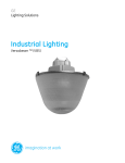
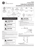
g
GEH-5956B
GE
Lighting Solutions
INSTRUCTIONS
NUVATION™
Electronically Ballasted Industrial Luminaires
With Electromechanical Sliding Optical Disconnect
Installation and Maintenance
VERSABEAM PROTECTED BY
U.S. PATENT NUMBER 5,416,684
FGE
DGE
OGE
READ THOROUGHLY BEFORE INSTALLING
SAVE THESE INSTRUCTIONS FOR FUTURE USE
WARNING
Risk of electric shock
• Turn power off before servicing
CAUTION
Risk of injury
• Wear safety glasses and gloves
during installation and servicing
CAUTION
Risk of burn
• Do not touch operating luminaire
GENERAL
This luminaire is designed for indoor applications only, and should
be installed and maintained according to these instructions.
The Nuvation™ ballast is designed to operate 250W,300W, 320W,
350W and 400W pulse start and ceramic metal halide lamps with
line voltages from 208-277 volts.
See nameplate for more information.
Any part damaged or broken during or after assembly or installation
should be replaced.
LME
VSE
NOTE: The maximum fixture ambient temperature rating is
the LESSER of the ratings indicated on the ballast and optical
assemblies.
NOTICE: There are no user serviceable parts inside this ballast
housing and there should not be a need to access the inside of
the ballast housing.
Minimum clearance of 3 feet must be maintained below
luminaire.
If the luminaire you ordered has a polycarbonate/acrylic refractor,
please pay particular attention to the following statement:
All -articles made from polycarbonates/acrylics, including
polycarbonate/acrylic resin, will yellow with time. The rate of
yellowing is determined by the specific material, any additives
and coatings, as well as the optical temperature and exposure
to Ultraviolet (UV) light.
This yellowing can reduce the light output and impact resistance
of products made from polycarbonate/acrylic resin. In no case
should the maximum lamp age, wattage rating, or ambient
rating listed for the luminaire be exceeded. Contact factory for
more information.
UNPACKING
This luminaire has been properly packed to avoid damage
during transit. Inspect the luminaire to confirm there is no
damage. Do not install a damaged luminaire or damaged
luminaire components.
NOTE: The Nuvation luminaire is supplied with a Slide-On
Through Wire Box which may be included in the carton ready
to install.
These instructions do not purport to cover all details or variations in equipment nor to provide for every possible contingency to be met in connection with installation, operation or
maintenance. Should further information be desired or should particular problems arise which are not covered sufficiently for the purchaser’s purposes, the matter should be referred
to GE Lighting Solutions.
INSTALLATION
THREADED
BOSS
WARNING
WIRE BOX SLIDE
MOUNTING
BRACKET
WIRING BOX
Risk of fire
• Keep combustible materials away
from lens
• Use lamps specified on the
“luminaire fitting” nameplate
• Maintain a minimum of 3 feet
clearance below the luminaire
CAUTION
Figure 3
Unit will fall if not installed properly
• Follow installation instructions
• Attach ONLY by threaded Boss
• Do not use Knockout Holes for
mounting.
CONDUIT MOUNTING
1. Remove the Wire Box End Cover by removing the two (2)
screws as shown in Figure 1.
CONDUIT (NOT SUPPLIED)
SET
THREADED
BOSS
WIRING BOX
END COVER
WIRING BOX
Figure 1
COVER SCREWS
1.A. For Nuvation™ with Dimming Option, remove both wiring box
doors (Figure 2) for electrical connections and box removal.
3.
Slide the Wiring Box onto the Mounting Bracket, which is
preassembled on to the Upper Housing as shown in
Figure 3.
NOTE: The Ballast Housing is not fully secure until the wire box
End Covers are reattached!
4.
5.
Connect the supply wires from mains to the Black and White
supply leads. Connect the Green Earth Ground Lead. Adhere
to the requirements defined the WIRING section below.
Replace the Wire Box End Covers. Insert and securely
retighten the End Cover Screws as shown in Figure 2.
The Ballast Housing is now secure.
FLEXIBLE MOUNTING
If flexible mounting accessories (hook or loop) are supplied
separately, thread the shaft into hanger hub/locking nut
assembly and follow the instructions above for conduit mounting.
CAUTION: If this instruction is not followed damage to the
mounting parts can occur causing the fixture to fall. When
using hook or loop fixture mounting, do not apply luminaire
weight when the mating parts are as shown in Figure 4. Do not
apply any twisting action to the hook and loop assembly. When
properly installed the hook and loop assembly is as shown in
Figure 5.
Figure 4
Figure 2
2.
Thread the Wiring Box onto the conduit. Secure the conduit
with the set screw provided. Ensure that the Wire Box cannot
turn on the conduit once Set Screw has been tightened.
Figure 5
WET LOCATION OPTION
When installing in a wet location, it is important to properly install
the Conduit with an appropriate water sealing material. The GE
Lighting Systems wet location wiring box and a GE Lighting
Systems wet location optical must be used.
WIRING
Make all electrical connections in accordance with the -National
Electrical Code and any applicable local code requirements.
Verify that the supply voltage is correct by comparing it to the
ballast’s “luminaire fitting” nameplate.
CAUTION
Risk of Electrical Damage
• DO NOT MISMATCH wattage setting
and Metal Halide HID Lamp wattage.
• Verify that the circuit wiring and
circuit breakers are rated for the total
circuit load.
The Luminaire wattage is preset at the factory. Please contact the
factory for instructions and a retrofit kit if a different wattage is
required.
The Nuvation ballast is rated for use with a supply voltage
between 208V and 277V with +/- 10% line voltage tolerance, 50/
60 Hz, and will automatically sense voltage within the specified
range.
The wire colors for the input lines in the wiring box are:
Black Color = Primary Phase
White Color = Neutral or Secondary
Phase
Green Color = Fixture - Earth Ground
Violet Color = (+) 0-10VDC Dimming
Gray Color = (-) 0VDC Dimming
All
Nuvation
Models
Dimming
Nuvation
DIMMING FEATURE / INSTRUCTIONS
The Nuvation ™ meets the lamp manufacturers requirements of
starting/operating the lamp at high wattage for at least 15
minutes before any dimming control can happen.
For continuous operation (24 hr/day) the Nuvation will
automatically go into a full power mode once a day for at least 15
minutes as required by lamp specifications.
WIRING NOTES: Polarity of the dimming control leads
(VIOLET + and GRAY -) must be maintained.
DIMMING CONTROL
Dimming control is accomplished by connection to the
VIOLET + AND GRAY –
Wires in the wiring box (Figure 2). See Diagram A for wiring
schematic.
POLARITY MUST BE PROPERLY APPLIED
(VIOLET + To control +) AND (GRAY – To control -)
Shorting (example with a switch) the violet and gray wires will
cause the Nuvation to operate at low wattage, removing the short
will cause the lamp to operate at full wattage.
External control systems can be used to operate the bi-level
function.
A zero (0) to ten (10) volt DC power supply can control the bi-level
operation.
This can be either to continuously adjustment lamp wattage 50%
to 100 %.
Or one step 50% to 100%.
DC Control Voltage
Output Level
0V
50%
+5V
75%
Diagram A
Added Features of the GELS NUVATION™
• Automatic lamp shut off if the lamp fails to start within 90
minutes
• After a power shut off the NUVATION must be switched off and
then back on (cycle time 1 to 2 seconds).
• Automatic lamp shut off for end of life high voltage lamps
FINAL ASSEMBLY
LIGHT DISTRIBUTION ADJUSTMENT: FGE, DGE, OGE
The Optical Assembly is provided with an adjustable Socket
Holder for changing spacing criteria. Position is preset at factory
to meet specified spacing criteria. If it is necessary to adjust
Socket, consult photometric tables given in the catalog. Loosen
3 Clip Screws to allow Socket Holder to rotate freely. Desired
position is selected by aligning step designation with clips. Rotate
Clips back to their original position and retighten screws.
OPTICAL ASSEMBLY/MOUNTING
FGE, DGE, LME, OGE, VSE
NOTE: Wet Location units are provided with a sponge rubber
Gasket (in bag attached to ballast housing) that must be slipped
over electrical plug prongs of optical assembly before final
assembly.
1. (Figure 6) Slide Reflector to bottom of Ballast Housing.
1a. On VSE units with Safety Chains, orient the reflector
so that the Ballast Housing and Reflector Safety
Chain Attachment Holes are on the same side.
1b. On VSE units push the Reflector Mounting Bracket
thru the reflector opening and slide it over the Socket
Brackets all the way. On 400 watt Metal Halide units
the top (first) hole of the Mounting Bracket will snap
over the Socket Bracket screws. On all others, the
bottom (second) hole will snap over the bracket
screws (Figure 7). For additional assembly instructions, refer to the instruction sheet that came
in the small box with the metal reflector and
-mounting bracket.
SOCKET
+10V
100%
POLARITY MUST BE PROPERLY APPLIED
(VIOLET + To control +) AND (GRAY – To control -)
A resistor or potentiometer (pot) can also be used to continuously
adjust lamp wattage by connecting to the VIOLET + and GRAY –
wires. The resistor or potentiometer should be in the 0 – 50K ohm
range. The voltage output from the VIOLET + and GRAY – wires will
be in the 0-10 volt range and current will be less than one (1)
milliamp.
LOCKING
TABS
Figure 6
Figure 7
SOCKET
QUARTZ
SOCKET
LOCKING
TABS
Figure 8
NOTE: If VSE unit has a safety light option, clip Quartz Socket
over Socket Bracket leg and reflector bracket leg in a horizontal
position (see Figure 8).
2.
3.
Refer to LAMP INSTALLATION and screw lamp into socket.
NOTE: In case of unit LME, lamp installation is accomplished
through Access Door in Lens by using a relamp stick.
(For enclosed units only) Close Door and secure properly in
place by latching first latch opposite hinge, followed by other
latches.
NOTE: The OGE has wing nuts in place of latches.
SAFETY CHAINS
LAMPS
The light output of a luminaire is also dependent on the age of the
Lamp. In applications where the light level is critical, it may be
desirable to replace lamps before they burn out. The lamp
manufacturer can provide data showing how the lamp light
output decreases with use.
CAUTION: Use only lamps specified on nameplate. Observe lamp
manufacturer’s recommendations as restrictions on lamp
operation, ballast type, burning position, handling and disposal.
Lamp Tightness – Mogul Base Lamp: The Lamp should be
tightened to the NEMA-EEI specified torque of 35 inch-pounds,
which is best achieved by very firmly tightening to insure application
of sufficient torque. Tightening must be sufficient to fully depress
and load the Center Contact of the socket.
CAUTION
Unit will fall if Safety Chain is not
installed properly
• Safety chains must be installed as
described below.
CAUTION: When used, safety chains must be carefully installed
as outlined below.
Safety chains and attachment accessories are available from the
factor as an optional accessory for both ballast and optical
assemblies. Safety chains should be attached with minimum
slack. Luminaire safety chains must be installed in a manner that
prevents the luminaire from falling more than six (6) inches before
it is caught by chain.
To install ballast safety chain, insert the “S” hooks though the hole
in the ballast housing and crimp shut.
To install an optical safety chain, insert the “S” hook through a link
in ballast safety chain and crimp shut. Use the snap hook to attach
to the clip or hole on the optical as shown in Figure 9.
Auxiliary Quartz Lamp: if the unit has this option, inset the quartz
lamp in its socket making sure to wipe any fingerprints off lamp
following the quartz lamp instructions.
NOTE: Use of lubricants on lamp bases or sockets can cause
rapid lamp failure and voids your fixture warranty
The Auxiliary Quartz Lamp (if used) must be rated for 120V and
from 100 to 250 Watts.
When power is applied, the Auxiliary Quartz Lamp, (if used) will
immediately turn on. As the HID Lamp strikes and warms up, the
Auxiliary Quartz Lamp will automatically shut down.
During normal HID Lamp operation, if the power is interrupted, the
HID Lamp will extinguish and the Auxiliary Quartz lamp will turn
on, until the HID Lamp restarts. After the HID Lamp restarts, the
Auxiliary Quartz Lamp will automatically shut down.
Should the HID Lamp fail to start, the Auxiliary Quartz Lamp will
provide back up lighting. If the HID Lamp completely fails to start,
replace the HID Lamp.
MAINTENANCE
1.
2.
HOLE IN HOUSING
BALLAST SAFETY CHAIN
CRIMP “S” HOOK TO
LINK IN BALLAST
SAFETY CHAIN
OPTICAL SAFETY
CHAIN
ATTACH SNAP HOOK
TO CLIP OR HOLE
ON OPTICAL
Figure 9
LAMP/INSTALLATION/REPLACEMENT
There are no user serviceable parts within the ballast housing.
The ballast will automatically shut down if the lamp voltage
is too high. This is to reduce the chance of Non Passive Failure
of the lamp. The ballast will restart when the power to the unit
is turned off and then back on.
3. The ballast will automatically shut down if the HID lamp will
not start within a 90 minute time period. The ballast will
restart when the power to the unit is turned off and then back
on.
It will occasionally be necessary to clean outside of refractor to
maintain light level. Frequency of cleaning will depend on ambient
dirt level and minimum light level which is acceptable to user.
Lens Door (if enclosed) should be washed in a solution of warm
water and any mild, nonabrasive household detergent, rinsed
with clean water and wiped dry. Should optical assembly become
dirty on inside, wipe reflector and clean lens door in above
manner, and replace any damaged gaskets.
CAUTION
Risk of burn
• Allow lamp/fixture to cool before
handling
g
GE Lighting Solutions • 1-888-MY-GE-LED • www.gelightingsolutions.com
1-88 8 - 6 9 - 4 3 -5 3 3
GE Lighting Solutions is a subsidiary of the General Electric Company. Evolve and other trademarks belong to GE Lighting Solutions. The GE brand and logo are trademarks of the General Electric Company.
© 2011 GE Lighting Solutions. Information provided is subject to change without notice. All values are design or typical values when measured under laboratory conditions.
35-201578-149 (8/07)