1
g
GE
Lighting Solutions
GEH-3926D
INSTRUCTIONS
Tunnel Guard™ Luminaire
Installation and Maintenance
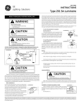
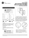
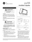
READ THOROUGHLY BEFORE INSTALLING
WARNING
Risk of electric shock
• Turn power off before servicing
– see instructions
CAUTION
Risk of burn
• Do not touch operating luminaire
GENERAL
This luminaire is designed for tunnel lighting
applications, and should not be used in high ambient
temperature enclosures; it should be installed and
maintained according to the following recommendations.
CAUTION: Hold the luminaire firmly to keep it from
swinging when the latches are released.
Reverse the above steps for mounting the luminaire.
B. RECESSED MOUNTING: (Figure 2)
UNPACKING
This luminaire has been properly packed so that no parts
should have been damaged during transit. Inspect to
confirm.
INSTALLATION
MOUNTING:
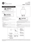
CAUTION
Unit will fall if not installed properly
• Follow installation instructions
Two types of mounting are available for this luminaire:
A. SURFACE MOUNTING: (Figure 1)
Figure 2
Install luminaire (A) using the slots provided on the
mounting plate (B).
NOTE: Orient the luminaire with the traffic flow
according to the direction label provided on its
surface.
WIRING
Figure 1
Install luminaire (A) using the slots provided on the
mounting plate (B).
NOTE: Orient the luminaire with the traffic flow
according to the direction label provided on its
surface.
NOTE: To remove the luminaire from the mounting
plate release the two (2) large latches (C). Gently
swing the luminaire away from the plate, then lift it
out from the quick-release hinges (D).
Figure 3
MAKE ALL ELECTRICAL CONNECTIONS IN
ACCORDANCE WITH THE NATIONAL ELECTRICAL
CODE AND US COAST GUARD REQUIREMENTS CFR
46 SECTION 110 THROUGH 113.
These instructions do not purport to cover all details or variations in equipment nor to provide for every possible contingency to be met in connection with installation, operation or
maintenance. Should further information be desired or should particular problems arise which are not covered sufficiently for the purchaser’s purposes, the matter should be referred
to GE Lighting Solutions.
Verify that supply voltage is correct by comparing it
to nameplate.
NOTE: On units with power cord attached:
a) If the lamp is already installed go directly to
Step 6.
b) If the lamp is not yet installed, do Step 1, then go
to Step 5.
1. Open the door by unlatching the door latches (E).
CAUTION: Hold door firmly to keep from swinging
open when the latches are released.
2. Feed the power cable through the cable entrance hole
(F), rubber bushing (G), and compression plate (H).
Secure in place by tightening the screws provided.
Use only lamps specified on nameplate. Observe lamp
manufacturer’s recommendations and restrictions on
lamp operation, particularly ballast type, burning
position, etc.
Lamp Tightness – Mogul Base Lamp: The lamp should
be securely inserted to the NEMA-EEI specified torque of
35 inch-pounds, which is best achieved by very firmly
tightening to insure application of sufficient torque.
Tightening must be sufficient to fully depress and load the
center contact of the socket.
6. (SURFACE MOUNTING UNITS only.) Use one of the
two cable clips (M) to retain and control the power cable
slack. (See Figure 1).
MAINTENANCE
NOTE: The optical door is opened by releasing the
optical door latches (E) and swinging the door
open.
NOTE: Cable strain relief and sealing are provided
by the compression plate and rubber bushing
supplied for 9/16'’ O.D. cable. Three conductor,
AWG No. 14 cable is recommended. Stranded cable
is required for shipboard applications.
CAUTION: Hold door firmly to keep it from
swinging open when the latches are released.
3. Route the cable through the plastic cable clip (J).
4. Connect ground lead to the ground screw (K) and make
electrical connections to the luminaire pigtail leads (L)
or the terminal board.
Do not remove insulated connectors from wires not
needed for required voltage connection.
When changing voltage on reconnectable units,
move only the lead with the insulated connector.
IF SINGLE VOLTAGE:
All single voltage ballasts are pre-wired such that user
need only connect the supply conductors.
IF MULTIVOLT: (120/208/240/277 volts)
Connect the ballast lead with the insulated terminal to
the desired voltage terminal as indicated on the ballast
terminal nameplate.
IF MULTIWATT:
Multiwatt ballasts are available in various combinations
of wattage. See wiring instructions on wiring tag inside
the luminaire.
5. Install the lamp and close and latch the door.
CAUTION
Risk of burn
• Allow lamp/fixture to cool before
handling
g
NOTE: The door may be removed by opening
approximately 190 degrees, lifting up slightly and
sliding (sideways) the door off the hinge pins on
the housing.
To remove the ballast tray (Figure 3):
1. Disconnect the wiring connector plug (N).
2. Release the latch (P) and slide the tray to the opposite
side so that the support tabs disengage and release the
tray from the luminaire.
CAUTION: When the tabs disengage, the tray is no
longer supported by the luminaire. Firmly grip the
handles (R) to prevent the tray from falling.
It will occasionally be necessary to clean the outside of
the door glass to maintain the light level. Frequency of
cleaning will depend on the ambient dirt level and
the minimum light level which is acceptable to the user.
The door glass should be washed in a solution of warm
water and any mild, non-abrasive household detergent,
rinsed with clean water and wiped dry. Should the optical
assembly become dirty on the inside, wipe the reflector and
clean the door glass in the above manner. Replace any
damaged gasket.
The light output of a luminaire is also dependent on the
age of the lamp. In applications where the light level is
critical it may be desirable to replace lamps before they
burn out. The lamp manufacturer can provide data
showing how the lamp light output decreases with use.
GE Lighting Solutions • 1-888-MY-GE-LED • www.gelightingsolutions.com
1-88 8 - 6 9 - 4 3 -5 3 3
GE Lighting Solutions is a subsidiary of the General Electric Company. Evolve and other trademarks belong to GE Lighting Solutions. The GE brand and logo are trademarks of the General Electric Company.
© 2011 GE Lighting Solutions. Information provided is subject to change without notice. All values are design or typical values when measured under laboratory conditions.
35-201578-K3 (3/06)