1
g
GEH-3908F
GE
Lighting Solutions
READ THOROUGHLY BEFORE INSTALLING
INSTRUCTIONS
Town and Country,
Salem™ Luminaires
Salem
Town and Country
WARNING
Risk of electric shock
• Turn power off before servicing
– see instructions
GENERAL
This luminaire is designed for outdoor lighting service,
and should not be used in areas of limited ventilation, or in
high ambient temperature enclosures. Best results will be
obtained if installed and maintained according to the
following recommendations.
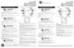
TRCR
TR1C and TR1R
T10C and T10R
UNPACKING
This luminaire has been properly packed so that no parts
should have been damaged during transit. Inspect to
confirm.
MOUNTING
CAUTION
Unit will fall if not installed properly
• Follow installation instructions
This luminaire is provided with means for mounting on
3.000'' max. outside diameter pole tops.
Feed the power supply leads through the slipfitter wire
access hole as the fixture is installed on the pole.
Orient canopy screw or latch toward street and level by
adjusting the three screws, and tighten.
(CAUTION: Tighten screws to 15 - 20 foot pounds
torque.)
WIRING
NOTE: Make all electrical connections in accordance
with the National Electrical Code and any applicable
local code requirements.
NOTE: Verify that supply voltage is correct by
comparing it to nameplate.
120/240 VOLT field RECONNECTABLE ballasts are
factory connected for 120 volt supply. For 240 volt operation, rewire per attached wiring tag.
Loosen the captive screw or release the latch which holds
down the canopy, tilt canopy back toward the house side.
Connect power supply leads to the luminaire leads provided
or to the optional terminal board.
NOTE: Connect ground lead to the green ground
screw on the housing or terminal block.
LAMP INSTALLATION – HID
CAUTION
Risk of burn
• Allow lamp/fixture to cool before
handling
NOTE: Use only lamps specified on nameplate.
Observe lamp manufacturer’s recommendations
and restrictions on lamp operation, particularly
ballast type, burning position, etc.
Damage may occur to the fixture if the lamp is inserted
while the power is on, or if the lamp is not tight in the
socket when the power is applied.
Lamp Tightness Mogul Base Lamp: The lamp should be
securely inserted to the NEMA-EEI specified torque of 35
inch-pounds, which is best achieved by very firmly tightening to insure application of sufficient torque. Tightening
must be sufficient to fully depress and load the center
contact of the socket.
These instructions do not purport to cover all details or variations in equipment nor to provide for every possible contingency to be met in connection with installation, operation or
maintenance. Should further information be desired or should particular problems arise which are not covered sufficiently for the purchaser’s purposes, the matter should be referred
to GE Lighting Solutions.
LAMP INSTALLATION –
INDUCTIVE TECHNOLOGY LAMP
PHOTOELECTRIC CONTROL
CAUTION
Risk of burn
• Allow lamp/fixture to cool before
handling
NOTE: Use only lamps specified on nameplate.
Observe lamp manufacturer’s recommendations
and restrictions on lamp operation, particularly
ballast type, burning position, etc.
Damage may occur to the fixture if the lamp is inserted
while the power is on.
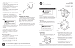
The inductively coupled electrodeless lamps are factory
supplied with the lamp installed. To replace the lamp,
remove the four screws holding the mounting brackets to
the reflector (Figure 1). Disconnect the lamp wiring
harness and attach the new lamp. Secure the new lamp with
the four screws through the mounting bracket and close the
fixture. Use one of the following lamps: OSI 26100 or
OSI 26101.
When a photoelectric control is used, the photoelectric
receptacle should be oriented so that the word “North’’ is
directed toward the true north direction. This can be easily
done by seating a photoelectric control into the receptacle,
lifting upward on the photoelectric control (which will lift
the photoelectric receptacle also), and rotating them
clockwise until the word “North’’ is directed toward the true
north direction. Lower the photoelectric control and
receptacle to firmly seat them into position. No tools are
required to make this orienting adjustment.
Alternatively, the photoelectric receptacle can be oriented before the photoelectric control is installed. This is
done by lifting up on the rim of the photoelectric receptacle
and rotating it until the word “North’’ is directed toward
the true north direction. Lower the photoelectric receptacle
to firmly seat it in this position. Install the photoelectric
control.
Because of the shielding of the cupola window by the
cupola top it may be necessary to adjust for an earlier turnon time of the photoelectric control.
ONE PIECE REFRACTOR REPLACEMENT
To remove a textured refractor on this luminaire, loosen
the canopy captive screw or latch and tilt back the canopy.
Remove the refractor assembly unit. To replace refractor
reverse this procedure.
FOUR PIECE REFRACTOR REPLACEMENT
To replace a prismatic refractor on this luminaire,
loosen the canopy captive screw or latch and tilt back the
canopy. Disconnect the photoelectric receptacle plug and
unclip the leads form the house side panel. Remove the
refractor panels as a unit. Release the defective panel from
the tongue and groove. To replace the assembly reverse this
procedure.
MAINTENANCE AND CLEANING
Figure 1
g
WARNING: MAKE CERTAIN POWER IS OFF
BEFORE ATTEMPTING ANY MAINTENANCE.
It will occasionally be necessary to clean the optical parts
in order to maintain the light level. Frequency of cleaning
will depend on the dirt level in the area and the minimum
light level which is acceptable. Wash with non-abrasive
soap, cleaner or detergent solutions and rinse with cool
water.
GE Lighting Solutions • 1-888-MY-GE-LED • www.gelightingsolutions.com
1-88 8 - 6 9 - 4 3 -5 3 3
GE Lighting Solutions is a subsidiary of the General Electric Company. Evolve and other trademarks belong to GE Lighting Solutions. The GE brand and logo are trademarks of the General Electric Company.
© 2011 GE Lighting Solutions. Information provided is subject to change without notice. All values are design or typical values when measured under laboratory conditions.
35-201578-E9 (8/01)