1
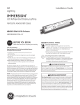
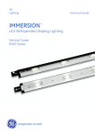
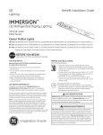
GE
OEM Installation Guide
Lighting
IMMERSION
TM
LED Refrigerated Display Lighting
Vertical Cases
RV60 Series
End Mullion Lights
48-inch: GELT604850EDR-SY/-SB (85743/85746), GELT604850EDL-SY/-SB (85744/85747), GELT604840EDR-SY/-SB (85749/85752),
GELT604840EDL-SY/-SB (85750/85753), GELT604835EDR-SY/-SB (85755/85758), GELT604835EDL-SY/-SB (85756/85759)
60-inch: GELT606050EDR-SY/-SB (85700/85703), GELT606050EDL-SY/-SB (85701/85704), GELT606040EDR-SY/-SB (85706/85709),
GELT606040EDL-SY/-SB (85707/85710), GELT606035EDR-SY/-SB (85712/85715), GELT606035EDL-SY/-SB (85713/85716)
67-inch: GELT606750EDR-SY/-SB (85720/85723), GELT606750EDL-SY/-SB (85721/85724), GELT606740EDR-SY/-SB (85726/85734),
GELT606740EDL-SY/-SB (85727/85735), GELT606735EDR-SY/-SB (85737/85740), GELT606735EDL-SY/-SB (85738/85741)
Description Code (Single Unit Product Number/10-Pack Product Number)
BEFORE YOU BEGIN
Read these instructions completely and carefully.
FOR YOUR SAFETY
Read and observe all CAUTIONS and WARNINGS shown
throughout these instructions.
• Installation to be performed by factory trained service personnel only.
• For use inside a commercial refrigeration case with packaged foods only.
• Use this unit only in the manner intended by the manufacturer. If you have any questions, contact the manufacturer.
• Before installing, servicing or cleaning unit, switch power off at the service panel and follow appropriate lock out/tag out safety procedures
This device complies with part 15 of the FCC Rules. Operation is
subject to the following two conditions: (1) This device may not cause
harmful interference, and (2) this device must accept any interference
received, including interference that may cause undesired operation.
NOTE: This equipment has been tested and found to comply with the
limits for a Class A digital device, pursuant to part 15 of the FCC Rules.
These limits are designed to provide reasonable protection against
harmful interference when the equipment is operated in a commercial
environment. This equipment generates, uses, and can radiate radio
frequency energy and, if not installed and used in accordance with
the instruction manual, may cause harmful interference to radio
communications. Operation of this equipment in a residential area
is likely to cause harmful interference in which case the user will be
required to correct the interference at his own expense.
PREPARE ELECTRICAL WIRING
Electrical Requirements
• The power supply must be supplied with 100-240 VAC,
50/60 Hz, and connected to an individual properly grounded
branch circuit, protected by a 15 or 20 ampere circuit breaker
or time delay fuse.
• Wiring must be 2 wire with ground and rated for 75°C (167°F).
• Do not overload driver, follow installation instructions for the
GEPS6000NCMUL-SY or GEPS6500NCMUL-SY.
• Ensure that all connection points are sealed for damp location
using the appropriate method per the NEC or local electrical code.
LED DRIVER COMPATIBILITY
This system is compatible with GEPS6000NCMUL-SY or
GEPS6500NCMUL-SY LED Driver. Please refer to the separate
LED driver installation guide for appropriate wiring connections.
CAUTION/ATTENTION
Risk of injury. While performing installations described, gloves, safety
glasses or goggles should be worn. / Risque de blessure. Lors de
l'exécution des installations décrites, des gants, des lunettes de sécurité
ou des lunettes de protection doivent être portées.
WARNING/AVERTISSEMENT
Risk of electrical shock. Disconnect power before servicing or
installing product. / Risque de choc électrique. Couper le courant
avant de réparer ou installer le produit.
imagination at work
Tools Required
Components Required
1
2
4
1
3
3
5
6
2
7
1 Wire stripper/cutter
1 LED light
2 Tape measure
3 Screwdriver
4 Cordless drill
2 LED driver
3 Wire cover
4
4 6-32 x 1/2" screws
5 Hammer
6 7/64-inch (2.8mm) drill bit
7 Center punch
WARNING/AVERTISSEMENT
Risk of fire or electric shock. Luminaire wiring and electrical parts may be damaged when drilling for installation of LED retrofit kit. Check for
enclosed wiring and components. / Risque de feu ou électrocution. Les pièces et câbles électriques risquent d’être endommagés lors du perçage
des trous pour l’installation du luminaire à DEL. Veuillez vérifier si des câbles et composantes se trouvent derrière la paroi avant de percer.
To prevent wiring damage or abrasion, do not expose wiring to edges of sheet metal or other sharp objects. / Pour éviter l'endommagement de
câblage ou l'abrasion, ne pas exposer le câblage aux bords de feuilles de métal ou d'autres objets tranchants.
1
A
Left End Shield
Prepare for Installation of
End LED Lights
1-3/32" (28 mm)
1-3/32" (28 mm)
Right End Shield
LED Driver Leads
2 1/8" (54 mm)
• Measure 1 3/32-inches (28 mm) from the edge of the mullion
nearest the door, and mark a vertical line near the top and
bottom of the frame mullion.
3/8" (10 mm)
• Prepare for the upper end of the End LED Light. Mark a
horizontal line a minimum 2 1/8-inches (54 mm) from the top
of the door opening, and another horizontal line 3/8-inches
(10 mm) below this line.
• Prepare for the lower end of the End LED Light.
— For 48-inch LED Lights mark a horizontal line
46 1/4" (1175mm) beneath the first line drawn for
the top Mounting Tab.
— For 60-inch LED Lights mark a horizontal line
58 3/32" (1476mm) beneath the first line drawn for
the top Mounting Tab.
— For 67-inch LED Lights, mark a horizontal line
65 15/32" (1663mm) beneath the first line drawn for
the top Mounting Tab.
Then mark another line 3/8-inches (10 mm) below this line.
• Center the center punch directly at the intersection of the
horizontal lines and the vertical line (top and bottom) and
establish a dimple.
• Use power drill and 7/64-inch (2.8 mm) drill bit to drill
holes at the intersection of the vertical center line and the
horizontal lines.
• Repeat these steps for the mullion on the other end of the case.
2
For 48-inch LED Lights:
46 1/4" (1175mm)
For 60-inch LED Lights:
58 3/32" (1476mm)
For 67-inch LED Lights:
65 15/32" (1663mm)
Center punch
at intersection
and drill a
7/64-inch (2.8 mm)
hole
End Mullion-Left
3/8" (10 mm)
End Mullion-Right
View from inside case looking out
1B
Wire
Wire
Identify End LED LightRight from Left
EDL
EDR
• Verify LEDs are directed towards the center
of the case before installing.
NOTE: Installing the LED Light on the wrong
side will result in very low light level inside the
refrigerated case.
View from inside case looking out
WARNING/AVERTISSEMENT
Risk of electrical shock. Only those open holes indicated in the photographs and/or drawings may be made or altered as a result of kit
installation. Do not leave any other open holes in an enclosure of wiring or electric components / Risque de choc électrique. Seuls les trous
ouverts indiqués dans les photos et / ou les dessins peuvent être faites ou modifiés à la suite du montage du kit. Ne pas laisser autres trous
ouverts dans l'enceinte du câblage électrique ou composants.
2
Install End LED Lights
• Place proper End LED Light against the face of the mullion near the two holes drilled at the top.
NOTE: Refer to proper End LED Light orientation depicted in Step 1B.
End LED Light
Power Leads
• Insert a #6-32 x 1/2-inch sheet metal screw into the slot of the Mounting Tab on the End LED Light, and into the first hole that was drilled in the end mullion.
• Use a screwdriver to start threading the screw into the
drilled hole.
• Repeat for the second screw, and for the bottom of the End
LED Light.
• Repeat these steps for the mullion on the other end of the case. Make sure the orientation is correct and proper LED Light is used.
• Refer to the manufacturing manual for door frame to ensure there are no components contained inside the mullion that could be drilled through. Use a #6 - 3/4-inch self-drilling screw to attach the End LED Light into one or two of the additional
mounting holes located near the center of the LED Light.
• Refer to wiring diagram on page 5. Connect the red and black
output wires from the LED Light to the red and black wires on the LED Driver using the twist lock splice wire connectors provided.
3
Mounting Tab
LED Driver
Output Leads
CAUTION/ATTENTION
Risk of injury. Do not overload LED Driver. Do not exceed limits shown in “Maximum LED Driver Loading” table below. Risque
de blessure. Ne pas surcharger l'alimentation. Ne pas exéder les limites de la table ci-dessous: “Charges maximales pour les
alimentations.”
LED Driver Configuration Options
Both 50-watt and 100-watt LED Drivers are available for a variety of case configurations.
Maximum LED Driver Loading
50W Driver
100W Driver
60-inch LED Lights
3 Center + 1 End
7 Center
67-inch LED Lights
3 Center
6 Center
48-inch LED Lights
4 Center
8 Center
(1 Center may be substituted by 2 End LED lights)
Parts Needed Per Case
6-Door
5-Door
4-Door
3-Door
2-Door
Center LED Lights
5
4
3
2
1
End LED Light Sets
1
1
1
1
1
Wire Covers
7
6
5
4
3
LED Drivers (60-inch LED Lights)
2
2
2
1
1
LED Drivers (67-inch LED Lights)
2
2
2
1
1
LED Drivers (48-inch LED Lights)
2
2
1
1
1
LED Drivers (60-inch LED Lights)
1
1
1
1
1
LED Drivers (67-inch LED Lights)
2
1
1
1
1
LED Drivers (48-inch LED Lights)
1
1
1
1
1
Using 50W LED Drivers
Using 100W LED Drivers
4
WARNING/AVERTISSEMENT
Risk of electrical shock. Ensure that all connection points are sealed for damp location using the appropriate method per
the NEC or local electrical code. Risque de choc électrique. S’assurer que les points de raccordements sont scellés pour
emplacement humide en employant une méthode permise par le NEC ou par le code électrique local.
Connection Configurations
Multiple LED Light’s electrical input should be in parallel connection to an LED driver’s output as shown by
the example wiring diagram below. Refer to “Maximum LED Driver Loading” table to determine maximum
number of LED lights per LED driver.
One End Set (Right and Left) &
One Center LED Light
Note: LED Lights are polarity insensitive
BR
BR
LEFT END LED LIGHT
C
B
R
LED DRIVER
W
CB
G
Driver Wire
Connector Cavities
BR
CENTER LED LIGHT
SWITCH
RIGHT END LED LIGHT
3
A
B
Gray
Purple
D
Occupancy Sensor
WHITE (NEUTRAL)
Terminal Block
(AC Source)
BLACK (LINE)
For information on A, B, C, D, see Steps 4, 5 and 6.
39-01-4030 (AC)
Cavity 1 - Line 1 (Black)
Cavity 2 - Earth Ground (Green)
Cavity 3 - Neutral or Line 2 (White)
39-01-4046 (DC)
Cavity 1 - Output DC (+) (Red)
Cavity 2 - Output DC (-) (Black)
Cavity 3 - Dimming (Purple)
Cavity 4 - Dimming (Gray)
4
Connect LED Driver - Output
• Make output (DC) connections using one of the two options below:
OPTION 1 – USING 4-WAY CONNECTOR
Connect the LED Driver output leads to the LED Light leads
using the appropriate mating connector (Molex P/N 3901-4046). Terminals installed should be crimped using
approved tooling and process per Molex specifications.
Ensure that the connector cavities are correctly populated
per the wire cavity table on page 5. A
OPTION 2 – USING TWIST-ON WIRE CONNECTORS
Remove the 4-way connector from the LED Driver by
cutting the wires near the connector and strip the output
leads. Using the appropriate wiring diagram on page 5,
connect the LED Driver output leads to the LED Light leads
using wire connectors or other connection method approved
for low temperature usage and stranded cable. A
For non-dimming applications, cap the unused wires with
5/32” (4mm) twist on wire connectors.
5
Connect LED Driver - Input
• Make input (AC) connections using one of the two options below:
• The LED Driver is required to be reliably bonded to the protective ground conductor. B
OPTION 1 - USING 2-WAY CONNECTOR
Attach the supplied green/yellow ground wire from the
LED Driver to a grounded metal portion of the door frame.
Connect the original Line and neutral wires (or Line 1 and
Line 2 wires for 240 nominal VAC) to the 3-way connector
for the LED Driver input wires using the appropriate mating
connector (Molex P/N 39-01-4030). Ensure that the
connector cavities are correctly populated per the
wire cavity table on p. 5. C
Connect Dimming Contacts – Output (Optional)
• To enable dimming operation, connect leads from occupancy sensor or control system (normally open contact) to the purple
and gray leads of the power supply. Other methods, such as using occupancy sensors to switch the LED driver on and off is not recommended and will void the product warranty.
• Make output (contact closure) connections using one of the two options below:
OPTION 1 - USING 4-WAY CONNECTOR
OPTION 2 – USING TWIST-ON WIRE CONNECTORS
Connect the LED Driver dimming output leads to the
occupancy sensor or control system using the appropriate
mating connector (Molex P/N 39-01-4046). Terminals installed
should be crimped using approved tooling and process per
Molex specifications. Ensure that the connector cavities are
correctly populated per the wire cavity table on page 5. D
Remove the 4-way connector from the LED Driver by
cutting the wires near the connector and strip the output
leads. Using the appropriate wiring diagram on page 5,
connect the LED Driver dimming output leads to the
occupancy sensor or control system using wire connectors
or other connection method approved for low temperature
usage and stranded cable. D
• The GEPS6000NCMUL-SY or GEPS6500NCMUL-SY LED Driver is capable of step dimming from 100% power to 20% power when used with a normally open contact closure occupancy sensor system.
• When using the GEPS6000NCMUL-SY or GEPS6500NCMUL-SY for dimming applications, the slider switch setting must be set to the right to disable the dimming feature and achieve 100% illumination.
DIMMING
SWITCH
6
OPTION 2 – USING TWIST-ON WIRE CONNECTOR
Attach the supplied green/yellow ground wire from the LED
Driver to a grounded metal portion of the door frame.
Remove the 3-way connector from the LED Driver by
cutting the wires near the connector and strip the input
wires. Using the appropriate wiring diagram on page 5,
connect the original Line and neutral wires (or Line 1 and
Line 2 wires for 240 nominal VAC) to the LED Driver leads
using twist lock wire connectors or other connection
method approved for low temperature usage and stranded
cable. Ensure that the connector cavities are correctly
populated per wire cavity table on page 5. C
Dimming
Dimming Enabled (20%)
Dimming Disabled (default)
6
DIMMING SWITCH
CAUTION/ATTENTION
Risk of electrical shock. Plastic cover is needed to protect electrical wires from tampering and accidental contact. / Risque de choc
électrique. Le couvercle en plastique est requis pour assurer une protection adéquate contre l'accès aux fils et les contacts accidentels.
7
Wire Cover
Attach Covers to End Cap
• Tuck wires underneath Wire Cover before placing it over the
End Cap and Mounting Tab.
M2.9x10 pan
head tapping
screw
• Attach Wire Cover to LED Light End Cap by installing a
M2.9x10 pan head tapping screw (provided) through the
hole in the End Cap and Mounting Tab using an installation
torque of 3 lbf-in.
NOTE: Tighten slowly until fully seated, do not over tighten or
strip the threads.
End Cap
• Repeat these steps for the mullion on the other end of the case.
CAUTION/ATTENTION
Risk of electrical shock. Plastic cover is needed to protect electrical wires from tampering and accidental contact. /
Risque de choc électrique. Le couvercle en plastique est requis pour assurer une protection adéquate contre l'accès aux
fils et les contacts accidentels.
Wire Cap
8
Removal Instructions
• Using a phillips screwdriver, remove screw and cover from wire end of LED Light and screw from opposite end of LED Light.
• Electrical connections can be removed to facilitate the
removal of the LED Light.
• Remove the #6-32 x 1/2 inch sheet metal screws that hold
the LED Light to the mullion. Make sure you support the
End LED Light with your free hand.
• Repeat these steps for the mullion on the other end of the case.
7
WARNING/AVERTISSEMENT
Risk of electrical shock. Disconnect power to LED Lights before any cleaning operation.
Risque de choc électrique. SDébranchez l'alimentation des éclairages à LED avant toute opération de nettoyage.
9
LED Refrigerated Display Lights – Cleaning Instructions
• The outer lens and the plastic housing should be cleaned
periodically with a mild liquid dish detergent.
• Do not wipe the lens with a soiled dish cloth or wet towel.
These may leave a residue that can damage the finish.
• Do not use chemical cleaners to clean the lens.
• Do not use scouring pads, powdered cleaners, bleach or
cleaners containing bleach because these products can
scratch and damage the finish.
• Keep the outside clean. Wipe with a clean cloth lightly
dampened with mild liquid dish detergent. Dry with a clean,
soft cloth.
This product is intended solely for the use of commercial refrigerated, display or
case lighting and is not intended for use in any other application.
GE Lighting Solutions • 1-888-MY-GE-LED
(1-888-69-43-533)
• www.gelighting.com
GE Lighting Solutions, LLC is a subsidiary of the General Electric Company. Immersion is a trademark of GE Lighting. The GE brand and logo are trademarks of the General Electric Company.
Information provided is subject to change without notice. All values are design or typical values when measured under laboratory conditions.
© 2013 GE 63540 121013