1
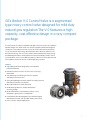
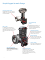
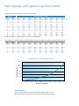
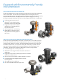
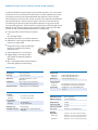
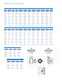
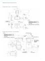
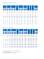
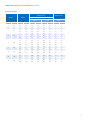
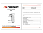
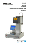
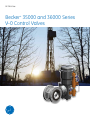
GE Oil & Gas
Becker* 35000 and 36000 Series
V-0 Control Valves
2 | Dresser
GE’s Becker V-0 Control Valve is a segmented
type rotary control valve designed for mild duty
natural gas regulation.The V-0 features a high
capacity, cost effective design in a very compact
package.
The 35000 Series V-0 valve incorporates flangeless end connections for installation
between flanges. The 36000 Series V-0 valve incorporates raised face flange end
connections in accordance with ISA S75.04. The 35000 Series valves are offered
in 150, 300, and 600 ANSI ratings and the 36000 Series valves are offered in 150
and 300 ANSI ratings. The V-0 Control valve utilizes the Becker RSD Rotary Spring
and Diaphragm actuators. When paired with GE environmentally friendly control
instrumentation, the V-0 is the ideal high capacity valve for mild duty pressure and
flow regulation, and on/off service in natural gas piping systems.
Features
■■
High capacity ball valve design allows low wide open
pressure differential
■■
Extended turndown in excess of 300:1 with v-notch segmented ball
■■
Soft seat design for bubble tight shutoff or stainless
steel seat for erosive process
■■
Spring and diaphragm actuators require low supply pressure
and reduced transient consumption
■■
Easy maintenance minimizes downtime
■■
Versatile design allows for simple field actuator
mounting change
■■
Becker ZERO BLEED* instrumentation reduces costly
atmospheric gas emissions in steady state
■■
Proven Becker VRP Valve Regulator Pilot and DNGP Digital
Natural Gas Positioner offer accurate steady-state control
■■
Use in control or ON/OFF applications
3
Simple Rugged Versatile Design
Flanged or Flangeless Design
Integral flange (150 and 300 Class) and
flangeless (150, 300, and 600 Class) end
connections available
Spring and Diaphragm
Actuator
High Turndown
The segmented ball design with the
v-notch characteristic offers high wideopen capacity and optimal low-end control
resulting in total turndown in excess of
300:1
Large diaphragm area requires low
supply pressure and low transient
consumption.Spring loaded fail safe
is easily field reversible
Simple Enclosed Housing
Enclosed actuator housing protects
linkage from the elements and is
safer for station personnel
Blowout-Proof Shaft
The shaft is designed so that it can
not blow out, even with the actuator
and packing follower removed
Position Indication
Visible rotary indicator allows quick
visual inspection of valve position
Soft or Metal Seat Design
Easily interchangeable soft seat
(standard) offering Class VI shutoff, or
stainless steel seat (optional) offering
Class IV shutoff
4
Splined Stem Connections
A durable and accurate involute spline
connects the stem to the ball and
torque arm. Unlike pins or keys, concentrated stresses are avoided to ensure long
trouble-free service
High Capacity with Optimal Low-End Control
Flanged Body Design (Available in Classes 150 and 300)
Valve Size
V-0 Control Valve (Degrees Open)
(in)
(mm)
10
20
30
40
50
60
70
80
90
1
25
0.2
1.2
2.9
5.2
8.2
12.1
17.3
25.6
55.0
1.5
40
0.4
2.7
6.5
11.9
18.8
27.5
39.4
58.1
125
2
50
0.5
3.7
8.8
16.1
25.5
37.4
53.5
79.0
170
3
80
1.3
9.4
22.9
41.8
66.0
96.8
138.6
205
440
4
100
2.2
15.9
38.5
70.3
111
163
233
344
740
6
150
3.8
26.9
65
119
188
275
394
581
1250
8
200
5.6
40
97
177
279
409
586
865
1860
10
250
9
64.9
157
287
453
664
951
1404
3020
12
300
13.2
95
229
418
660
968
1386
2046
4400
Flangeless Body Design (Available in Classes 150, 300 and 600)
Valve Size
V-0 Control Valve (Degrees Open)
(in)
(mm)
10
20
30
40
50
60
70
80
90
2
50
0.3
4.7
12.7
23.3
39.0
58.2
81.5
112
163
3
80
1.5
7.4
22.3
44.6
73.7
114
164
242
372
4
100
2.3
17.3
40.3
74.2
121
178
247
371
575
6
150
4.6
30.2
78.9
148
231
331
463
664
1160
8
200
5.7
47.8
120
225
354
512
749
1180
1770
Capacity Curve for 6” (150 mm) Flangeless V-0
1200
Flow Coefficient (Cv)
1000
800
600
400
200
0
0
10
20
30
40
50
60
70
80
90
Degrees Travel (Open)
High Rangeability
The V-0 Control Valve offers a modified equal percentage capacity curve
allowing optimal control at both the low end and high wide-open capacity
5
Equipped with Environmentally Friendly
Instrumentation
Pressure Control with VRP Valve Regulator Pilot
The Becker Model VRP-SB-CH Single-Acting Pilot provides pressure control when utilized with
the V-0 Control Valve. The VRP-SB-CH pilot measures process sensing pressure and
positions the single-acting V-0 actuator to maintain the pressure setpoint. The VRP-SB-CH pilot
may be utilized for pressure control applications with setpoints ranging from 1.0 psig
(6.9 kPa) to 1480 psig (10204 kPa). The VRP-SB-CH pilot features ZERO BLEED™ in steady state.
■■
Purely pneumatic pressure control
■■
ZERO BLEED™ technology eliminates
atmospheric emissions in steady state
■■
Design specifically suited for natural
gas production, midstream, distribution, and transmission
■■
Setpoint ranges from 1 to 1480 psig
■■
Rugged design is vibration resistant
and suitable for demanding pipeline
applications
Flow or Pressure Control with DNGP Digital Natural Gas Positioner
The Becker DNGP Digital Natural Gas Positioner is used with the V-0 control valve to provide
an accurate valve stem position that is proportional to the electronic command input signal
received from an electronic controller. The DNGP eliminates the need for an I/P transducer
and features ZERO BLEED™ consumption at steady state. Additionally, the DNGP features
easy, menu driven setup along with PC interfaced diagnostic and setup features. Most
importantly, the DNGP offers multiple fail safe modes to protect your gas pipeline.
■■ 4-20 mA analog and 12 or 24 VDC pulse input
■■
ZERO BLEED™ technology eliminates atmospheric emissions in
steady state
■■
Design specifically suited for natural gas production, midstream,
distribution, and transmission
■■
Explosion proof design may be installed in hazardous locations
■■
Illuminated display and navigational menus for easy
field configuration
■■
Split range control for multiple runs
■■
Push-button manual local positioning of valve
6
ON/OFF Over/Under-Pressure Protection with VRP-SB-GAP Controller
The Becker Model VRP-SB-GAP Single-Acting Controller provides on-off control when
utilized with the V-0 Control Valve. The VRP-SB-GAP controller measures the process
sensing pressure and closes the actuated valve upon pressure rising to the high
pressure setpoint. Conversely, VRP-SB-GAP controller will re-open the actuated valve
upon pressure falling to the low pressure setpoint. The action of the VRP-SB-GAP
controller may be reversed to open an actuated valve upon rising pressure while
closing on falling pressure. The VRP-SB-GAP controller may be utilized for gap control
applications with setpoints ranging from 1.0 psig (6.9 kPa) to 1480 psig (10204 kPa).
The VRP-SB-GAP controller features ZERO BLEED™ in steady state.
■■ Purely pneumatic over/under-pressure protection
for on/off applications
■■
Automatic reset when trip condition removed
■■
ZERO BLEED™ technology eliminates atmospheric
emissions in steady state
■■
Design specifically suited for natural gas
production, midstream, distribution,
and transmission
■■
Setpoint ranges from 1 to 1480 psig
■■
Rugged design is vibration resistant
and suitable for demanding pipeline
applications
■■
Easy, intuitive adjustment and maintenance
techniques greatly minimize training
Specifications
35000 and 36000 Series V-0 Control Valve
Classification
Rotary Control Valve
Valve Type
Segmented Ball Valve
Applications
Monitoring, mild service, or on/off
applications
Shut Off Class
Class VI with soft seats (standard) or
Class IV with metal seats (optional)
Flow Characteristics
Modified Equal Percentage (high gain)
Materials of Construction
Body Material
Flange End
Flangeless
ASTM A216 Gr WCB Carbon Steel
ASTM A352 Gr LCC Carbon Steel
Ball Material
ASTM A351 Gr CG8M Type 317
Seat Seal Material
Flange End
Flangeless
PTFE (standard soft seat), 317 SS (metal seat)
TFE (standard soft seat), 316 SS (metal seat)
Prep/Coating
Sandblast per SP-10 and standard Becker
topcoat
Range of Product
Size Range
Flange End
Flangeless
1” (25 mm) to 12” (300 mm)
2” (50 mm) to 8” (200 mm)
General Design Specifications
Maximum Control Cv
90% of Maximum Cv
Minimum Control Cv
0.33% of Maximum Cv
100 dBA
Pressure Ratings
Flange End
Flangeless
150 and 300 ANSI
150, 300 and 600 ANSI
Maximum Noise
Pipe Velocity (Gas)
100 ft/sec
End Connections
RFFE, Flangeless
Pipe Velocity (Liquid)
30 ft/sec
Compatible Actuators
Becker RSD Series - Rotary Spring and
Diaphragm
Face to Face
Conforms to ISA Standard S75.04
Operating
Temperature
Flange End
Flangeless
soft seat: -20ºF to 425ºF (-29ºC to 218ºC)
metal seat: -20ºF to 500ºF (-29ºC to 260ºC)
soft seat: -50ºF to 450ºF (-46ºC to 232ºC)
metal seat: -50ºF to 550ºF (-46ºC to 287ºC)
7
35000 Series Flangeless V-0 Valve Dimensions
35000 Series V-0 Valve Dimensions (in)
Valve
Size
Actuator
Size
Weight
lbs
A
B
C
D
E
F
G
H
I
2 (50)
30
86
17.87
21.45
13.31
1.31
4.38
4.56
11.38
11.38
4.88
2 (50)
40
115
24.38
22.26
19.88
2.12
4.38
4.50
13.12
11.32
4.88
2 (50)
60
218
34.25
25.94
29.50
2.50
4.38
4.75
18.62
12.25
4.88
3 (80)
30
100
17.87
24.51
13.31
1.31
5.50
4.56
11.38
13.32
6.50
3 (80)
40
129
24.38
25.32
19.88
2.12
5.50
4.50
13.12
13.26
6.50
3 (80)
60
232
34.25
29.00
29.50
2.50
5.50
4.75
18.62
14.19
6.50
4 (100)
40
149
24.38
26.63
19.88
2.12
6.19
4.50
13.12
13.88
7.62
4 (100)
60
252
34.25
30.31
29.50
2.50
6.19
4.75
18.62
14.81
7.62
6 (150)
60
282
34.25
33.06
29.50
2.50
7.44
4.75
18.62
16.31
9.00
8 (200)
60
332
34.25
36.62
29.50
2.50
9.12
4.75
18.62
18.19
9.56
35000 Series V-0 Valve Dimensions (mm)
Valve
Size
Actuator
Size
Weight
kg
A
B
C
D
E
F
G
H
I
2 (50)
30
39
454
545
338
33
111
116
289
289
124
2 (50)
40
52
619
565
505
54
111
114
333
288
124
2 (50)
60
99
870
659
749
64
111
121
473
311
124
3 (80)
30
45
454
623
338
33
140
116
289
338
165
3 (80)
40
59
619
643
505
54
140
114
333
337
165
3 (80)
60
105
870
737
749
64
140
121
473
360
165
4 (100)
40
68
619
676
505
54
157
114
333
353
194
4 (100)
60
115
870
770
749
64
157
121
473
376
194
6 (150)
60
128
870
840
749
64
189
121
473
414
229
8 (200)
60
151
870
930
749
64
232
121
473
462
243
35000 Series Valve Tie Rod Length (in)
Valve Size
Class 150
Class 300
Class 600
2 (50)
8.25
8.50
9.25
3 (80)
10.12
11.12
11.50
4 (100)
11.44
12.12
13.62
6 (150)
13.62
14.38
16.50
8 (200)
13.62
15.38
17.12
35000 Series Valve Tie Rod Length (mm)
8
Valve Size
Class 150
Class 300
Class 600
2 (50)
210
216
235
3 (80)
257
282
292
4 (100)
291
308
346
6 (150)
346
365
419
8 (200)
346
391
435
36000 Series Flanged V-0 Valve Dimensions
Actuator Model 33, Size AC – inches [millimeters]
Actuator Model 33, Size B and C – inches [millimeters]
9
36000 Series Flanged V-0 Valve Dimensions (in)
Valve
Size
Actuator Size
A
B
ANSI
300
Center-toFace
H
Face-to-Face
D
C(1)
E
ANSI
150
ANSI
300
Standard ISA
S75.04(2)
F
G
in.
DN
Size
Sq. In.
ANSI
150
1
25
AC
30
2.74
2.74
8.06
4.25
4.88
4.00
10.70
8.50
10.53
2.12
1.5
40
AC
30
3.13
4.08
8.33
5.00
6.12
4.47
10.70
8.50
10.80
2.43
2
50
AC
30
3.92
5.05
8.74
6.00
6.50
4.93
10.70
8.50
11.21
2.56
B
70
3.92
5.05
8.52
6.00
6.50
4.93
11.45
13.00
11.21
2.56
3
80
B
70
4.64
4.64
10.24
7.50
8.25
6.54
11.45
13.00
12.93
3.59
C
140
4.64
4.64
10.24
7.50
8.25
6.54
15.07
17.50
12.93
3.59
4
100
B
70
5.48
5.48
10.87
9.00
10.00
7.61
11.45
13.00
13.56
3.95
C
140
5.48
5.48
10.87
9.00
10.00
7.61
15.07
17.50
13.56
3.95
6
150
C
140
6.76
6.76
12.09
11.00
12.50
8.99
15.07
17.50
14.78
4.85
8
200
C
140
7.88
7.88
13.81
13.50
15.00
9.59
15.07
17.50
16.50
5.03
10
250
C
140
9.46
9.46
15.75
16.00
17.50
11.69
15.07
17.50
18.44
6.09
12
300
C
140
10.63
10.63
16.92
19.00
20.50
13.33
15.07
17.50
19.61
7.52
Standard ISA
S75.04(2)
36000 Series V-0 Valve Dimensions (mm)
Valve
Size
Actuator Size
A
Face-to-Face
D
C(1)
B
ANSI
300
ANSI
150
ANSI
300
Standard
ISA
75.04(2)
E
F
G
Center-toFace
H
Standard
ISA
S75.04(2)
in.
DN
Size
Sq. cm
ANSI
150
1
25
AC
194
69.60
69.60
204.72
107.95
123.95
101.60
271.78
215.90
267.46
53.85
1.5
40
AC
194
79.50
103.63
211.58
127.00
155.45
113.54
271.78
215.90
274.32
61.72
2
50
AC
194
99.57
128.27
222.00
152.40
165.10
125.22
271.78
215.90
284.73
65.02
B
452
99.57
128.27
216.41
152.40
165.10
125.22
290.83
330.20
284.73
65.02
3
80
B
452
117.86
117.86
260.10
190.50
209.55
166.12
290.83
330.20
328.42
91.19
C
903
117.86
117.86
260.10
190.50
209.55
166.12
382.78
444.50
328.42
91.19
4
100
B
452
139.19
139.19
276.10
228.60
254.00
193.29
290.83
330.20
344.42
100.33
C
903
139.19
139.19
276.10
228.60
254.00
193.29
382.78
444.50
344.42
100.33
6
150
C
903
171.70
171.70
307.09
279.40
317.50
228.35
382.78
444.50
375.41
123.19
8
200
C
903
200.15
200.15
350.77
342.90
381.00
243.59
382.78
444.50
419.10
127.76
10
250
C
903
240.28
240.28
400.05
406.40
444.50
296.93
382.78
444.50
468.38
154.69
12
300
C
903
270.00
270.00
429.77
482.60
520.70
338.58
382.78
444.50
498.09
191.01
Notes:
1. Conforms to ASME/ANSI Standard B16.5 - 1996 “Pipe Flanges and Flange Fittings”
2. Conforms to ISA Standard S75.04
3. Conforms to ASME Standard B16.10 - 1992 (formerly ANSI Standard B16.10 - 1973)
Short Pattern Ball. Available for ANSI 150 Class Valves ONLY
10
36000 Series Flanged V-0 Valve Dimensions (continued)
Assembly Weights
Valve and Actuator Assembly Weights (without
Manual Override)
Valve Size
Actuator
Manual Override
Standard ISA S75.04 Face-to-Face
ANSI Class 150
Flanged
ANSI Class 300
Flanged
Add to Valve/Actuator
Weight
in
DN
Model
Size
lbs
Kg
lbs
Kg
lbs
Kg
1
25
33
AC
50
22
53
24
7
3
1.5
40
33
AC
54
24
61
27
7
3
2
50
33
AC
60
27
81
37
7
3
33
B
101
46
122
55
27
12
33
B
124
56
134
61
27
12
3
80
33
C
182
82
192
87
27
12
31/32
D
227
103
237
107
12
5
33
B
147
67
166
75
27
12
33
C
205
93
224
101
27
12
31/32
D
250
113
269
122
12
5
4
100
6
150
8
200
10
250
12
300
33
C
250
114
288
131
27
12
31/32
D
295
134
333
151
12
5
33
C
303
137
359
163
27
12
31/32
D
348
158
404
183
12
5
33
C
393
178
416
189
27
12
31/32
D
438
199
461
209
12
5
33
C
520
236
540
245
27
12
31/32
D
565
256
585
265
12
5
11
GE Oil & Gas
16250 Port Northwest
Houston TX 77041
+1 866 754 3562
www.geoilandgas.com
*Denotes trademakr of General Electric Company.
© 2014 General Electric Company. All Rights Reserved.
GEA31409
09/2014