1
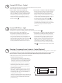
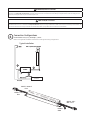
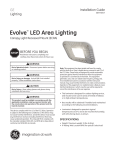
GE
Installation Guide
Lighting
IMMERSION
TM
LED Refrigerated Display Lighting
Vertical & Horizontal Cases
94625 100W LED Driver
GEPS6000NCCON-SY
BEFORE YOU BEGIN
Read these instructions completely and carefully.
FOR YOUR SAFETY
Read and observe all CAUTIONS and WARNINGS shown
throughout these instructions.
• Installation to be performed by factory trained service personnel only.
• For use inside a commercial refrigeration case with packaged foods only.
• Use this unit only in the manner intended by the manufacturer. If you have any questions, contact the manufacturer.
• Before installing, servicing or cleaning unit, switch power off at the service panel and follow appropriate lock out/tag out safety procedures
This device complies with part 15 of the FCC Rules. Operation is
subject to the following two conditions: (1) This device may not cause
harmful interference, and (2) this device must accept any interference
received, including interference that may cause undesired operation.
This Class [A] RFLD complies with the Canadian standard ICES-003.
Ce DEFR de la classe [A] est conforme à la NMB-003 du Canada.
NOTE:
This equipment has been tested and found to comply with the
limits for a Class A digital device, pursuant to part 15 of the FCC Rules.
These limits are designed to provide reasonable protection against
harmful interference when the equipment is operated in a commercial
environment. This equipment generates, uses, and can radiate radio
frequency energy and, if not installed and used in accordance with
the instruction manual, may cause harmful interference to radio
communications. Operation of this equipment in a residential area
is likely to cause harmful interference in which case the user will be
required to correct the interference at his own expense.
imagination at work
PREPARE ELECTRICAL WIRING
Electrical Requirements
• The power supply must be supplied with 100-240 VAC, 50/60 Hz, and connected to an individual properly grounded branch circuit, protected by a 15 or 20 ampere circuit breaker or time delay fuse.
• Wiring must be 2 wire with ground and rated for 75°C (167°F).
All wiring must be done to NEC or local electrical codes.
Grounding Instructions–Cable Direct
• This lighting system must be connected to a grounded metal, permanent wiring system, or an equipment grounding conductor must be run with the circuit conductors and be connected to the equipment grounding terminal.
CAUTION/ATTENTION
Risk of injury. While performing installations described, gloves, safety
glasses or goggles should be worn. / Risque de blessure. Lors de l’exécution
des installations décrites, des gants, des lunettes de sécurité ou des lunettes
de protection doivent être portées.
WARNING/AVERTISSMENT
Risk of electrical shock. Disconnect power before servicing or installing product.
LED Retrofit Kit Installation requires knowledge of luminaires electrical systems.
If not qualified, do not attempt installation. Contact a qualified electrician. Install
this kit only in the luminaires that have the construction features and dimensions
shown in the photographs and/or drawings. / Risque de choc électrique. Couper
le courant avant de réparer ou installer le produit. LED Retrofit Kit d’installation
nécessite la connaissance des systèmes luminaires électriques. Si vous n’êtes
pas qualifié, ne tentez pas l’installation. Contactez un électricien qualifié. Installez
ce kit seulement dans les luminaires qui ont les caractéristiques de construction
et les dimensions figurant sur les photographies et / ou des dessins.
1
Connect LED Driver - Output
• For retrofit, place LED driver in the location where the ballast was formerly located.
• Make output (DC) connections as noted below:
OPTION 1 (OEM) – USING 2-WAY CONNECTOR
Connect the LED Driver output leads to the LED
Light leads using the appropriate mating connector
(Tyco p/n 794896-1). Terminals installed should be
crimped using approved tooling and process per
Molex specifications. Ensure that the connector
cavities are correctly populated per the wire colors
shown on page 3. A
OPTION 2 (OEM) – USING TWIST-ON WIRE CONNECTORS
Remove the 2-way connector from the LED Driver
by cutting the wires near the connector and strip
the output leads. Using the appropriate wiring
diagram on page 3, connect the LED Driver output
leads to the LED Light leads using wire connectors
or other connection method approved for low
temperature usage and stranded cable. A
For non-dimming applications, cap the unused
wires with 5/32” (4mm) twist on wire connectors.
For Retrofit: Bundle and safely secure any unused
wires by way of approved wire ties and wire
connectors.
Connect LED Driver - Input
• Make input (AC) connections using one of the two options below:
• The LED Driver is required to be reliably bonded to the protective ground conductor. B
OPTION 1 (OEM) - USING 2-WAY CONNECTOR
Ground driver to metal portion of the door frame.
Connect the original Line and neutral wires (or
Line 1 and Line 2 wires for 240 nominal VAC) to the
2-way connector for the LED Driver input wires
using the appropriate mating connector (JST p/n C
VLR-02V). Ensure that the connector cavities are
correctly populated per the wire colors on page 3.
3
OPTION 2 (OEM) – USING TWIST-ON WIRE CONNECTOR
Ground driver to metal portion of the door frame.
Remove the 2-way connector from the LED Driver
by cutting the wires near the connector and strip
the input wires. Using the appropriate wiring
diagram on page 3, connect the original Line and
neutral wires (or Line 1 and Line 2 wires for 240
nominal VAC) to the LED Driver leads using twist
lock wire connectors or other connection method
approved for low temperature usage and stranded
cable. C
Dimming /Occupancy Sensor Contacts – Output (Optional)
• To enable dimming operation and/or occupancy sensors you must connect leads from occupancy sensor or control system (normally open contact) to the purple and gray leads of the power supply and adjust dimming switch as shown below.
Note: connection of occupancy sensor to the dimming leads will reduce light output to 20% normal output.
• Make output (contact closure) connections as noted below:
Connection of Dimming Control:
Connect the LED Driver dimming output leads to
the occupancy sensor or control system using wire
connectors or other connection method approved
for low temperature usage and stranded cable.
• The GEPS6000NCCON-SY LED Driver is capable of
step dimming from 100% power to 20% power
when used with a normally open contact closure
occupancy sensor system.
• When using the GEPS6000NCCON-SY for dimming applications, the dimming switch setting must be
switched to the left to enable the dimming feature.
The following is the only recommended usage of
occupancy sensors with the Immersion LED lighting system. Other methods, such
as using occupancy sensors to switch the LED driver
on and off is not recommended and will void the
product warranty.
DIMMING
SWITCH
2
Dimming
Dimming Enabled (20%)
Dimming Disabled (default)
DIMMING SWITCH
WARNING/AVERTISSMENT
Risk of electrical shock. Ensure that all connection points are sealed for damp location using the appropriate method per the NEC or local
electrical code. Risque de choc électrique. S’assurer que les points de raccordements sont scellés pour emplacement humide en employant une
méthode permise par le NEC ou par le code électrique local.
CAUTION/ATTENTION
Risk of injury. Do not overload LED Driver, 100-watts maximum per driver. Do not exceed the LED light bar loading limits specified on the light bar
installation instructions for a 100W driver. Risque de blessure. Ne pas surcharger l’alimentation à DEL. Maximum de 100 watts par alimentation. Ne
pas excéder les limites de charge maximale des alimentations telles que spécifiées dans les instructions d’installation.
4
Connection Configurations
For information on A, B, C, D, see Steps 1, 2, and 3.
Refer to LED Light Bar installation instructions for LED light bar wiring configurations.
Typical Installation
LED LIGHT LOAD
TERMINAL BLOCK
(AC SOURCE)
WHITE - Neutral
Pin 2
BLACK - Line
Pin 1
BLACK - Pin 1
RED - Pin 2
PURPLE
GRAY
This product is intended to be used as a lamp control gear that is installed after the mains control switch.
GE Lighting Solutions • 1-888-MY-GE-LED (1-888-69-43-533) • www.gelighting.com
GE Lighting Solutions, LLC is a subsidiary of the General Electric Company. Immersion is a trademark of GE Lighting. The GE brand and logo are trademarks of the General Electric Company.
Information provided is subject to change without notice. All values are design or typical values when measured under laboratory conditions.
GE2024-3246
© 2014 GE 94625 081414