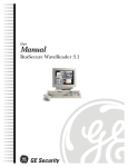
1
BusSecure Mobile Digital Video Recorder © 2003 Kalatel, a GE Interlogix company All Rights Reserved. Any GE Interlogix, Kalatel division, software supplied with GE Interlogix, Kalatel division, products is proprietary and furnished under license and can be used or copied only in accordance with the terms of such license. This document contains proprietary information that is protected by copyright. No part of this document may be reproduced or transmitted in any form or by any means without the prior written permission of GE Interlogix, Kalatel division. The information contained in this document is subject to change without notice. GE Interlogix, Kalatel division, in keeping pace with technological advances, is a company of product innovation. Therefore, it is difficult to ensure that all information provided is entirely accurate and up-to-date. GE Interlogix, Kalatel division, accepts no responsibility for inaccuracies or omissions and specifically disclaims any liabilities, losses, or risks, personal or otherwise, incurred as a consequence, directly or indirectly, of the use or application of any of the contents of this document. For the latest product specifications, visit GE Interlogix, Kalatel division, online at www.kalatel.com or contact your GE Interlogix, Kalatel division, sales representative. For technical support before and after installation, call 800469-1676. Technical support is available 24 hours a day, 7 days a week. Call: Tech Support Monday through Friday) Tech Support Main Fax: Tech Support Main Web: www.kalatel.com 0150-0263A / May 2003 800-469-1676 (6 A.M. – 5 P.M. PST 541-740-3589 (all other times) 800-343-3358 or 541-754-9133 541-752-9096 (available 24 hours a day) 541-754-7162 This equipment has been tested and found to comply with the limits for a Class A digital device, pursuant to part 15 of the FCC Rules. These limits are designed to provide reasonable protection against harmful interference when the equipment is operated in a commercial environment. This equipment generates, uses, and can radiate radio frequency energy and, if not installed and used in accordance with the instruction manual, may cause harmful interference to radio communications. You are cautioned that any changes or modifications not expressly approved by the party responsible for compliance could void the user's authority to operate the equipment. BusSecure User Manual Table of Contents TABLE OF CONTENTS BEFORE YOU BEGIN ..........................................................................................................4 1 THEORY OF OPERATIONS .............................................................................................5 1.1 DIGITAL VIDEO RECORDING ..........................................................................................................5 1.2 VIEWING AND RETRIEVING IMAGES ................................................................................................5 1.3 FEATURES OF A BUSSECURE SYSTEM ...........................................................................................6 2 HARDWARE INSTALLATION ...........................................................................................7 2.1 TOOLS NECESSARY FOR INSTALLATION ..........................................................................................7 2.2 DETERMINING A SYSTEM LAYOUT ..................................................................................................8 2.3 RUNNING CAMERA CABLES ..........................................................................................................9 2.4 INSTALLING CAMERA ASSEMBLIES ...............................................................................................10 2.4.1 Installing Surface-Mount Camera Assemblies ...............................................................10 2.4.2 Installing Flush-Mount Camera Assemblies...................................................................11 2.4.3 Adjusting Cameras for Functional Field of View.............................................................12 2.5 INSTALLING THE IMPACT SENSOR (OPTIONAL) ...............................................................................14 2.6 INSTALLING THE PANIC BUTTON (OPTIONAL) .................................................................................15 2.7 INSTALLING THE MICROPHONE (OPTIONAL) ...................................................................................15 3 DVR INSTALLATION AND WIRING ................................................................................16 3.1 MOUNTING THE DVR .................................................................................................................16 3.2 W IRING THE DVR......................................................................................................................17 3.2.2 Alarm and Trigger Inputs...............................................................................................19 3.2.3 Status Output Connections ...........................................................................................20 3.2.4 Audio Connections........................................................................................................21 3.2.5 Input Power Connections ..............................................................................................21 4 BUSSECURE CONFIGURATION ....................................................................................22 4.1 CONFIGURATION .......................................................................................................................23 4.1.1 Configure Network ........................................................................................................24 4.1.2 Configure Cameras.......................................................................................................25 4.1.3 Configure Inputs ...........................................................................................................26 4.1.4 Configure System .........................................................................................................27 4.2 SOFTWARE UPGRADE ................................................................................................................28 5 TROUBLESHOOTING ...................................................................................................29 APPENDIX A. CAMERA MOUNTING PLATE TEMPLATE ........................................................32 APPENDIX B. INSTALLATION CHECK SHEET .......................................................................33 APPENDIX C. DVR CONFIGURATION WORKSHEET .............................................................34 W ARRANTY AND RETURN INFORMATION ..............................................................................................36 0150-0263A / May 2003 3 Before You Begin BusSecure User Manual BEFORE YOU BEGIN Read these instructions before installing or operating this product. Note: This installation should be made by a qualified service person and should conform to local codes. This manual provides installation and operation information. To use this document, you must have the following minimum qualifications: Ÿ A basic knowledge of CCTV systems and components Ÿ A basic knowledge of electrical wiring and low-voltage electrical hookups Intended use Use this product only for the purpose for which it was designed; refer to the product specification and user documentation. Customer Support For assistance in installing, operating, maintaining, and troubleshooting this product, refer to this document and any other documentation provided. If you still have questions, please contact GE Interlogix, Kalatel division Technical Support and Sales: Kalatel, a division of GE Interlogix, Inc. Call: 800-469-1676 Fax: 541-752-9096 Note: you should be at the equipment and ready with details before calling Technical Support. Conventions Used in this Manual Boldface or button icons highlight command entries. The following WARNING, CAUTION, and Note statements identify potential hazards that can occur if the equipment is handled improperly: * WARNING: Improper use of this equipment can cause severe bodily injury or equipment damage. ** CAUTION: Improper use of this equipment can cause equipment damage. Note: Notes contain important information about a product or procedure. * This symbol indicates electrical warnings and cautions. ** This symbol indicates general warnings and cautions. 4 0150-0263A / May 2003 BusSecure User Manual 1 Theory of Operations THEORY OF OPERATIONS BusSecure is an industry-specific security camera system developed to help solve problems experienced by fleet operators. It is a digital video recording system that can support up to four cameras in a mobile environment and store captured images in a vehicle-mounted digital video recorder (DVR). Images can then be viewed and examined later. 1.1 DIGITAL VIDEO RECORDING The central component of the BusSecure system is a high-quality DVR, which records images from up to four cameras (monochrome or color, NTSC or PAL) with single-channel audio and information such as the time, date, and vehicle number. Image storage capacity can be adjusted by recording speed, selected resolution, and drive size. The DVR begins capturing images as soon as the vehicle’s engine is started and continues to record as long as the vehicle is running. When the available storage capacity is full, the DVR will automatically purge the oldest image data to make room for new image data. Tagged images (images recorded because of alarm activation) can be protected from being overwritten for a user-designated period of time (the default setting is 30 days) or can be protected from being over written at all. 1.2 VIEWING AND RETRIEVING IMAGES The captured digital images are stored as monochrome or color files, and are taken from the DVR and TM downloaded to a computer with the BusSecure WaveReader software. The DVR connects through an Ethernet connection to a standard desktop PC or Laptop installed with a Windows 98/2000/NT/XP operating system. When the DVR is connected to a PC or Laptop with the WaveReader software, images can be viewed and transferred to long-term storage media such as DAT tapes, floppy disks, or recordable CDs. 0150-0263A / May 2003 5 Theory of Operations 1.3 BusSecure User Manual FEATURES OF A BUSSECURE SYSTEM A BusSecure system consists of the required equipment and the accessories shown in Figure 1. Aluminum housing Microphone Camera Panic Button Up to four cameras per system Impact Sensor RG179 Siamese coaxial cable DVR assembly Figure 1. 6 Required and optional features of a BusSecure system 0150-0263A / May 2003 BusSecure User Manual Hardware Installation HARDWARE INSTALLATION 2 The BusSecure/DVR digital video recording system supports up to four cameras, and an optional impact sensor, panic button, and microphone. Note: Most BusSecure products are not supplied with mounting hardware. Exceptions are noted in the appropriate sections of the manual. 2.1 TOOLS NECESSARY FOR INSTALLATION Ÿ Laptop / viewing station Ÿ Electrical volt meter Ÿ BNC crimper Ÿ Molex pin crimper Ÿ Riv-nut gun Ÿ Socket set up to 5/8 in. Ÿ Wrenches up to 5/8 in. Ÿ Phillips and flathead screwdrivers Ÿ Solder gun with solder Ÿ Wire strippers Ÿ Drill Ÿ Drill bits up to 5/8 in. Ÿ Locktite (blue) Ÿ Torx bit secured #10 Ÿ Wire snake Ÿ Extension cords Ÿ 8-in. tie wraps Ÿ Electrical tape Ÿ Heat shrink Ÿ Spare BNCs Ÿ Molex pins and 4-pin housing Ÿ Electrical connections (ends, lugs, etc.) Ÿ P1, and P2 terminal blocks Ÿ General tools Ÿ Hole saws up to 1 1/8 in. 0150-0263A / May 2003 7 Hardware Installation 2.2 BusSecure User Manual DETERMINING A SYSTEM LAYOUT Figure 2 is an example camera layout for a bus application. Note: For installation of these cameras, see their respective manuals. Note: Camera layout and fields of view will vary from vehicle to vehicle, and each customer will determine camera names or descriptions. Camera types, fields of view, and cable lengths will be determined by the customer-specific system layout. The Front Door camera is located at the front of the bus over the driver’s head, looking at the front passenger entry. The Forward Facing camera is located in the front of the bus, looking in front of the bus. The Front to Rear camera is located in the front of the bus, looking down the center aisle to the rear of the bus. The Rear Facing camera is located at the back of the bus, looking behind the bus. Figure 2. 8 Typical camera placement and fields of view 0150-0263A / May 2003 BusSecure User Manual 2.3 Hardware Installation RUNNING CAMERA CABLES CAUTION When installing cables, follow these guidelines: Avoid excessive lengths of cable at the control and device end. Excess cable should be pulled back to a duct area where it can be folded and secured. Leave a service loop as directed for specific devices. Cables should not come into contact with bare metal edges, light ballasts, or magnetic speaker coils. If ballasts and speaker coils cannot be avoided, cross them perpendicularly. Cables that are secured with cable-ties should not be tightened to the extent that the cable is compressed or damaged. The cables should not be crimped, crushed, or severely bent. When passing cables through tapping plates or metal side walls of the vehicle, insert grommets in the holes to protect the cable, if possible This may not be feasible in a retrofit situation. If it is not feasible, make sure that the protective outer CL2 jacket is maintained when passing cable through hole. When pulling cable through the conduit, do not jerk or over-pull the cables. These actions will stretch and damage the cable. Attach a pull-line to the cable jacket, not to the connectors. 1) Route cables from each camera location to the DVR location as determined by your customerspecific system layout. Figure 3 shows an example system layout. 2) If cables must be pulled through vehicle walls with limited access or conduit, attach pull lines to the cables jackets, and gently pull cables through the appropriate routing paths. 3) After reaching camera locations, leave enough cable for a 6-inch service loop at each location. 4) Pull any excess cable back into the duct area where it can be folded and secured. 4 DVR Location Figure 3. Typical camera cabling layout 0150-0263A / May 2003 9 Hardware Installation 2.4 BusSecure User Manual INSTALLING CAMERA ASSEMBLIES The BusSecure system will support up to four cameras (color and/or monochrome). Cameras supported by the BusSecure system can provide a 1.0 V pk-pk composite analog video signal, either NTSC or PAL, at 75 ohm (CCTV standard). 2.4.1 INSTALLING SURFACE-MOUNT CAMERA ASSEMBLIES Surface-mount camera housings are typically mounted to the ceiling, but can be mounted to any flat vehicle surface. Note: In some installations, it is necessary to use a metal tapping plate behind the mounting surface. If a tapping plate is used, prepare it in the same way as the mounting surface (i.e., drill a cable entry hole and mounting holes in the appropriate locations). 1) Use the template in Appendix A to mark the location of the cable-entry hole and two mounting holes. See Figure 4. 2) Using a 3/16-inch (5 mm) (drill bit, drill the two mounting holes. 3) Using a 1-inch (25.4 mm) drill bit, drill the cable entry hole. 4) Install a 3/4-inch (20 mm) (interior diameter) grommet on the cable entry hole, or where feasible. 5) Connect the video and power cables to the camera, and feed the excess cable into the vehicle’s duct area. 6) Mount the camera and mounting plate to the vehicle surface (and tapping plate, if used). See Figure 5. 7) Refer to section 2.4.3 to align the camera’s field of view to the appropriate angle. 8) Secure the surface-mount housing to the mounting plate with the four 3/8-inch tamper-resistant tamper-torque machine screws provided, using a bit of blue locktite. See Figure 6. Figure 5. Mounting plate installation 10 Cable entry hole Mounting holes Figure 4. Mounting hole locations Figure 6. Surface-mount housing installation 0150-0263A / May 2003 BusSecure User Manual Hardware Installation 2.4.2 INSTALLING FLUSH-MOUNT CAMERA ASSEMBLIES There are two types of flush-mount cameras—square and angled. Flush-mount camera assemblies are mounted flush with the side panels of the vehicle. Note: The square bezel that holds the glass camera cover has countersunk holes in the back side that cover the two housing screws. The housing and bezel screws are separate to allow access to the camera for focusing and adjusting while the housing is held firmly in place. 1) Verify that there is at least 6 inches (153 mm) of clearance behind the mounting location. 2) Cut a 3.4- by 3.4-inch (81 mm) hole in the appropriate location on the mounting surface. 3) Using the housing as a template, mark the location of the mounting holes. 4) Using a 3/16-inch (5 mm) drill bit, drill the mounting holes. 5) Connect the video and power cables to the camera assembly. 6) Mount the camera assembly to the vehicle surface using two fasteners screwed into panel nuts. See Figure 7 or 8 (depending on the type of camera assembly being installed). Figure 7. Angled flush-mount housing installation Figure 8. Square flush-mount housing installation 7) Refer to section 2.4.3 Adjusting Cameras for Functional Field of View to align the camera’s field of view according to the appropriate angle. 8) Attach the cover plate to the housing. If you are installing a square housing, you must drill two additional mounting holes for the cover plate. See Figure 9 or 10. 0150-0263A / May 2003 11 Hardware Installation Figure 9. Angled flush-mount housing cover BusSecure User Manual Figure 10. Square flush-mount housing cover 2.4.3 ADJUSTING CAMERAS FOR FUNCTIONAL FIELD OF VIEW Depending on location, the camera’s position might have to be adjusted to provide the best field of view. Adjusting the camera positioning might include altering the position of the camera and, for surface-mount cameras, using a spacer. To adjust the angle of the camera, see Figure 11 and perform the following: 1) Loosen the camera’s pivot screws. 2) Rotate the camera to the correct angle. 3) Retighten the pivot screws. Surface-mount cameras are configured at the factory to be installed onto the ceiling of the vehicle. If you are installing a surface-mount camera on the side of the vehicle, see Figure 12 and perform the following to rotate the camera lens: Figure 11. Adjusting the camera angle CAUTION Over-tightening the set and pivot screws can damage the camera’s lens. 1) Loosen the setscrew on the top of the camera assembly. 2) Rotate the camera assembly 90°. 3) Retighten the setscrew. Figure 12. Rotating the camera 12 0150-0263A / May 2003 BusSecure User Manual Hardware Installation To adjust the camera according to where it will be mounted on the vehicle, perform the following: 1) Figure 13 shows orientation of a camera for mounting on the curbside of the bus, the backside of the bus, or in a forward-facing position on the dashboard. Note that the lens set screw ( ) and the wiring harness ( ) are positioned at the top of the camera. 2) For cameras mounted on the streetside of the bus or surface-mounted facing backward, remove the two side-set screws, as shown in Figure 14, and lift the camera out of its bracket. 3) Rotate the entire camera assembly 180º. See Figure 14. 4) Insert the camera into the bracket, and replace set screws. The lens set screw and the wiring harness should now be positioned at the bottom of the camera. See Figure 15. Figure 13. Camera orientation for curbside mounting. Figure 14. Rotating the camera for street-side orientation Figure 15. Camera orientation for street-side mounting 0150-0263A / May 2003 13 Hardware Installation 2.5 BusSecure User Manual INSTALLING THE IMPACT SENSOR (OPTIONAL) The Impact Sensor is typically mounted near the DVR and comes with a 7-foot cable that terminates in the DVR. CAUTION Do not install the Impact Sensor until you have tested its functionality on each vehicle. The Impact Sensor should be mounted on a flat, stable surface and secured to the frame of the vehicle. The mounting surface must not be subject to vibrations. 1) Using the Impact Sensor as a template, mark the location of the two mounting holes. The Impact Sensor should be aligned so that it is square with the front and rear of the vehicle. See Figure 16. 2) Drill the mounting holes with an appropriate size drill bit. 3) Mount the Impact Sensor. 4) Route the provided cable to the DVR. Connections to the P1 terminal block on the DVR Rear Panel Assembly are as follows: N/C wire (green or white) to terminal 1, common wire (black) to terminal 2, positive wire (red) to terminal 18. Align square with the front and rear of the vehicle Align square with the sides of the vehicle Cable to DVR Rear Panel Assembly Figure 16. Aligning the Impact Sensor 14 0150-0263A / May 2003 BusSecure User Manual 2.6 Hardware Installation INSTALLING THE PANIC BUTTON (OPTIONAL) The Panic Button is typically installed within reach of the driver. Note: There are two versions of the panic button: one with a key reset and one without. See Figures 17 and 18. Figure 17. Panic button without key reset Figure 18. Panic button with key reset 1) Using the panic button as a template, mark the location of the two mounting holes. 2) Using a 6/32-inch drill bit, drill the mounting holes. 3) Using a 3/4-inch drill bit, drill a hole for the panic button’s wiring. 4) Splice a six-conductor 18 AWG cable to the panic button’s wiring. Note: The panic button with key reset (Figure 18) has six wires, and the panic button without key reset (Figure 17) has only five. The N/C and common wires are both yellow and are interchangeable. 5) Route the cable to the DVR. Connections to the P1 terminal of the DVR Rear Panel Assembly are as follows: N/C and common (2 wires, both yellow) to terminals 3 and 4, normal wire (green) to terminal 13, check wire (red) to terminal 15, positive wire (gray) to terminal 18, negative wire (white, present only on the panic button with key reset) to terminal 17. 6) Mount the panic button. 2.7 INSTALLING THE MICROPHONE (OPTIONAL) The BusSecure microphone (Figure 19) is typically mounted in the head sign area near the driver. Refer to the instructions provided with the microphone for installation procedures. A two-conductor shielded microphone cable and a twisted pair power cable (18 AWG wire is recommended) must be routed from the microphone to the DVR location. The shielded wire is attached at the microphone end only. A service loop should be left at the microphone end. See Figure 29. Figure 19. BusSecure microphone 0150-0263A / May 2003 15 DVR Installation and Wiring 3 BusSecure User Manual DVR INSTALLATION AND WIRING A removable hard disk drive (HDD) is housed within the DVR that is mounted to the vehicle. All connections are made through the terminals at the back of the unit. See Figure 22. Removable HDD DVR Figure 20. DVR assembly 3.1 MOUNTING THE DVR Note: The DVR can be mounted in various orientations (except upside down), but you must leave enough space to pull the latch and remove the HDD. See Figure 21 and perform the following: 1) Mount the mounting plate ( ) to the vehicle using four nuts and bolts (not provided) (1/4-20-inch bolts ( ) are recommended). 2) Remove the four acorn nuts ( ) and locking washers ( ) from the top of the vibration isolators ( ) (Do not remove the vibration isolators ( ) or the bolts and nuts holding them in place.) 3) Place the DVR outer housing ( ) back onto the mounting plate by lining up the holes in the mounting brackets ( ) with the bolts in the vibration isolators. 4) Reattach the four acorn nuts and locking washers. 16 Figure 21. Mounting the DVR 0150-0263A / May 2003 BusSecure User Manual 3.2 DVR Installation and Wiring WIRING THE DVR All wire connections between the DVR and auxiliary devices are made through the DVR’s Rear Panel Assembly (see Figure 22). ETHERNET 10/100 POWER CAM1 CAM2 FUSE CAM3 CAM4 GND P2 P1 1 2 3 4 5 6 7 8 9 10 11 12 13 14 15 16 17 18 19 20 Ethernet connector (Use of this connector is optional) Four-pin Molex (power management board) BNC connectors (Video inputs Cam 1 – Cam 4) P2 Terminal Block (Alarm inputs/outputs, status indication, and impact sensor) (Upper Connector) P1 Terminal Block (Camera connections) (Lower Connector) Figure 22. DVR Rear Panel Assembly connections CAUTION: Be very careful that you do not confuse the P1 terminal block with the P2 terminal block. The P2 terminal block is positioned above the P1 terminal block. The P1 terminal block is used strictly for camera connections; the P2 terminal block is used strictly for input/output wiring. 3.2.1.1 P1 T ERMINAL BLOCK CONNECTIONS (LOWER CONNECTOR ) The P1 terminal block provides power to the vehicle’s cameras. 1) Remove the P1 terminal block ( in Figure 22) from the rear panel assembly by loosening its mounting screws and pulling it out of its socket. 2) Make connections as shown in Figure 23. To make connections, strip each wire 3/8 of an inch, insert it into the appropriate slot, and tighten the terminal screw. 3) Reinstall the P1 terminal block. 0150-0263A / May 2003 17 Ground +12VDC 5 6 7 8 9 RS485B +12VDC 4 +5VDC Ground 3 RS485A +12VDC 2 Ground Ground 1 BusSecure User Manual +12VDC Ground DVR Installation and Wiring 10 11 12 13 14 15 16 17 18 19 20 Power 1 5V power (for future use) Power 2 RS485 communication (for future use) Power 3 Power 4 Figure 23. P1 terminal block connections (Lower Connector) 3.2.1.2 BNC CONNECTIONS Connect each camera’s video output cable to its corresponding BNC connector on the rear panel assembly (see Figure 24). CAM1 CAM2 CAM3 CAM4 Figure 24. BNC connectors 18 0150-0263A / May 2003 BusSecure User Manual DVR Installation and Wiring 3.2.2 ALARM AND TRIGGER INPUTS The BusSecure system allows for four inputs, which can be defined as either triggers or alarms. The Impact Sensor and Panic Button are both examples of alarm inputs. When the trigger is activated, it will open the normally closed connection, activating the alarm. Refer to the system specific layout for the location and types of inputs used in your installation. 1) Remove the P2 terminal block ( in Figure 22) from the rear panel assembly by loosening its mounting screws and pulling it out of its socket. 2) Each trigger device must have a normally closed connection with the DVR and be connected as shown in Figure 25. All wires should be stripped 3/8 of an inch. 1 2 3 6 7 8 Input 1 Input 4 Input 2 Ground Input 3 12 VDC AUDIO - AUDIO + GND 9 12 VDC GND GND 5 Normally Closed GND 4 Normally Closed Normally Closed GND Normally Closed Note: Terminal 18 also may be used for a panic button or impact sensor (up to three wires can go into terminal 18). 10 11 12 13 14 15 16 17 18 19 20 Audio Connections Figure 25. Alarm/trigger connections to P2 terminal board (Upper Connector) 3.2.2.1 IMPACT SENSOR CONNECTIONS The Impact Sensor’s N/C wire (green or white) and common wire (black) connect to one of the pairs of input terminals shown in Figure 26. Its +12-VDC wire (red) connects to terminal 18. See Figure 26. Figure 26. Impact Sensor input connections 0150-0263A / May 2003 19 DVR Installation and Wiring BusSecure User Manual 3.2.2.2 PANIC BUTTON CONNECTIONS The Panic Button’s N/C wire and common wire connect to one of the pairs of input terminals as shown in Figure 27. Note: The Panic Button also has wires that are used for status outputs. See section 3.2.4. Figure 27. Panic Button input connections 3.2.3 STATUS OUTPUT CONNECTIONS The BusSecure system provides two status outputs on the P2 terminal block for optional use. The most common uses for these outputs are as interfaces to a vehicle relay system or lights. To interface with a vehicle relay system, contact the vehicle manufacturer. To connect the status lights on the Panic Button to the status outputs, see Figure 28 and perform the following: 3) Connect the positive wire (gray) to terminal 18. 4) If you are installing a Panic Button with a key reset, connect the negative wire (white) to terminal 17. 1 2 3 4 5 6 7 8 9 Positive Connect the check wire (red) to terminal 15. GND 2) Check Connect the normal wire (green) to terminal 13. Normal 1) 10 11 12 13 14 15 16 17 18 19 20 Figure 28. Panic Button output connections 20 0150-0263A / May 2003 BusSecure User Manual DVR Installation and Wiring 3.2.4 AUDIO CONNECTIONS in Figure 22) Note: For instructions on making wiring connections at the microphone end, refer to the instructions provided by the manufacturer. AUDIO - B AUDIO + Connect the audio and power cables from the microphone as shown in Figure 29. A GND 2) Remove the P2 terminal block ( from the DVR back assembly. 12 VDC 1) 17 18 19 20 Twisted-pair power cable Audio cable (shielded) Figure 29. Audio connections 3.2.5 INPUT POWER CONNECTIONS Power is supplied through the DVR’s four-pin Molex connector, located on the DVR Rear Panel Assembly ( in Figure 22). The following connections from the vehicle junction box must be made to the DVR: +12-VDC continuous with 6-amp circuit breaker source, circuit battery ground, chassis ground, and +12-VDC ignition/engine running with source fused not greater than 1 amp. See Figure 30. 1) Run a four-conductor 18-AWG wire from the vehicle power source to the DVR location. 2) Make connections to the vehicle source (contact the vehicle manufacturer for information on connecting to the vehicle power source). 3) Crimp the wire pins using a Molex crimper, and make connections to the DVR’s four-pin Molex according to Figure 30. 4) Test the four-pin Molex wire-harness for power (both continuous 12 VDC and engine running/ignition). Note: For a working definition of engine running/ignition, contact the vehicle manufacturer. 12 VDC continuous battery: 12 VDC: 10 - 15-amp circuit breaker Circuit battery ground Chassis ground 5) Plug the Molex connector into the power connection on the DVR Rear Panel Assembly ( in Figure 22). Check the power connections with a voltage meter to ensure correct polarity and connections. 0150-0263A / May 2003 12 VDC engine run/ignition: 12 VDC: minimum of 6amps, no greater than 12 amps Figure 30. Input power wiring to DVR 21 BusSecure Configuration 4 BusSecure User Manual BUSSECURE CONFIGURATION BusSecure configuration is achieved through a web based configuration utility. The BusSecure must be completely installed, powered up, and connected to a PC or Laptop through a network. To configure the BusSecure perform the following: 1) Launch a web browser on the PC. We recommend MicroSoft Internet Explorer version 5.0 and above. Enter the BusSecure’s default IP address of 3.18.173.0 in the browser’s address bar. 2) When successfully connected the Enter Network Password window will appear. Enter the default User Name and Password of admin. 3) Entering the correct username and password will cause the configuration utilities home page to display. Configuration and Upgrade operations can be initiated from this page. 22 0150-0263A / May 2003 BusSecure User Manual 4.1 BusSecure Configuration CONFIGURATION Click on Configure the unit to display the configuration page. The configuration options on this page include: • Configure Network • Configure Cameras • Configure Inputs • Configure System 0150-0263A / May 2003 23 BusSecure Configuration BusSecure User Manual 4.1.1 CONFIGURE NETWORK Click on the Configure Network option to display the following screen: The configuration options on this page include: • Network Parameters - The IP Address and Subnet Mask • User ID Settings – Username and Password A Reset Defaults button is also available. Click the Accept button to enter the changes or click the Reset button to undo any changes. Note: Once the Accept button is clicked, the buttons on the bottom of the screen change to a Save and Cancel button. Clicking on Save at this point will cause your changes to be written and the BusSecure to reboot. If you have more changes to make on the other configuration screens; first click Accept and then use the [Home][Configure][Upgrade] selections at the top of the page to navigate back to the Configuration pages. 24 0150-0263A / May 2003 BusSecure User Manual BusSecure Configuration 4.1.2 CONFIGURE CAMERAS Click on the Configure Camera option to display the following screen: The configuration options on this page include: • Name – User supplied camera name or designation. • Type – Camera type, Color or Monochrome. • Normal Record Rate* – Fast, Normal, or Slow. • Normal Quality – High, Medium, or Low. • Trigger Record Rate* – Fast, Normal, or Slow. • Trigger Quality – High, Medium or Low. • AGC Level – Automatic Gain Control (Positive numbers makes the images brighter, Negative numbers make the images darker, and 0 is the default value). Select from +5 to –5. A Reset Defaults button is also available. Click the Accept button to enter the changes or click the Reset button to undo any changes. *Note: The Normal and Trigger record rate programming feature of any camera in the system depends on the capture rate of the other cameras. Therefore, if you want camera 1 to capture images at a faster rate than other cameras in the system, you must set camera 1’s capture rate (Normal or Trigger) to fast and the other cameras capture rates to normal or slow. 0150-0263A / May 2003 25 BusSecure Configuration BusSecure User Manual Note: Once the Accept button is clicked, the buttons on the bottom of the screen change to a Save and Cancel button. Clicking on Save at this point will cause your changes to be written and the BusSecure to reboot. If you have more changes to make on the other configuration screens; first click Accept and then use the [Home][Configure][Upgrade] selections at the top of the page to navigate back to the Configuration pages. 4.1.3 CONFIGURE INPUTS Click on the Configure Inputs option to display the following screen: The configuration options on this page include: • Name – User supplied input name or designation. • Type – Input type, Alarm, Trigger or Not Used. • Pre Trigger Time – Various increments from 0 seconds to 10 minutes. • Post Trigger Time – Various increments from 0 seconds to 10 minutes. • Camera Group – Select from Cameras 1 through 4. A Reset Defaults button is also available. Click the Accept button to enter the changes or click the Reset button to undo any changes. Note: Once the Accept button is clicked, the buttons on the bottom of the screen change to a Save and Cancel button. Clicking on Save at this point will cause your changes to be written and the BusSecure to reboot. If you have more changes to make on the other configuration screens; first click Accept and then use the [Home][Configure][Upgrade] selections at the top of the page to navigate back to the Configuration pages. 26 0150-0263A / May 2003 BusSecure User Manual BusSecure Configuration 4.1.4 CONFIGURE SYSTEM Click on the Configure System option to display the following screen: The configuration options on this page include: • Vehicle ID – User supplied vehicle name or designation. • System Framerate – In Frames Per Second. • Minimum Surveillance Storage Time – In Days. • Minimum Alarm Storage Time – In Days. • Audio Level – Positive numbers increase the Audio level. • Audio Enabled – Checkmark to enable. • Auto Daylight Savings Time – Checkmark to enable. • Video Standard – Select from PAL or NTSC. A Reset Defaults button is also available. Click the Accept button to enter the changes or click the Reset button to undo any changes. Note: Once the Accept button is clicked, the buttons on the bottom of the screen change to a Save and Cancel button. Clicking on Save at this point will cause your changes to be written and the BusSecure to reboot. If you have more changes to make on the other configuration screens; first click Accept and then use the [Home][Configure][Upgrade] selections at the top of the page to navigate back to the Configuration pages. 0150-0263A / May 2003 27 BusSecure Configuration 4.2 BusSecure User Manual SOFTWARE UPGRADE Click on Upgrade the unit to display the configuration page. Click on the Browse button and navigate to the upgrade file. Click on the Send File button. The following screen will appear. Click the Confirm button to execute the upgrade process. Upon completion the BusSecure will reboot and the upgrade process will be complete. 28 0150-0263A / May 2003 BusSecure User Manual Troubleshooting TROUBLESHOOTING 5 FACTORY SETTINGS: To reset the factory settings, remove the cover panel and hold down the indicated button ( ) for 5 seconds. This action will restore the default IP address to 3.18.173.0. BusSecure Figure 31. Location of factory reset button OPTIONAL STATUS LIGHTS: The status lights will alert you to the status of the DVR. DVR status lights should not be confused with DVR LEDs. The LEDs are located on the front of the removable DVR unit. The term status lights is used to refer to any lights or LEDs connected to the two outputs from the DVR, such as the BusSecure Panic Button. Status lights can be mounted anywhere depending upon the installation and are optional devices. Note: Some properties customize the DVR status outputs and use another device (such as an IO or PLC) to control the lights. Output 1 corresponds to Check System and Output 2 corresponds to Normal. Output 2: the DVR is running and capturing images. Output 1 and 2: the DVR is running and capturing images with an exception (e.g., loss of signal from a camera). Check the Recorder Log of the DVR to investigate further. Output 1: the DVR has encountered an error and is not capturing images. No lights: the DVR is not running. POSSIBLE CAUSES FOR A “CHECK SYSTEM ” STATUS LIGHT ON (in conjunction with a normal status light if installed): • Camera failure • Camera enabled but not installed • Event data deleted before the configured minimum time has passed • Surveillance data deleted before the configured minimum time has passed 0150-0263A / May 2003 29 TroubleShooting BusSecure User Manual REMOVABLE DVR: LEDS FROM LEFT TO RIGHT : Processor is writing to the hard drive (flashing green). : 12-V power supply present (solid green). Figure 32. Front Panel LEDs BUSSECURE UNIT DOES NOT START UP WITH VEHICLE IGNITION To test input voltage: remove the 4-pin Molex connector from the connection box of the DVR. Verify that when the ignition is off, the only voltage present is 12 VDC continuous (pin #1). Verify that when the engine is started, there is 12 VDC continuous (pin 1) and 12 VDC vehicle running voltages are present (pin 4). The DVR will not start without both power sources. Visually verify that the pins of the 4-pin Molex connector are properly crimped and inserted in the connector. BUSSECURE UNIT STARTS UP BUT DOES NOT APPEAR TO BE CAPTURING IMAGES LED LIGHTS AND ON THE FRONT OF THE DVR ARE NOT ALTERNATELY FLASHING 1) The DVR will not capture images if the key lock of the unit is open or unlocked. Close and lock the door, then turn off the vehicle. After the vehicle has shut down, restart the engine. 2) Shortly after the DVR restarts, image capture can be verified by the green status light (or combination of green and red status lights). BUSSECURE OPERATING NORMALLY BUT STATUS LIGHTS ARE NOT ILLUMINATING All status lights will be turned off after the DVR has shutdown completely. The status lights are supplied with 12 VDC continuous power from the vehicle. Verity that continuous voltage is present at the status light. The ground for the status lights is supplied by the DVR connection box. To check the ground output with a voltage meter, perform the following: 1) Place the positive meter probe onto an unused 12 VDC DVR output on the P1 or P2 terminal block (see Figure 21). 2) Place the negative meter probe into terminal 13 of the P2 terminal block. 30 0150-0263A / May 2003 BusSecure User Manual 3) Troubleshooting Terminal 13 of the P2 terminal block is the normal operation output. Voltage should be observable on the meter when the BusSecure is recording normally. Note: Voltage may vary from +5 VDC to +12 VDC, depending on the type of status indicator installed. 4) If voltage is not present, remove any wires that are connected to terminal 13 and repeat steps 1 through 4. 5) Repeat steps 1 through 5 for terminal 15 of the P2 terminal block. On terminal 15, voltage will only be present under a fault condition and at startup. 6) If the vehicle power and the DVR’s output of ground are both present at the light, but the light is not illuminating, it may be necessary to troubleshoot the vehicle wiring or replace the status light. LOSS OF VIDEO (IN CAPTURED IMAGES) CHECK FOR VIDEO AT THE BUSSECURE CONNECTION BOX AND THE CAMERA 1) If there is no video displayed, verify on the two-pin Molex camera power connector that 12 VDC is present. 2) Verify that the power connection on the camera is intact. 3) Verify that the power connection on the P1 terminal strip is correct. 4) Check the integrity of the coaxial cable and the BNC connectors. 5) Ensure that the BNC connectors at the DVR and camera have not been damaged or pulled apart. CHECK THE INTEGRITY OF THE COAXIAL CABLE 1) Disconnect the coaxial cable from the camera and DVR connection box. 2) Meter the coaxial cable by placing a jumper from the center conductor (video) of the BNC to the outer part of the BNC (ground). 3) Use a meter on the other end of the coaxial cable to check for resistance by placing one probe on the center conductor and the other probe on the outer part of the BNC. 4) Remove the jumper and meter one end of the disconnected coaxial cable. There should be no resistance. 0150-0263A / May 2003 31 Appendix A BusSecure User Manual APPENDIX A. CAMERA MOUNTING PLATE TEMPLATE (All measurements shown in inches) 32 0150-0263A / May 2003 BusSecure User Manual Appendix B APPENDIX B. INSTALLATION CHECK SHEET Vehicle ID DVR Serial Number IP Address Technician Item 12 VDC continuous power–fuse or circuit breaker Battery ground Chassis ground 12 VDC bus running–fuse or breaker SAS N/C input Impact Sensor input Normal status negative output Check status negative output Camera cables 1 – 4 Camera cable BNCs 1 – 4 Camera 1 field of view Camera 2 field of view Camera 3 field of view Camera 4 field of view System enclosure secure Camera cables Camera cable BNCs Date: 0150-0263A / May 2003 Verify Date Comments/Discrepancy Signature: 33 Appendix C BusSecure User Manual APPENDIX C. DVR CONFIGURATION WORKSHEET Property Name: 1. Inputs 1 – 4 Outputs 1 and 2 1. ____________ 1. ____________ 2. ____________ 2. ____________ 3. ____________ 4. ____________ 2. Camera(s) 1 – 4 Camera 1 Color – B&W – Disable Camera Name <________________> Capture Rate: Fast – Slow – Normal Picture Quality: High – Medium – Low Camera 1 Trigger Capture Rate: Fast – Slow – Normal Camera 1 Trigger Picture Quality: High – Medium – Low Camera 2 Color – B&W – Disable Camera Name <________________> Capture Rate: Fast – Slow – Normal Picture Quality: High – Medium – Low Camera 2 Trigger Capture Rate: Fast – Slow – Normal Camera 2 Trigger Picture Quality: High – Medium – Low Camera 3 Color – B&W – Disable Camera Name <________________> Capture Rate: Fast – Slow – Normal Picture Quality: High – Medium – Low Camera 3 Trigger Capture Rate: Fast – Slow – Normal Camera 3 Trigger Picture Quality: High – Medium – Low Camera 4 Color – B&W – Disable Camera Name <________________> Capture Rate: Fast – Slow – Normal Picture Quality: High – Medium – Low Camera 4 Trigger Capture Rate: Fast – Slow – Normal Camera 4 Trigger Picture Quality: High – Medium – Low 34 0150-0263A / May 2003 BusSecure User Manual Appendix C 3. Select Input to Set Up None to 1 – 4 Input 1 Type: Alarm – Trigger – Disabled Input 1 Name: ____________ Input 1 Pre Alarm Time: 00 seconds to 10 minutes: ____________ Input 1 Post Alarm Time: 00 seconds to 10 minutes: ____________ Input 2 Type: Alarm – Trigger – Disabled Input 2 Name: ____________ Input 2 Pre Alarm Time: 00 seconds to 10 minutes: ____________ Input 2 Post Alarm Time: 00 seconds to 10 minutes: ____________ Input 3 Type: Alarm – Trigger – Disabled Input 3 Name: ____________ Input 3 Pre Alarm Time: 00 seconds to 10 minutes: ____________ Input 3 Post Alarm Time: 00 seconds to 10 minutes: ____________ Input 4 Type: Alarm – Trigger – Disabled Input 4 Name: ____________ Input 4 Pre Alarm Time: 00 seconds to 10 minutes: ____________ Input 4 Post Alarm Time: 00 seconds to 10 minutes: ____________ 4. Group Cameras to Input: 1: 1 – 2 – 3 – 4 2: 1 – 2 – 3 – 4 3: 1 – 2 – 3 – 4 4: 1 – 2 – 3 – 4 5. Set up System Variables? System Capture Rate: 1,3,6,9,12,15,18,21,24 (Selecting 24 will set the capture rate at the fastest speed possible, between 24-30 fps) Audio Enable: Yes – No Minimum Storage Time for Surveillance: 1 – day to 9 – days. ____________ Minimum Storage Time for Alarms: 90 days to 10 days. ____________ Auto Adjust for Daylight-Saving Time: Yes – No 6. Set Up Vehicle Variables? Enter Vehicle ID: ____________ Vehicle Password: ____________ DVR IP Address: ___.___.___.___ 7. Set Up DVR Date & Time? Yes – No Notes: 0150-0263A / May 2003 35 Appendix C BusSecure User Manual WARRANTY AND RETURN INFORMATION GE Interlogix, Kalatel division warrants BusSecure equipment for one year from the date of delivery and acceptance of property, or 90 days after the invoice date for equipment obtained by the vehicle OEM. This warranty covers any defects in materials and workmanship. Equipment failures that are due to improper installation, modification, abuse, or acts of nature will not be covered by this warranty. The repair department will evaluate all equipment returned for repair to determine warranty coverage. The Tech Support Manager will resolve any questions that may arise during evaluation to make a final determination. Please read the manual thoroughly before attempting to correct any problems that may occur during normal use of the BusSecure system. If attempts at isolating and resolving the problem are unsuccessful, call GE Interlogix, Kalatel division Technical Support at (800) 4691676, 7:30 AM to 4:30 PM PST for further instruction. If the unit is deemed in need of replacement, remove the unit from the vehicle and use the following procedure to return the unit to GE Interlogix, Kalatel division for repair: Ÿ Document the symptoms, diagnostic results, and any on-site maintenance or repair completed. Ÿ Record the serial number. Ÿ Call GE Interlogix, Kalatel division’s RMA department at (800) 469-1676 for a return materials authorization (RMA) number. Processing may be delayed on units that are received without an RMA number. For all warranty repairs, GE Interlogix, Kalatel division will cover all costs, including parts, labor, and shipping. Repaired equipment will be returned via the same method of shipment in which it was received. For all non-warranty repairs, the customer will be billed for parts, labor, and shipping. Labor will be billed in half-hour increments. Before shipping the product(s) to GE Interlogix, Kalatel division, back up the data stored on the harddisk drive(s) and any other storage device(s) in the product(s). Remove any media such as disks and CDs. GE Interlogix, Kalatel division does not accept liability for lost data or software. Note: Customers requesting an estimate prior to repair will be notified by phone. If they cannot be reached, they will be notified by fax. If we are unable to reach the contact person for repair authorization after one phone attempt and two fax attempts, the equipment will be returned without being repaired. We will hold equipment no longer than two weeks. ADVANCE REPLACEMENT POLICY When an advance replacement is required, we will send the customer replacement equipment from our stock and receive the returned product in exchange. The received equipment will be evaluated and the repair department will determine whether it is a warranty replacement. If it is non-warranty, see our repair policy above for details. The following guidelines will be used for all advance replacements: 36 0150-0263A / May 2003 BusSecure User Manual Appendix C Ÿ Fewer than 45 days from purchase, GE Interlogix, Kalatel division will replace the product with new equipment. Ÿ From 45 days to 1 year from purchase, GE Interlogix, Kalatel division will replace the product with refurbished equipment. Ÿ From 1 year to 3 years from purchase, the product must be sent in for repair. Advance replacements will be sent for a fee of $100. If you have questions about this policy, please contact GE Interlogix, Kalatel division’s RMA department at 800-469-1676. Note: GE Interlogix, Kalatel division makes no express warranties beyond those stated in this warranty statement. GE Interlogix, Kalatel division disclaims all other warranties, express or implied, including without limitation, implied warranties of merchantability and fitness for a particular purpose. Some states do not allow limitations of implied warranties; this limitation may or may not apply to you. 0150-0263A / May 2003 37