1
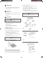
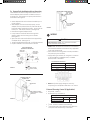
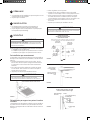
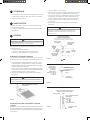
PE Dimming Control (If Applicable): • • • No external connections for Dimming are required when the GE Dimming PE Control and GE Dimming PE Receptacle is used. All dimming control connections will be made between the Dimming PE and Luminaire through the included PE Receptacle. Refer to instructions included with GE Dimming PE Control regarding appropriate settings for dimming control. PHOTOELECTRIC CONTROL: • (If option present)—Photoelectric control receptacle should be oriented before control is installed. • Loosen the two holding screws and rotate receptacle until “North” is directed as near as possible to true North. • Tighten h olding screws and install control. CAUTION Ensure the PE socket base gasket is properly seated in the die casting hole before tightening the holding screws. SLIPFITTER MOUNTING: • Connect Luminaire wire leads to supply wire. • Connections are to be made in interior of pole. • Replace pole cap. A wiring diagram is provided on a label inside luminaire for reference. • For slipfitter units without leads, connections may be made to terminal board inside fixture. • Note that care should be exercised not to pinch leads between door and housing when closing the door. 5 MAINTENANCE / CLEANING WARNING Risk of electric shock. Make certain power is off before attempting any maintenance. • • • • To maintain high optical efficiency, occasional cleaning of the outer lens surface may be needed, with frequency dependent on local conditions. Use a mild soap or d etergent, which is essentially neutral pH (pH a pproximately 6 to 8), n onabrasive, and which c ontains no chlorinated or aromatic hydrocarbons. Wash t horoughly, using a soft cloth. Rinse with clean, cold water and wipe dry. 6 STORAGE • Prior to installation, units should NOT be stored outside in c orrugated boxes (cardboard boxes) alone. • Until installation, all units should be placed in a covered dry storage area. The storage area should not exceed -40°C (-40°F) to 50°C (122°F). - This can be preferably in a roofed area or with a tarp that is secured in such a way to keep water off of the corrugated boxes (cardboard boxes). ARM MOUNTINGS: • Terminal Board is in the Architectural Mounting Arm. • Open mounting arm door to gain access to t erminal board. • Wire supply leads to terminal board in accordance with labeling. • Close door when wiring is complete. These instructions do not purport to cover all details or variations in equipment nor to provide for every possible contingency to be met in connection with installation, operation or maintenance. Should further information be desired or should particular problems arise which are not covered sufficiently for the purchaser’s purposes, the matter should be referred to GE Lighting. g GE Lighting • 1-888-MY-GE-LED (1 - 888 - 69 - 43 - 533) • www.gelighting.com GE Lighting is a subsidiary of the General Electric Company. Evolve and the GE brand and logo are trademarks of the General Electric Company. © 2013 GE Lighting. Information provided is subject to change without notice. All values are design or typical values when measured under laboratory conditions. 35-201578-198 (Rev 09/17/13) English