1
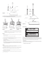
Screws
6 Inches
(152 mm)
Hub
Set Screw
Gasket
Figure 6
10 Inches
(254 mm)
Cover
Bird Shield
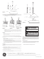
D. Luminaires with primary disconnects (outlet box hanging hardware Figure 7, rigid pendant
hardware Figure 8 and flexible pendant hanging hardware Figure 9)
1. Remove cover plate(s) and attach hanging hardware to pendant/conduit and tighten set screw.
Wireform
Cover
Figure 10
MAINTENANCE
Figure 7
2.
3.
Figure 8
Figure 9
Feed supply wire through conduit and into disconnect housing. Make necessary wire connections.
Slide the extrusion attached to the luminaire completely into the hanger extrusion. Replace
cover plate.
(Cover plate is necessary to lock luminaire into place on the hardware, cover electrical
connections and, if so equipped, seal unit from water.)
WIRING
Make all electrical connections in accordance with the National Electrical Code and any applicable
local code requirements.
Verify that supply voltage is correct by comparing it to nameplate.
For Rigid Pendant and Flexible Pendant mounting, customer’s supply connections must be above the
Nomex Wire Shield (Reference: B. Rigid Pendant Mounting, Note 2 and 5.)
IF SINGLE VOLTAGE – All single voltage/wattage ballasts are pre-wired such that user need only
connect supply conductors.
IF MULTIVOLT – (120/208/240/277) Units are pre-wired for 277. To change voltage of unit to a voltage
other 277 volts:
Disconnect incoming power lead from 277-volt ballast lead. Insulate the end of the 277-volt
ballast lead. Reconnect incoming power lead to the ballast lead marked with the correct voltage.
Incoming power lead should be stripped back 3/8” and firmly inserted in the plastic termination block
on the desired voltage ballast lead.
LAMPS
Use only lamps specified on nameplate. Observe lamp manufacturer’s recommendations and
restrictions on lamp operation, particularly ballast type, burning position, etc.
Lamp Tightness- Mogul Base Lamp: Lamp should be securely inserted to the NEMA-EEI specified
torque of 35 inch-pounds, which is best achieved by very firmly tightening to insure application of sufficient
torque.
Tightening must be sufficient to fully depress and load the center contact of the socket.
Lamp Tightness- Medium Base Lamp: Lamp should be tightened to a light firmness sufficient to
depress the center contact of the socket.
Switched Quartz- Units equipped for switched quartz operation will have the socket installed in the
reflector. Install quartz lamp.
CAUTION
Risk of burn
• Allow lamp/fixture to cool before handling
WARNING
Risk of burn
• Do not touch operating luminaire
Cleaning
Occasionally it will be necessary for the refractor to be cleaned to maintain appearance and light
levels. The frequency of cleaning will be dependent on the ambient dirt level and minimum light level
required. Refractor and housing should be washed with a solution of warm water and mild household
detergent, rinsed with clean water and wiped dry. Should the interior optical assembly become dirty, clean
the reflector and interior of refractor as described above. Replace gasket if damaged.
Lamp Replacement
Light output of a luminaire is also dependent on the age of the lamp. In applications where light level
is critical it may be desirable to replace lamps before the burn out. Consult lamp manufacturer’s data for
lamp replacement frequency and other safety issues.
Replace blackened lamps immediately.