1
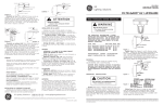
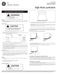
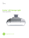
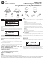
g
GE
Lighting Solutions
CONSERVA 150, 400
C1S, C4S
MPM-C
GEH-3894C
INSTRUCTIONS
Ballast and Optical Asembly for
Versaglow ®, Conserva® 150, 400 and Minimite®
MINIMITE
MMI
VERSAGLOW 150, 250
V1G V2G
MPM-3PR
MPM-3PRW
MPM-3PF
MPM-0BC
READ THOROUGHLY BEFORE INSTALLING
WARNING
Risk of electric shock
• Turn power off before servicing
– see instructions
GENERAL
The ballast assembly, optical assembly, and hanging hardware are separately packaged. Check to insure that
unit is not damaged and verify that correct material has been received.
If the luminaire you ordered has a polycarbonate refractor, please pay particular attention to the following
statement:
All polycarbonates and articles made from polycarbonates, will yellow with time. The rate of yellowing is
determined by the specific material, any additives and coatings, as well as the optical temperature and exposure to
ultraviolet (UV) light.
This yellowing can reduce the light output and impact resistance of products made from polycarbonates. In no
case should the maximum voltage recommendations listed for the luminaire be exceeded. Contact factory for more
information.
MOUNTING
CAUTION
Unit will fall if not installed properly
• Follow installation instructions
TO ATTACH LUMINAIRE TO SURFACE MOUNTED HANGING HARDWARE MPM-C
Remove wiring compartment cover plate from hanging hardware. Slide luminaire extrusion fully into hanger
extrusion. Replace cover plate. The cover plate is necessary to seal wiring chamber and lock luminaire into hanging
hardware.
TO ATTACH LUMINAIRE TO RIGID CONDUIT HANGING HARDWARE
MPM-3PRW (For Wet Location, Enclosed Minimite(MMI), Minimite(MML), and Conserva 150(C1S) only)
MPM-3PR
Remove cover plate from hanging hardware. Slide luminaire extrusion fully into hanger extrusion. Replace cover
plate. Cover plate is necessary to seal wiring chamber and lock luminaire into hanging hardware.
TO ATTACH LUMINAIRE TO NON-RIGID CONDUIT MPM-3PF
Use same assembly procedure as for above hanging hardware. If an adjustment is necessary to center weight
of luminaire in non-rigid pendant mounting, slightly loosen top screw and slide hub in relation to luminaire until
luminaire hangs vertically. Re tighten top screw.
TO ATTACH LUMINAIRE TO JUNCTION BOX MOUNTED HANGING HARDWARE MPM-OBC
Slide luminaire extrusion full into hanger extrusion. When extrusions are properly engaged, a “click’ should be
heard as spring clip rides over cast protrusion and snaps into place.
To remove luminaire, insert screwdriver blade into hole in spring clip and pull gently downward on handle, lifting
clip over cast protrusion. Grasp luminaire in both hands and withdraw it from hanger.
TO ATTACH LUMINAIRE TO WALL BRACKET MPM-WW TO WALL BRACKET
MPM-W3TFW STANCHION MOUNT MPM-5ASW
(MINIMITE OPTICALS ONLY)
Remove cover plate of mounting bracket. Slide luminaire extrusion into hanger extrusion and replace cover plate.
The cover plate is necessary to seal wiring chamber and lock luminaire into wall bracket.
INSTALLING OPTICAL ASSEMBLY
MPM-5ASW
MINIMITE
MML
MPM-W3TFW
MPM-WW
WIRING
For certain voltages, open unit through reflector plate by loosening three screws, rotating plate with a
small screwdriver in slot provided and lifting plate. (On some units, unit is opened by completely removing
screws) Wire per instructions.
Make all electrical connections in accordance with the National Electrical Code and any applicable local
coderequirements.
Verify that supply voltage is correct by comparing it to nameplate.
Do not remove insulated connectors from wires not needed for required voltage connection.
When changing voltage on reconnectable units, move only the lead with the insulated connector.
IF SINGLE VOLTAGE:
All single voltage ballasts are pre-wired such that user need only connect the supply conductors.
IF MULTIVOLT: (120/208/240/277 volts)
Connect the ballast lead with the insulated terminal to the desired voltage terminal as indicated on the
ballast terminal nameplate.
IF MULTIWATT:
Multiwatt ballasts are available in various combinations of wattage. See wiring instructions on wiring tag
inside the luminaire.
Replace reflector plate by reversing above procedure.
Note: Recessed area of plate must close off area around socket. Do not flip over when reinstalling.)
Note: For multivolt on switched quartz units, replace reflector plate with starred hole above capacitor.
LAMP INSTALLATION
Use only lamps specified on nameplate. Observe lamp manufacturer’s recommendations and restrictions on lamp operation, particularly ballast type, burning position, etc.
Lamp Tightness: The lamp should be securely inserted to NEMA-EEI Specified torque or 35 inch-pounds,
which is best achieved by very firmly tightening to insure application of sufficient torque. Tightening must be
sufficient to fully depress and load center contact of socket.
Lamp Tightness – Medium Base Lamp: The lamp should be tightened to a light firmness sufficient to
depress the center contact.
SWITCHED QUARTZ
The switched quartz socket is secured for shipping inside main lamp socket. Remove, align and snap into
starred hole provided in reflector plate. Install quartz lamp (not provided). When reflector plate is removed for
multivolt units replace with starred hole above capacitor.
MAINTENANCE AND CLEANING
CAUTION
Risk of burn
• Allow lamp/fixture to cool before handling
It will occasionally be necessary to clean outside of refractor to maintain light levels. Frequency of
cleaning will depend on ambient dirt level and minimum light levels acceptable to user. The refractor should
be washed in a solution of warm water and any mild, non-abrasive household detergent. Wipe with soft cloth
or brush. Rinse in cool, clear water. Should the optical assembly become dirty on inside, clean in above manner,
and replace any damaged gasket. Use of abrasive cleaners will shorten life of refractor and refractor.
The light output of a luminaire is also dependent on age of lamp. In applications where light level is critical
it may be desirable to replace lamps before they burn out. The lamp manufacturer can provide data showing
how lamp light output decreases with use.
NOTE: For units with clampbands, assemble refractor and reflector with clampband and hardware provided.
CAUTION: DO NOT REST A COMPLETE LUMINAIRE ON THE REFRACTOR. THIS REFRACTOR IS A PRECISION
OPTICAL INSTRUMENT AND WILL NOT SUPPORT THE FULL WEIGHT OF THE LUMINAIRE.
VERSAGLOW 150, 250, CONSERVA 150, 400
After hanging hardware, ballast assembly, and lamp have been properly installed according to their instructions,
hook latches on ballast assembly to tabs on optical assembly. Snap retaining latches to upward position to complete
installation.
MINIMITE,
After hanging hardware, ballast assembly, and lamp have been properly installed according to their instructions,
pull down three latches and slip spring loops over hooks. In the case of hook, which acts as a hinge, the flat spring must
be bent slightly to allow loop to be released.
These instructions do not purport to cover all details or variations in equipment nor to provide for every possible contingency to be met in connection with installation, operation or maintenance. Should
further information be desired or should particular problems arise which are not covered sufficiently for the purchaser’s purposes, the matter should be referred to GE Lighting Solutions.
g
GE Lighting Solutions • 1-888-MY-GE-LED • www.gelightingsolutions.com
1-88 8 - 6 9 - 4 3 -5 3 3
GE Lighting Solutions is a subsidiary of the General Electric Company. Evolve and other trademarks belong to GE Lighting Solutions. The GE brand and logo are trademarks of the General Electric Company.
© 2011 GE Lighting Solutions. Information provided is subject to change without notice. All values are design or typical values when measured under laboratory conditions.
35-201578-C4 (1/00)