1
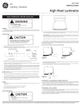
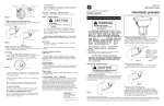
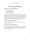
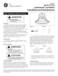
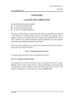
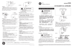
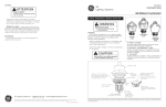
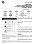
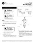
g
GEH-3792D
GE
Lighting Solutions
INSTRUCTIONS
FILTR•GARD LUMINAIRE
®
READ THOROUGHLY BEFORE INSTALLING
WARNING
Risk of electric shock
• Turn power off before servicing
– see instructions
THE OPERATING TEMPERATURE “T-CODE” LISTED FOR THIS
LUMINAIRE IS BASED ON THE FOLLOWING BULB SIZES.
USE OF OTHER THAN THESE MAY RESULT IN A HIGHER
OPERATING TEMPERATURE AND COULD RESULT IN A
HAZARDOUS CONDITION.
LAMP TYPE
HIGH PRESSURE SODIUM
HIGH PRESSURE SODIUM
METAL HALIDE/MERCURY
METAL HALIDE/MERCURY
WATTAGE
70,100,150
250, 400
175, 250
400
BULB SIZE
ED 23 1/2
ED 18
ED 28
ED 37
GENERAL
A complete luminaire consists of a ballast housing, optical
assembly, and a cover/mounting.
CAUTION: When installing luminaire in hazardous locations check operating temperature limits
prior to installation to insure it conforms to the
environmental temperature restrictions and NEC
classifications
MOUNTING INSTALLATION
CAUTION
Unit will fall if not installed properly
• Follow installation instructions
Pendant and Low Profile Cover (See Figure 1)
Remove wiring box door, and thread cover onto conduit.
Orient cover, seal around the conduit using approved NEC
procedures. Tighten set screw at mounting hub. Wiring should
be accomplished in accordance with accepted NEC practices.
A factory attached ground lead is provided. After wiring
replace the wiring compartment door.
Flexible Cover (See Figures 2 and 3)
Remove wiring box door. Loosen four(4) bolts holding
mounting hub to cover. Position adapter plate correctly to
balance luminaire. Use widest bolt spacing possible to secure
plate to cover. Wiring should be accomplished in accordance with accepted NEC practice. Factory attached ground
lead is provided. After wiring, replace the wiring box door.
Ceiling Cover (See Figure 4)
Using the tabs, mount cover to ceiling and remove wiring
box door. Wiring should be accomplished in accordance with
accepted NEC practices. Factory attached ground lead is
provided. After wiring, replace the wiring box door.
Wallmount Cover (See Figure 5)
Mount wiring box and pull leads. Tether is supplied to
hold arm assembly while wiring. Wiring should be accomplished in accordance with accepted NEC practices. Factory
attached ground lead is provided. After wiring, attach arm
assembly to wiring box. Do not damage gasket attached to
arm assembly. Mounting screws should be tightened in
alternate sequence.
Figure 3
Figure 1
PENDANT AND LOW PROFILE COVER
Figure 2
FLEXIBLE COVER
These instructions do not purport to cover all details or variations in equipment nor to provide for every possible contingency to be met in connection with installation, operation or
maintenance. Should further information be desired or should particular problems arise which are not covered sufficiently for the purchaser’s purposes, the matter should be referred
to GE Lighting Solutions.
Figure 4
CEILING COVER
Figure 5
WALLMOUNT COVER
Straight Stanchion Cover (See Figure 6)
Remove the wiring box door. Attach mounting arm onto
conduit. Wiring should be accomplished in accordance with
accepted NEC practices. Factory attached ground lead is
provided. After wiring, replace the wiring box door.
Angle Stanchion Cover (See Figure 7)
Remove the wiring box door. Attach mounting arm onto
conduit. Wiring should be accomplished in accordance with
accepted NEC practices. Factory attached ground lead is
provided. After wiring, replace the wiring box door.
WIRING
Make all electrical connections in accordance with the
National Electrical Code and any applicable local code
requirements.
Verify that supply voltage is correct by comparing it to
nameplate.
When changing voltage on reconnectable units, move only
the lead with the insulated connector.
IF SINGLE VOLTAGE:
All single voltage ballasts are pre-wired such that user
need only connect the supply conductors.
IF MULTIVOLT: (120/208/240/277 volts)
Connect the ballast lead with the insulated terminal to
the desired voltage terminal as indicated on the ballast
terminal nameplate.
IF MULTIWATT:
Multiwatt ballasts are available in various combinations of
wattage. See wiring instructions on wiring tag inside the
luminaire.
BALLAST HOUSING INSTALLATION
Slip ballast housing hinge pin over cover hinge. Mate
electrical connectors and swing unit shut. Tighten ballast
cover screw securely.
LAMP INSTALLATION
Figure 7
ANGLE STANCHION COVER
Lamp Tightness – Mogul Base Lamp: The lamp should be
securely inserted to the NEMA-EEI specified torque of 35 inchpounds, which is best achieved by very firmly tightening to
insure application of sufficient torque. Tightening must be
sufficient to fully depress and load the center contact of the
socket.
Lamp Tightness – Medium Base Lamp: The lamp should
be tightened to a light firmness sufficient to depress the
center contact.
OPTICALS
CAUTION: GLOBE IS TEMPERED GLASS. DO NOT SCRATCH
OR CHIP.
Attach globe by threading firmly into bottom of ballast
housing.
Industrial Reflector - Type EN or WN
Thread reflector firmly into ballast housing. Lamp may be
replaced via glass clampband assembly.
Prismatic Refractor Assembly
Type S, A, and W5
Thread adaptor firmly into ballast housing. To orient
asymmetrical glass, loosen clamping screws, turn glass and
retighten screws. To relamp, unscrew complete optical from
ballast housing.
ACCESSORIES
External Reflector
Insert mounting screws. Orient reflector to proper position
and slip over mounting screws. Turn reflector and tighten
screws securely.
Globe Guard
Insert protective guard into ballast housing and turn until
retained by detent.
FUSING
Branch circuit fusing is recommended rather than individual fusing, which may cause unecessary maintenance and
will not protect ballast.
MAINTENANCE
CAUTION
Risk of burn
• Allow lamp/fixture to cool before
handling
Use only lamps specified on nameplate. Observe lamp
manufacturer’s recommendations and restrictions on lamp
operation, particularly ballast type, burning position, etc.
g
Figure 6
STRAIGHT STANCHION COVER
It will occasionally be necessary to clean optical assembly
in order to maintain light levels.
Frequency of cleaning will depend on dirt levels in user’s
facility and minimum light levels which are acceptable to
him. Reflector should be cleaned with any suitable nonabrasive solution of water and soap or detergent. Residual
cleaning agent should be removed with clean water rinsing.
Glassware may be cleaned with any conventional glass
cleaner. If unit gets soiled on inside, it should be cleaned
and any damaged gasket or filter replaced.
GE Lighting Solutions • 1-888-MY-GE-LED • www.gelightingsolutions.com
1-88 8 - 6 9 - 4 3-5 3 3
GE Lighting Solutions is a subsidiary of the General Electric Company. Evolve and other trademarks belong to GE Lighting Solutions. The GE brand and logo are trademarks of the General Electric Company.
© 2011 GE Lighting Solutions. Information provided is subject to change without notice. All values are design or typical values when measured under laboratory conditions.
35-201578-57 (1/00)