1
e
BF100S
Silent Bath Fan User’s Guide
Item Stock Number(s): BF100S
READ AND SAVE THESE INSTRUCTIONS
Important Safety Instructions
CAUTION: The equipment covered by these instructions should be installed and serviced
only by competent personnel utilizing proper safety practices and procedures. These
instructions are written for such personnel and are not intended as a substitute for adequate
training and experience in safe procedures for this type of equipment.
Warning: Disconnect the power at service panel before beginning this installation.
Caution: To reduce the risk of fire and to properly exhaust air, be sure to duct air outside. Do
not vent exhaust air into spaces within walls or ceilings, or into attics, crawl spaces, or garages.
Acceptable for use over tub or shower when installed in a GFCI protected branch circuit.
Warning: To reduce the risk of fire or electric shock, do not use this fan with any solid-state
speed control device.
Warning: To reduce the risk of fire or electric shock or injury to persons, observe the following:
a) Use this unit only in the manner intended by the manufacturer. If you have any questions,
please contact the manufacturer.
b) Before servicing or cleaning unit, switch power to off at service panel and lock the service
disconnecting means to prevent power from being switched on accidentally. When the
service disconnecting means cannot be locked, securely fasten a prominent warning
device, such as a tag, to the service panel.
c) Do not install this fan in a ceiling thermally insulated to a value greater than R-40
d) Installation work and electrical wiring must be done by qualified, competent, trained
person(s) in accordance with all applicable codes and standards using proper safety
practices, including fire-related construction.
e) Sufficient air is needed for proper combustion and exhausting of gases through the flue
(chimney) of fuel burning equipment to prevent back drafting. Follow the heating equipment
manufacturer’s guideline and safety standards such as those published by the National
Fire Protection Agency (NFPA) and the American Society for Heating, Refrigeration, and
Air Conditioning Engineers (ASHRAE), and the local code authorities.
f) When cutting or drilling into a wall or ceiling, ALWAYS identify hidden electrical wiring
and other hidden utilities in advance, to avoid damage.
g) Ducted fans must always be vented to the outdoors.
Rev. A 4-04
Caution: For general ventilating use only. Do not use to exhaust hazardous or explosive
materials and vapors.
Warning: Do not use in kitchens.
h) NEVER place a switch where it can be reached from the tub or shower.
To ensure the best air and sound performance, it is recommended that the length of ducting
and the number of elbows be kept to a minimum, and that insulated hard ducting be used.
Larger duct sizes will reduce noise and airflow restriction.
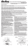
Before beginning this installation remove the fan’s
blower housing (which includes the motor, blade,
bracket and venturi) assembly by removing the screw
which secures the venturi housing to the fan housing
(Fig. 1). Place this assembly and the grill in the carton
until needed so they do not get damaged.
Mounting the Housing: New Construction
Fig. 1
Using the Hanging Brackets (refer to Fig. 2)
1. Insert the hanging brackets in the slots provided
in the housing.
2. Remove the electrical cover (which holds the fan’s
receptacle) and place it somewhere handy. Select
the most convenient electrical knockout and remove
it, then locate the fan housing between the joists
so that the bottom of the fan housing is even with
Fig. 2
the planned finished ceiling.
3. Use screws or nails (not provided) to secure the hanger bars to the ceiling joists.
Mounting the Housing: Existing Construction
1. Determine the desired location for the fan.
2. Drill a small hole through the ceiling at the chosen location and stick the end of a coat
hanger through the hole into the attic to help locate the spot in the attic.
3. Check the chosen area from above to be certain that the wiring can be installed and that
the installation will not interfere with any existing wiring. Remove the electrical
compartment cover (which holds the fan’s receptacle) and place it somewhere handy.
Select the most convenient electrical knockout and remove it.
1. Run wiring from an approved wall switch carrying the appropriate rating. One neutral
(white), one ground (green or bare copper), and one hot (black lead connected to the switch).
Secure the electrical wires to the housing with an approved electrical connector. Make
sure you leave enough wiring in the box to make the connection to the fan's receptacle.
4. From above, position the housing between ceiling joists, and use the housing as a template
to mark the required cut out in the ceiling.
2. Where you have access inside the fan’s junction box, connect the white wire from the
house to the white wire of the fan’s receptacle. Connect the black wire from the fan
switch to the black wire of the fan’s receptacle (use approved electrical connectors).
Connect the ground wire to the green ground screw in the fan’s junction box. Replace
the fan’s wire compartment cover.
5. After cutting out the required area, install the housing using the hanging brackets as
described above.
Ducting
Note: All ducting must comply with local and national building codes.
1. Connect the ducting to the fan's duct collar. Secure in place using duct tape or screw
clamp. Always duct the fan to the outside through a wall or roof cap. To ensure maximum
air delivery, keep the length of duct and number of elbows to a minimum.
Electrical Wiring
WARNING: POWER MUST BE PROVEN DISCONNECTED BEFORE STARTING INSTALLATION,
INSPECTION OR MAINTENANCE! FAILURE TO DO SO MAY CAUSE SERIOUS INJURY, DEATH
AND/OR PROPERTY DAMAGE.
Caution: Make sure power is switched off at service panel before beginning this installation.
Note: All wiring must comply with local and national codes. You must ground this unit.
Completing the Installation
1. After you have installed the housing in the ceiling,
run ducting from the unit to the outside and have
made the necessary electrical connections you can
reinstall the venturi and blower in the fan housing
(Fig. 3). Plug the fan’s blower assembly into the
fan’s receptacle and secure the blower housing
with the screw removed earlier. Rotate the blower
Fig. 3
wheel by hand to ensure it revolves freely.
2. To install the grill, squeeze the two ends of each spring fastener together and insert each
into the slots on the venturi. Push the grill up to the ceiling.
Troubleshooting Guide
Trouble
Probable Cause
Suggested Remedy
1. Fan does not operate when the switch is on.
1a. A fuse may be blown or a circuit tripped.
1b. Connector plug from motor is not plugged in.
1a. Replace fuse or reset circuit breaker.
1b. Turn off power to unit. Remove Grill and plug
motor into receptacle in housing. Restore power
to unit.
2. Fan is operating, but air moves slower than normal.
2.
2.
3. Fan is operating is louder than normal.
3a. Motor is loose.
Obstruction in the exhaust ducting.
3b. Fan blade is hitting housing of unit.
Check for any obstructions in the ducting. The
most common are bird nests in the roof cap or
wall cap where the fan exhausts to the outside.
3a. Turn off power to unit. Remove grill and check
that all screws are fully tightened. Restore
power to unit.
3b. Call your dealer for service.
Warranty
WHAT IS COVERED?
Full One Year Parts Warranty from date of original proof of purchase. We will provide, free
of charge, a replacement part that fails due to manufacturing defect in material or workmanship,
when installed and used as directed in the User’s Guide.
This warranty is extended to the original purchaser for products purchased for ordinary
home use.
WHAT IS NOT COVERED?
• Installation services or service trips to your home to teach you how to use the product.
• Labor costs or the cost of replacement components as part of routine maintenance.
• Failure or defects in product arising from Improper installation
If you have an installation problem, contact your dealer or installer. You are responsible for
providing adequate electrical, exhausting and other connecting facilities. See the Installation
Instructions provided with this product for electrical, exhaust and connection details.
• Replacement of house fuses or resetting of circuit breakers.
• Failure of the product if it is used for something other than the intended purpose of
manufacturer or used commercially.
• Damage to the product caused by accident, fire, floods, acts of customer, or acts of God.
This warranty contains the sole and exclusive warranty of GE for claims based on defects in these products. Upon the expiration of the warranty period, all such liability shall terminate.
There are no other warranties, whether written, oral, implied or statutory. NO IMPLIED STATUTORY WARRANTY OF MERCHANTABILITY OR FITNESS FOR PARTICULAR PURPOSE SHALL APPLY.
IN NO EVENT SHALL GE BE LIABLE FOR ANY SPECIAL, CONSEQUENTIAL, INDIRECT, OR INCIDENTAL DAMAGES, SUCH AS, BUT NOT LIMITED TO, LOSS OF PROFIT OR REVENUES, LOSS
OF USE OF THE PRODUCTS OR ANY ASSOCIATED EQUIPMENT, DAMAGE TO ASSOCIATED EQUIPMENT, OR COST OF SUBSTITUTE PRODUCTS.
IN NO EVENT, SHALL GE’S LIABILITY TO BUYER FROM THE SALE OF THESE PRODUCTS EXCEED THE PRICE OF THE DEFECTIVE PRODUCT SOLD AND ANY SUCH LIABILITY SHALL TERMINATE
UPON THE EXPIRATION OF THE WARRANTY PERIOD.
Read your User’s Guide. If you have any questions about operating the product, please contact your dealer.
Some states and provinces do not allow the exclusion or limitation of incidental or consequential damages and some states do not allow limitations on how long an implied warranty lasts,
so these exclusions or limitations may not apply to you. This warranty gives you specific legal rights and you may have other rights which vary from state to state and province to province.
Rev A. 4-04