1
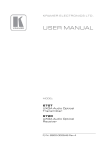
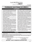
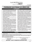
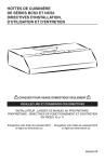
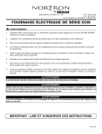
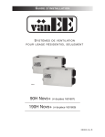
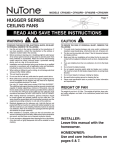
To register this product, visit www.nutone.com
READ & SAVE THESE INSTRUCTIONS!
INSTALLATION INSTRUCTIONS
Ventilation Fan
MODELS: 671R & 672R
DUCT COLLAR
COLLIER DE GAINE
COLLARÍN DE TUBO
The Exhaust Fan consists of the housing, power unit/blower
assembly (motor, wheel, mounting plate), grille and duct collar.
FAN MUST NOT BE INSTALLED IN A CEILING INSULATED
TO A VALUE GREATER THAN R-40.
HOUSING
BOITER
CUBIERTA
SUITABLE FOR USE OVER TUB OR SHOWER ENCLOSURE
WHEN INSTALLED IN A GFCI PROTECTED BRANCH
CIRCUIT.
FOR BEST RESULTS
When installing the Exhaust Fan in a new construction site,
install the housing during the rough-in construction. The blower
unit and grille should be installed after the finished ceiling is in
place.
To install the Exhaust Fan in an existing finished building, an
accessible area is required above the planned location (attic or
crawl space).
IMPORTANT SAFETY INSTRUCTIONS
WARNING: TO REDUCE THE RISK OF FIRE, ELECTRIC
SHOCK, OR INJURY TO PERSONS, OBSERVE THE
FOLLOWING:
A. Use this unit only in the manner intended by the
manufacturer. If you have questions, contact the
manufacturer.
B. Before servicing or cleaning unit, switch power off at service
panel and lock service panel to prevent power from being
switched on accidentally. When the service disconnecting means cannot be locked,
securely fasten a prominent warning device, such as a tag, to the service panel.
MOUNTING TAB
PATTES DE
MONTAGE
LENGÜETA DE
MONTAJE
SLOTS
FENTES
RANURAS
TABS
PATTES
LENGÜETA
POWER UNIT/BLOWER
ASSEMBLY
ENSEMBLE MOTEUR/
VENTILATEUR
CONJUNTO DE
UNIDAD DE POTENCIA/
SOPLADOR
CAUTION:
For general ventilating use only. Do not use to exhaust
hazardous or explosive materials and vapors. WARNING: To reduce the risk of fire or electric shock, do not
use this fan with any solid-state speed control.
INSTALLATION INSTRUCTIONS
WARNING: TO REDUCE THE RISK OF FIRE, ELECTRIC
SHOCK, OR INJURY TO PERSONS, OBSERVE THE
FOLLOWING:
A. Installation work and electrical wiring must be done by
qualified person(s) in accordance with all applicable codes
and standards, including fire-rated construction.
B. Sufficient air is needed for proper combustion and
exhausting of gases through the flue (chimney) of fuel
burning equipment to prevent back drafting. Follow the
heating equipment manufacturer’s guideline and safety
standards such as those published by the National Fire
Protection Association (NFPA), and the American Society
for Heating, Refrigeration and Air Conditioning Engineers
(ASHRAE), and the local code authorities.
GRILLE
GRILLE
REJILLA
FIGURE 1
C. When cutting or drilling into wall or ceiling, do not damage
electrical wiring and other hidden utilities.
D. Ducted fans must always be vented to the outdoors.
E. If this unit is to be installed over a tub or shower, it must be
marked as appropriate for the application and be connected
to a GFCI (Ground Fault Circuit Interrupter) protected branch
circuit.
F. NEVER place a switch where it can be reached from a tub or
shower.
PLANNING DUCTWORK AND WIRING
Ductwork
1. Use 4” round duct.
2. Plan to run duct from discharge opening of fan to the
outside. For best fan performance, make the duct run as
short as possible and use a minimum number of elbows.
3. Use optional ducting accessories as required.
Wiring
Plan to run 120vAC house wiring (with ground) from the
power source through a standard wall switch.
FLANGES
COLLERETTES
BRIDAS
Preparation
1. Refer to Figure 1. Remove blower/power unit assembly
from the housing.
(a) Unplug the power unit.
(b) Remove the screw (located next to plug-in receptacle)
which holds blower/power unit mounting plate in place. Do not misplace this screw.
(c) Lift the mounting plate at the end near the plug-in
receptacle until blower wheel clears the scroll.
(d) Remove plate by pulling its tabs out of slots in the
housing. Set blower/power unit aside until needed.
2. Remove one of the wiring knockouts from housing.
MOUNTING TAB
PATTES DE MONTAGE
LENGÜETA DE MONTAJE
WIRING KNOCKOUT
OUVERTURES
PRÉAMORCÉES
AGUJERO CIEGO DE
CABLEADO
FIGURE 2
HANGER BARS
(SOLD SEPARATELY)
BARRES DE SUSPENSION
(VENDUES SÉPARÉMENT)
BARRAS DE SUSPENSIÓN
(SE VENDEN POR SEPARADO)
MOUNTING THE HOUSING
Mounting Using Mounting Tabs
Refer to Figure 2.
1. Locate fan housing next to ceiling joist.
2. Using wood screws (not provided) loosely attach the
housing to ceiling joist through the keyhole slots in
mounting tabs.
3. Adjust housing so that it will be flush with the finished
ceiling. For the grille to fit properly, the housing’s rim must
not extend beyond finished ceiling surface.
4. When housing is properly adjusted, tighten screws in slots.
Mounting Using Hanger Bars
(hanger bars sold separately, order model HB4)
Refer to Figure 3.
1. Insert hanger bars in slots provided in housing.
2. Locate fan housing between joists so that the bottom of the
housing is even with the planned finished ceiling. Extend
the hanger bars to the joists.
3. Use screws or nails (not provided) to secure hanger bars to
ceiling joists.
DUCT COLLAR
COLLIER DE GAINE
COLLARÍN DEL TUBO
FIGURE 3
JUNCTION BOX
BOÎTE DE
JONCTION
CAJA DE
CONEXIONES
GREEN GROUND
LEAD
VIS VERTE DE MISE À
LA TERRE
HILO VERDE DE
CONEXIÓN A TIERRA
INSTALLING DUCTWORK
1. Refer to Figure 2. Place duct collar over flanges at
discharge opening of fan. Secure collar by snapping tabs
into slots in flanges.
2. Run 4” round duct from outside to fan’s discharge opening.
3. Connect duct to fan’s duct collar.
WIRING
All wiring must comply with local codes and unit must
be properly grounded.
1. Run 120vAC house wiring (with ground) from wall switch to
fan location.
2. Pull wire through access hole and into junction box.
3. Refer to Figure 4. Use approved wire nuts to connect
house supply wires to fixture as follows: white to white;
black to black. Connect green or bare ground wire to green
ground lead.
STANDARD
WALL SWITCH
(NOT INCLUDED)
INTERRUPTEUR
MURAL STANDARD
(NON INCLUS)
INTERRUPTOR DE
PARED ESTÁNDAR
(NO SE INCLUYE)
120vAC, 60Hz HOUSE
POWER
COURANT DOMESTIQUE
120V CA, 60 Hz
ELECTRICIDAD DOMÉSTICA:
120 V CA, 60 Hz
SWITCH BOX
BOÎTE D’INTERRUPTEUR
CAJA DEL INTERRUPTOR
FIELD GROUNDING WIRE
FIL DE MISE À LA TERRE
Hilo de conexión a tierra
FIGURE 4
POWER/BLOWER UNIT INSTALLATION
SLOTS
FENTES
RANURAS
1. Place power/blower unit into housing so that mounting
plate’s tabs insert into slots in housing.
2. Press other end of mounting plate down until it is firmly
seated over scroll and plug-in receptacles.
3. Secure mounting plate to housing with provided screw.
4. Refer to Figure 5. Insert motor plug into junction box
receptacle.
GRILLE INSTALLATION
MOUNTING
SPRINGS
RESSORTS
DE
MONTAGE
RESORTES
DE MONTAJE
1. Refer to Figure 6. Squeezing grille’s mounting springs
together, insert springs into slots on both sides of the
housing.
2. Press grille firmly into place against ceiling.
INSTALLATION IN EXISTING
CONSTRUCTION
Note: Installation in a finished house requires at least a small
accessible area (attic or crawl space) above the planned
installation location.
1. After determining desired location for fan, drill a small hole
in the ceiling. Place a coat hanger or other stiff wire up
through hole to help in locating from above.
2. Place fan housing on top of ceiling surface and use the
housing as a template to mark area to be cut out.
3. After cutting out opening, mount housing in the opening
using the hanger bars (sold separately), or mount directly
to joist using mounting tabs.
A. Insert hanger bars in slots in housing.
B. Position housing in opening so that bottom of
housing is flush with ceiling.
C. Use screws or nails (not provided) to secure
hanger bars to ceiling joists.
D. Complete installation as described above.
INSERT TABS
INTO SLOTS
INSÉRER LES PATTES
DANS LES FENTES
INSERTAR LENGÜETAS
EN LAS RANURAS
FIGURE 5
GRILLE
GRILLE
REJILLA
FIGURE 6
WARRANTY
One Year Limited Warranty
WARRANTY OWNER: Broan-NuTone warrants to the original consumer purchaser of its products that such products will be free from defects in materials or workmanship for a period of
one (1) year from the date of original purchase. THERE ARE NO OTHER WARRANTIES, EXPRESS OR IMPLIED, INCLUDING, BUT NOT LIMITED TO, IMPLIED WARRANTIES OF
MERCHANTABILITY OR FITNESS FOR A PARTICULAR PURPOSE.
During this one year period, Broan-NuTone will, at its option, repair or replace, without charge, any product or part which is found to be defective under normal use and service. THIS
WARRANTY DOES NOT EXTEND TO FLUORESCENT LAMP STARTERS OR TUBES, FILTERS, DUCT, ROOF CAPS, WALL CAPS AND OTHER ACCESSORIES FOR DUCTING. This
warranty does not cover (a) normal maintenance and service or (b) any products or parts which have been subject to misuse, negligence, accident, improper maintenance or repair (other than
by Broan-NuTone), faulty installation or installation contrary to recommended installation instructions.
The duration of any implied warranty is limited to the one year period as specified for the express warranty. Some states do not allow limitation on how long an implied warranty lasts, so the
above limitation may not apply to you.
Broan-NuTone’S OBLIGATION TO REPAIR OR REPLACE, AT Broan-NuTone’S OPTION, SHALL BE THE PURCHASER’S SOLE AND EXCLUSIVE REMEDY UNDER THIS
WARRANTY. Broan-NuTone SHALL NOT BE LIABLE FOR INCIDENTAL, CONSEQUENTIAL OR SPECIAL DAMAGES ARISING OUT OF OR IN CONNECTION WITH PRODUCT
USE OR PERFORMANCE. Some states do not allow the exclusion or limitation of incidental or consequential damages, so the above limitation or exclusion may not apply to you. This warranty
gives you specific legal rights, and you may also have other rights, which vary from state to state. This warranty supersedes all prior warranties.
WARRANTY SERVICE: To qualify for warranty service, you must (a) notify Broan-NuTone at the address or telephone number below, (b) give the model number and part
identification and (c) describe the nature of any defect in the product or part. At the time of requesting warranty service, you must present evidence of the original purchase date.
Date of Installation
Builder or Installer
Model No. and Product Description
IF YOU NEED ASSISTANCE OR SERVICE - CONTACT:
Broan-NuTone LLC Hartford, Wisconsin www.nutone.com 888-336-3948
Broan-NuTone Canada Mississauga, Ontario www.nutone.ca 877-896-1119
Rev. 08/2007
SERVICE PARTS
Models 671R & 672R
6
9
5
7
4
2
8
1
10
3
KEY NO.
PART NO.
1101255-000
2
32787-000
3
32788-000
4100600-000
100599-000
5100603-000
6
30652-000
754714-000
897017607
999270982
1097017708
97017709
DESCRIPTION
MOTOR MOUNTING PLATE
MOTOR ISOLATION MOUNT
GROUND CLIP
MOTOR (671R)
MOTOR (672R)
BLOWER WHEEL
DUCT ADAPTER ASSEMBLY
GRILLE SPRING (2 REQ.)
GRILLE ASSEMBLY (INCLUDES GRILLE SPRINGS)
RECEPTACLE
POWER UNIT ASSEMBLY (671R)
POWER UNIT ASSEMBLY (672R)
Broan-NuTone LLC Hartford, Wisconsin www.nutone.com 888-336-3948
11
12
99044124A