1
Magnum 6KQ Managed Field Switch Installation and User Guide
(04/07)
“+ve potential”. The more “+ve” voltage lead from 48V or –48V supply must
be connected to the post labeled “+”.
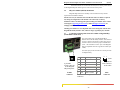
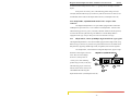
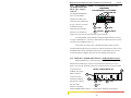
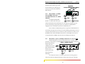
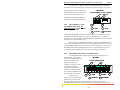
The connection procedure is straightforward. Simply connect the DC leads to
the Switch’s power terminals, positive (+) and negative (-) screws. The use of Ground
(GND) is optional; it connects to the Switch chassis. Ensure that each lead is securely
tightened.
C5.1 UL Requirements
The following must be adhered to in order to conform to UL requirements:
1. Minimum 18 AWG cable for connection to a Centralized DC power source.
2. Minimum 14 AWG cable for connection to earthing wiring.
3. Use only with Listed 10 A circuit breaker provided in building installation.
4. “Complies with FDA radiation performance standards, 21 CFR subchapter J.”
or equivalent.
5. Fastening torque of the lugs on the terminal block: 9 inch pound max.
6. Centralized DC Power Source cable securement, use at least four cable ties to
secure the cable to the rack at least 4 inches apart with the first one located
within 6 inches of the terminal block.
C6.0
ORDERING INFORMATION
To order the optional Dual-Source -48VDC power supply factory installed,
order “Dual-Src48V” as a separate line item following the product model.
Example: Magnum 6KQR-48VDC
Dual-Src-48V for the regular DS model
Similarly, order the “Dual –source 24VDC” or “Dual-source 125VDC” as a
separate line item following the product model.
Example: Magnum 6KQ-24VDC or Magnum P6KQ-125VDC
Dual-Src24V for regular models
Or Dual-Src125V-Switch
See the Configuration Guide on the GCI web site at
http://www.garrettcom.com/techsupport/insertion_guides/6kqcg.pdf
for additional information.
C7.0
OPERATION
Operation of the Dual-Source Magnum 6Ks-48VDC, 24VDC and 125VDC
Switch models are identical to that of the standard models.
www . GarrettCom . com
50