1
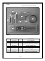
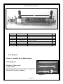
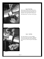
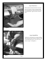
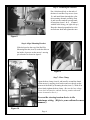
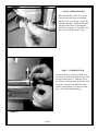
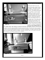
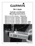
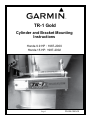
TR-1 Gold
Cylinder and Bracket Mounting
Instructions
Honda 9.9 HP : 1987-2000
Honda 15 HP: 1987-2002
Page 1
PN 906-1050-00
Parts:
Cylinder Mounting Kit PN 120-1050-00
8
3
1
2
11
9
5
12
13
4
Figure 1
ITEM
1
2
3
4
5
8
9
11
12
13
PART NUMBER
330-1051-00
130-1052-00
330-1003-00
380-1054-00
380-1056-00
310-0206-12
130-0083-00
310-2501-25
310-0067-01
310-0067-02
QTY
1
1
1
1
1
3
1
1
1
1
Page 2
DESCRIPTION
NUT, STANDOFF
BRACKET, ROD EYE MOUNTING
PIN, STERN PIVOT
CHANNEL, CYLINDER MOUNTING
PLATE, STANDOFF NUT
HEX CAP M6 X 12MM
HOSE CLAMP
CLEVIS PIN
HAIR PIN, COTTER, LARGE
HAIR PIN, COTTER, MEDIUM
Cylinder Kit PN 120-0900-00
35
38
40
34
Figure 2
31
33
34
35
36
330-1002-00
310-0042-09
340-0900-00
321-0001-00
330-1101-00
Rod Eye, 5/16-24
Hex Jam Nut 5/16-24
Cylinder
Fitting, Straight 1/8 NPT X 1/4
Zinc Anode (Replace)
1
1
1
2
1
37
38
40
310-0040-26
328-0901-00
328-0902-00
Washer, Flat, Nylon 1/4 ID X .03
Bushing 1/4 ID X 5/16 OD X 1/4”L
Cylinder Tail Bushing
1
2
1
Tools Required
Section 1. Installing the Cylinder Mounts.
Tools Required:
9/32 inch or 7mm wrench
10 mm wrench
1/2 Inch wrench (at least one needs to be open end)
Thread Lock (Loctite or similar)
Figure 3
Page 3
Step 1: Rear Nuts
Tip the motor all the way up. Remove the
two rear nuts from the lower motor port side
vibration isolation mounting shroud by loosening the screws that come in to them from
the starboard side. Leave the screws in place.
Figure 4
Step 2: Nut Plate
Put a little thread lock on the protruding
ends of the screws just loosened. Thread the
screws into non flat side of the Standoff nut
plate (item 5) as shown in figure 5 and tighten
them.
Figure 5
Page 4
Step 3: Front Screw
Remove the forward nut from the lower motor
port side vibration isolation mounting shroud
by loosening the screw that comes into it from
the starboard side. Again, leave the screws in
place.
Figure 6
Step 4: Standoff Nut
Again, put a little thread lock on the protruding
end of the screw just loosened. Thread one end
of the standoff nut (item 1) on to the screw as
shown in figure 7 and tighten it.
Figure 7
Page 5
Step 5: Mounting the Channel
Put a little thread lock on the ends of
the three 6 mm Hex Cap screws (item
11) and install them through the cylinder mounting channel assembly (item
4) and into the standoff nut and standoff nut plate (items 1 & 5). (Channel
with the label facing you right side up.)
Keep the channel perpendicular to the
motor down shaft and tighten the nuts.
Figure 8
Step 6: Align Mounting Bracket
Slide the bend on the top of the Rod Eye
Mounting Bracket (item 2) under the tube on
the inside of gussets on the motor’s steering
pivot bracket as shown in figure 9.
Figure 9
Step 7: Hose Clamp
Open the hose clamp (item 9) and install it around the shank
of the motors’s steering pivot bracket and over the tab on the
bottom of the Rod Eye mounting bracket (item 2). With all in
place firmly tighten the hose clamp. (Be sure the hose clamp
screw does not interfere with the steering rotation when the
motor is turned to steer it.)
Loosen the steering tension device to the
minimum setting. (Refer to your outboard owners
manual.)
Figure 10
Page 6
Step 8: Cylinder Rod Eye
Place the Rod Eye (item 31) over the
vertical pin in the rod eye mounting
bracket (item 2) as shown. (Leave the
cylinder attached.) Install the Medium
hair pin cotter (item 13) through the
hole in the vertical pin. Turn the cylinder (item 34) fittings (item 35) up.
Figure 12
Step 9: Cylinder End Cap
Line the hole in rear end cap of the cylinder (item 34) with the hole in the top of the
stern pivot pin (item 3). Slide the Clevis
pin (item 11) through the hole into the stern
pivot pin. Put the Large Hair Pin cotter
(item 12) through the cross holes in both
pins. (Under the channel flange).
Figure 13
Page 7
Step 10: Full Port and Starboard
Turn the motor hard over to port.
That will retract the cylinder rod into
the cylinder. Check that the cylinder
rod is still free to retract at least a
little more. Next turn the motor hard
over to starboard. That will extend
the cylinder rod out of the cylinder.
Check that the cylinder rod is still
free to extend at least a little more. It
should have additional travel in both
directions. If it does not adjust the
position of the Rod Eye (item 31) on
the cylinder shaft. The cylinder shaft
should turn with your fingers if the
Hex Jam Nut (item 33) is loose. (If
the shaft does not turn freely enough,
use a thin 1/4 Inch open end wrench at
the shaft’s wrench flats.) Do not use
Figure 14
any tool on the cylindrical part of
the cylinder shaft. If the shaft gets scratched or bent the seal will fail. With the cylinder properly
adjusted, secure it by tightening the Hex Jam Nut against the Rod Eye. (Use Thread locking compound
on the rod eye block threads and the Jam Nut.) It is ready for plumbing. We suggest you put the original
parts in a container and, carefully, store them. (You may eventually want to sell or trade in your motor;
but we know you will want to keep your TR-1 Autopilot
Figure 15
Page 8