1
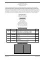
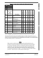
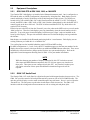
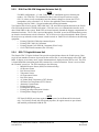
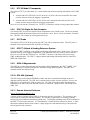
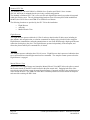
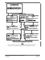
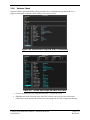
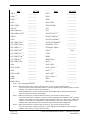
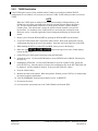
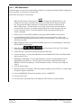
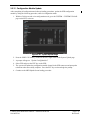
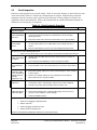
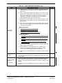
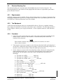
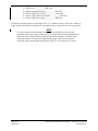
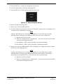
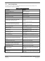
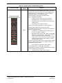
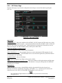
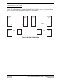
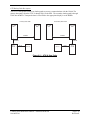
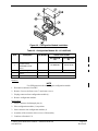
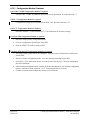
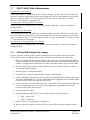
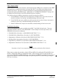
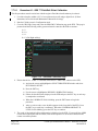
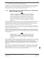
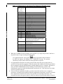
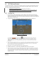
Figure 6-3. Configuration Module Installation
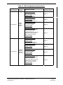
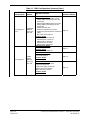
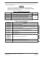
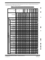
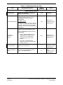
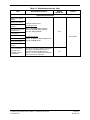
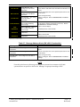
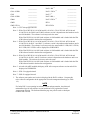
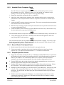
Table 6-2. Configuration Module Kit – 011-00979-00
Item
1
2
3
4
Description
Configuration Module PCB
Board Assembly
w/EEPROM & Temp
Sensor
Spacer, Config Module
Cable, 4-Conductor
Harness
Pins, #22 AWG (HD)
Qty Needed
Garmin Part Number
011-00979-00
Kit
011-00979-03
Kit
012-00605-00
011-02178-00
213-00043-00
N/A
1
1
1
5
325-00122-00
336-00021-00
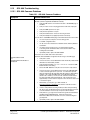
Removal:
NOTE
Use ESD protection when handling the configuration module.
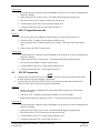
1. Disconnect connector from LRU.
2. Remove 2 screws (8) from cover (7) and remove cover.
3. Unplug connector from configuration module (1).
4. Remove configuration module.
Replacement:
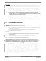
1. Inspect connector for damaged pins (4).
2. Place configuration module (1) in position.
3. Insert connector into configuration module (1).
4. Assembly of the connector is the reverse of disassembly.
5. Continue to Section 6.12.1.
G1000 System Maintenance Manual – Diamond DA40/40F
190-00545-01
Page 6-9
Revision G