1
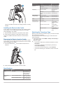
• To avoid interference with a magnetic compass, the device should not be installed closer to a compass than the compass-safe distance value listed in the product specifications. echo™ Installation Instructions Installing the Swivel Base Important Safety Information Preparing to Run Cables under the Mounting Surface WARNING See the Important Safety and Product Information guide in the product box for product warnings and other important information. NOTICE Use pan-head screws or bolts when securing the swivel-mount base. Screws or bolts with countersunk heads damage the base. CAUTION Always wear safety goggles, ear protection, and a dust mask when drilling, cutting, or sanding. NOTICE When drilling or cutting, always check what is on the opposite side of the surface. Before you can prepare the swivel-mount base, you must choose the location to install the mount and decide whether to attach the mount using screws or bolts. 1 Remove the 10 mm M6x1 Phillips screw À and separate the swivel mount Á from the base Â. Registering Your Device Help us better support you by completing our online registration today. • Go to http://my.garmin.com. • Keep the original sales receipt, or a photocopy, in a safe place. Contacting Garmin Product Support • Go to www.garmin.com/support and click Contact Support for in-country support information. • In the USA, call (913) 397.8200 or (800) 800.1020. • In the UK, call 0808 2380000. • In Europe, call +44 (0) 870.8501241. desired direction. Tools Needed • • • • • • 2 Orient the swivel base so the pass-through holes à face the Drill and drill bits #2 Phillips screwdriver Marine sealant 3/ in. wrench or socket 8 Masking tape Hardware for the swivel mount (not included) ◦ Self-tapping, pan-head wood screws or pan-head bolts, either size #8 or a diameter of 5/32 in. (4 mm) ◦ Appropriate washers and nuts (if selecting bolts) ◦ Appropriate drill bit for drilling the pilot hole 3 Using the swivel base as a template, mark the pilot hole locations Ä. 4 Mark the cable routing hole Å. Mounting Considerations The fishfinder device can be mounted using the included swivelmount bracket, or it can be mounted flush with the dashboard using the appropriate flush-mount kit (sold separately). Before permanently installing any part of your device, you should plan the installation by determining the location of the various components. • The mounting location must provide a clear view of the screen and access to the keys on the device. • The mounting location must be sturdy enough to support the device and the mount. • The cables must be long enough to connect the components to each other and to power. • The cables can be routed under the swivel mount or behind the device. November 2013 5 Using the appropriate drill bit for the hardware, drill the three pilot holes. 6 Using a 5/8 in. (16 mm) drill, drill a hole through the mounting surface at the location you marked in step 4. Fastening the Swivel Mount without the Cables Running through the Mount You should complete this procedure only if you are not running the power and transducer cables under the mounting surface and through the swivel-mount base. 190-01708-02_0A Printed in Taiwan 1 Place the base À on the mounting surface, and fasten it using the appropriate screws or bolts Á. 2 Place the swivel mount on the base, and replace the 10 mm M6×1 Phillips screw. 3 Seal the cable pass-through holes with marine sealant. Fastening the Swivel Mount with the Cables Running through the Mount You should complete this procedure only if you are running the power and transducer cables under the mounting surface and through the swivel-mount base. 1 Feed the cables through the 5/8 in. (16 mm) center hole you drilled when preparing to run cables beneath the mounting surface. 2 Place the base on the mounting surface, and fasten it using the appropriate screws or bolts. 3 Route the cables through the cable pass-through holes. 4 Loosely fasten the base using the appropriate screws or bolts. 5 Place the swivel mount on the base, but do not fasten it. 6 Place the cradle or device into the swivel mount (Installing the Device in the Cradle). 7 Pull out enough slack from the power and transducer cables so the mount can fully swivel to the desired positions when the cables are connected. 8 Remove the cradle and the swivel mount from the base. 9 Apply marine sealant to the 5/8 in. (16 mm) center hole and to the cable pass-through holes. 10 Securely fasten the base with the appropriate screws or bolts. 11 Place the swivel mount on the base, and fasten it using the included 10 mm M6×1 Phillips screw. Installing the Device in the Swivel Mount If your device uses a cradle, you must install the cradle into the swivel mount. If your device does not use a cradle, you must install the device into the swivel mount. 1 Pull up the locking arm À. 2 Place the cradle or device into the swivel mount Á. 3 Tilt the mount to the desired viewing angle. 4 Press down the locking arm. Installing the Cables and Connectors Wiring to Power 1 Route the power cable from the swivel mount to the boat battery or fuse block. 2 If necessary, extend the wires using 20 AWG or larger wire. 3 Connect the red wire to the positive terminal on the battery or fuse block, and connect the black wire to the negative terminal. Connecting the Device to a Transducer NOTE: The device goes into simulator mode if the connection is not secure between the device and transducer. Go to www.garmin.com or contact your local Garmin® dealer to determine the appropriate type of transducer for your needs. 1 Follow the instructions provided with your transducer to correctly install it on your boat. 2 Route the transducer cable to the back of your device, away from sources of electrical interference. 3 Connect the transducer cable to the appropriate port on your device. Connecting the Cables to the Device The connectors on the cables are keyed to fit only in the correct ports on the device or cradle. For devices that use the mounting cradle, the connected cables are held in place by a locking bracket. For devices that do not use a mounting cradle, the cables connect directly to the device. 1 Compare the divots À on each cable connector to the keying on each port to determine which cable corresponds to each port. 2 Securely connect each cable to a port. 3 For devices that require the cradle, place the locking bracket Á over the cables and slide the bracket down to lock the cables in place. 2 Specification Models Measurement Compass-Safe Distance echo 101, 151, and 201 10 in. (250 mm) echo 301c 13.8 in. (350 mm) echo 501c and 551c 15.75 in. (400 mm) echo dv models 50/77/200 kHz, DownVü echo 101 200 kHz Frequency echo 151, 201, 301, and 501 50/77/200 kHz series There is an audible click when the locking bracket is correctly installed. Installing the Device in the Cradle If your device uses a cradle and you have connected the cables to the cradle, you can quickly place the device in the cradle without plugging in any cables. 1 Place the base of the device in the bottom of the cradle. 2 Tilt the device toward the cradle until it fastens in place. There is an audible click when the device is secured in the cradle. Removing the Device from the Cradle If your device uses a cradle and you have connected the cables to the cradle, you can quickly remove the device from the cradle without unplugging any cables. 1 Press the release lever À on the cradle until the device is released. Power Source Voltage Range echo 101 series from 10 to 20 V echo 201, 301, and 501 series from 10 to 28 V Fuse All models AGC/3AG - 3.0 A Rated Current All models 1 A Transmit Power echo 101 series 200 W (RMS), 1,600 W (peak-topeak) echo 201 and 301 series 300 W (RMS), 2,400 W (peak-topeak) echo 501 series 500 W (RMS), 4,000 W (peak-topeak) Selecting the Transducer Type Before you can select the transducer type, you must know what kind of transducer you have. You may need to set the transducer type to make the sonar function properly. 1 From a sonar view, select MENU > Setup > Sonar Setup > Transducer Type. 2 Select an option: • If you have a 200/77 kHz, dual-beam transducer, select Dual Beam. • If you have a 200/50 kHz dual-frequency transducer, select Dual Frequency. • If you have a DownVü transducer, select DownVü. • If you have another type of transducer, select it from the list. 2 Tilt the device forward, and lift it out of the cradle. Specifications Specification Models Measurement Case All models Fully gasketed, high-impact plastic, water resistant to IEC 60529 IPX7 Temperature Range echo 101 and 201 series From 5° to 158°F (from -15° to 70°C) echo 301 and 501 series From 5° to 131°F (from -15° to 55°C) 3 Garmin® and the Garmin logo are trademarks of Garmin Ltd. or its subsidiaries, registered in the USA and other countries. echo™ is a trademark of Garmin Ltd. or its subsidiaries. These trademarks may not be used without the express permission of Garmin. Garmin International, Inc. 1200 East 151st Street Olathe, Kansas 66062, USA Garmin (Europe) Ltd. Liberty House, Hounsdown Business Park Southampton, Hampshire, SO40 9LR UK Garmin Corporation No. 68, Zhangshu 2nd Road, Xizhi Dist. New Taipei City, 221, Taiwan (R.O.C.) © 2013 Garmin Ltd. or its subsidiaries www.garmin.com/support