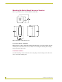
1
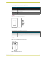
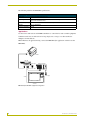
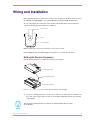
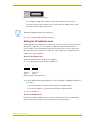
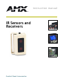
instruction manual
IR Sensors and
Receivers
C on t ro l Pa n el A c c e s s o rie s
AMX Limited Warranty and Disclaimer
AMX Corporation warrants its products to be free of defects in material and workmanship under normal use for
three (3) years from the date of purchase from AMX Corporation, with the following exceptions:
•
Electroluminescent and LCD Control Panels are warranted for three (3) years, except for the display and touch
overlay components that are warranted for a period of one (1) year.
•
Disk drive mechanisms, pan/tilt heads, power supplies, MX Series products, and KC Series products are
warranted for a period of one (1) year.
•
Unless otherwise specified, OEM and custom products are warranted for a period of one (1) year.
•
Software is warranted for a period of ninety (90) days.
•
Batteries and incandescent lamps are not covered under the warranty.
This warranty extends only to products purchased directly from AMX Corporation or an Authorized AMX Dealer.
AMX Corporation is not liable for any damages caused by its products or for the failure of its products to perform.
This includes any lost profits, lost savings, incidental damages, or consequential damages. AMX Corporation is not
liable for any claim made by a third party or by an AMX Dealer for a third party.
This limitation of liability applies whether damages are sought, or a claim is made, under this warranty or as a tort
claim (including negligence and strict product liability), a contract claim, or any other claim. This limitation of
liability cannot be waived or amended by any person. This limitation of liability will be effective even if AMX
Corporation or an authorized representative of AMX Corporation has been advised of the possibility of any such
damages. This limitation of liability, however, will not apply to claims for personal injury.
Some states do not allow a limitation of how long an implied warranty last. Some states do not allow the limitation or
exclusion of incidental or consequential damages for consumer products. In such states, the limitation or exclusion of
the Limited Warranty may not apply. This Limited Warranty gives the owner specific legal rights. The owner may
also have other rights that vary from state to state. The owner is advised to consult applicable state laws for full
determination of rights.
EXCEPT AS EXPRESSLY SET FORTH IN THIS WARRANTY, AMX CORPORATION MAKES NO
OTHER WARRANTIES, EXPRESSED OR IMPLIED, INCLUDING ANY IMPLIED WARRANTIES OF
MERCHANTABILITY OR FITNESS FOR A PARTICULAR PURPOSE. AMX CORPORATION
EXPRESSLY DISCLAIMS ALL WARRANTIES NOT STATED IN THIS LIMITED WARRANTY. ANY
IMPLIED WARRANTIES THAT MAY BE IMPOSED BY LAW ARE LIMITED TO THE TERMS OF THIS
LIMITED WARRANTY.
Table of Contents
Table of Contents
Product Information .................................................................................................1
Features ............................................................................................................................ 1
Specifications: Sensors and Receivers ............................................................................. 2
AXD-IR+ ................................................................................................................................... 2
AXR-IRSM+ ............................................................................................................................. 2
IRX-DM+ .................................................................................................................................. 3
IRX-SM+ .................................................................................................................................. 3
Applications.............................................................................................................................. 4
Wiring and Installation .............................................................................................7
Setting the Receive Frequency ......................................................................................... 7
Configuring the Receivers ................................................................................................. 8
Setting the AXlink Device Number ........................................................................................... 8
Setting the IR Validation Level .......................................................................................... 9
Receiver IR validation level...................................................................................................... 9
Sensor IR validation level......................................................................................................... 9
Wiring the IR Sensors and Receivers ............................................................................. 10
Preparing captive wires.......................................................................................................... 10
Wiring guidelines.................................................................................................................... 10
Connecting the Wiring ..................................................................................................... 11
Wiring the AXD-IR+ or the AXR-IRSM+ to AXlink.................................................................. 11
Using the AXlink four-pin connector with an external 12 VDC power supply......................... 11
Wiring the IRX-DM+ or IRX-SM+ to the AMX IR Receiver..................................................... 12
Checking IR Data status ........................................................................................................ 12
Checking AXlink status .......................................................................................................... 12
Mounting the UniMount Sensor or Receiver ................................................................... 13
Mounting the Swivel-Mount Sensor or Receiver ............................................................. 14
Installation method A.............................................................................................................. 14
Installation method B.............................................................................................................. 15
IR Sensors and Receivers
i
Table of Contents
ii
IR Sensors and Receivers
Product Information
Product Information
The AMX infrared (IR) sensors and receivers (AXD-IR+, AXR-IRSM+, IRX-DM+, and IRXSM+) work with AMX IR-format 38 or 455 kHz wireless transmitters.
The AXD-IR+ and AXR-IRSM+ are remote IR receivers used with AMX Axcess Central
Controllers and operate via the AXlink bus to remotely control AXlink devices. The AXD-IR+ is in
a UniMount wall panel that fits into most US-style single-gang enclosures. The AXR-IRSM+ is in
a swivel-mount enclosure for wall or ceiling installations.
The IRX-DM+ and IRX-SM+ are remote IR sensors that work with the Axcess
AXC-RCVI card, AMX Television Managers, and MX8 and MX16 Relay Receivers to remotely
control IR devices. The IRX-DM+ is in a UniMount enclosure and the IRX-SM+ is in a swivelmount enclosure.
Behind the IR window on each of the four units is a red IR data LED. The LED is on when the IR
sensor on the unit receives IR data from a transmitter (see FIG. 1).
IR Sensor
IR Data LED
FIG. 1 Swivel-mount and UniMount sensors and receivers
Features
The AXR-IRSM+ and AXD-IR+:
!
Are AXlink 38 or 455 kHz IR receivers
!
Work in AMX Axcess Central Controller
The IRS-UM+ and IRX-SM+:
!
Are remote 38 or 455 kHz IR sensors
!
Work with the Axcess AXC-RCVI card, AMX Television Managers, and MX8 and
MX16 Relay Receivers
The UniMount units mount into most US-style single-gang enclosures.
IR Sensors and Receivers
1
Product Information
The swivel-mount units:
!
Install on the ceiling or wall, and can be positioned horizontally or vertically
!
Swivel for best IR reception and protection from fluorescent interference
Specifications: Sensors and Receivers
AXD-IR+
FIG. 2 shows the AXD-IR+ Decor IR receiver.
FIG. 2 AXD-IR+ Decor IR receiver
The following table lists the AXD-IR+ specifications:
AXD-IR+ Specifications
Mounting:
Mounts into most US-style single-gang enclosures.
Dimensions (HWD):
4.5" x 3.18" x 1.80" (114 mm x 80 mm x 45.8 mm)
1.50" (38 mm) depth from wall surface
Weight:
7.8 oz. (218.4 g)
Power Consumption: 35 mA
AXR-IRSM+
FIG. 3 shows the AXR-IRSM+ swivel-mount IR receiver.
FIG. 3 AXR-IRSM+ swivel-mount IR receiver
2
IR Sensors and Receivers
Product Information
The following table lists the AXR-IRSM+ specifications.
AXR-IRSM+ Specifications
Enclosure
Neutral off-white metal enclosure
Mounting
May be used without the wall bracket for flush mounting. Comes with full set of mounting screws and wall anchors.
Dimensions (HWD)
2.0" x 3.3" x 2.6" (51 mm x 84 mm x 66 mm)
Weight
5.6 oz. (174 grams)
Power Consumption
35 mA
IRX-DM+
FIG. 4 shows the IRX-DM+ Decor IR sensor.
FIG. 4 IRX-DM+ Decor IR sensor
The following table lists the IRX-DM+ specifications.
IRX-DM+ Specifications
Mounting
Mounts into most US-style single-gang enclosures.
Dimension (HWD)
4.5" x 3.18" x 1.5" (114 mm x 80.8 mm x 38 mm) 1.05" (26.7) depth from wall surface
Weight
6.8 oz. (190.4 grams)
Power Consumption
25 mA
IRX-SM+
FIG. 5 shows the IRX-SM+ swivel-mount IR sensor.
FIG. 5 IRX-SM+ swivel-mount IR sensor
IR Sensors and Receivers
3
Product Information
The following table lists the IRX-SM+ specifications:.
IRX-SM+ Specifications
Enclosure
Neutral off-white metal enclosure
Mounting
May be used without the wall bracket for flush mounting. Comes with full set of mounting screws and wall anchors.
Dimensions (HWD)
2.0" x 3.3" x 2.6" (51 mm x 84 mm x 66 mm)
Weight
4.8 oz. (149 grams)
Power Consumption
25 mA
Applications
Use the sensors and receivers with AMX transmitters to control devices such as media equipment.
Combine several sensors and receivers for large single-area coverage or as discrete units for
multiple room installations.
FIG. 6 illustrates an application using a sensor, the IRX-SM+ (the application could also use the
IRX-DM+).
IRX-SM+
AXB-TMX
Power supply
AXCESS CardFrame
AXlink
Power supply
CC-IRC
Television
FIG. 6 Sample IRX-SM+ equipment configuration
4
IR Sensors and Receivers
Product Information
FIG. 7 illustrates an application using a receiver, the AXD-IR+ (the application could also use the
AXR-IRSM+).
AXD-IR+
AXlink
AXCESS CardFrame
Controlled devices
FIG. 7 Example equipment configuration using the AXD-IR+
IR Sensors and Receivers
5
Product Information
6
IR Sensors and Receivers
Wiring and Installation
Wiring and Installation
Before installing the sensors and receivers, set the receive frequency on the units. On the receivers,
the AXD-IR+ and AXR-IRSM+, also set the AXlink device number and IR validation level.
To access the jumper pins or switches on the circuit board assembly in the swivel mount units,
separate the housing from the swivel base (see FIG. 8).
Swivel mount base
Housing
Circuit board assembly
FIG. 8 Separating the housing from the swivel base on the swivel mount units
On the UniMount units, the AXlink jumpers and switches are on the back of the panel.
Setting the Receive Frequency
Perform the following steps (see FIG. 9) to set the receive frequency:
Sensor circuit board assembly
Receive frequency jumper pins
Receiver circuit board assembly
FIG. 9 Receive frequency jumper pins set at the default setting for receiving 38 kHz
1. Use the set of jumper pins (one set on the sensors and two sets on the receivers-see FIG. 9) on
the corner of the circuit boards to set the receive frequency. FIG. 10 illustrates the positioning
of the jumpers.
The unit will not operate with one set of pins set for 38 kHz and the other set of pins
set for 455 kHz.
IR Sensors and Receivers
7
Wiring and Installation
!
To receive 455 kHz, position the jumper (both jumpers on the receivers) on the left two
pins, pins 1 and 2, away from the edge of the circuit boards, to receive 455 kHz. (This is
the default setting.)
!
To receive 38 kHz, position the jumper (both jumpers on the receivers) on the right two
pins, pins 2 and 3, near the edge of the circuit boards, to receive 38 kHz.
IR SNSR
38/455
kHz
IR SNSR
38/455
kHz
Setting for 455 kHz
Setting for 38 kHz (default)
FIG. 10 Receive frequency jumper settings
2. Go on to the next procedure:
!
If you are installing a receiver, go on to Configuring the Receivers.
!
If you are installing an IR sensor, refer to Sensor IR validation level in Configuring the
Receivers before going on to Installation.
Configuring the Receivers
To configure the receivers, set the AXlink device number and the IR validation level.
AXlink Device DIP switch
IR validation jumper pins
AXlink connector
FIG. 11 IR receiver AXlink device DIP switches, IR validation jumper pins, AXlink connector, and receive
frequency jumper pin locations
Setting the AXlink Device Number
Perform the following steps to set the receiver's AXlink device number:
1. Locate the eight-position Device DIP switch (FIG. 11).
2. Set the DIP switch according to the DIP switch values shown in FIG. 12.
The device number is set by the total value of DIP switch positions that are ON (down). The
Axcess software program in your system typically uses device numbers 128 through 255 for
the panels.
Switch 1 2 3 4
Value
8
5
6
7
8
1 2 4 8 16 32 64 128
IR Sensors and Receivers
Wiring and Installation
FIG. 12 DIP switch values and quick reference
As an example, the DIP switch in FIG. 12 defines device number 129 (1+128=129).
If you later change the device number, remove and reconnect the AXlink connector. This
enters the new device number into memory.
The device number takes effect only on power-up.
3. Go on to Setting the IR Validation Level below.
Setting the IR Validation Level
An IR transmitter must send repetitions of data for the receiver to accept it as valid data. In some
installations, a light wall color or other physical condition may interfere with the sensor's or
receiver's ability to sense the transmitted signal. The signal may reflect or bounce and become
distorted. The receivers can be set to use either two or three repetitions of sequential signals to
validate and accept the signal data.
Receiver IR validation level
Perform the following steps to set the receiver's IR level.
1. Locate jumper pins J1 on the circuit board (FIG. 13).
2
3
2
J1
3
J1
Setting for two
validations
Setting for three
validations
FIG. 13 IR validation jumper pin settings
2. Position the IR validation jumper (Figure 9) to select the number of valid IR data repetitions to
be accepted:
!
Position the jumper at 2 to have the unit validate two sequential signals.
!
Position the jumper at 3 to have the unit validate three sequential signals.
3. Go on to Installation.
Sensor IR validation level
For the sensors, this IR validation level is set on the receiving device (such as an AXC-RCVI).
Refer to the instruction manuals for the receiving device for more information.
IR Sensors and Receivers
9
Wiring and Installation
Wiring the IR Sensors and Receivers
The IR Sensors and Receivers use a four-pin AXlink connector for power and data. If the distance
between the panel and Central Controller exceeds power consumption limits, you can connect a
local 12 VDC power supply to the AXlink connector.
FIG. 14 shows the location of the AXlink connector on the rear panel of the IR sensors and
receivers.
Sensor circuit board assembly
AXlink connector
Receiver circuit board assembly
FIG. 14 Circuit board assemblies for IR sensors and receivers
To access the AXlink connector on the AXR-IRSM+, separate the swivel-mount base from the
housing. (Refer to Figure 4.) On the AXD-IR+, the AXlink connector is on the underside of the
unit.
Preparing captive wires
You will need a wire stripper and a flat-blade screwdriver to prepare the captive wires.
Prepare and connect the captive wires as follows.
1. Strip .25 inch (6.35 mm) of wire insulation off all wires.
2. Insert each wire into the appropriate opening on the connector according to the wiring
diagrams (following) in this section.
3. Turn the flat-head screws clockwise to secure the wire in the connector.
Do not over-torque the screw. Doing so can bend the seating pin
Wiring guidelines
The IR sensor or receiver requires 12 VDC power to operate properly. The power is supplied by the
AMX system's AXlink cable. The maximum wiring distance between the Central Controller and
the receiver or sensor is determined by power consumption, supplied voltage, and the wire gauge
used for the cable. The following table lists wire sizes and the maximum lengths allowable between
10
IR Sensors and Receivers
Wiring and Installation
the receiver or sensor and the Central Controller. The maximum wiring lengths are based on a
minimum of 13.5 volts available at the Central Controller's power supply.
Wiring Specifications
Maximum Wiring Length
Wire Size
IR Sensors
IR Receivers
18 AWG
4,696 feet (1431.34 m) 3,354 feet (1022.30 m)
20 AWG
2,970 feet (905.26 m)
2,121 feet (646.48 m)
22 AWG
1,851 feet (564.18 m)
1,314 feet (400.511 m)
24 AWG
1,167 feet (355.70 m)
833 feet (253.90 m)
If you install the IR sensor or receiver farther away from the Central Controller than recommended
in the Wiring Specifications table, connect an external 12 VDC power supply, as shown in the
wiring diagrams in this section.
Connecting the Wiring
The following paragraphs describe wiring connections using AXlink for data and power, using
AXlink plus an external 12 VDC power supply, and wiring the IRX-DM+ or IRX-SM+ to the AMX
IR receiver.
Wiring the AXD-IR+ or the AXR-IRSM+ to AXlink
Install the AXlink data/power bus wiring as shown in FIG. 15.
AXlink connector on
the AXD-IR+ or the
AXR-IRSM+
(-) GND 1
AXM 2
1 GND (-)
2 AXM
3 AXP
AXP 3
(+) PWR 4
Control system
4 PWR (+)
FIG. 15 AXlink wiring
Using the AXlink four-pin connector with an external 12 VDC power supply
Connect the Central Controller's AXlink connector to the AXlink connector on the AXD-IR+ or the
AXR-IRSM+ as shown in FIG. 16.
12 VDC power supply
PWR (+)
GND (-)
(-) GND 1
AXM 2
AXP 3
(+) PWR 4
1 GND (-)
2 AXM
3 AXP
Control system
4 PWR (+)
AXlink connector on the AXD-IR+
or the AXR-IRSM+
FIG. 16 AXlink wiring diagram using an external 12 VDC power supply
IR Sensors and Receivers
11
Wiring and Installation
Use a 12 VDC power supply when the distance between the Central Controller and the sensors or
receivers exceeds the limits described in the Wiring Specifications table above. Make sure to
connect only the GND wire on the AXlink connector when using a 12 VDC power supply.
Do not connect the PWR wire to the AXlink connector's PWR (+) terminal on the
Central Controller's side
Wiring the IRX-DM+ or IRX-SM+ to the AMX IR Receiver
Wire the IR sensor to the AMX IR receiver as shown in FIG. 17.
GND
OUT
AUX OUT
IRX-UM+
or
IRX-SM+#2
+12
AXC-RCVI
GND
GND
AXB-TM
IN
OUT
MX8
AUX
MX16
+12V
AUX OUT
+12
IRX-UM+
or
IRX-SM+#1
FIG. 17 Wiring the IR sensor to the AMX receiver
You can wire up to eight IR sensors in parallel to an AXC-RCVI, AMX Television Manager, MX8,
or MX16. For additional information, refer to the reference guides or instruction manuals for those
AMX products.
Checking IR Data status
Locate the red IR Data LED on the front of the unit. Point the system's AMX transmitter towards
the sensor and press a button. The IR Data LED lights when the unit receives data. If the IR Data
LED on the unit does not light:
!
Verify that the transmit LED on the transmitter lights when you press a button.
!
Check the wiring to the sensor.
!
Verify that you configured the transmitter for the proper frequency IR transmission.
Checking AXlink status
The AXlink LED lights to indicate AXlink power/data status as follows:
• One blink per second
indicates power is active and AXlink communication is working.
• Two blinks per second
indicates the devices specified in the Master program do not match
the devices found.
• Three blinks per second indicates AXlink communication error
• Full on
indicates the following conditions:
• There is no AXlink control or activity, but power is on.
• The Axcess program is not loaded.
12
IR Sensors and Receivers
Wiring and Installation
If the LED is on and not flashing, disconnect the AXlink connector and recheck all AXlink
connections. Afterward, reconnect the AXlink connector to the panel and verify the LED is flashing
once per second.
Mounting the UniMount Sensor or Receiver
FIG. 18 gives cutout dimensions for the AXD-IR+ and IRX-DM+. To install the AXD-IR+ or IRXDM+, complete the following steps.
1. For wall or podium mounting, AMX recommends mounting the AXD-IR+ or IRX-DM+ in a
standard 1-gang wallbox with a minimum internal clearance of
1 3/4" (W) x 2 5/8" (H) x 1 5/8" (D).
INSTALL UNIT USING
SUPPLIED #6-32
MACHINE SCREWS AT
THESE LOCATIONS
Wall plate
Bezel
FIG. 18 AXD-IR+ and IRX-DM+ 1-gang cutout dimensions
2. Gently remove the bezel from the wallplate.
3. Place the panel in the wallbox and align the screw holes with the mounting holes on the panel.
4. If you are installing the IRX-DM+, remove the housing and wire the unit to the AMX IR
receiver as shown in Wiring.
5. If you are installing the AXD-IR+, turn the unit over and locate the AXlink connector.
a. Connect the unit to AXlink data/power bus. See Wiring.
b. Check the AXlink LED. (LED should blink once per second.)
6. Fasten the panel to the wallbox using the screws supplied with the panel.
7. Snap the wallplate back on the bezel.
IR Sensors and Receivers
13
Wiring and Installation
Mounting the Swivel-Mount Sensor or Receiver
FIG. 19 gives dimensions for the AXD-IRSM+ and IRX-SM+.
FIG. 19 AXD-IRSM+ and IRX-SM+ dimensions
To install the AXD-IR+ or IRX-SM+:
Mount the unit according to FIG. 20 for mounting the unit flush to a flat surface without using the
mounting bracket (Installation Method A), or FIG. 21 for mounting the unit using the mounting
bracket (Installation Method B).
Installation method A
Use when installing a swivel-mount unit without using the provided mounting bracket. The cable
exit is on the back mounting panel.
14
IR Sensors and Receivers
Wiring and Installation
FIG. 20 Installation Method A
Two #6 nylon screw anchors and two #6 x 1-inch long screws are provided with each
unit.
Installation method B
Use when installing a swivel-mount unit using the provided mounting bracket.
FIG. 21 Installation method B
!
On drywall, install using the included wall anchors. Use a 3/16-inch drill bit.
!
On wood, install using the included #6 mounting screws.
1. If you are installing the IRX-SM+, remove the housing and wire the unit to the AMX IR
receiver as shown in Wiring.
2. If you are installing the AXR-IRSM+, remove the housing and locate the AXlink connector.
IR Sensors and Receivers
15
Wiring and Installation
a. Connect the unit to AXlink data/power bus.
b. Check the AXlink LED. (LED should blink once per second.).
c. Replace the housing.
3. Check that the IR receiver is on and is supplying power to the sensor.
16
IR Sensors and Receivers
Wiring and Installation
IR Sensors and Receivers
17
brussels • dallas • los angeles • mexico city • philadelphia • shanghai • singapore • tampa • toronto • york
3000 research drive, richardson, TX 75082 USA • 469.624.8000 • 800.222.0193 • fax 469.624.7153 • technical support 800.932.6993
042-004-1333 8/01 ©2001 AMX Corporation. All rights reserved. AMX, the AMX logo, the building icon, the home icon, and the light bulb icon are all trademarks of AMX Corporation.
AMX reserves the right to alter specifications without notice at any time. *In Canada doing business as Panja Inc.
AMX reserves the right to alter specifications without notice at any time.