1
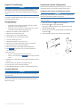
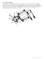
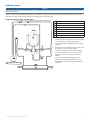
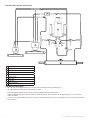
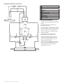
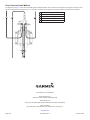
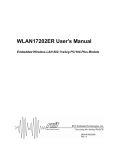
About the 2.1 L Hydraulic Pump
2.1 L Hydraulic Pump Installation
Instructions
To obtain the best performance and to avoid damage to your boat,
install the Garmin® 2.1 L hydraulic pump according to the following
instructions. These instructions are a supplement to the installation
instructions provided with your Garmin autopilot.
Professional installation of the pump is highly recommended, because
specific knowledge of hydraulic steering componentry is required to
properly install the pump.
Read all installation instructions before proceeding with the
installation. If you experience difficulty during the installation, contact
Garmin Product Support.
Registering Your Product
Help us better support you by completing your online registration today.
• Go to http://my.garmin.com.
• Keep the original sales receipt, or a photocopy, in a safe place.
Contacting Garmin Product Support
Contact Garmin Product Support if you have any questions about this
product.
• In the USA, go to www.garmin.com/support, or contact Garmin
USA by phone at (913) 397.8200 or (800) 800.1200.
• In the UK, contact Garmin (Europe) Ltd. by phone at 0808 2380000.
• In Europe, go to www.garmin.com/support and click Contact
Support for in-country support.
Important Safety Information
‹ warning
Your are responsible for the safe and prudent operation of your
vessel. The autopilot is a tool that will enhance your capability to
operate your boat. It does not relieve you from the responsiblility of
safely operating your boat. Avoid navigational hazards and never leave
the helm unattended.
See the Important Safety and Product Information guide in the autopilot
product box for product warnings and other important information.
‹ caution
Failure to install and maintain this equipment in accordance with these
instructions could result in damage or injury.
Always wear safety goggles, ear protection, and a dust mask when
drilling, cutting, or sanding.
notice
This equipment should be installed by a qualified marine installer.
This equipment is only for use with Garmin autopilots.
When drilling or cutting, always check the opposite side of the surface.
Be aware of fuel tanks, electrical cables, and hydraulic hoses.
The 2.1 L hydraulic pump steers your boat by interacting with the
hydraulic steering system, based on commands you enter using the
autopilot display unit. The pump is not included in the autopilot core
package box because the type of pump you use with your autopilot is
determined by the size and type of steering system on your boat.
Hardware Needed
• 2.1 L pump kit (part number 010-11099-10)
• Hydraulic hose with machine-crimpted or field-replaceable fittings
that have a minimum rating of 1000 lbf/in2.
• Inline hydraulic shut-off valves
• Hydraulic fluid
• Thread sealant
• Hydraulic bleeding equipment
• Mounting screws: mounting screws are provided in the pump kit, but
if the provided screws are not appropriate for the mounting surface,
you must provide the correct types of screws.
Tools Needed
•
•
•
•
•
•
•
•
Safety glasses
Drill and drill bits
Wrenches
Wire cutter/strippers
Screwdrivers: Phillips and flat-head
Cable ties
Marine sealant
Marine corrosion inhibitor spray
Pump Installation
Because every boat is different, care must be taken when planning the
pump installation.
1.
2.
3.
4.
Choose a mounting location (page 1).
Mount the pump (page 2).
Connect the pump to the hydraulic lines (page 2).
Connect the pump to the autopilot ECU (page 2).
Choosing a Mounting Location
1. Consult the diagrams on pages 5–7 for connection and dimension
considerations.
2. Choose a location to install the pump, considering the following
guidelines:
• The pump must be located within 19 in. (0.5 m) of the ECU.
• The cables that connect the pump to the ECU cannot be
extended.
• The pump should be mounted horizontally, if possible.
• If the pump cannot be mounted pump horizontally, it must be
mounted vertically with the pump head connectors facing up.
• The pump must be mounted in a location to which you can
extend the hydraulic steering lines of the boat.
• The pump has five hydraulic-connector fittings, enabling
an alternate installation method. Refer to page 4 to view an
illustration of the fitting layout and page 8 to view an illustration
of the alternate installation method.
2.1 L Hydraulic Pump Installation Instructions
1
Mounting the Pump
Before you mount the pump, if your boat has an unbalanced cylinder
steering system, you must re-configure the pump to work properly with
the unbalanced cylinder (page 3).
1. After you select a mounting location, determine the mounting
hardware needed for the surface.
Mounting hardware is included with the pump, but it may not be
suitable for the mounting surface.
2. If necessary, purchase the mounting hardware.
3. Hold the pump in the intended mounting location and mark the
locations of the mounting holes on the mounting surface, using the
pump as a template.
4. Using a drill bit appropriate for the mounting surface and selected
mounting hardware, drill the four holes through the mounting
surface.
5. Secure the pump to the mounting surface using the selected
mounting hardware.
Connecting the Pump to Hydraulic Lines
Notice
Do not attempt to use the autopilot to steer the boat until you bleed all
air from each part of the hydraulic system (page 3).
When adding hydraulic line to the system, use only hose with machinecrimped or field-replacable fittings that have a minimum rating of
1000 lbf/in2.
Do not use plumber’s tape on any hydraulic fitting. Use an appropriate
thread sealant rated for marine use on all pipe threads in the hydraulic
system.
Before you connect the pump to the hydraulic lines, refer to one of these
diagrams to find the correct place to add the pump and fittings to the
hydraulic system.
• Single helm without power assist (page 5)
• Dual helm without power assist (page 6)
• Single helm with power assist (page 7)
• Five-connector install method (page 8)
The diagrams on pages 5–7 show the recommended pump installation
method, with t-connectors in the hydraulic steering lines of the boat,
using only three fittings on the manifold. However, it is possible to
install the pump using the five-connector method shown on page 8.
Single Helm without Power Assist
1. Disconnect the necessary lines from the hydraulic system.
2. Add a t-connector to the starboard and port lines of the system.
3. Add hydraulic hose to the unused fitting on each t-connector,
sufficient to connect the t-connector to the pump fittings.
4. Connect the starboard line t-connector to the H1 or H2 pump fitting.
5. Connect the port line t-connector to the H pump fitting that you did
not use in step 4.
6. Install the Shadow Drive to the port or starboard hydraulic line
between the helm and the t-connector.
See the installation instructions provided with your Garmin autopilot
for Shadow Drive installation instructions.
7. Connect the return line from the helm to the Tank fitting of the
pump.
8. Install a shut-off valve (page 2) on each hydraulic line that connects
directly to the pump (optional).
9. Insert, tighten, and seal the included plugs in the unused pump
fittings.
Dual Helm without Power Assist
1. Disconnect the necessary lines from the hydraulic system.
2. Add a t-connector to the starboard and port lines of the system
between the helm t-connector and the steering cylinder.
3. Add hydraulic hose to the unused fitting on each t-connector,
sufficient to connect the t-connector to the pump fittings.
4. Connect the starboard line t-connector to the H1 or H2 pump fitting.
5. Connect the port line t-connector to the H pump fitting that you did
not use in step 4.
6. Install the Shadow Drive to the port or starboard hydraulic line
between the helm t-connector and the pump t-connector.
See the installation instructions provided with your Garmin autopilot
for Shadow Drive installation instructions.
7. Connect the return line from the helm t-connector to the Tank fitting
of the pump.
8. Install a shut-off valve (page 2) on each hydraulic line that connects
directly to the pump (optional).
9. Insert, tighten, and seal the included plugs in the unused pump
fittings.
Single Helm with Power Assist
1. Disconnect the necessary lines from the hydraulic system.
2. Add a t-connector to the starboard and port lines of the system
between the power assist module and the steering cylinder.
3. Add hydraulic hose to the unused fitting on each t-connector,
sufficient to connect the t-connector to the pump fittings.
4. Connect the starboard line t-connector to the H1 or H2 pump fitting.
5. Connect the port line t-connector to the H pump fitting that you did
not use in step 4.
6. Install the Shadow Drive to the port or starboard hydraulic line
between the helm and the t-connector.
See the installation instructions provided with your Garmin autopilot
for Shadow Drive installation instructions.
7. Add a t-connector to the return line between the power assist module
and the helm.
8. Connect the return line from the helm to the Tank fitting of the
pump.
9. Install a shut-off valve (page 2) on each hydraulic line that connects
directly to the pump (optional).
10.Insert, tighten, and seal the included plugs in the unused pump
fittings.
Shut-Off Valve
Garmin recommends the installation of shut-off valves on each
line connected to the pump. The shut-off valves allow you to easily
disconnect and remove the pump from the hydraulic system without
affecting helm steering. Refer to the diagrams on pages 5–7 to view
ideal shut-off valve placement.
Connecting the Pump to the ECU
Before you connect the pump to the ECU, you must mount the pump
(page 2) and ECU.
See the installation instructions provided with your Garmin autopilot for
ECU installation instructions.
Connect the two cables from the pump to the ports on ECU marked
DRIVE and FEEDBACK.
The ports are keyed to the appropriate fittings on the cables.
2
2.1 L Hydraulic Pump Installation Instructions
Hydraulic Fluid Bleeding
Unbalanced Cylinder Configuration
notice
The following is a general procedure for bleeding a hydraulic steering
system. Refer to the instructions provided by the manufacturer of
the steering system for more-specific information about bleeding the
system.
Configuring the Pump for an Unbalanced Cylinder
Before you bleed the hydraulic system, ensure that all hose connections
are complete and fully tightened. The pump has a bypass valve to allow
air to be bled from the system.
Hydraulic Bleeding
1. Complete an action:
• If the helm reservoir contains insufficient fluid, fill it with the
appropriate amount of hydraulic fluid.
• If the helm reservoir contains excess fluid, remove the excess to
avoid fluid overflow during the bleeding process.
2. Manually steer the helm to both cylinder stops.
3. Manually steer the helm fully to port.
4. Open a bypass valve at the cylinder fitting.
5. Turn the helm slowly to port for three minutes.
6. Close the cylinder bypass valve.
7. Add fluid to the helm reservoir if necessary.
8. Repeat steps 2 through 7 until the helm reservoir remains full.
9. Open the bypass valve on the pump manifold.
10.Turn on the autopilot system and disable the Shadow Drive.
11.Hold
on the GHC 10 for 10 seconds and watch for
steering movement.
12.Select an option:
• If there is steering movement, proceed to step 13.
• If there is no movement, hold
until steering movement
occurs.
13.Hold the soft key that produces steering movement and steer fully to
the stop.
14.Steer the helm to the opposite stop using the GHC 10.
15.Close the bypass valve on the pump manifold.
16.When hydraulic bleeding is complete, re-enable the Shadow Drive.
If the boat has an unbalanced cylinder steering system, you must
configure the pump to work properly with the steering system.
Notice
Keep all parts clean and free of dust and debris while configuring the
pump for an unbalanced-cylinder steering system.
If you remove the check valves after bleeding the hydraulic system, you
must bleed it again.
1. Remove the check valves ➊ from the pump manifold.
2. Pull the pistons ➋ out of the pump manifold.
The pump is configured from the factory with the pistons in the
balanced configuration ➌.
3. Re-insert the pistons into the pump manifold in the unbalanced
configuration ➍.
4. Insert and tighten the check valves into the pump manifold.
➊
➌
➋
➍
Corrosion Blocker
notice
To ensure long life of all parts, apply corrosion blocker to the pump at
least twice yearly.
After the pump installation is complete and all hydraulic connections
and electrical connections are made, apply a marine-rated corrosion
blocker to the pump.
2.1 L Hydraulic Pump Installation Instructions
3
Pump Valves and Fittings
The 2.1 L pump can be connected to the hydraulic system using one of two methods. The five-connector method (page 8) uses the C1 ➊ and
C2 ➋ fittings to connect the pump to the cylinder and the H1 ➌ and H2 ➍ fittings to connect the pump to the helm. The three-connector method
(pages 5–7) uses only the H1 and H2 fittings, with a t-connector splitting the connection between the helm and cylinder. The return line fitting ➎ is
used in both cases to connect to only the helm. The check valves ➏ do not need to be reconfigured if the boat is equipped with a balanced cylinder.
If the boat is equipped with an unbalanced cylinder, the check valves must be reconfigured (page 3). The bypass valve ➐ is only opened for
hydraulic bleeding, and must be fully tightened during normal operation.
➊
➌
➏
➎
➋
➐
➍
4
2.1 L Hydraulic Pump Installation Instructions
Hydraulic Layouts
notice
If the steering system in your boat does not match any of the hydraulic layouts in this manual and you are unsure how to install the pump, contact
Garmin Product Support.
Before you start the pump installation, identify the type of hydraulic steering system in your boat. Each boat is different, and you must consider
certain aspects of the existing hydraulic layout before deciding where to mount the pump.
Single-Helm without Power Assist Layout
➊
➋
➊
➋
➌
➌
➍
➎
➏
➐
➑
➍
➎
➏
➏
➐
➏
Shadow Drive
Port line
Return line
Pump
Starboard line
Shut-off valves
Helm
Steering cylinder
Installation Considerations
• The pump must be reconfigured if the boat is equipped
with an unbalanced steering cylinder (page 3).
• The pump should be mounted the pump horizontally
if possible.
• If the pump must be mounted vertically, mount it with
the hydraulic connections facing upward.
• Garmin recommends using the t-connector method
to connect the hydraulic lines to the pump. See the
diagram page 8 to view the alternate connection
method.
• To allow for easy pump disabling and removal,
Garmin recommends installing shut-off valves in
the hydraulic lines between the pump manifold and
t-connectors.
➑
2.1 L Hydraulic Pump Installation Instructions
5
Dual Helm without Power Assist Layout
➊
➋
➌
➍
➎
➏
➏
➐
➏
➑
➒
➊
➋
➌
➍
➎
➏
➐
➑
➒
Return line
Shadow Drive
Port line
Starboard line
Pump
Shut-off valves
Lower helm
Upper helm
Steering cylinder
Installation Considerations
• The pump must be reconfigured if the boat is equipped with an unbalanced steering cylinder (page 3).
• The pump should be mounted the pump horizontally if possible.
• If the pump must be mounted vertically, mount it with the hydraulic connections facing upward.
• Garmin recommends using the t-connector method to connect the hydraulic lines to the pump. See the diagram page 8 to view the alternate
connection method.
• To allow for easy pump disabling and removal, Garmin recommends installing shut-off valves in the hydraulic lines between the pump manifold
and t-connectors.
6
2.1 L Hydraulic Pump Installation Instructions
Single Helm with Power Assist Layout
➋
➊
➊
➋
➌
➌
➍
➍
➎
➏
➐
➎
➑
➒
➏
➐
➑
➑
➑
Shadow Drive
Port line
Starboard line
Return line
Helm
Power assist module
Pump
Shut-off valves
Steering cylinder
Installation Considerations
• The pump must be reconfigured if the boat is
equipped with an unbalanced steering cylinder
(page 3).
• The pump should be mounted the pump
horizontally if possible.
• If the pump must be mounted vertically, mount
it with the hydraulic connections facing upward.
• Removal of the power assist module may be
necessary to gain access to the fittings, hoses,
and bleed-tee fitting.
• The pump must be installed between the
cylinder and the power assist module.
• Garmin recommends using the t-connector
method to connect the hydraulic lines to the
pump. See the diagram page 8 to view the
alternate connection method.
• To allow for easy pump disabling and removal,
Garmin recommends installing shut-off valves
in the hydraulic lines between the pump
manifold and t-connectors.
➒
2.1 L Hydraulic Pump Installation Instructions
7
Five-Connector Install Method
The diagrams on pages 5–7 show the recommended pump installation method, with t-connectors in the hydraulic steering lines of the boat, using
only three fittings on the manifold. However, it is possible to install the pump using the five-connector method, as shown in this illustration.
➊ Port line to steering cylinder
➋ Return line to helm
➊
➋
➌
➌ Starboard line to steering cylinder
➍ Port line to helm
➎ Starboard line to helm
➍
➎
© 2011 Garmin Ltd. or its subsidiaries
Garmin International, Inc.
1200 East 151st Street, Olathe, Kansas 66062, USA
Garmin (Europe) Ltd.
Liberty House, Hounsdown Business Park, Southampton, Hampshire, SO40 9LR UK
Garmin Corporation
No. 68, Zhangshu 2nd Road, Xizhi Dist., New Taipei City, 221, Taiwan (R.O.C.)
www.garmin.com
March 2011
190-01333-02 Rev. A
Printed in Taiwan