1
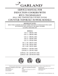
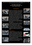
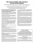
INSTALLATION & OPERATING
INSTRUCTIONS FOR
THE GARLAND 1/2-SIZE
ELECTRIC MOISTURE PLUS,
MODEL MPOE5L
FOR YOUR SAFETY
DO NOT STORE OR USE GASOLINE OR OTHER
FLAMMABLE VAPORS OR LIQUIDS IN THE
VICINITY OF THIS OR ANY OTHER APPLIANCE.
WARNING:
IMPROPER INSTALLATION, ADJUSTMENT,
ALTERATION, SERVICE OR MAINTENANCE CAN
CAUSE PROPERTY DAMAGE, INJURY OR DEATH.
READ THE INSTALLATION, OPERATION AND
MAINTENANCE INSTRUCTIONS THOROUGHLY
BEFORE INSTALLING OR SERVICING
THIS EQUIPMENT.
PLEASE READ ALL SECTIONS OF THIS MANUAL AND RETAIN FOR FUTURE REFERENCE.
THIS PRODUCT HAS BEEN CERTIFIED AS COMMERCIAL COOKING EQUIPMENT AND MUST BE INSTALLED
BY PROFESSIONAL PERSONNEL AS SPECIFIED.
Users are cautioned that maintenance and repairs must be performed by a Garland authorized service agent using genuine
Garland replacement parts. Garland will have no obligation with respect to any product that has been improperly installed,
adjusted, operated or not maintained in accordance with national and local codes or installation instructions provided
with the product, or any product that has its serial number defaced, obliterated or removed, or which has been modified
or repaired using unauthorized parts or by unauthorized service agents. For a list of authorized service agents, please refer
to the Garland web site at http://www.garland-group.com. The information contained herein, (including design and parts
specifications), may be superseded and is subject to change without notice.
Continuous product improvement is a Garland policy, therefore design and specifications are subject to change without notice.
GARLAND COMMERCIAL INDUSTRIES
185 East South Street
Freeland, Pennsylvania 18224
Phone: (570) 636-1000
Fax: (570) 636-3903
Part
Part##4518084
4518084Rev.
Rev.11(09/04)
(09/04)
GARLAND COMMERCIAL RANGES,
LTD.
1177 Kamato Road, Mississauga, Ontario L4W 1X4
CANADA
Phone: 905-624-0260
Fax: 905-624-5669
Enodis UK LTD.
Swallowfield Way, Hayes, Middlesex UB3 1DQ ENGLAND
Telephone: 081-561-0433
Fax: 081-848-0041
© 2004 Garland Commercial Industries,Page
Inc.1
Page 2
Part # 4518084 Rev. 1 (09/04)
TABLE OF CONTENTS
DIMENSIONS AND SPECIFICATIONS ........................................................................4
INSTALLATION ..............................................................................................................5
Electrical Connection ........................................................................................................5
WATER CONNECTION .................................................................................................5
OPERATING INSTRUCTIONS .....................................................................................6
Description of Controls......................................................................................................6
Display ..............................................................................................................................6
On/Off Button ..................................................................................................................6
Upper Right Blank ............................................................................................................6
Lower Right Blank ............................................................................................................6
Product Buttons (1 – 17) ..................................................................................................7
Number Buttons 1 – 0: .....................................................................................................7
Cancel Button ...................................................................................................................7
Preheat Buttons ................................................................................................................7
LED’s ................................................................................................................................7
Control Operation .............................................................................................................8
Startup and Normal Operation .........................................................................................8
During the Cooking Cycle: ...............................................................................................8
Shutdown (Auto Cool Down) ...........................................................................................8
Control Programming .......................................................................................................9
Recipe Programming.........................................................................................................9
System Programming ......................................................................................................10
Diagnostics Mode ...........................................................................................................11
Buttonpad Test ..........................................................................................................11
Door Switch Test ......................................................................................................11
Proper Door Switch Activation: .................................................................................11
Fan Speed Test ..........................................................................................................12
Heat Test...................................................................................................................12
Moisture Test ............................................................................................................12
Temperature Calibration ...........................................................................................12
Control Safety Features.................................................................................................... 13
Installing a New Recipe Program .................................................................................... 13
Using the CARD Reader ................................................................................................13
CLEANING AND MAINTENANCE ............................................................................ 14
Check Calibration ............................................................................................................ 14
Break in Period................................................................................................................14
Oven Cleaning ................................................................................................................. 14
Exterior ...........................................................................................................................14
Interior ............................................................................................................................15
Motor Care ...................................................................................................................... 15
Part # 4518084 Rev. 1 (09/04)
Page 3
DIMENSIONS AND SPECIFICATIONS
������
������
����������
�����������
��������������
���
�������
����
��������
Installation Notes:
����
���������
������
������
• Counter-mounted equipment
shall be designed to be sealed
to the counter, table, raised
base, or shelf.
• Each oven deck requires a
separate electrical connection.
���
�������
• Garland recommends a
separate 30 amp circuit be
provided for each oven.
�������
�������
����
��������
• Customer must provide a
1/4" NPT water connection
capable of 20 psig (minimum),
to 100 psig (maximum).•
Garland recommends the
following minimum water
conditions:
60 ppm coral dissolved solids,
20 ppm alkalinity, 13 ppm
silica, 30 ppm chloride, pH
factor greater than 7.5.
�������
�������
�����
�����
���
�������
����
��������
���
�������
����
���������
�����������
• Customer must provide a floor
drain or similar device.
• It is the responsibility of the
purchaser to install and
maintain the water supply to
the moisture+ oven.
Failure to provide satis�����������
factory water quality to
�����������
������������
operate the oven properly
�����������
can cause damage to integral components and void
the warranty.
�������
��������
���
�������
������
�������
�����
����
�
�������
�������
�
���������
��������������������������������������
Total kW
����������
Total kW Per Line
208/240
8.0
�
����������
208V 3 Ph
This oven must be
installed to comply with
applicable federal, state,
or local plumbing codes.
���
������� �������
�������
����� ���
Nominal Amperes Per Line
240V 3 Ph
208V 3 Ph
240V 3 Ph
X-Y
Y-Z
X-Z
X-Y
Y-Z
X-Z
L1
L2
L3
L1
L2
L3
2.6
2.6
2.6
2.6
2.6
2.6
22.2
22.2
22.2
19.3
19.3
19.3
Electrical specifications are per-oven, and include motor requirements.
Clearances
Entry
Installation
Shipping
Weight
Service
Crated
Uncrated
Sides
Rear
Right Side
Rear
36" (914mm)
31" (787mm)
1" (25mm)
1" (25mm)
20" (508mm)
20" (508mm)
Page 4
380lbs. (173kg)
Part # 4518084 Rev. 1 (09/04)
INSTALLATION
Proper placement of the oven will ensure operator
convenience and satisfactory performance. Adequate
clearance must be provided for cleaning, servicing,
and proper operation. (Refer to chart on page 4. for
minimum clearances.)
Electrical Connection
Before attempting the electrical connection, the rating
plate should be checked to confirm that the oven’s
electrical characteristics and the electrical supply are
compatible. The plate is located on the inside surface of
the control panel/body side.
• Attach the appropriate plug to the end of the cord
supplied with the oven.
• Visually inspect all electrical connections. A wiring
diagram is affixed to the inside surface of the control
panel/body side section.
Installation of the wiring must be made in accordance
with local codes, and the National Electrical Code,
ASNI/NFPA 70-1990, or in Canada, the Canadian
Electrical Code in regards to:
1. Switch panel size
2. Overload protection
3. Wire type
4. Wire size
5. Temperature limitations of wires
6. Method of connection, (conduit, cable, etc.)
WATER CONNECTION
It is the responsibility of the purchaser to install and
maintain the water supply to the moisture+ oven. Failure
to provide satisfactory water quality to operate the oven
properly can cause damage to integral components
and void your warranty. This oven must be installed
to comply with the applicable federal, state, or local
plumbing codes.
Water supply connection to the moisture+ is made via
a 1/4” NPTF fitting at the rear of the oven. The ability
to move the oven for service and cleaning may be a
consideration when choosing the type of connection
and supply line to be attached at this fitting.
The moisture+ water delivery system includes a water
pressure regulator that has been pre-set to operate at 10
psi. The water supply must maintain at least 20 psi and a
flow rate of three gallons per minute for proper operation
of the oven’s moisture injection system.
Water Quality
Garland recommends that the supply water be filtered
before it enters the oven’s water delivery system. This
will extend the life of the oven and its water delivery
system components by minimizing particles in typical
Part # 4518084 Rev. 1 (09/04)
tap water sources that cause scaling and buildup of
mineral deposits.
It is recommended that your supply water not exceed
any of the following parameters: 60 PPM total dissolved
solids; 20 ppm alkalinity; 13 ppm silica; 30 ppm chloride;
PH factor of 7.5.
Consult a local water treatment specialist for
recommendations regarding your water supply system
and its use with this oven. The use of highly mineralized,
(‘hard’), water could negatively affect the quality of
products prepared using the oven. The potability of
supply water does not guarantee its suitability for use
with the moisture+.
Drain
Your moisture+ oven has a gravity drain in the left rear
corner of the oven cavity. The drain pipe that exits the
rear of the oven must be directed downward toward the
floor, and should run directly to an open floor drain.
Avoid using flexible hose that could sag or kink, allowing
water to accumulate. The drain must be vented. This
connection must be at least 3/4" NPT, and configured
in accordance with local codes.
Page 5
OPERATING INSTRUCTIONS
Description of Controls
Display
The display shows information about the control and
its current operation mode i.e.: product name, time,
program mode, etc.
On/Off Button
The On/Off Button is used to toggle the oven on/off.
Upper Right Blank/Temp Button
This button has several functions:
1. Pressing the temp button will display the
actual and set temperatures of the oven.
The temperatures will be displayed for
three, (3) seconds.
2. Holding the temp button for three, (3)
seconds will toggle the control between °F and °C
or °C and °F. The control will beep three, (3), times
when the temperature units have changed.
3. In Programming, this Blank Button functions as
the YES button and is used to toggle values, i.e. fan
high/low.
4. In Diagnostics Mode, this Blank Button is used to
scroll through the different tests.
Lower Right Blank/Program Button
This button has two functions:
1. Press and hold the PROG button to enter
the programming features of the control.
Press and hold for three, (3), seconds.
Enter the required code:
4-2-7-5: To enter Recipe Programming
4-2-7-6: To enter System Programming
3-4-2-4: To enter Diagnostics Mode
2. While in programming, this Blank Button will
function as the Enter Button.
Page 6
Part # 4518084 Rev. 1 (09/04)
OPERATING INSTRUCTIONS continued...
Product Buttons (1 – 17)
*NOTE: Preheat Bread has additional functions:
The product buttons are used to select pre-programmed
recipes for each product. (Programming is available for
all product buttons.)
1. In Programming, Preheat Bread 425
scrolls through available values (i.e. high/
low fan speed) and is used as the NO
button.
Number Buttons 1 – 0:
The first ten Product Buttons,
outlined on the previous page, are
used to enter programming values,
i.e. code, set temperature, etc. They
correspond to the numbers 1 – 0 as
show to the right.
Cancel Button
The Cancel Button has several functions:
1. Press the Cancel Button to cancel the current menu
selection (if multiple cook cycles are in progress, the
last cycle started will be the first one canceled.)
2. In idle mode, press the Cancel Button to turn the
oven light on/off.
3. Press the Cancel Button to stop the alarm from
beeping and the display from flashing when a cook
cycle ends.
4. Press the Cancel Button to exit Recipe Programming,
System Programming, and Diagnostics Mode.
Preheat Buttons
Preheat Bakery 325, Preheat Bakery 350, and Preheat
Bread 425 are used to preheat the oven to the different
temperatures required for the various items:
·
Preheat Bakery 325: 325°F, high fan speed
·
Preheat Bakery 350: 350°F, high fan speed
·
Preheat Bread 425: 425°F, high fan speed
Part # 4518084 Rev. 1 (09/04)
2. In Diagnostics Mode, the Preheat Bread
425 button is used to scroll through the
list of tests.
LED’s
• When the desired Preheat Button is
pressed the corresponding LED will illuminate.
The LED’s of the menu items that match the chosen
preheat temperature will also light.
• While cooking, the LED of the selected item will
blink to show the user which item is being cooked.
If multiple cook cycles are started, the LED of the
product that will finish first will flash faster than
the LED’s of the other products. The LED’s of
other items with the same recipes other than time,
i.e. same temperature, fan speed, and moisture,
will also light to show the user which items can be
additionally cooked in the oven.
• When a product cooking times out, the
corresponding LED will flash rapidly to alert the
user of which item to remove. Opening and closing
the door will begin the counter of the next product
to be removed.
Page 7
OPERATING INSTRUCTIONS continued...
Control Operation
Startup and Normal Operation
• Pressing the On/Off button will power up the
control and the oven will begin heating to Preheat
The user can select Preheat Bakery 350 or Preheat
Bread 425 to heat the oven to the respective settings.
The display will show “Preheat Bakery 1”, “Preheat
Bakery 2”, or “Preheat Bread”.
• NOTE: No other buttons are active at this point.
• When the oven temperature is within the ready
band (+/-50°F), the oven will display “Heat Soak”
and begin a ten-minute countdown timer to stabilize
the oven (Provided the oven temperature was at or
below 100°F at startup).
• After the ten minute heat soak, the oven will display
“Select Bakery 1” (Preheat Bakery 325), “Select
Bakery 2” (Preheat Bakery 350), or “Select Bread”
(Preheat Bread 425).
• LED’s will light for items that can be selected for
cooking.
• Pressing a product button (provided the LED is
illuminated) once will begin the countdown cycle
for the programmed time.
• NOTE: Any item that can also be cooked will have
its LED illuminated
During the Cooking Cycle:
1. The display will show the product and the count
down time remaining.
2. The LED of the selected item will flash and the
oven light will turn on.
3. Up to three, (3), more product buttons can be
selected for cooking as long as their LED’s are lit.
The count down time of the product that will be
done first will be displayed and the corresponding
LED will flash rapidly. The LED’s of the other
products cooking will flash slowly.
Page 8
4. The external display will show the count down time
of the item to be done first, then will switch to the
next item to be done and so on.
• NOTE: To cancel a cook cycle, Press the Cancel
button. If more than one cook cycle is active, pressing
Cancel will end the last cycle started.
5. When the cooking time expires, the name of the
product that finished along with “DONE” will show
on the display. Also, the corresponding LED will
flash and the alarm will sound. Open and close the
door, or press Cancel to clear the prompt. (If more
than one cook cycle is active, the finished product’s
LED will flash faster than the other LED’s.)
Shutdown (Auto Cool Down)
• With the oven on, pressing the On/Off button will
initiate a shutdown of the oven.
• If the oven temperature is less than 150°F, “OFF”
will be displayed for 30 seconds and then the control
will go blank.
• If the oven temperature is more than 150°F, auto
cool down mode will begin. Open the door slightly,
only the fan will run at high speed to cool the oven.
“Auto Cool Down” will show on the display.
• If the door is open too much, “Close Door Slightly”
will be displayed. Close the door until “Auto Cool
Down” is displayed.
• If the door is not open enough, “Open Door
Slightly” will be displayed. Open the door until
“Auto Cool Down” is displayed.
• Once the oven temperature falls below 150°F, the
fan will stop and the oven will display “OFF” for
30 seconds and then turn blank.
Part # 4518084 Rev. 1 (09/04)
OPERATING INSTRUCTIONS continued...
Control Programming
Recipe Programming
• NOTE: In programming product buttons (1-17),
each button can have different steps called Profiles. Each
profile can change the fan speed, cook temperature, cook
time, alarm, time mode, and moisture for a product.
If more than one profile is programmed for a product,
the product cannot be combined with other products.
• In order to start additional cook cycles; the recipes of the
products must be exactly the same except for cook time.
1. To program recipes for the product buttons (1-17),
press and hold the Program button for three, (3)
seconds. When prompted, enter the code: 4-2-75 using buttons 1 – 0. Press the “ENTER” (lower
right blank) button.
2. The display will prompt for a programmable button,
1-17. Press the desired button. The LED for the
selected button will light. Press “ENTER” (lower
right blank).
3. The display will show the message “Profile 1” in the
lower left corner and prompt for the Fan Speed on
the top line. Use the “YES” (upper right blank) and
“NO” (Preheat Bread 425) buttons to toggle fan
high and low. After selecting a fan speed, press the
“ENTER” (lower right blank).
4. The display will then prompt for the Cook
Temperature. Enter the temperature using buttons
1 – 0 and press the “ENTER” (lower right blank)
button.
Part # 4518084 Rev. 1 (09/04)
5. Next, the display will prompt for the Cook Time.
Enter the cooking time using buttons 1 – 0 and
press the “ENTER” (lower right blank) button.
6. Next, the display will ask for Alarm Time (to rotate
items). Enter the time using buttons 1 – 0 and press
“ENTER” (lower right blank). (Enter the time at
which the rotation needs to be done NOT how
long into the cook it needs to be done, i.e. 2:00
cook time, alarm time 1:30. Alarm will sound when
timer reaches 1:30 on the display (not 0:30).)
7. The display will ask for the Time Mode. Use “YES”
(upper right blank) and “NO” (Preheat Bread 425)
to toggle time mode between flex and straight time.
Press the “ENTER” (lower right blank) button.
8. The display will ask if Moisture is desired. Press the
“YES” (upper right blank) and “NO” (Preheat Bread
425) buttons to set moisture from NONE-LEVEL
9. Press the “ENTER” (lower right blank).
Moisture Level
Duration
NONE
0 PULSES
LEVEL 1
1 PULSE EVERY 5 SECONDS
LEVEL 2
1 PULSE EVERY 10 SECONDS
LEVEL 3
1 PULSE EVERY 15 SECONDS
LEVEL 4
1 PULSE EVERY 20 SECONDS
LEVEL 5
1 PULSE EVERY 25 SECONDS
LEVEL 6
1 PULSE EVERY 30 SECONDS
LEVEL 7
1 PULSE EVERY 35 SECONDS
LEVEL 8
1 PULSE EVERY 40 SECONDS
LEVEL 9
1 PULSE EVERY 45 SECONDS
Page 9
OPERATING INSTRUCTIONS continued...
9. The display will then ask if you would like to
continue programming for this product. Press
the “YES” (upper right blank) button to program
additional profiles (profile 2-6). Press the “NO”
(Preheat Bread 425) button to exit programming
for this product.
• NOTE: If programming additional profiles, repeat
steps 3-9 for each profile (Prof2 - Prof6).
10. The Display will ask for the Product Name
(selectable from a library of 40 names). Press the
“YES” (upper right blank) and “NO” (Preheat
Bread 425) buttons to scroll through the available
names and press “ENTER” (lower right blank) to
accept the desired name. The product LED will go
out.
3. Next, the Software Number will be displayed.
Press “ENTER” (lower right blank) to continue.
4. Next, the control Download Number will be
displayed. Press “ENTER” (lower right blank) to
continue.
5. The display will now show the SCK Address. Use
the buttons 1 – 0 to enter the desired address.
When finished, press “ENTER” (lower right blank)
to continue.
• NOTE: Upon pressing “ENTER” (lower right
blank) to accept the product name, you will return to
recipe programming
6. The display will now show Ignition Test. This
is primarily used in manufacturing only. Press
“ENTER” (lower right blank) to continue.
System Programming
• NOTE: System Programming can only be entered
when the control is in the idle or off state (System
Programming cannot be entered when the timer is
counting down)
7. Lastly, the control will perform a Display Test. The
entire display and all of the control LED’s will flash.
If any part of the display or any of the LED’s do
not light, there is a problem with the control board.
Press “ENTER” (lower right blank) to continue.
1. To enter System Programming, press and hold the
Program (lower-right blank) button for three, (3),
seconds. When prompted, enter the code: 4-2-76 using the buttons 1 – 0. Press “ENTER” (lower
right blank).
8. You will now return to the control Flash Number.
Press “CANCEL” to exit System Programming.
2. After entering the code and pressing “ENTER,”
the control Flash Number will be displayed. Press
“ENTER” (lower right blank) to continue.
Page 10
Part # 4518084 Rev. 1 (09/04)
OPERATING INSTRUCTIONS continued...
Diagnostics Mode
• To enter Diagnostics Mode, press and hold the
Program (lower right blank) button for three, (3),
seconds. When prompted, enter the code: 3-4-24 using the buttons 1 – 0. Press “ENTER” (lower
right blank).
• After entering the code and pressing “ENTER,” the
Moisture Plus Part Number will be displayed briefly
and then the display will change to Diagnostics
Test – Buttonpad Test. Use the “YES” (upper right
blank) and “NO” (Preheat Bread 425) buttons to
scroll through the available diagnostic tests. Press
“ENTER” to begin the desired test.
light, a buttonpad problem exists. After completing
the Buttonpad Test, you will return to Diagnostics
Mode. (Press “CANCEL” at any time during the
test to return to Diagnostics Mode.)
Door Switch Test
1. After selecting Door Switch Test and pressing the
“ENTER” (lower right blank) button, the display
will show the position of each of the two switches.
Open and close the door slowly to verify the
operation of the door switches.
Proper Door Switch Activation:
Buttonpad Test
1. The display will show “Press the On/Off Button”.
Upon pressing the On/Off button, the LED for the
ON/OFF button will light briefly and then go out
to show that the button works.
• Starting with the door closed, the switches
should read:
• Slowly begin to open the door. Door switch 1
should be the first to change states:
• Next, door switch 2 should change state to:
2. The display will then prompt the user to press
the “TEMP” button (upper right blank). After
the user presses the “TEMP” (upper right blank)
button, the corresponding LED will light to show
the button works. The control will then continue
to prompt the user to press the remaining control
buttons. If the LED of the button pressed does not
Part # 4518084 Rev. 1 (09/04)
• If the switches do not operate as stated above,
there is a problem with the door switches.
• Press “CANCEL” to exit the Door Switch Test
and return to Diagnostic Mode.
Page 11
OPERATING INSTRUCTIONS continued...
Fan Speed Test
1. After selecting Fan Speed Test and pressing
“ENTER” (lower right blank), the control will turn
the oven fan on LOW speed for ten seconds. Verify
that the fan is indeed running on low speed. The
control will show:
2. After a short while, the control will turn the fan on
HIGH speed for ten seconds. Verify that the fan is
indeed on high.
3. After a few seconds, the test will complete. Press
“CANCEL” to return to Diagnostics Mode.
Heat Test
1. After selecting Heat Test and pressing “ENTER”
(lower right blank), the control will show the actual
temperature of the oven and will turn the heaters
on. Verify that the actual temperature increases
during the test.
2. After a short while, the test will complete. Press
“CANCEL” to return to Diagnostics Mode.
Page 12
Moisture Test
1. After selecting Moisture Test and pressing
“ENTER”, the control will show the moisture
status as OFF for ten seconds.
2. The control will then turn moisture on for ten
seconds, verify that the moisture has actually
turned on within the oven by looking through the
glass door.
3. After a few seconds, the Moisture Test will complete.
Press “CANCEL” to return to Diagnostics Mode.
Temperature Calibration
1. After selecting Temperature Calibration and
pressing “ENTER”, the display will show the
Actual Temperature inside the oven. Verify the
cavity temperature using a pyrometer.
• NOTE: If the oven temperature is below 200°F,
Temperature Calibration will not be active and the
display will show Low Temp.
2. Press and hold the “TEMP” (upper right blank)
button for three, (3), seconds. The display will
show the Actual Temperature on the first line and
Set Temperature on the second line. If the Actual
Part # 4518084 Rev. 1 (09/04)
OPERATING INSTRUCTIONS continued...
Temperature does not correspond to the pyrometer,
enter the value on the pyrometer using buttons 1
– 0. The value will be input as Set Temp.
3. Press “ENTER” (lower right blank) to accept the
changes. The Actual Temperature will change to
equal the value input for Set Temperature. Press
Cancel to exit Temperature Calibration.
• After the desired Tests are complete, press
“CANCEL” to exit Diagnostics Mode.
Control Safety Features
The control has several built in safety features to protect
both the user and the oven itself.
• If the actual temperature inside the oven exceeds
the set temperature by 50°F, the display will show
“HI TEMP” and the alarm will sound. The fan will
continue to run, however, power to the heaters will
be cut.
• In the event of a temperature probe failure, the
control will become inoperative and the display
will show “PROBE ERROR”. Once the problem
is corrected, the control must be cycled On/Off
(using the ON/OFF button) in order to become
operative again.
Installing a New Pecipe Program
Using the CARD Reader
1. Remove the two screws securing the controller
button pad to the front panel using a Phillips head
screw driver, and drop the button pad to access the
CARD reader.
2. Press and hold the programming
button (bottom right button), until the
controller display reads “enter code”.
3. Insert the CARD into the reader with
gold side up.
4. The LED on the reader will illuminate
yellow for five seconds then red during the coding.
• If the actual temperature sensed inside the oven
exceeds 575°F, the control will change to “HELP”
and the alarm will sound continuously. All control
operations will shut down except the alarm.
5. When the LED changes color to green, remove the
card.
6. Program is complete. Close the panel and exit the
program mode by hitting the cancel button.
7. Power down the oven and re-start.
• NOTE: The control will need a complete power
down and restart (unplug/plug in oven) before
any control functions will become operational. If
the problem persists, contact a service technician.
Part # 4518084 Rev. 1 (09/04)
Page 13
CLEANING AND MAINTENANCE
Check Calibration
Tools: Digital thermometer with probe; oven mitt.
See also, Temperature Calibration on page 12.
1. Clamp the probe in the center of the middle rack.
2. Pass the probe wire out of the oven between the
door and the door seal and close the door.
3. Plug the probe wire into the thermometer.
4. Press the oven On/Off button.
5. Press the “Preheat Bakery 350” button to heat
the oven to 350°F. Allow the oven to preheat for
approximately 30 minutes before calibrating.
Break in Period
When the oven is new, heat the oven to “Preheat
Bread 425), and leave the oven idle for one hour before
beginning normal operation.
Oven Cleaning
Exterior
• NOTE: Disconnect the oven from the power supply
before cleaning or servicing.
• Establish a regular cleaning schedule. Any spills
should be wiped off immediately.
Tools: Mild detergent; hot and warm water; sponge
or soft cloth; clean, dry cloth; possible non-metallic
scour pad; possible scouring powder.
Page 14
1. The oven should be allowed to cool sufficiently
before beginning the cleaning procedure.
2. Wipe exposed cleanable surfaces when cool with
a mild detergent and hot water. Stubborn residue
spots may be removed with a lightweight nonmetallic scouring pad. Dry thoroughly with a clean
cloth.
3. Painted surfaces should be cleaned using a mild
soap and warm water solution on a sponge or soft
cloth. Dry thoroughly.
4. Stainless Steel surfaces may also be cleaned using a
mild soap and warm water solution on a sponge or
soft cloth. Stubborn stains may be removed using a
non-metallic abrasive pad, rubbing in the direction
of the metal’s grain. If necessary, for particularly
heavy spots, you may mix a thin paste of water and
scouring powder, and apply it with a sponge. Be
careful to apply light pressure and remember to rub
only in the direction of the metal’s grain.
5. The control panel surface is easily cleaned with
hot water, soap, and a soft cloth. Do not use
hard abrasives, solvent type materials, or metallic
scouring pads since these will scratch and cloud the
surface.
6. Never spray the perforated areas or control panel
with steam or water as this will allow moisture
to enter the control cavity, which could damage
electrical components.
Part # 4518084 Rev. 1 (09/04)
CLEANING AND MAINTENANCE
Oven Cleaning
Motor Care
Interior
• The motor in this convection oven is maintenance
free since it is constructed with self-lubricating
sealed ball bearings. It is designed to provide durable
service when treated with ordinary care. There are a
few suggestions to follow on the care of the motor:
• NOTE: Disconnect the oven from the power supply
before cleaning or servicing.
• Establish a regular cleaning schedule. Any spills
should be wiped off immediately.
Tools: Supplied spray hose; brush; cloth
• NOTE: The spray hose connection is located behind
the front control panel. When cleaning the oven
interior, attach the supplied hose to the water connector
behind the control panel.
1. The oven should be allowed to cool sufficiently
before beginning the cleaning procedure.
2. Remove the racks, rack guides, and the baffle. Wipe
each with a clean, damp cloth.
3. Using the supplied spray hose, spray the inside of
the oven lightly to remove any deposits.
4. Wipe the interior with a clean damp cloth to remove
any remaining deposits and spots.
5. Brush the wheel as needed to remove any grease
and/or particles.
6. Carefully wipe the blower wheel and temperature
probe with a clean damp cloth.
• When the motor is operating, it cools itself
internally by air entering at the rear of the motor
case, provided proper clearance has been allowed.
• Since the blower wheel is in the oven cavity, it is
at the same temperature as the oven. If the motor
is stopped while the oven is hot, the heat from the
blower wheel is conducted down the shaft and
into the armature of the motor. This action could
shorten the life of the motor.
• It is recommended that at the end of a bake or
roasting period, when the oven will be idle for any
period of time or before shutting down completely,
the door be left open slightly and the “ON/OFF”
button pressed to put the oven into Auto Cool
Down. Once the internal temperature of the oven
falls below 150°F (66°C), the fan will stop running
and the display will show “OFF”. This feature
protects the oven motor from pre-mature failure.
Optimal cool down will be achieved with the door
open slightly.
7. Replace the baffle, rack guides, and racks. Return
the spray hose to its storage compartment.
Part # 4518084 Rev. 1 (09/04)
Page 15