1
Owner’s Manual
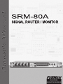
SRM-80A / E – SIGNAL ROUTER/MONITOR
SRM-80A
SIGNAL ROUTER / MONITOR
ROUTER /
MONITOR SERIES
SRM-80A / E – SIGNAL ROUTER/MONITOR
INTRODUCTION
ABOUT THE SRM-80
Congratulations on your purchase
of a Furman Model SRM-80A Signal
Router/Monitor. Your SRM-80A will
make monitoring, mixdown, and dubbing simpler and faster, thus helping
you achieve professional results.
SYSTEM
SETUP 1
MO N ITOR LIN E OUTPU T A
PO W ERE D SPEAKERS
IN PU T
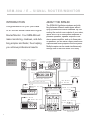
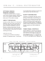
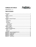
The SRM-80A facilitates mixdown and dubbing between different media types without
tying up additional console channels. By connecting the control room outputs of your mixer,
inputs and of up to three power amplifiers or
powered speakers, speaker outputs of one
stereo power amplifier, and up to three pairs
of speakers, you will have a highly useful and
sophisticated audio playback monitor system.
Multiple copies can be made simultaneously
through use of the SRM-80A’s four rotary
SPEAKER C OUTPU T
PA SSIVE SPEAKERS
SPEAKER B OUTPU T
PA SSIVE SPEAKERS
PO W ER AM PLIFIER
OU TPU T
H EAD PH O N ES
MO N ITOR LIN E OUTPU T B
MO N ITOR LIN E OUTPU T A
TO “A” N
I
FROM “A” OUT
OU TPU T
IN PU T
FROM
AM P(B)
OU TPU T
SRM -80A
TO SOURCE IN
D AT RECOR D ER
TO “B” N
I
FROM “B” OUT
OU TPU T
SET SW ITC H
TO SPK-B/C
FROM “C ” OUT
TO “C ” N
I
OU TPU T
MIN ID ISC
FROM “D ” OUT
TO “D ” N
I
IN PU T
OU TPU T
C ASSE TTE RECOR D ER
1
IN PU T
SRM -RU
SOURCE MIXER
IN PU T
COM PA C T D ISC PLAYER
-RECOR D ER -
SRM-80A / E – SIGNAL ROUTER/MONITOR
STEP-BY-STEP GUIDE TO SET-UP USING SINGLE POWER AMP
●
Please also refer to the “System Set-Up #1” drawing on the facing page.
●
Cables needed:
2 Pair:
1 Pair:
6 Pair:
2 Pair:
1 Pair:
1 Pair:
1 Pair:
Speaker to Binding Posts, the banana plug type (Speakers B, C)
1/4” TRS Balanced to Monitor Line output “A” (Powered Speakers)
RCA I/O to Devices
1/4” TRS Balanced to Device “A” L/R I/O
1/4” TRS Balanced to “SOURCE” L/R Input
1/4” TRS Balanced to Power Amp L/R Inputs
Power Amp Out to “FROM POWER AMP OUT” Binding Posts (banana plugs)
●
Make sure SRM-80 and all other devices are switched “OFF” before making any cable connections.
●
Decide which devices will be labeled “A”, “B”, “C”, and “D”. Device “A” should be any pro level balanced units,
such as a DAT machine. Label the Output Select Switch and the speaker pairs on the front panel tabs. Use
adhesive labels so you can relabel for different configurations.
●
Mount the SRM-80 in your rack. Depending on your setup, it may be easier to cable all your gear before mounting the SRM-80 in your rack. Otherwise, go ahead and mount it now.
●
Set AMP/SPK - B/C Switch to SPK - B/C.
●
Connect passive speaker cables to “SPEAKER C” and “SPEAKER B” Binding Posts.
●
Connect Power Amp L/R Output cables to “FROM AMP OUTPUT” Binding Posts.
●
If you have the optional SRM-RU remote unit, which we highly recommend, connect its 5-Pin
cable to “REMOTE.”
●
Connect 1/4” TRS Balanced cables from your powered monitors to MONITOR LINE OUTPUT “A” L/R.
●
Connect 1/4” TRS Balanced cables from MONITOR LINE OUTPUT “B” L/R to your power amp “IN” L/R.
●
Connect RCA cables from “L/R In/Out” to devices “B”, “C”, and “D”, according to your setup plan.
●
Connect 1/4” TRS Balanced cables from “A” L/R, I/O to device “A”
●
Connect 1/4” TRS Balanced cables from “SOURCE” L/R to source device.
(e.g. mixing console stereo out or soundcard out).
●
Set the Ground Lift Switch to the position that reduces any hum or buzz.
●
Set the “0db / +4db” switch to the appropriate meter scale for the equipment being used.
●
Power up your equipment, being sure to turn on your power amp
●
Set “SPEAKER TRIM” controls at about 75%. After powering up the system, adjust levels as needed. To dial in
your speaker levels use broadband pink noise and sound level meter. The Alan Parsons/Stephen Court alignment CD is very good, and a decent meter can be had for about $40 at Radio Shack.
last.
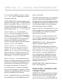
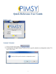
For using more than 1 pair of power speakers or multiple power amps see System Set-up #2 on the next page.
2
SRM-80A / E – SIGNAL ROUTER/MONITOR
source select knobs labeled OUTPUT SELECT A through OUTPUT SELECT D.
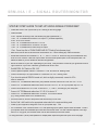
Monitoring any of these sources can be done
using the MONITOR SELECT knob, highpower headphone amp and uniquely thoughtout speaker selection system that consists of
three balanced line level speaker outputs A,
B, and C. All of these outputs are compatible
with powered monitors or passive speakers
using a power amp. The unique feature is that
the B and C outputs can be combined into one
output for use with 2 pairs of passive speakers
and only one power amp. See description of
SYSTEM
SETUP 2
MO N ITOR LIN E OUTPU T A
PO W ERE D SPEAKERS
B/C AMP/SPK Switch. Each monitor speaker
output has its own front panel trim control, so
equal listening levels can be maintained despite differences in speaker efficiencies.
The SRM-80A has balanced inputs for the
SOURCE and A inputs, and balanced outputs
for channel A output and A, B, and C monitor line outputs. INPUTS B through D utilize
unbalanced RCA jacks. The SRM-80A allows
easy signal routing between these dissimilar
jacks.
PASSIVE SPEAKERS
MO N ITOR LIN E OUTPU T B
PO W ERE D SPEAKERS
PO W ER AM PLIFIER
MO N ITOR LIN E
OU TPU T B
MO N ITOR LIN E OUTPU T A
OU TPU T
INP U T
H EAD PH O N ES
MO N ITOR LIN E
OU TPU T C
TO “A” N
I
FROM “A” OUT
OU TPU T
INP U T
SET SW ITC H
TO AM P-B/C
SRM -80A
TO SOURCE IN
D AT RECOR D ER
I
TO "B" N
FROM “B” OUT
OU TPU T
FROM “C ” OUT
TO “C ” N
I
OU TPU T
MIN ID ISC
FROM “D ” OUT
TO “D ” N
I
INP U T
OU TPU T
C ASSE TTE RECOR D ER
3
INP U T
SRM -RU
SOURCE MIXER
INP U T
COM PAC T D ISC PLAYER
-RECOR D ER -
SRM-80A / E – SIGNAL ROUTER/MONITOR
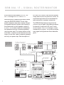
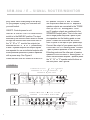
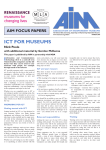
The SRM-80A provides a high-resolution 40
LED x 2 bar graph meter to display the signal
selected for listening. The meter displays a
pre-fader signal for accurate monitoring of
the signal going to tape or disc. This meter
has true VU ballistics, or can be switched to
Peak Program Mode via the front panel toggle
switch. The meter also features a slow release-time Peak Hold function to allow easy
verification of critical levels.
The SRM-80A’s MONO SUM feature provides
the ability to check for radio compatibility,
and is a good spot check to see how you’ve
Balanced Buffers
Source
1/4" TRS
Input A
1/4" TRS
Unbalanced Buffers
Input B
RCA
Input C
RCA
Input D
RCA
0 VU = 0dBu
0 VU = +4dBu
The SRM-80A also features a DIM switch to
allow an easy way to lower the level to the
speakers (but not the headphones) temporarily without disturbing any level controls.
Input to Output Routing Switches
Connect any Input to any Output --EXCEPT-- A cannot send to A, B cannot send to B etc.
B
C
D
S
Floating Bal. output Stage, 0dB gain
Routing
Select
4 position
(4 switches)
A
B
C
C
RCA
Monitor
Select
5 position
S
D
RCA
D
VU / PPM
Meter
Outputs
A
1/4" TRS
B
RCA
+6dB gain
Volume Control
and Mono Sum
Mono Control
Remote Control
messed up the stereo image! (Only the sends
to the speakers are affected.) While radio airplay is nearly always stereo these days, phasing problems and odd panning arrangements
can show up in less than ideal listening environments, such as cars, and many locations in
nightclubs.
Push button switches
(Amplifier Select, Mono, Dim)
5 Pin DIN
Amplifier Level Trim Pots
+6 dB gain
Speaker
Amplifier VCA
and floating
balanced
output stage
Headphone Volume
and Amplifier
+6dB gain
Amplifier Select Relays
Gain Control for Amp
A vs B vs C and DIM
Amp A
1/4" TRS
Amp B
1/4" TRS
Select Amp A vs Amp B/C
Select Amp / Spkr B/C
Amp B/C
or
Speaker B/C
Headphone
(Front Panel,
1/4" TRS)
Amp C
1/4" TRS
Low level Relay
Amp B Output
5 way post
To Speaker B
5 way post
High level Relay
To Speaker C
5 way post
4
SRM-80A / E – SIGNAL ROUTER/MONITOR
OPTIONAL SRM-RU
REMOTE CONTROL
ring the panel when tightening the screws, use
nylon washers under the screw heads.
The optional five-button SRM-RU allows remote control of Speaker Selection, MONO and
DIM. An LED indicator is provided for each
button and a 10 foot cable is included.
SAFETY INFORMATION
WARNING (For domestic units only): Do not
remove the third prong on the SRM-80A’s AC
plug. Never use a 3-prong to 2-prong AC plug
adapter to plug your SRM-80A into your wall
socket. The unit requires that a safety ground
be present for proper operation. Any attempt to
operate it without a safety ground is considered
improper operation and could invalidate the
warranty.
ABOUT THIS MANUAL
We want to make it easy for you to set up your
SRM-80A. Page Two of this manual tells you
how to do just that, step-by-step. Page four
gives you detailed information on all of the
features, controls and connectors. You can
set up your SRM-80A first, and read about the
controls afterwards or even better, just resume
recording and mixing!
FRONT PANEL CONTROLS
OUTPUT SELECT A: Use this input/output for
balanced, pro level devices. This four-position
knob determines which signal is routed to the
device plugged into the 1/4” “A” OUTPUTS on
the SRM-80A’s rear panel. For example, if the
“A” OUTPUTS are used for a DAT machine, the
INSTALLATION
The SRM-80A is intended for mounting in
standard 19" equipment racks. To avoid mar-
SW ITC H SETTIN
ING S FO R M U LTI
IC A SSE TTE D U BBING
C ASSE TTE
REC O RD ER
INPUT -D
INPUT -D
INPUT -D
C D PLAYER
INPUT -C
INPUT -C
INPUT -C
INPUT - B
INPUT - B
INPUT - B
INPUT -A
INPUT -A
INPUT -A
OUTPUT
SELEC T
A
OUTPUT
SELEC T
B
SET OUTPUT SELEC T SW ITC H ES
B AN D C TO IN
PUT -D .TH IS W ILL
ROUT TH E C D PLAYER TO BOT H
C ASSE TTE D EC KS C O NN EC TED TO
TH E B AN D C OUTPUT S
5
C ASSE TTE
REC O RD ER
OUTPUT
SELEC T
C
OUTPUT
SELEC T
D
D
C
B
A
SOU RCE
M O NITO R
SELEC T
SET M O NITO R SELEC T SW ITC H
TO D TO LISTEN TO WH AT S
I
BEIN
ING REC O RD ED TH ROU GH TH E
SPEAKERS AN D H EAD PH O N ES
SRM-80A / E – SIGNAL ROUTER/MONITOR
DAT can receive signals from device “Source”,
“B”, “C”, or “D” INPUTS depending on where
you position this knob.
OUTPUT SELECT B: This four-position knob
works like the output select “A” knob described
above. For example, if the “B” RCA OUTPUTS
on the back panel are used for a cassette
recorder, the recorder can receive signals from
stereo device Source, “A”, “C”, or “D” INPUTS.
OUTPUT SELECT C: The SRM-80A’s “C”
OUTPUTS can receive signals from device
“Source”, “A”, “B”, or “D” INPUTS depending
on where you position this knob. For example,
if the “C” RCA OUTPUTS on the back panel
are used for a MiniDisc recorder, the recorder can receive signals from stereo device
“Source”, “A”, “B”, or “D” INPUTS.
OUTPUT SELECT D: The SRM-80A’s “D”
OUTPUTS can receive signals from device
“Source” “A”, “B”, or “C” INPUTS. For example, if the “D” RCA OUTPUTS on the back
panel are used for a CD player/recorder, the
recorder can receive signals from stereo device “Source”, “A”, “B”, or “C” INPUTS.
MONITOR SELECT: This five-position knob
allows you to select which device you will hear
through your speakers and headphones, the
main console or soundcard mix (Source), or
the output of any devices “A” through “D”.
LISTENING LEVEL: Controls the loudness
level you hear through your speakers. It does
not affect the signal going to any of the stereo
devices connected to the SRM-80A.
MONO: Changes the sound you hear through
your speakers (not in the Headphones) from
stereo to monaural.
DIM: Attenuates the loudness of your speakers
by about 15 dB, without affecting the level of
the signals going to any of the stereo devices or
headphones connected to the SRM-80A. This
is a very useful feature if you are interrupted
while monitoring, mixing, or dubbing.
MONITOR LEVEL: This high-resolution, 40 x 2
LED bar graph meter allows precise pre-fade
level calibration for all stereo devices connected to the SRM-80A.
METER MODE: Located to the right of Monitor Level Meter, this switch can be set for the
meter to display AVG (VU) or Peak Mode.
SPEAKERS A, B, and C: Selects between
amplifier / speaker outputs A, B, or C.
TRIM LEVELS: Adjusting these “Set Once”
controls allows you to set all three pairs of amplifiers/speakers to the same listening level.
HEADPHONES: Plug your headphones in
here. The high-power headphone amp provides excellent audio quality and can drive
low-impedance phones with ease. It may be
wise to disconnect your headphones to avoid
damage when not in use.
HEADPHONE LEVEL: Adjusts the listening
level of the headphones.
REAR PANEL CONTROLS AND
CONNECTIONS
GROUND LIFT: Allows separation of chassis
ground from audio ground and can be used
to reduce hum or buzz. Remember, never
remove the third prong on the SRM-80A’s AC
6
SRM-80A / E – SIGNAL ROUTER/MONITOR
plug. Never use a three-prong to two-prong
AC plug adapter to plug your SRM-80A into
your wall socket.
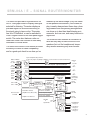
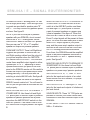
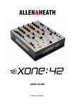
B/C position: Only the “A” and “B” monitor
line outputs are used and the “B” amplifier’s
speaker outputs are connected to the “FROM
AMP (B) OUTPUT” binding posts. The B
and C speaker outputs are combined to the
SPEAKER B output jacks. This is to be used
with a single power amp and 2 pairs of passive speakers via the binding posts on rear
panel. Connect the SPEAKER B/POWER
AMP IN jacks to the input of your power amp.
Connect the output of your power amp to the
FROM AMP OUTPUT Binding posts. Connect
1 pair of passive speakers to the SPEAKER
B binding posts and the other pair of passive
speakers to the SPEAKER C binding posts. To
select the associated amplifier / speaker press
the “A”, “B,” or “C” speaker select buttons on
the front panel. See Figure B.
ON/OFF: Controls power to unit.
AMP-B/C & SPK-B/C SWITCH: When the B/C
switch is in the AMP-B/C position: The input
selected by the Monitor Select switch is routed
through the Monitor level control and sent to
the “A”, “B” or “C” monitor line outputs (as
selected with the “A”, “B” or “C” pushbuttons).
B and C speaker outputs and output signals
are separate for use as individual outputs with
either powered speakers or passive speakers
with a power amp. See Figure A.
When the AMP/SPK B/C switch is in the SPKFIGURE A
AMP-B/C
C O NN EC TI
IO N S FO R 3 API
P IR S O F PO W ER ED
SPEA K ER S O R PA SS IV E SPEA K ER S WITH
SEPA R A TE PO W ER A MP S
AMP-B/C SPKB/C SWITCH IS
SET TO AMP-B/C
120 VAC INPUT 60 HZ
GROUND
ON
SPEAKER C
MADE IN CHINA
L
5 WATTS
SPK-B/C
SPEAKER B
R
AVIS:N'OUVREZ
L
R
L
USE MODEL
SRM-RU
ONLY
R
L
C
AMP-B/C SPKB/C SWITCH IS
SET TO SPK-B/C
120 VAC INPUT 60 HZ
GROUND
ON
CAUTION:
REFER SERVICING TO QUALIFIED PERSON
TO PREVENT ELECTRIC SHOCK DO NOT REMOVE COVER.
SPEAKER C
MADE IN CHINA
L
SPEAKER B
FROM AMP(B)
OUTPUT
R
L
R
L
REMOTE
USE MODEL
SRM-RU
ONLY
R
PAS-RISQUE DE CHOC ELECTRIQUE
L
C
CAUTION:
CONNECT
PASSIVE
SPEAKERS TO
SPEAKER C
OUTPUTS
TO PREVENT ELECTRIC SHOCK DO NOT REMOVE COVER.
CONNECT
PASSIVE
SPEAKERS TO
SPEAKER B
OUTPUTS
CONNECT LINE OUTPUTS
A, B AND C TO THE INPU
OF POWERED SPEAKERS
OR POWER AMPLIFIERS.
REFER SERVICING TO QUALIFIED PERSON
CONNECT
OUTPUT OF
AMPLIFIER TO
THESE INPUTS
BOTH LINE OUTPUTS
B AND C WILL BE
PRESENT AT THE B
1/4" OUTPUTS.
L
A
B
R
SPK-B/C
OFF
AVIS:N'OUVREZ
CONNECT TO POWERED MONITORS
OR POWER AMPLIFIERS INPUTS
C O NN EC TI
IO N S FO R 2 API
P IR S O F PA SS IV E
SPEA K ER WITH A SING
IN LE PO W ER A MP
ING
5 WATTS
SPK-B/C
A
R
INPUT FROM
AMP IS NOT
USED
SPEAKER B
OUTPUT IS
NOT USED
AMP-B/C
LIFT
L
B
R
PAS-RISQUE DE CHOC ELECTRIQUE
FIGURE B
7
REMOTE
SPK-B/C
OFF
SPEAKER C
OUTPUT IS
NOT USED
AMP-B/C
FROM AMP(B)
OUTPUT
AMP-B/C
LIFT
R
CONNECT TO POWERED MONITORS
OR POWER AMPLIFIERS INPUTS
NO SIGNAL WILL
BE PRESENT AT
THE 1/4" LINE
OUTPUT C
CONNECT LINE OUTPUT
A TO THE INPUTS OF
POWERED SPEAKERS
OR POWER AMPLIFIER.
SRM-80A / E – SIGNAL ROUTER/MONITOR
SPEAKERS B AND C Binding posts: For use
with a single power amp. These left-right binding posts are provided for speaker pairs “B”
and “C”. You may connect only passive speakers here. See figure B.
NOTE: If you’d like to use a pair of powered
speakers with your SRM-80A, do not connect
them to the “B” or “C” binding posts. Set the
AMP/SPK-B/C switch to the AMP- B/C position.
Now you may use “A”, “B”, or “C” amplifier /
speaker line outputs for powered speakers.
FROM AMP OUTPUT: These Left-Right binding posts are provided to connect the Left
and Right speaker cables from the output of
your power amplifier when the AMP/SPKB/C switch is set to SPK-B/C. The SRM-80A
routes these amplified output signals to either
Speaker pair “B” or “C”, depending on which
Speaker select button you press on the front
panel or the SRM-RU remote unit. Be careful to
connect the output of your power amp to these
binding posts only. The relay that does the
switching is rated at 8A/240 volts. See figure B.
REMOTE: Accepts the cable for the optional
SRM-RU remote control unit. You will need to
use a 5 pin din type cable a midi cable will not
work properly.
MONITOR LINE OUTPUTS TO SPEAKER “C”
/POWER AMP IN: Use these Left and Right
1/4” phone jacks to connect a pair of powered
speakers or passive speakers with a power
amp when the AMP/SPK-B/C switch is in the
AMP-B/C position. If the switch is set to SPKB/C there will be no signal present. See figure
B.
MONITOR LINE OUTPUTS TO SPEAKER “B”
/POWER AMP IN: When the AMP/SPK-B/C
switch is in the AMP-B/C position use these
Left and Right 1/4” phone jacks to connect
a pair of powered speakers or a power amp
/ passive speakers. See figure A. When the
AMP/SPK-B/C switch is set to SPK-B/C both
B and C output signals will be present at these
jacks. The SRM-80A uses these jacks to send
either B or C output signals to your power
amp, and the power amp’s speaker output is
returned to the SRM-80A via the FROM AMP
OUTPUT binding posts mentioned above.
From there, the SRM-80A sends the amplified
signal to the passive speakers connected to
the SRM-80A’s “B” and “C” speaker binding
posts. See figure B.
MONITOR LINE OUTPUTS TO SPEAKER “A”
/POWER AMP IN: Use these Left and Right
1/4” phone jacks to connect a pair of powered
speakers or a power amp / passive speakers.
INPUTS/OUTPUTS “B,” “C,” AND “D”: RCA
jacks for the inputs and outputs of an unbalanced device such as a cassette, CD player/
recorder or MiniDisk.
INPUTS/OUTPUTS “A”: Left-Right 1/4” TRS
jacks for the inputs and outputs of a balanced,
pro level device.
SOURCE INPUTS: These 1/4” TRS jacks are
provided to connect your studio’s main mixer,
soundcard or multi-track recorder output to the
SRM-80A.
LEVEL SELECT SWITCH: Selects +4dBu or
0dBu = 0 indication.
8
SRM-80A / E – SIGNAL ROUTER/MONITOR
THREE YEAR
LIMITED WARRANTY
Furman Sound, Inc., having its principal place
of business at 1997 South McDowell Blvd.,
Petaluma, CA 94954 (“Manufacturer”) warrants its SRM-80A (the “Product”) as follows:
Manufacturer warrants to the original Purchaser of the Product that the Product sold
hereunder will be free from defects in material
and workmanship for a period of three years
from the date of purchase. The Purchaser of
the product is allowed fifteen days from the
date of purchase to complete warranty registration by mail or on-line at the Furman website. If the Product does not conform to this
Limited Warranty during the warranty period
(as herein above specified), Purchaser shall
notify Manufacturer in writing of the claimed
defects. If the defects are of such type and
nature as to be covered by this warranty,
Manufacturer shall authorize Purchaser to return the Product to the Furman factory or to an
authorized Furman repair location. Warranty
claims should be accompanied by a copy of
the original purchase invoice showing the purchase date; this is not necessary if the Warranty Registration was completed either via
the mailed in warranty card or on-line website
registration. Shipping charges to the Furman
factory or to an authorized repair location must
be prepaid by the Purchaser of the product.
Manufacturer shall, at its own expense, furnish
a replacement Product or, at Manufacturer’s
option, repair the defective Product. Return
shipping charges back to Purchaser will be
paid by Manufacturer.
THE FOREGOING IS IN LIEU OF ALL
9
OTHER WARRANTIES, EXPRESS OR IMPLIED, INCLUDING BUT NOT LIMITED
TO THE IMPLIED WARRANTIES OF MERCHANTABILITY AND FITNESS FOR A PARTICULAR PURPOSE. Manufacturer does not
warrant against damages or defects arising
out of improper or abnormal use of handling of
the Product; against defects or damages arising from improper installation, against defects
in products or components not manufactured
by Manufacturer, or against damages resulting
from such non-Manufacturer made products
or components. This warranty shall be cancelable by Manufacturer at its sole discretion
if the product is modified in any way without
written authorization from Furman Sound. This
warranty also does not apply to Products upon
which repairs have been affected or attempted
by persons other than pursuant to written
authorization by Manufacturer.
THIS WARRANTY IS EXCLUSIVE. The
sole and exclusive obligation of Manufacturer
shall be to repair or replace the defective
Product in the manner and for the period provided above. Manufacturer shall not have any
other obligation with respect to the Products or
any part thereof, whether based on contract,
tort, strict liability or otherwise. Under no circumstances, whether based on this Limited
Warranty or otherwise, shall Manufacturer be
liable for incidental, special, or consequential damages. Manufacturer’s employees or
representatives’ ORAL OR OTHER WRITTEN STATEMENTS DO NOT CONSTITUTE
WARRANTIES, shall not be relied upon by
Purchaser, and are not a part of the contract
for sale or this limited warranty. This Limited
Warranty states the entire obligation of Manu-
SRM-80A / E – SIGNAL ROUTER/MONITOR
facturer with respect to the Product. If any part
of this Limited Warranty is determined to be
void or illegal, the remainder shall remain in
full force and effect.
SERVICE
Before returning any equipment for repair,
please be sure that it is adequately packed
and cushioned against damage in shipment,
and that it is insured. We suggest that you
save the original packaging and use it to ship
the product for servicing. Please enclose a
note giving your name, address, phone number and a description of the problem. NOTE:
All equipment being returned for repair must
have a Return Authorization (R/A) Number. To
get an R/A Number, please call the Furman
Service Department, (707) 763-1010 ext. 120
or 121, between 8 a.m. and 5 p.m., U.S. Pacific Time. Please display your R/A Number on
the front of all packages.
10
SRM-80A / E – SIGNAL ROUTER/MONITOR
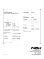
SRM-80A SPECIFICATIONS
OPERATING VOLTAGE
90 to 140 VAC ("E" version 180 to 280 VAC)
LINE IN/OUT
Input Impedances:
Source
A Input
B Input
C Input
D Input
Output Impedances:
A Output
To Power Amp
B,C,D Output:
Sensitivity for 0 VU:
MONITOR OUTPUTS
Noise:
56 ohms
THD + N:
0.001% with 750mW driving a 150 ohm load.
POWER AMP
24 Kohms
24 Kohms
40 Kohms
40 Kohms
40 Kohms
Output Impedance:
50 ohms
Connectors:
1/4” TRS balanced
SPEAKER OUTPUT SWITCHING 8A/240V
Connectors:
50 ohms
50 ohms
<50 ohms
Power amp and speaker
connectors: 5-way binding
posts
METERS
Accuracy:
0 dBu (.775 Vrms)
or +4 dBu (1.23 Vrms)
Max. Through Input Level: +21 dBu (8.7 Vrms)
Max. Output Level:
Output Impedance:
+27dBu (17.34Vrms)
±0.5 dB
MECHANICAL
Dimensions:
NOTES
1.75” H x 19” W x 6.625”
D. Weight: 6 lbs (2.7 kg)
0 dBu equals .775 Vrms
<-95dBu, 20Hz to 20kHz.
THD + N:
0.003% maximum
Crosstalk:
-83dB minimum @ 10kHz
Connectors:
Balanced TRS input and
output jacks sends. RCA
jacks for “B”, “C”, and “D”
inputs and outputs.
HEADPHONE OUTPUT
Specifications subject to change without notice
0003-082703-B
Furman Sound, Inc.
1997 South McDowell Blvd.
Petaluma, California 94954-6919 USA
Phone: 707-763-1010
Fax: 707-763-1310
Web: www.furmansound.com
E-mail: [email protected]