1
FUJITSU PCI GigabitEthernet 3.0 Update1
for Solaris TM Operating System
User's Guide
For Safe Operation
Handling of This Manual
This manual contains important information regarding the use and handling of this product. Read this
manual thoroughly. Pay special attention to the section "Important Warnings". Use the product according
to the instructions and information available in this manual.
FUJITSU makes every effort to prevent users and bystanders from being injured or from suffering from
damages to their property. Use the product according to this manual.
Documents produced by FUJITSU may contain technology controlled under the Foreign Exchange and
Foreign Trade Control Law of Japan. The document which contains such technology should not be exported
from Japan or transferred to anyone other than residents of Japan without first obtaining license from the
Ministry of International Trade and Industry of Japan in accordance with the above law.
TRADEMARK ACKNOWLEDGMENTS
● FUJITSU and the FUJITSU logo are trademarks of Fujitsu Limited.
● UNIX is a registered trademark of The Open Group in the United States and other countries.
● Sun, Sun Microsystems, the Sun Logo, Solaris and all Solaris based marks and logos are
trademarks or registered trademarks of Sun Microsystems, Inc. in the U.S. and other countries, and
are used under license.
● All other product names mentioned herein are trademarks or registered trademarks of their
respective owners.
● The contents of this manual shall not be disclosed in any way or reproduced in any media without
the express written permission of Fujitsu Limited.
i
Revision History
Edition
01
02
03
ii
Date
2003-2-20
2003-5-1
2004-1-8
Revised section (*1)
(Added/Deleted/Altered)
Details
-
-
Appendix D
PRIMEPOWER1/100 is added
3.4
Change the procedure
3.3.1
Some parameter explanations are added
3.5
Some procedures are added
3.6
VLAN information is added
-
Change the Version 2.0 to 2.1
Appendix E
VLAN tested switches are added
Chapter 4
LinkAggregation function is added
-
Change the Version 2.1 to 2.2
Appendix A
Messages are added
04
2004-10-28
Appendix E
Switches are added
05
2005-11-11
-
Change the Version 2.2 to 2.3
06
2006-02-06
-
Change the Version 2.3 to 2.4
07
2007-01-20
-
Change the Version 2.4 to 3.0
08
2007-04-03
-
Change the Version 3.0 to 3.0 Update1
Preface
Purpose
This manual describes how to install the FUJITSU PCI GigabitEthernet card in your PRIMEPOWER
system, and configure the environment setting of the interface.
Target Reader
This book is intended for system administrators responsible for installing the FUJITSU PCI
GigabitEthernet card.
To understand the concepts and procedures presented in this manual, you need from one to two years of
experience in the Solaris (TM) Operating System (in this document, abbreviated to Solaris OS.) system
administration and a basic knowledge of networked systems.
Organization
This section describes the chapters in this document.
Chapter 1 Product Outline
Chapter 1 describes the distinctive features of the FUJITSU PCI GigabitEthernet Card.
Chapter 2 Installing FUJITSU PCI GigabitEthernet Card
Chapter 2 describes how to install the adapter.
Chapter 3 Setting Configuraton Information
Chapter 3 provides an overview of the environment definition.
Chapter 4 LinkAggregation Feature
Chapter 4 describes how to use the LinkAggregation function.
Chapter 5 Troubleshooting
Chapter 5 offers suggestions about how to troubleshoot and resolve problems you might encounter
during installation.
Appendix A Messages
Appendix A shows the messages output by the driver software.
Appendix B On-Board Diagnostics
Appendix B shows details of the adapter’s on-board diagnostics.
Appendix C Using GigabitEthernet in a Cluster Environment
Appendix C describes notes when using the adapter in a Cluster System.
Appendix D PCI Slot Number and Device Name
Appendix D shows the PCI slot number and device name list matrix for each PRIMEPOWER
model.
Appendix E Available Switches
Appendix E shows a list of the available and supported switches.
8th Edition: April 2007
Symbol
The following conventions are used in this manual:
●
●
Items that require attention are explained.
Useful information is given.
Attention
● The contents of this manual may be revised without prior notice.
iii
iv
Contents
Chapter 1
Product Outline ....................................................................... 1
1.1 Key Features ................................................................................. 2
1.2 GigabitEthernet card Specifications .......................................................... 3
1.2.1 Specifications ........................................................................... 3
1.2.2 Part Names and Features of Hardware ...................................................... 4
Chapter 2
Installing FUJITSU PCI GigabitEthernet Card ........................................... 9
2.1 Installation of the GigabitEthernet Card .................................................... 10
2.2 Identifying the GigabitEthernet Card ........................................................ 11
2.3 Cable Connection ............................................................................ 12
Chapter 3
Setting Configuration Information .................................................... 21
3.1 Driver Software Installation ................................................................ 22
3.2 Environment Setting ......................................................................... 23
3.2.1 Configuring the Hostname File ........................................................... 23
3.2.2 Hostname Definition ..................................................................... 23
3.2.3 Netmask Value Definition ................................................................ 25
3.3 Operation Mode Setup ........................................................................ 26
3.3.1 The fjgi.conf File ...................................................................... 26
3.3.2 JumboFrame Setup ........................................................................ 29
3.3.3 The ndd Utility ......................................................................... 32
3.3.4 FCode Settings .......................................................................... 36
3.4 Discernment Of the GigabitEthernet Interface ................................................ 39
3.4.1 Discernment Of the GigabitEthernet Interface on PRIMEPOWER or GP7000 family ............. 39
3.4.2 Discernment Of the GigabitEthernet Interface on SPARC Enterprise ........................ 40
3.5 Network Installation ........................................................................ 42
3.6 VLAN Interface Setup ........................................................................ 45
3.6.1 IEEE 802.1Q TagVLAN Description ......................................................... 45
3.6.2 Setting Up the VLAN Interface ........................................................... 45
Chapter 4
LinkAggregation Feature .............................................................. 47
4.1 About LinkAggregation Feature ............................................................... 48
4.2 Configuration of the LinkAggregation Feature ................................................ 50
4.2.1 Setting Up the /etc/opt/FJSVla/config File .............................................. 50
4.2.2 Using the /etc/opt/FJSVla/bin/fjla Command .............................................. 52
4.2.2.1 Activate a LinkAggregation Group (fjla init) ........................................ 52
4.2.2.2 Inactivate a LinkAggregation Group (fjla term) ...................................... 53
4.2.2.3 Display Status and Statistics (fjla stat) ........................................... 54
4.3 Notes ....................................................................................... 56
Chapter 5
Troubleshooting ...................................................................... 57
Appendix A
Messages ............................................................................. 59
A.1 Console Messages............................................................................ 59
A.2 Command Messages............................................................................ 63
Appendix B
On-Board Diagnostics ................................................................. 65
v
Contents
Appendix C
Using GigabitEthernet in a Cluster Environment ....................................... 71
C.1 Cluster Environment Support................................................................. 71
C.2 Cluster Environment Setup Procedure......................................................... 71
C.3 Notes....................................................................................... 72
Appendix D
PCI Slot Number and Device Name ...................................................... 73
Appendix E
Available Switches .................................................................. 107
vi
Chapter 1 Product Outline
The following topics are described in this chapter.
● Key Features
● GigabitEthernet card Specifications
Chapter 1 Product Outline
1.1 Key Features
The FUJITSU GigabitEthernet card is a adapter designed for Solaris OS servers that are
connected to a GigabitEthernet network. This card offers the physical services and data
link services defined by IEEE802.3.
Table 1.1 GigabitEthernet function
Main Function
IEEE802.3 compliant 1000Base-SX(PW008GE4, PW0G8GE1), 1000Base-SX * 2ports(SE0X7GD2X),
10/100/1000Base-T(PW008GE5, PW0G8GE2, PRIMEPOWER250/450 secondary LAN ), 10/100/1000
Base-T * 2ports(SE0X7GD1X), 10/100/1000 Base-T * 4ports(PW008QG1, SE0X7GQ1X)
JumboFrame function*
ndd(1M) command provided by Solaris OS
VLAN* (IEEE 802.3 TagVLAN)
LinkAggregation* (IEEE 802.3 except dynamic LACP protocol)
IPv4/IPv6
SNA/FNA
*JumboFrame, VLAN and LinkAggregation functions are supported after Solaris 8 OS.
* JumboFrame Functionality
Although the maximum frame size (MTU) of one Ethernet packet is 1514 bytes, by using a JumboFrame
function it becomes possible to set MTU from 1514 bytes to 9014 bytes. Use of JumboFrames can
mitigate the CPU load and improve transmission speed.
* Point to Point Connection
Direct connection between FUJITSU PCI GigabitEthernet cards is forbidden, except when used in
the private LAN of a CLUSTER system.
2
1.2 GigabitEthernet card Specifications
1.2 GigabitEthernet card Specifications
The FUJITSU PCI GigabitEthernet card is an adapter that is installed into a PCI slot or
a PCI Express slot.
1.2.1 Specifications
The specification of the FUJITSU PCI GigabitEthernet adapter is listed in "Table 1.2.1
PCI GigabitEthernet Card Specification" and "Table 1.2.2 PCI Express GigabitEthernet Card
Specification".
Table 1.2.1 PCI GigabitEthernet Card Specification
Item
Compatibility
Host Bus Interface
PCI Local Bus Revision 2.1 or later
Network Interface
1000Base-SX (PW008GE4, PW0G8GE1)
10/100/1000Base-T (PW008GE5, PW0G8GE2, PRIMEPOWER250/450 secondary
LAN)
10/100/1000Base-T * 4ports(PW008QG1)
Host Data Transfer
32/64-bit Bus Mastering DMA Transfers
Bus Type
One PCI slot per card.
Power Requirements
Maximum: 4.7W(PW008GE4/5, PW0G8GE1/2), 14.0W(PW008QG1)
Connections
1000Base-SX (P008GE4, PW0G8GE1): Multi-mode Fibre (62.5/125 micron)
SC-Duplex
10/100/1000Base-T (PW008GE5, PW0G8GE2, PRIMEPOWER250/450 secondary
LAN, PW008QG1): Cat5e Cable (Cat5 cable can also be used for
10/100Mbps.)
Table 1.2.2 PCI Express GigabitEthernet Card Specification
Item
Compatibility
Host Bus Interface
PCI Express 1.0a (SE0X7GD1X, SE0X7GD2X)
PCI Express 1.1 (SE0X7GQ1X)
Network Interface
1000Base-SX * 2ports (SE0X7GD2X)
10/100/1000Base-T * 2ports (SE0X7GD1X)
10/100/1000Base-T * 4ports (SE0X7GQ1X)
Host Data Transfer
SE0X7GD1X, SE0X7GD2X: PCI Express 4lane Bus Mastering DMA Transfers
SE0X7GQ1X:
PCI Express 8lane Bus Mastering DMA Transfers
Bus Type
One PCI slot per card.
Power Requirements
Maximum: 9.1W(SE0X7GD1X), 9.2W(SE0X7GD2X), 15.0W(SE0X7GQ1X)
Connections
1000Base-SX(SE0X7GD2X):
Multi-mode Fibre
(LC-SC: 62.5/125 micron and 50/125 micron
(A card side is LC. It is used when connection place partner
equipment is SC.),
LC-LC: 62.5/125 micron and 50/125 micron)
10/100/1000Base-T (SE0X7GD1X, SE0X7GQ1X):
Cat5e Cable (Cat5 cable can also be used for 10/100Mbps.)
● PW008GE4, PW0G8GE1 and SE0X7GD2X only supports full duplex connection. Half-duplex
3
Chapter 1 Product Outline
connection is not supported.
● When using 1000Mbps transfer rate with PW008GE5, PW0G8GE2, PRIMEPOWER250/450
secondary LAN port, SE0X7GD1X, PW008QG1 and SE0X7GQ1X, only Auto-Negotiation=On can
be used.
1.2.2 Part Names and Features of Hardware
Figure 1.1 to 1.8 shows the appearance of the FUJITSU PCI GigabitEthernet adapters. The
part names and features are listed as follows.
Connection:
PW008GE4, PW0G8GE1 and SE0X7GD2X allow optical fibre cable connection, PW008GE5, PW0G8GE2,
PRIMEPOWER250/450 secondary LAN port, SE0X7GD1X, PW008QG1 and SE0X7GQ1X allow twisted pair
cable connection. See the section "Chapter 2 Installing FUJITSU PCI GigabitEthernet Card"
for detailed information.
LEDs:
PW008GE4 (1000BASE-SX) has two LEDs(1000M LED, ACT LED) indicating transmission rate and
activity. PW0G8GE1 and SE0X7GD2X (1000BASE-SX) has two LEDs(LINK LED, ACT LED) indicating
transmission rate and activity. PW008GE5 and PW0G8GE2 (10/100/1000BASE-T) have four
LEDs(1000M LED, 100M LED, 10M LED, ACT LED) indicating 1000Mbps, 100Mbps, 10Mbps, and
activity. SE0X7GD1X (10/100/1000BASE-T) have three LEDs(1000M LED, 100M LED, LINK/ACT LED)
indicating 1000Mbps, 100Mbps, and activity. PW008QG1 and SE0X7GQ1X (10/100/1000BASE-T)
has two LEDs(LINK LED, ACT LED) indicating transmission rate and activity. See "Appendix
B On-Board Diagnostics" for detailed information.
4
1.2 GigabitEthernet card Specifications
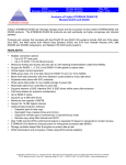
Figure 1.1 1000Base-SX
(PW008GE4)
Figure 1.2 10/100/1000Base-T
(PW008GE5)
Figure 1.3 1000Base-SX
(PW0G8GE1)
Figure 1.4 10/100/1000Base-T
(PW0G8GE2)
5
Chapter 1 Product Outline
Figure 1.5 1000Base-SX * 2ports
(SE0X7GD2X)
6
Figure 1.6 10/100/1000Base-T * 2ports
(SE0X7GD1X)
1.2 GigabitEthernet card Specifications
Figure 1.7 10/100/1000Base-T * 4ports
(PW0G8GE1)
Figure 1.8 10/100/1000Base-T * 4ports
(SE0X7GQ1X)
7
Chapter 2 Installing FUJITSU PCI
GigabitEthernet Card
This chapter describes the tasks necessary to install this card in the main unit.
● Installation of the GigabitEthernet card
● Identifying the GigabitEthernet card
● Cable connection
Chapter 2 Installing FUJITSU PCI GigabitEthernet Card
2.1 Installation of the GigabitEthernet Card
Insert the card in a PCI slot or a PCI Express slot on the main unit.
(Please refer to the main unit’s User’s Manual for details about installing cards and
specific PCI slot or PCI Express slot specifications.)
10
2.2 Identifying the GigabitEthernet Card
2.2 Identifying the GigabitEthernet Card
The GigabitEthernet card can be identified by executing the "boot -r" command at the
OpenBoot prompt.
ok boot -r
11
Chapter 2 Installing FUJITSU PCI GigabitEthernet Card
2.3 Cable Connection
To connect the PW008GE4, PW0G8GE1 and SE0X7GD2X GigabitEthernet card to the network, use
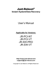
an optical fiber cable. To connect the PW008GE5, PW0G8GE2, PRIMEPOWR250/450 secondary LAN,
PW008QG1, SE0X7GD1X and SE0x7GQ1X GigabitEthernet card to the network, use a CAT5E twisted
pair cable (Enhanced Category 5).
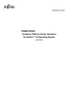
Figure 2.3.1 PW008GE4 (with Optical Fiber Cable)
12
2.3 Cable Connection
Figure 2.3.2 PW008GE5 (with Twisted Pair Cat5E Cable)
13
Chapter 2 Installing FUJITSU PCI GigabitEthernet Card
Figure 2.3.3 PW0G8GE1 (with Optical Fiber Cable)
14
2.3 Cable Connection
Figure 2.3.4 PW0G8GE2 (with Twisted Pair Cat5E Cable)
15
Chapter 2 Installing FUJITSU PCI GigabitEthernet Card
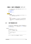
Figure 2.3.5 SE0X7GD2X (with Optical Fiber Cable)
16
2.3 Cable Connection
Figure 2.3.6 SE0X7GD1X (with Twisted Pair Cat5E Cable)
17
Chapter 2 Installing FUJITSU PCI GigabitEthernet Card
Figure 2.3.7 PW008QG1 (with Twisted Pair Cat5E Cable)
18
2.3 Cable Connection
Figure 2.3.8 SE0X7GQ1X (with Twisted Pair Cat5E Cable)
19
Chapter 3 Setting Configuration
Information
This chapter describes how to set configuration information after installing the FUJITSU
PCI GigabitEthernet interface.
The following topics are covered in this chapter:
● Driver Software Installation
● Environment Setting
● Operation Mode Setup
● Discernment of the GigabitEthernet interface
● Network Installation
● VLAN Interface Setup
Chapter 3 Setting Configuration Information
3.1 Driver Software Installation
To make use of the FUJITSU PCI GigabitEthernet interface, Solaris OS version-specific
driver packages must be installed from the attached CD-ROM. See the document "Installation
Guide FUJITSU PCI GigabitEthernet 3.0 Update1" for the installation procedure.
22
3.2 Environment Setting
3.2 Environment Setting
This section explains how to edit the necessary file to configure the operating environment
of the FUJITSU PCI GigabitEthernet interface.
In TCP/IP (IPv4 or IPv6) protocol, edit the following information must be setup.
● Configuring the Hostname file
● Hostname Definition
● Netmask Value Definition
3.2.1 Configuring the Hostname File
1. To use the GigabitEthernet interface as an IPv4 interface:
Allocate an IP address or hostname for the fjgi driver by editing the
/etc/hostname.fjgi* file (where * is a numerical value). About netmask value, please
see "3.2.3 Netmask Value Definition".
Example /etc/hostname.fjgi* file:
Define a unique hostname:
giga-v4
Or define the IP address:
192.168.150.1
Note 1: Please put a decimal number (instance number) into *.
See section "3.4 Discernment Of the GigabitEthernet Interface" for detailed
information about instance number.
Note 2: See section "3.2.2 Hostname Definition" for detailed information about
defining the hostname.
Note 3: Please put in neither a blank nor a empty line behind an IP address. If a
blank or a empty line enter, it will not be activated at the time of main part
equipment starting.
2. To use the GigabitEthernet interface as an IPv6 interface:
Allocate an IP address and prefix for the fjgi driver by editing the
/etc/hostname6.fjgi* file (where * is a numerical value).
Example /etc/hostname6.fjgi* file:
Define a unique hostname:
addif giga-v6/120 up
Note: See section "3.2.2 Hostname Definition" for detailed information about
defining the hostname.
3. To use the GigabitEthernet interface as a VLAN interface:
See section "3.6.2 How to create the VLAN interface", and after defining the VLAN
name, follow steps 1 or 2 above.
3.2.2 Hostname Definition
Define an IP address with a unique hostname.
1. To use the GigabitEthernet interface as an IPv4 interface:
Add the IPv4 address and hostname to the /etc/hosts file.
23
Chapter 3 Setting Configuration Information
Example /etc/hosts file:
# IP Address
190.168.150.1
24
Hostname
giga-v4
3.2 Environment Setting
2. To use the GigabitEthernet interface as an IPv6 interface:
Add the IPv6 address and hostname to the /etc/inet/ipnodes file.
Example /etc/inet/ipnodes file:
# IP Address
Hostname
fe80::2e0:ff:fea6:2222
giga-v6
3.2.3 Netmask Value Definition
To use the GigabitEthernet interface as an IPv4 interface, add the netmask value and IP
address to the /etc/netmasks file.
Example /etc/netmasks file:
# IP Address
netmask
192.168.150.0
255.255.255.0
25
Chapter 3 Setting Configuration Information
3.3 Operation Mode Setup
This section explains how to edit the fjgi.conf configuration file or issue a command to
change the operation mode of the FUJITSU PCI GigabitEthernet interface. The operation mode
can be changed with the following:
● The fjgi.conf file
● JumboFrame Setup
● The ndd Utility
● FCode Settings
3.3.1 The fjgi.conf File
About speed/duplex/flowcontrol, it recommends carrying out default operation (automatic
setup by Auto-Negotiation). Usually, a setup of a fjgi.conf file is unnecessary.
It is a case as shown in the following examples that a setup of a fjgi.conf file is needed.
Example
● When connection partner equipment is not supporting Auto-Negotiation
In this case, please let mode of operation in agreement with self-equipment and
connection place partner equipment.
● Although Auto-Negotiation is used, when it is necessary to make only a specific
setting value into a different value from a default value (for example, when you
want to set speed as 100Mbps, in order to press down the CPU load by the network
low)
● When JumboFrame is used
It is also possible to set up except fjgi.conf. For details, please refer to "3.3.2
JumboFrame Setup".
The following table provides descriptions of the parameters used in the fjgi.conf file
to configure the GigabitEthernet interface.
When editing the fjgi.conf file, please review the [Caution] items below.
[Parameter List]
Parameter
Description
Name
fjgi *1
Used to specify the driver name.
Parent
See below
Used to specify the location of the device
node in the device tree.
unit-address
See below
Used to specify the address within the device
node.
Sense
First connection is attempted with
AutoNegotiation_A=On. If this fails, the
connection is retried with
AutoNegotiation_A=Off automatically.
This setting can be used only with PW008GE4
or PW0G8GE1.
On (default)
Auto-Negotiation is enabled. The interface
will not be able to communicate with remote
device operating in fixed mode
(Auto-Negotiation disabled).
When PW008GE5, PW0G8GE2, SE0X7GD1X,
PW008QG1, SE0X7GQ1X or PRIMEPOWER250/450
secondary LAN port is used in 1000Mbps mode,
use this setting.
AutoNegotiation_A
26
Value
3.3 Operation Mode Setup
Parameter
LinkSpeed_A
FlowControl_A
Auto (default)
Connection speed of 1000, 100, or 10 Mbps is
set based on negotiation with the remote
device.
(This can only be set when
AutoNegotiation_A=On.)
1000
Connect at 1000Mbps.
100
Connect at 100Mbps.
10
Connect at 10Mbps.
Both (default)
Indicating that both Full-Duplex and
Half-Duplex are being supported.
(This can only be set when
AutoNegotiation_A=On.)
Half
Half-Duplex operation is allowed.
Full
Full-Duplex operation is allowed.
Auto (default)
Flow control is performed according to a setup
of partner equipment.
Rem
Only flow control from the remote machine is
allowed. Flow control to the remote machine
is not allowed.
LocSend
Only flow control from the main unit is
allowed. Flow control from the remote machine
is not allowed.
None
Flow control is disabled.
Auto (default)
Master or Slave is set based on negotiation
with the remote device.
(This can only be set when AutoNegotiation_A=
On.)
Master
Communication by Master.
Slave
Communication by Slave.
1500 to 9000
MTU size is specified.
*2
*3
*4
fjgi_mtu
*5
Description
Auto-Negotiation is disabled. (Fixed mode)
*2
DuplexCapabilities_A
Role_A
Value
Off
*1: When PW008GE5 or PW0G8GE2 is used, it is possible to set name="FJSV,pgtb". When PW008GE4
or PW0G8GE1 is used, it is possible to set name="FJSV,pgsb". It becomes the same meaning
as having specified name="fjgi" in both cases.
*2: Parameter is supported on 10/100/1000Base-T (PW008GE5, PW0G8GE2, SE0X7GD1X, PW008QG1,
SE0X7GQ1X) adapters and PRIMEPOWER250/450 secondary LAN port.
*3: Parameter is effective only when AutoNegotiation_A=On. When AutoNegotiation_A=Off, with
10/100/1000 Base-T, it becomes FlowControl_A=None. And with 1000 Base-SX, it becomes
FlowControl_A=Rem.
*4: Parameter is supported on 10/100/1000Base-T (PW008GE5, PW0G8GE2, SE0X7GD1X, PW008QG1,
SE0X7GQ1X) adapters and PRIMEPOWER250/450 secondary LAN port in 1000Mbps mode only.
*5: Parameter is supported only in Solaris 9 or later, and when the following patch for PRIMEPOWER
is applied.
In the case of Solaris 9 OS: 114994-13 or later
In the case of Solaris 10 OS: 120462-06 or later
[Parameter Setting]
The following shows how to set the parent and unit-address parameter in the fjgi.conf file.
● Find the fjgi device tree, device node and instance number in the /etc/path_to_inst
27
Chapter 3 Setting Configuration Information
file.
example)
# grep fjgi /etc/path_to_inst
"/pci@83,2000/FJSV,pwga@1" 0 "fjgi"
"/pci@15,2000/FJSV,pgtb@1" 1 "fjgi"
"/pci@17,2000/FJSV,pgsb@1" 2 "fjgi"
"/pci@83,4000/pci@3/FJSV,p4ta@1" 3
"/pci@83,4000/pci@3/FJSV,p4ta@1,1"
"/pci@83,4000/pci@3/FJSV,p4ta@3" 5
"/pci@83,4000/pci@3/FJSV,p4ta@3,1"
- PRIMEPOWER250/450 secondary LAN port
- PW008GE5, PW0G8GE2
- PW008GE4, PW0G8GE1
"fjgi"
4 "fjgi"
"fjgi"
6 "fjgi"
PW008QG1
● In the above example:
device node of device tree
instance number
driver name
/pci@83,2000/FJSV,pwga@1
0
fjgi
/pci@15,2000/FJSV,pgtb@1
1
fjgi
/pci@17,2000/FJSV,pgsb@1
2
fjgi
/pci@83,4000/pci@3/FJSV,p4ta@1
3
fjgi
/pci@83,4000/pci@3/FJSV,p4ta@1,1
4
fjgi
/pci@83,4000/pci@3/FJSV,p4ta@3
5
fjgi
/pci@83,4000/pci@3/FJSV,p4ta@3,1
6
fjgi
● The unit-address is the number to the right of FJSV,pwga@, FJSV,pgtb@, or FJSV,pgsb@.
The unit-addresses from the example are shown below.
PRIMEPOWER250/450
secondary LAN port
PW008GE5,
PW0G8GE2
PW008GE4,
PW0G8GE1
name
fjgi
fjgi
fjgi
parent
/pci@83,2000
/pci@15,2000
/pci@17,2000
unit-address
1
1
1
PW008QG1
name
fjgi
parent
/pci@83,2000/pci@3
unit-address
instance
instance
instance
instance
3
4
5
6
is
is
is
is
1
1,1
3
3,1
― The location of the fjgi.conf file depends on the model of the host system
as described below:
(1) PRIMEPOWER1 or PRIMEPOWER100
/platform/sun4u/kernel/drv/fjgi.conf
(2) PRIMEPOWER other than (1) or GP7000 family
/platform/sun4us/kernel/drv/fjgi.conf
(3) SPARC Enterprise T1000 or T2000
/platform/sun4v/kernel/drv/fjgi.conf
(4) SPARC Enterprise M4000,M5000,M8000 or M9000
/platform/SUNW,SPARC-Enterprise/kernel/drv/fjgi.conf
28
3.3 Operation Mode Setup
― The example which sets a parameter to a fjgi.conf file is shown.
example 1. the case where use the card of PW008GE5 (10/100-/1000BASE-T), and
disable Auto-Negotiation and connection speed is made into 100Mbps and
Half-Duplex
name="fjgi" parent="/pci@15,2000" unit-address="1"
AutoNegotiation_A="Off" LinkSpeed_A="100" DuplexCapabilities_A="Half" ;
example 2. the case where use the card of PW008GE4 (1000BASE-SX) and
Auto-Negotiation is disabled
name="fjgi" parent="/pci@17,2000" unit-address="1"
AutoNegotiation_A="Off" ;
example 3. the case where use the port of the instance number 4 of PW008QG1
(10/100-/1000BASE-T), and enable Auto-Negotiation and connection speed is
made into 100Mbps and a Full-Duplex
name="fjgi" parent="/pci@83,4000/pci@3" unit-address="1,1"
AutoNegotiation_A="On" LinkSpeed_A="100" DuplexCapabilities_A="Full" ;
After making changes to the fjgi.conf file, the system must be rebooted.
● About speed/duplex/flowcontrol, it recommends carrying out default operation
(Auto-Negotiation). In that case, connection partner equipment should also enable
Auto-Negotiation. By doing so, it is the optimal.
speed/duplex/flow control
It
is set up automatically.
● When you use fjgi.conf file and you change mode of operation, please let mode of
operation in agreement with self-equipment and connection partner equipment. When
mode of operation is not in agreement with self-equipment and connection partner
equipment, it may not become a value as a link up is not carried out, or it cannot
communicate even if it carries out a link up, or mode of operation specified.
● When an adapter is removed, please remove the setting parameters of the applicable
adapter defined in the fjgi.conf file. If an adapter is removed and the setting
parameters are left in the fjgi.conf file, panic may occur at the time of a system
startup, and it becomes impossible to start.
● Because the parameters are set in the fjgi.conf file per physical interface, when
a VLAN interface is used, individual interface used by the VLAN interface must be
similarly configured.
● The parameters set in the fjgi.conf file may not become effective with DR(Dynamic
Reconfiguration) function and Pci Hot Plug function. The system must be rebooted
after the parameters are set.
29
Chapter 3 Setting Configuration Information
3.3.2 JumboFrame Setup
By using a JumboFrame the TCP/IP MTU size can be expanded from 1500 to 9000. By expanding
the single packet transmission size, the number of packets processed can be reduced,
lowering the CPU load.
There are three kinds of following methods in the setting procedure of JumboFrame.
[Method 1: How to specify by /etc/system and /etc/hostname.fjgi*
(recommendation)]
It recommends setting up JumboFrame by this method. This method can be used only
in Solaris 9 or later, or Solaris 8 patch 109900-01 or later is applied. When
you use JumboFrame in Solaris 2.6 or 7, please set up by the method 2.
1. Add the following line to /etc/system file.
set fjgi:fjgi_jumbo=1
2. The MTU size of TCP/IP is set up by describing MTU size in /etc/hostname.fjgi*
(notes) in the form of the following between 1500 and 9000 and rebooting. When
not specifying an MTU value as this file, it is set as a default value (except
for a 9000Byte MAC header).
(Note) * expresses an instance number.
Setting formal
hostname mtu MTU size
Example of setting (when setting MTU size of fjgi0 to 8000)
# cat/etc/hostname.fjgi0
myhost mtu 8000
#
3. Reboot the system.
[Method 2: How to specify by /etc/system and /etc/fjmtu.fjgi*]
Please use this method when you use JumboFrame in Solaris 2.6 or 7. This method
is not supported when main part equipment is SPARC Enterprise Server series.
1. Add the following line to /etc/system file.
set fjgi:fjgi_jumbo=1
30
3.3 Operation Mode Setup
2. The MTU size of TCP/IP is set up by creating /etc/fjmtu.fjgi* (notes) and
describing MTU size in /etc/fjmtu.fjgi* in the form of the following between
1500 and 9000 and rebooting. When not specifying an MTU value as this file,
it is set as a default value (except for a 9000Byte MAC header).
(Note) * expresses an instance number. An instance number should set up the
value (the same as that of * of /etc/hostname.fjgi*) which surely corresponds.
Example of setting (when setting MTU size of fjgi0 to 8000)
# cat /etc/fjmtu.fjgi0
8000
#
3. Reboot the system.
[Method 3: How to specify by fjgi.conf]
When you set up MTU size separately by every interface, and when application does
not refer to /etc/hostname.fjgi* (example . CF of PRIMECLUSTER, CIP function),
please use this method.
This method can be used only in Solaris 9 or later, and when the following patch
for PRIMEPOWER is applied.
In the case of Solaris 9 OS: 114994-13 or later
In the case of Solaris 10 OS: 120462-06 or later
1. Add fjgi_mtu parameter to fjgi.conf file. Specify the value like fjgi_mtu=8000
instead of the character string like fjgi_mtu="8000".
Example of file description (when setting MTU size of a specific interface to 8000)
name="FJSV,pgtb" parent="/pci@15,2000" unit-address="1"
fjgi_mtu=8000;
2. Reboot the system.
● If JumboFrame support is enabled, the interface will be unable to transmit and
receive data in IEEE802.3 format.
● In the case of a method 1 or a method 2, if two or more interfaces, or VLAN interfaces
are installed, the JumboFrame setting applies to all interfaces.
● When the file transfer protocol (FTP) is used, set the MTU-size to 8232 or less.
● When using the JumboFrames function with the PW008GE5, PW0G8GE2, SE0X7GD1X,
PW008QG1, SE0X7GQ1X or the PRIMEPOWER250/450 secondary LAN port, only use 1000Mbps
mode.
31
Chapter 3 Setting Configuration Information
● The parameters set in /etc/fjmtu.fjgi* and fjgi.conf file are not effective with
DR(Dynamic Reconfiguration) function and Pci Hot Plug function. To be effective this
file, the system must be rebooted.
3.3.3 The ndd Utility
By using the ndd command, the interface communication mode can be changed dynamically.
Usually, although it is not necessary to change the interface communication mode by the
ndd command, when shown in the following examples, please change the interface
communication mode by the ndd command.
Example
― It changed into the equipment which does not support Auto-Negotiation from
the equipment which supports Auto-Negotiation for connection partner
equipment after a system startup. Or it changed into the equipment which
supports Auto-Negotiation from the equipment which does not support
Auto-Negotiation conversely.
● The following examples show how to display and set the parameters using the ndd
command.
Setup of an instance number:
ndd
-set /dev/fjgi 'instance'
value
example) fjgi2 is specified.
# ndd
-set
/dev/fjgi
'instance'
(Instance number "value" of an applicable
interface is specified.)
2
(Note) carry out for referring to -- carry out for setting up -- it is necessary
to specify the instance number of an applicable fjgi interface first
To display:
ndd
-get /dev/fjgi 'param'
(param: Each parameter)
example) The state of the link of fjgi2 is referred to.
# ndd
# ndd
-set
-get
/dev/fjgi
/dev/fjgi
'instance'
2
'link_status'
To set:
ndd
-set /dev/fjgi 'param'
value
(param:each parameter and value: Value)
example) 1000Mbps/FullDuplex of fjgi2 is disabled.
# ndd
-set
/dev/fjgi
'instance'
2
# ndd
-set
/dev/fjgi
' adv_1000fdx_cap'
0
(Note) In this stage, a setup is not reflected in hardware yet.
When setting change is reflected (with no change of an Auto-Negotiation value):
32
3.3 Operation Mode Setup
ndd
-set /dev/fjgi 'instance'
value
ndd
ndd
-set /dev/fjgi 'param1'
-set /dev/fjgi 'param2'
:
ndd
-set /dev/fjgi 'adv_autoneg_cap'
ndd
-set /dev/fjgi 'adv_autoneg_cap'
value
value
(Instance number "value" of an applicable
interface is specified.)
(Change 1 of a setup)
(Change 2 of a setup)
:
N (Once let Auto-Negotiation be a different
value from the present condition.)
M (Auto-Negotiation is returned to the
original value.)
example) While Auto-Negotiation had been enabled, when changing fjgi0 into 100Half
(Autonego=1, link_sppd=100, link_mode=0) from a default state (Autonego=1,
link_speed=1000, link_mode=1)
#
#
#
#
#
#
ndd
ndd
ndd
ndd
ndd
ndd
-set
-set
-set
-set
-set
-set
/dev/fjgi
/dev/fjgi
/dev/fjgi
/dev/fjgi
/dev/fjgi
/dev/fjgi
'instance'
0
'adv_1000fdx_cap'
'adv_1000hdx_cap'
'adv_100fdx_cap'
'adv_autoneg_cap'
'adv_autoneg_cap'
0
0
0
0
1
(Note) Please perform change and sending back of Auto-Negotiation at the end.
When setting change is reflected (an Auto-Negotiation value being subject to
change):
ndd
-set /dev/fjgi 'instance'
value
ndd
ndd
-set /dev/fjgi 'param1'
-set /dev/fjgi 'param2'
:
ndd
-set /dev/fjgi 'adv_autoneg_cap'
value
value
(Instance number "value" of an
applicable interface is specified.)
(Change 1 of a setup)
(Change 2 of a setup)
:
N (Let Auto-Negotiation be a different value
from the present condition.)
exapmle) When fjgi0 is changed into the state of 100Full where Auto-Negotiation was
disabled, from the state of 100Half (Autonego=1, link_sppd=100,
link_mode=0) where Auto-Negotiation was enabled
# ndd
# ndd
# ndd
-set
-set
-set
/dev/fjgi
/dev/fjgi
/dev/fjgi
'instance'
0
'adv_100fdx_cap'
'adv_autoneg_cap'
1
0
(Note) Please make a change of Auto-Negotiation at the end.
● The following parameters can be used with the ndd command:
parameter
status
?
Read only
meaning
Display parameter list
33
Chapter 3 Setting Configuration Information
parameter
meaning
Read only
0 : Link down
1 : Link up
link_speed
Read only
1000 : 1000Mbps
100 : 100Mbps
10 : 10Mbps
link_mode
Read only
0 : Half Duplex communication
1 : Full Duplex communication
autonego
Read only
0 : Auto-Negotiation is Off.
1 : Auto-Negotiation is On.
Read only
0
1
2
3
cardtype
Read only
0 : SX (PW008GE4/PW0G8GE1/SE0X7GD2X)
1 : T (PW008GE5/PW0G8GE2/SE0X7GD1X/
PW008QG1/SE0X7GQ1X,
PRIMEPOWER250/450 secondary LAN port)
instance
Read and write
Instance Number
adv_10fdx_cap
Read and write
10Mbps/FullDuplex Setting
0 : Invalid
1 : Valid (Default)
adv_10hdx_cap
Read and write
10Mbps/HalfDuplex Setting
0 : Invalid
1 : Valid (Default)
Read and write
100Mbps/FullDuplex Setting
0 : Invalid
1 : Valid (Default)
adv_100hdx_cap
Read and write
100Mbps/HalfDuplex Setting
0 : Invalid
1 : Valid (Default)
adv_1000fdx_cap
Read and write
1000Mbps/FullDuplex Setting
0 : Invalid
1 : Valid (Default)
adv_1000hdx_cap
Read and write
1000Mbps/HalfDuplex Setting
0 : Invalid
1 : Valid (Default)
adv_pauseTX
Read and write
Transmit Pause Frame Setting
0 : Invalid
1 : Valid (Default)
Read and write
Receive Pause Frame Setting
0 : Invalid
1 : Valid (Default)
Read and write
Auto-Negotiation Setting
0 : Auto-Negotiation Off (Fixed mode)
1 : Auto-Negotiation On (Default)
Read and write
Role
Setting
(Not
valid
PW008GE4/PW0G8GE1/SE0X7GD2X)
0 : Slave
1 : Master
2 : Auto (Default)
link_status
flow_control
adv_100fdx_cap
adv_pauseRX
adv_autoneg_cap
adv_role_cap
34
status
: None (flow_control disabled)
: LocSend (Can transmit pause frame only)
: Rem (Can receive pause frame only)
: Sym (Can receive and transmit pause frame)
for
3.3 Operation Mode Setup
parameter
status
meaning
to
Read only
The
link-partner
has
been
set
10Mbps/FullDuplex by Auto-Negotiation.
0 : Invalid
1 : Valid
to
Read only
The
link-partner
has
been
set
10Mbps/HalfDuplex by Auto-Negotiation.
0 : Invalid
1 : Valid
Read only
The
link-partner
has
been
set
to
100Mbps/FullDuplex by Auto-Negotiation.
0 : Invalid
1 : Valid
Read only
The
link-partner
has
been
set
to
100Mbps/HalfDuplex by Auto-Negotiation.
0 : Invalid
1 : Valid
Read only
The
link-partner
has
been
set
to
1000Mbps/FullDuplex by Auto-Negotiation.
0 : Invalid
1 : Valid
Read only
The
link-partner
has
been
set
to
1000Mbps/HalfDuplex by Auto-Negotiation.
0 : Invalid
1 : Valid
Read only
The link-partner has been set to transmit
pause frame by Auto-Negotiation.
0 : Invalid
1 : Valid
Read only
The link-partner has been set to receive pause
frame by Auto-Negotiation.
0 : Invalid
1 : Valid
Read only
The
link-partner
has
been
set
Auto-Negotiate by Auto-Negotiation.
0 : Invalid
1 : Valid
role_cap
Read only
The current Role setting when operating at
1000Mbps.
(Not
valid
for
PW008GE4/PW0G8GE1/SE0X7GD2X)
0 : Slave
1 : Master
jumbo
Read only
0 : JumboFrame support disabled.
1 : JumboFrame support enabled.
lp_10fdx_cap
lp_10hdx_cap
lp_100fdx_cap
lp_100hdx_cap
lp_1000fdx_cap
lp_1000hdx_cap
lp_pauseTX
lp_pauseRX
lp_autoneg_cap
to
● About speed/duplex/flowcontrol, it recommends carrying out default operation
(Auto-Negotiation). In that case, connection partner equipment should also enable
Auto-Negotiation. By doing so, it is the optimal.
speed/duplex/flow control
It
35
Chapter 3 Setting Configuration Information
is set up automatically.
● When you use ndd command and you change mode of operation, please let mode of
operation in agreement with self-equipment and connection partner equipment. When
mode of operation is not in agreement with self-equipment and connection partner
equipment, it may not become a value as a link up is not carried out, or it cannot
communicate even if it carries out a link up, or mode of operation specified.
● Due to the ndd command specification, if two or more processes execute the ndd command
for same driver at the same time, the resulting value will be invalid.
● If the ndd command is issued repeatedly, the fjgi driver's performance may decrease.
● The link_speed, link_mode, autonego, and flow_control parameter values are valid
only when link_status = 1. If link_status = 0, these values are invalid.
● The values of lp_10fdx_cap, lp_10hdx_cap, lp_100fdx_cap, lp_100hdx_cap,
lp_1000fdx_cap, lp_1000hdx_cap, lp_pauseTX, lp_pauseRX, and lp_autoneg_cap
parameter values are valid only when Auto-Negotiation communication is successfully
established. The parameter values are invalid when Auto-Negotiation is disabled or
when Auto-Negotiation communication fails.
● The parameter values set by the ndd command become invalid after reboot.
● An ndd command made to a physical interface that is related to IPv4/IPv6 interface
and SNA/FNA interface will apply to both the physical interface and the VLAN
interface.
3.3.4 FCode Settings
By modifying FCode settings, the adapter communication mode can be changed. Changing the
FCode settings is possible on PW008GE4/PW0G8GE1/SE0X7GD2X/PW008GE5/PW0G8GE2/
SE0X7GD1X/PW008QG1/SE0X7GQ1X and the secondary LAN port of the PRIMEPOWER250/450.
Modifying FCode settings may be needed when Auto-Negotiation is not used for speed, duplex
setting, and flow control, or when the link partner does not support Auto-Negotiation.
FCode changes do not take effect after the OBP reset and netboot is completed.
[FCode Setting Example]
The following example describes how to disable Auto-Negotiation and set the communication
speed of an fjgi interface by modifying the FCode settings.
● Search for the device path for the GigabitEthernet interface at the ok prompt.
(Please refer to chapter 3.4 “Discernment of the GigabitEthernet Interface.)
example) ok show-nets
a) /pci@1f,4000/FJSV,pgtb@5
b) /pci@1f,4000/network@1,1
q) NO SELECTION
Enter Selection, q to quit:
In above example, “a) /pci@1f,4000/FJSV,pgtb@5” represents a PW008GE5 interface.
● Select the device.
example) ok
cd
/pci@1f,4000/FJSV,pgtb@5
● Execute the following command to change the mode into Force mode (speed fixed,
36
3.3 Operation Mode Setup
Auto-Negotiation off) from Auto-Negotiation mode.
Setup to FCode is effective between OBP (Open Boot Prom).
1) The mode which can be set up on PW008GE4/PW0G8GE1/SE0X7GD2X (1000BASE-SX) is
as follows.
Execute the following command to set Full Duplex communication, 1000Mbps.
example) ok transfer-speed=1000
2) The
mode
which
can
be
set
up
on
PW008GE5/PW0G8GE2/SE0X7GD1X/PW008QG1/SE0X7GQ1X
and
PRIMEPOWER250/450
secondary LAN port is as follows.
— Execute the following command to set Full Duplex communication, 100Mbps.
example) ok transfer-speed=100
—
Execute the following command to set Half Duplex communication, 100Mbps.
example) ok transfer-speed=100
example) ok half-duplex
—
Execute the following command to set Full Duplex communication, 10bps.
example) ok transfer-speed=10
—
Execute the following command to set Half Duplex communication, 10Mbps.
example) ok transfer-speed=10
example) ok half-duplex
● Display the current settings.
example) ok
.properties
37
Chapter 3 Setting Configuration Information
The following example shows the current settings of a PW008GE5 card installed in
a PRIMEPOWER600.
{6} ok cd /pci@11,4000/FJSV,pgtb@5
{6} ok .properties
duplex
half
<--*1
transfer-speed
0000000a
<--*2
cabinet-name
Cabinet#0
board-name
Motherboard#1
assigned-addresses
83002810 00000000
82002830 00000000
local-mac-address
00 e0 00 a6 c5 0c
fjgiga-rev
000000c2
product-name
FJSV,pgtb
device_type
network
address-bits
00000030
max-frame-size
00004000
reg
00002800 00000000
03002810 00000000
model
Broadcom,BCM5703C
compatible
fjgi
name
FJSV,pgtb
media-type
1000BASE-T
fcode-rom-offset
00000000
66mhz-capable
fast-back-to-back
devsel-speed
00000001
class-code
00020000
interrupts
00000001
max-latency
00000000
min-grant
00000040
subsystem-id
000011a1
subsystem-vendor-id
000010cf
revision-id
00000002
device-id
000011a1
vendor-id
000010cf
pcibus-name
PCIBUS#G
component-name
01-PCI#5
fru
PCI Slot(PCI#5 at
00100000 00000000 00010000
00110000 00000000 00010000
00000000 00000000 00000000
00000000 00000000 00010000
Motherboard#1)
*1: Displayed only when half-duplex is set.
*2: Displayed only when transfer-speed is set to a specific value.
[10Mbps:0xa, 100Mbps:0x64, 1000Mbps:0x3e8]
Note: *1 and *2 are not displayed in a default configuration.
[Returning to Default FCode Settings]
● To return to default FCode settings, execute the following command from the ok prompt,
or power cycle the system.
ok
38
reset-all
3.4 Discernment Of the GigabitEthernet Interface
3.4 Discernment Of the GigabitEthernet Interface
This section explains how to distinguish the FUJITSU PCI GigabitEthernet interface instance
number, interface type, and which slot the card is installed in.
● Discernment Of the GigabitEthernet Interface on PRIMEPOWER or GP7000 family
● Discernment Of the GigabitEthernet Interface on SPARC Enterprise
3.4.1 Discernment Of the GigabitEthernet Interface on PRIMEPOWER
or GP7000 family
This section explains how to distinguish the FUJITSU PCI GigabitEthernet interface instance
number, interface type, and which slot the card is installed in, on PRIMEPOWER or GP7000
family.
1. To determine the instance number, execute the following command.
# prtconf -D | grep fjgi
example) # prtconf -D | grep
FJSV,pwga, instance
FJSV,pgsb, instance
FJSV,pgtb, instance
FJSV,p4ta, instance
FJSV,p4ta, instance
FJSV,p4ta, instance
FJSV,p4ta, instance
fjgi
#0 (driver
#1 (driver
#2 (driver
#3 (driver
#4 (driver
#5 (driver
#6 (driver
name:
name:
name:
name:
name:
name:
name:
fjgi)
fjgi)
fjgi)
fjgi)
fjgi)
fjgi)
fjgi)
The instance number is the number displayed in bold above.
The adapter type can also be determined from the prtconf command output.
FJSV,pwga
PRIMEPOWER250/450 secondary LAN port
FJSV,pgsb
PW008GE4/PW0G8GE1 (1000BASE-SX) card
FJSV,pgtb
PW008GE5/PW0G8GE2 (10/100/1000BASE-T) card
FJSV,p4ta
PW008QG1 (10/100/1000BASE-T * 4ports) card
2. To determine the slot the GigabitEthernet PCI card is mounted in, execute the
following command.
# more /etc/path_to_inst | grep fjgi
example) # more /etc/path_to_inst | grep fjgi
"/pci@83,2000/FJSV,pwga@1" 0 "fjgi"
"/pci@1f,0/pci@1/FJSV,pgsb@4" 1 "fjgi"
"/pci@1f,0/pci@1/FJSV,pgtb@1" 2 "fjgi"
"/pci@83,4000/pci@3/FJSV,p4ta@1" 3 "fjgi"
"/pci@83,4000/pci@3/FJSV,p4ta@1,1" 4 "fjgi"
"/pci@83,4000/pci@3/FJSV,p4ta@3" 5 "fjgi"
"/pci@83,4000/pci@3/FJSV,p4ta@3,1" 6 "fjgi"
The logical bus address and the instance number (shown in bold, above) are displayed.
The following table shows the logical bus address, instance number, and driver name
for the example output above.
39
Chapter 3 Setting Configuration Information
Logical bus address
Instance number
Driver name
"/pci@83,2000/FJSV,pwga@1"
0
fjgi
"/pci@1f,0/pci@1/FJSV,pgsb@4"
1
fjgi
"/pci@1f,0/pci@1/FJSV,pgtb@1"
2
fjgi
"/pci@83,4000/pci@3/FJSV,p4ta@1"
3
fjgi
"/pci@83,4000/pci@3/FJSV,p4ta@1,1"
4
fjgi
"/pci@83,4000/pci@3/FJSV,p4ta@3
5
fjgi
"/pci@83,4000/pci@3/FJSV,p4ta@3,1
6
fjgi
The logical bus address corresponds to a physical PCI slot number based on the Main
Unit model number. Refer to the "Appendix D PCI slot number and device name" to
determine the slot number from the logical bus address.
3.4.2 Discernment Of the GigabitEthernet Interface on SPARC
Enterprise
This section explains how to distinguish the FUJITSU PCI GigabitEthernet interface instance
number, interface type, and which slot the card is installed in, on SPARC Enterprise.
1. To determine the instance number, execute the following command.
# prtconf -D | grep fjgi
example) # prtconf -D | grep
FJSV,e4ta, instance
FJSV,e4ta, instance
FJSV,e4ta, instance
FJSV,e4ta, instance
FJSV,e2sa, instance
FJSV,e2sa, instance
FJSV,e2ta, instance
FJSV,e2ta, instance
fjgi
#0 (driver
#1 (driver
#2 (driver
#3 (driver
#4 (driver
#5 (driver
#6 (driver
#7 (driver
name:
name:
name:
name:
name:
name:
name:
name:
fjgi)
fjgi)
fjgi)
fjgi)
fjgi)
fjgi)
fjgi)
fjgi)
The instance number is the number displayed in bold above.
The adapter type can also be determined from the prtconf command output.
FJSV,e4ta
SE0X7GQ1X (10/100/1000BASE-T * 4ports) card
FJSV,e2sa
SE0X7GD2X (1000BASE-SX * 2ports) card
FJSV,e2ta
SE0X7GD1X (10/100/1000BASE-T * 2ports) card
2. To determine the slot the GigabitEthernet PCI card is mounted in, execute the
following command.
40
3.4 Discernment Of the GigabitEthernet Interface
# more /etc/path_to_inst | grep fjgi
example) # more /etc/path_to_inst | grep fjgi
"/pci@1,700000/pci@0/FJSV,e4ta@4" 0 "fjgi"
"/pci@1,700000/pci@0/FJSV,e4ta@4,1" 1 "fjgi"
"/pci@1,700000/pci@0,1/FJSV,e4ta@6" 2 "fjgi"
"/pci@1,700000/pci@0,1/FJSV,e4ta@6,1" 3 "fjgi"
"/pci@3,700000/pci@0/FJSV,e2sa@4" 4 "fjgi"
"/pci@3,700000/pci@0/FJSV,e2sa@4,1" 5 "fjgi"
"/pci@2,600000/pci@0/FJSV,e2ta@4" 6 "fjgi"
"/pci@2,600000/pci@0/FJSV,e2ta@4,1" 7 "fjgi"
The logical bus address and the instance number (shown in bold, above) are displayed.
The following table shows the logical bus address, instance number, and driver name
for the example output above.
Logical bus address
Instance number
Driver name
"/pci@1,700000/pci@0/FJSV,e4ta@4"
0
fjgi
"/pci@1,700000/pci@0/FJSV,e4ta@4,1"
1
fjgi
"/pci@1,700000/pci@0,1/FJSV,e4ta@6"
2
fjgi
"/pci@1,700000/pci@0,1/FJSV,e4ta@6,1"
3
fjgi
"/pci@3,700000/pci@0/FJSV,e2sa@4"
4
fjgi
"/pci@3,700000/pci@0/FJSV,e2sa@4,1"
5
fjgi
"/pci@2,600000/pci@0/FJSV,e2ta@4"
6
fjgi
"/pci@2,600000/pci@0/FJSV,e2ta@4,1"
7
fjgi
The logical bus address corresponds to a physical PCI slot number based on the Main
Unit model number. Refer to the "Appendix D PCI slot number and device name" to
determine the slot number from the logical bus address.
41
Chapter 3 Setting Configuration Information
3.5 Network Installation
This section explains how to perform a Solaris OS network installation using the FUJITSU
PCI GigabitEthernet interface.
1. Please refer to the "Advanced Installation Guide" for information on the setup of
the server and clients for Solaris Jumpstart.
2. On the installation server, execute the following command and check the mini root
directory for the client system.
The mini root directory for each client system is described in the /etc/bootparams
file on the installation server.
# grep CLIENT_NAME /etc/bootparams
example) # grep CLIENT_NAME /etc/bootparams
CLIENT_NAME root=SERVER_NAME:/netinstall/Solaris_8/Tools/Boot
install=
In the above example, the mini root directory is
/netinstall/Solaris_8/Tools/Boot on the installation server.
CLIENT_NAME is the name of the client system.
SERVER_NAME is the name of the installation server.
If the mini root directory name is not described in the /etc/bootparams file,
please refer to the "Advanced Installation Guide".
3. Insert the "FUJITSU PCI GigabitEthernet 3.0 Update1" CD-ROM into the CD-ROM drive
of the installation server.
4. Install the "FUJITSU PCI GigabitEthernet 3.0 Update1" software to the mini root
directory as shown in the examples below.
1) For PRIMEPOWER1 or PRIMEPOWER100 client systems:
# cd /cdrom/cdrom0/FJSVgid_3.0/PRIMEPOWER1_100
# pkgadd -R mini_root_directory -d .
# cd /
NOTE: In this example, the installation server is setup to install Solaris
8 OS on the client. Substitute the appropriate Solaris level in the pkgadd
command for other Solaris OS levels.
The package name may be displayed as "FJSVgid.2". This is normal.
2) For other PRIMEPOWER model client systems:
42
3.5 Network Installation
# cd /cdrom/cdrom0/FJSVgid_3.0/<Solaris Level of client system>
# ls FJSVgid*
FJSVgid.us
FJSVgidx.us FJSVgidr.us
FJSVgidad.us
# pkgadd -R mini_root_directory -d .
# cd /
NOTE: In this example, the installation server is setup to install
Solaris 8 OS on the client. Substitute the appropriate Solaris level
in the pkgadd command for other Solaris OS levels.
● When PW008QG1 is used, please apply the following required patch to the install image
in the install server.
Solaris 8 OS : 114536-11 or later
Solaris 9 OS : 114994-11 or later
Solaris 10 OS : 120462-04 or later
● When PW0G8GE1 or PW0G8GE2 is used, please apply the following required patch to the
install image in the install server.
Solaris 8 OS : 114536-12 or later
Solaris 9 OS : 114994-12 or later
Solaris 10 OS : 120462-05 or later
# cd /cdrom/cdrom0/FJSVgid_3.0/<Solaris level of client system>
# patchadd -C mini_root_directory <Patch-ID>
# cd /
5. Eject the "FUJITSU PCI GigabitEthernet 3.0 Update1" CD-ROM from the CD-ROM drive.
6. Shutdown the OS on the client system and confirm that the OpenBoot ok prompt is
displayed.
# shutdown -i0 -g0 -y
example) # shutdown -i0 -g0 -y
.......
{shutdown messages are displayed}
.......
ok
7. Search the device path for the FUJITSU PCI GigabitEthernet device with the show-nets
command from the ok prompt on the client system.
ok show-nets
example) ok show-nets
a) /pci@1f,4000/FJSV,pgtb@5
b) /pci@1f,4000/FJSV,pgsb@4
q) NO SELECTION
Enter Selection, q to quit:
8. From ok prompt, boot the client system using the FUJITSU PCI GigabitEthernet device.
43
Chapter 3 Setting Configuration Information
ok boot /pci@1f,4000/FJSV,pgtb@5
9. Install the Solaris OS.
10. After Solaris OS installation, check whether the FUJITSU PCI GigabitEthernet
software has already been installed using the following command.
# pkginfo | grep FJSVgid
example) # pkginfo | grep FJSVgid
system FJSVgid
Fujitsu Gigabit Interface Adapter
system FJSVgidx Fujitsu Gigabit Interface Adapter (64-bit)
If the software has not been installed, install the FUJITSU PCI GigabitEthernet
software from the CD-ROM that came with the adapter. Refer to the "Installation Guide
FUJITSU PCI GigabitEthernet 3.0 Update1" for more information about installation.
● When you install Solaris 2.6 OS via a network, please be sure to set the value of
the "local-mac-address?" parameter of a client system as "false".
44
3.6 VLAN Interface Setup
3.6 VLAN Interface Setup
This section provides information about IEEE 802.1Q TagVLAN interfaces. This section also
provides instructions for setting up VLAN interfaces using the FUJITSU PCI GigabitEthernet
interface.
3.6.1 IEEE 802.1Q TagVLAN Description
The IEEE 802.1Q TagVLAN function allows the use of two or more different networks with
a single physical interface. Each VLAN operates as its own separate network, with its
activity separated from other VLANs. To accomplish this, a virtual interface is created
by assigning a VLAN ID (VID) to a physical interface. Note that communication between
different VID interfaces on the same physical interface is not allowed. The following
example shows a VLAN environment.
By using a VLAN, traffic management of two or more networks on a single physical
interface can be done.
In order to create a VLAN environment, a switch capable of supporting a VLAN setup
(VID and Tagged/Untagged setting) is required.
The numbers FUJITSU PCI GigabitEthernet 3.0 adapter supports:
VID
1 - 4094 (are available)
Max number of VLAN interfaces
1024 (can be created)
3.6.2 Setting Up the VLAN Interface
By setting the VLAN interface number to a value greater than 1000, it is possible to
distinguish between VLAN interfaces and physical interfaces. The following naming format
is used to create the VLAN interface number:
VLAN Interface Number = (1000 * VID) + Physical Instance Number
VLAN Interface Setup Examples:
● To create a VLAN Interface Number for an interface with a physical instance of 3,
45
Chapter 3 Setting Configuration Information
and belonging to VID 231, the following is used:
VLAN Interface Number = (1000 * VID) + Physical Instance Number
fjgi231003 = (1000 * 231) + 3
Refer to "3.2 Environment Setting", and create the interface name fjgi231003.
Low 3 digits of VLAN interface number : physical instance number
Upper digits except low 3 digits of VLAN interface number: VLAN ID (1 - 4094).
VLAN interface number = VLAN ID * 1000 + physical instance number
● When connecting VLAN interfaces to a LAN switch, the switch must support Tag VLAN.
(Please refer to "Appendix E Available Switches".)
● On the switch, set VLAN tagging and VLAN ports appropriately based on the VLANs setup
on the server.
● Use the VLAN interface only with the TCP/IP protocol. Do not use the VLAN interface
with SNA/FNA or OSI protocol.
● SafeLINK and PRIMECLUSTER GLS 4.1A20 (or earlier) do not support the VLAN function.
PRIMECLUSTER GLS 4.1A30 (or later), in fast switching or NIC switching mode, does
support the VLAN function.
● The VLAN function is supported with Solaris 8 OS or later.
● In a PRIMECLUSTER environment, when using a VLAN interface, check that the "SMAWdtcp"
package has not been installed. If “SMAWdtcp” is installed, remove the package
before setting up a VLAN interface.
● A VLAN interface uses approximately 700Kb of memory at MTU1514 or 900Kb of memory
at MTU9014 in an idle state. Therefore, when using two or more VLAN interfaces, a
system slowdown may occur due to a shortage of resources, depending on system
configuration.
46
Chapter 4 LinkAggregation Feature
This chapter outlines the LinkAggregation feature, and explains the settings required to
use this feature.
● About the LinkAggregation feature
● Configuration of the LinkAggregation feature
● Notes
Chapter 4 LinkAggregation Feature
4.1 About LinkAggregation Feature
This section explains the LinkAggregation feature.
- LinkAggregation feature:
The communication bandwidth and network reliability(*) can be improved by bundling two
or more network interfaces as one logical interface (up to 8 physical interfaces can be
bundled). It is effective when handling a lot of data, or when offering large-scale customer
service.
With this version, only static aggregation is supported. Dynamic Link Aggregation Control
Protocol(LACP) specified by IEEE802.3ad is not supported.
*1: As long as there is at least one transmission path available, communication can be
continued.
*2: The interface which can be made a group by FUJITSU PCI GigabitEthernet is only a fjgi
interface.
- Requirements:
Table 4.1.1 shows requirements for the LinkAggregation feature.
Table 4.1.1 Requirements
● OS: Solaris 8 OS or later 64bit environment
● FJSVla package included in PRIMECLUSTER GLS 4.1 A30 or later
● Full duplex communication
● With TCP/IP connection
● LAN switch that supports the LinkAggregation (or equivalent) feature
● For PRIMEPOWER, patch 114536-07 (or later) for Solaris 8 OS, 114994-07 (or later) for
Solaris 9 OS, 120462-01 (or later) for Solaris 10 OS is required.
Note: PRIMEPOWER250/450 secondary LAN port can also be used. PRIMEPOWER100 is not
supported.
48
4.1 About LinkAggregation Feature
- Data Distribution Mode:
Table 4.1.2 explains data distribution modes that FUJITSU PCI GigabitEthernet 3.0 supports.
Table 4.1.2 Data Distribution Mode
Destination MAC address
distribution
The LinkAggregation function determines
the transmission path to be used from the
destination MAC address in the outgoing
packet. This reduces the likelihood of
only specific transmission paths being
used if the system mainly communicates
with remote systems on the same network
and improves transfer efficiency.
Destination IP address
distribution
The LinkAggregation function determines
the transmission path to be used from the
destination IP address in the outgoing
packet. This reduces the likelihood of
only specific transmission paths being
used if the system mainly communicates
with remote systems on different
networks via a router and improves
transfer efficiency.
Source/Destination IP
address distribution
The LinkAggregation function determines
the transmission path to be used from the
source IP and destination IP address in
the outgoing packet. This reduces the
likelihood of only specific transmission
paths being used if the system mainly
communicates with remote systems on
different networks via a router and
improves transfer efficiency. Also, this
is more suitable when the local system
works as a router.
49
Chapter 4 LinkAggregation Feature
4.2 Configuration of the LinkAggregation Feature
The LinkAggregation feature can be configured with one of the following methods:
● Setting Up the /etc/opt/FJSVla/config File
● Using the /etc/opt/FJSVla/bin/fjla Command
● PRIMECLUSTER GLS 4.1 A30 or later is required to use the LinkAggregation feature.
The FJSVla package contains the fjla command and a sample configuration file.
4.2.1 Setting Up the /etc/opt/FJSVla/config File
This section explains how to create and modify the /etc/opt/FJSVla/config file to use the
LinkAggregation feature. All LinkAggregation groups defined in the file will be
automatically activated during the system boot. In this case, it is not necessary to run
/etc/opt/FJSVla/bin/fjla command manually.
1) Create the /etc/opt/FJSVla/config file:
The /etc/opt/FJSVla/config.sample file is provided by the FJSVla package. Copy the sample
file to create the config file.
# cp /etc/opt/FJSVla/config.sample /etc/opt/FJSVla/config
2) Modifying the /etc/opt/FJSVla/config file:
The following parameters must be specified in the /etc/opt/FJSVla/config file to use the
LinkAggregation feature.
aggregator-interface
Specify the physical interface that represents the LinkAggregation group. The froup is
a unit that performs data distribution and aggregation and also provides redundancy.
member-instance
Specify the interfaces that belong to the LinkAggregation group by instance number (except
aggregator-interface). The valid number of members is 1 to 7. Multiple members can be
specified by separating them with ":".
distribution mode
Specify the distribution mode used by the LinkAggregation group. See “4.1 About
LinkAggregation Feature”for detailed information about each distribution mode. Specify
any one of the following values:
1: Destination MAC address distribution
2: Destination IP address distribution
3: Source/Destination IP address distribution
- Example
Aggregator-interface: fjgi1
50
4.2 Configuration of the LinkAggregation Feature
Member-instance: fjgi0, fjgi2
Distribution mode: Source/Destination IP address distribution
The /etc/opt/FJSVla/config file for this configuration should look similar to the
following:
#
#
FJSVla: FUJITSU LinkAggregation setup sample file
#
#
*attension: Don't use the different link_speed interfaces in same group,
#
and can't use half duplex interface in LinkAggregation.
#
# - member_instance Input the number of interface.
#
The available members are max 7.
#
Please don't include the aggregator_interface number.
# - mode
1:Mac Hash
#
2:Destination Address
#
3:Source and Destination Address
#
# format:
# aggregator_interface
member_instance[:member_instance]
mode
#
# example
# fjgi0
1:2:3
1
# fjgi4
5
2
fjgi1 0:2 3
51
Chapter 4 LinkAggregation Feature
● The /etc/hostname.fjgiXX (XX: instance number) file is required for the
aggregator-interface only (in the above example, /etc/hostname.fjgi1 is required).
The LinkAggregation group defined in the configuration file is activated by
rebooting the system.
4.2.2 Using the /etc/opt/FJSVla/bin/fjla Command
The fjla command has the following functions.
● Activate a LinkAggregation Group (fjla init)
● Inactivate LinkAggregation Group (fjla term)
● Display status and statistics (fjla stat)
4.2.2.1 Activate a LinkAggregation Group (fjla init)
This section explains the fjla init command for activating a LinkAggregation group.
- Synopsis
/etc/opt/FJSVla/bin/fjla init aggregator-interface member-instance[:member-instance ]
distribution-mode
aggregator-interface : Aggregator-interface name (including instance number)
member-instance : Instance numbers of member interfaces
distribution-mode : Distribution mode used by the LinkAggregation group. One of the
following values must be specified:
1: Destination MAC address distribution
2: Destination IP address distribution
3: Source/Destination IP address distribution
- Description
Configure and activate the LinkAggregation group. All VLAN interfaces associated with the
aggregator-interface will be automatically configured in the group.
- Exit code
0 : normal end.
>0 : error end.
- Example
Configure and activate the LinkAggregation group with the following:
Aggregator-interface: fjgi0
Member-instance: fjgi1 fjgi2
Distribution-mode: Source/Destination IP address distribution
52
4.2 Configuration of the LinkAggregation Feature
# /etc/opt/FJSVla/bin/fjla init fjgi0 1:2 2
# fjgi0 FJ LinkAggregation now start.
● Before executing the command, the aggregator-interface must be already activated
(the interface can be displayed by ifconfig -a), and the member instances must not
be activated.
● The aggregator-interface must not be specified as a member instance.
● Configuration by the fjla init command will become ineffective after system reboot.
Use the /etc/opt/FJSVla/config file for permanent configuration.
4.2.2.2 Inactivate a LinkAggregation Group (fjla term)
This section explains the fjla term command for inactivating a LinkAggregation group.
- Synopsis
/etc/opt/FJSVla/bin/fjla term [aggregator-interface ]
aggregator-interface : Aggregator-interface name (including instance number)
If aggregator-interface is not specified, all LinkAggregation group will be inactivated.
53
Chapter 4 LinkAggregation Feature
- Description
Inactivate the LinkAggregation group.
- Exit code
0 : normal end.
>0 : error end.
- Example
Inactivate the LinkAggregation group with aggregator-interface = fjgi0.
# /etc/opt/FJSVla/bin/fjla term fjgi0
# FJ LinkAggregation stop.
● When aggregator-interface is inactivated (unplumb), it cannot perform that fjla term
if not specify aggregator-interface name. In this case, please specify
aggregator-interface name.
4.2.2.3 Display Status and Statistics (fjla stat)
This section explains the fjla stat command for displaying the LinkAggregation status and
statistic.
- Synopsis
/etc/opt/FJSVla/bin/fjla stat [aggregator-interface ] [-i interval ]
aggregator-interface : Aggregator interface name (including instance number)
-i interval (s) : Specify the display interval in seconds (maximum:4294967295). The command
displays the statistics during the specified period. However, the first report shows
statistics accumulated since the group is activated.
If aggregator-interface is not specified, information for all LinkAggregation groups will
be displayed. If interval is not specified (or "-i 0" is specified), the command only shows
the first report.
- Description
Display the status and statistics of specified aggregator-interface.
- Exit code
0 :normal end.
>0 :error end.
54
4.2 Configuration of the LinkAggregation Feature
- Display Format
The following example shows that the status and statistics for a LinkAggregation group
(aggregator-interface is fjgi0):
# /etc/opt/FJSVla/bin/fjla stat fjgi0 -i 5
Oct 05 17:20:14 2004 Aggregator: fjgi0 Mode: DA
Name
Status Ipkts
Ierrs Opkts
Total
7658459
0
71932472
fjgi0
up
7658459
0
71932472
fjgi1
up
0
0
0
fjgi2
up
0
0
0
Oerrs
0
0
0
0
%Ipkt
100
0
0
%Opkt
100
0
0
Oct 05 17:20:14 2004 --- date and time
Aggregator --- aggregator-interface name
Mode --- MH :Destination MAC address distribution
DA :Destination IP address distribution
DSA:Source/Destination IP address distribution
Name --- Interface name
Status --- up : The interface is up and communicating
down: The interface is down(or Link is down)
Ipkts --- The number of input packets
Ierrs --- The number of input error packets
Opkts --- The number of output packets
Oerrs --- The number of output error packets
%Ipkt --- Input distribution% (input packets distribution% in a group)
%Opkt --- Output distribution% (output packets distribution% in a group)
55
Chapter 4 LinkAggregation Feature
4.3 Notes
This section explains notes for using the LinkAggregation function.
● LACP (dynamic LinkAggregation function) is not supported.
● Only TCP/IP connection is supported.
● Do not run FJVTS when LinkAggregation is being used.
● If VLAN interface with LinkAggregation function enabled is used, the following must
be satisfied.
The number of VLAN interfaces * the number of physical interfaces in group * the number
of groups <= 1024
●
●
●
●
●
●
56
If the above is not satisfied, the system may not work correctly (due to lack of
memory resource).
Only superuser can execute the fjla command.
The link speed must be the same among the member interfaces in a LinkAggregation
group, and duplex mode must be set to full.
It is necessary to inactivate the corresponding LinkAggregation group with the fjla
term command before DR (Dynamic Reconfiguration) or PCI Hot Plug is performed.
It is necessary to activate corresponding LinkAggregation group with the fjla init
command after DR or PCI Hot Plug is completed.
In a cluster system, takeover of LinkAggregation interfaces is not supported.
The VLAN interface cannot be specified directly. It is necessary to use the VLAN
interface with LinkAggregation that making the VLAN interface only for the
aggregator-interface by a usual VLAN interface making procedure(ifconfig(1M) or
making /etc/hostname.fjgi** file).
Chapter 5 Troubleshooting
The following should be checked first to troubleshoot a problem.
Is the driver software installed correctly?
Execute "pkginfo -l FJSVgid" and “pkginfo –l FJSVgidx”command to check the driver
installation status. If the driver package is not found or is not installed correctly,
install the driver packages using the driver CD-ROM or downloads from the following URL.
http://www.fujitsu.com/global/support/computing/server/unix/driver/
Refer to INSTALLATION GUIDE for details.
Does the system recognize the GigabitEthernet interface properly?
Execute "prtconf -pv | grep FJSV" command to check whether the system is recognizing the
interface properly. If "FJSV,pgsb" (PW008GE4/PW0G8GE1), "FJSV,pgtb" (PW008GE5/PW0G8GE2),
“FJSV,p4ta” (PW008QG1), “FJSV,pwga”(PRIMEPOWER250/450 secondary LAN port),
“FJSV,e2sa” (SE0X7GD2X), “FJSV,e2ta” (SE0X7GD1X), or “FJSV,e4ta” (SE0X7GQ1X) is not
found, OBP (Open Boot PROM) on the system is not recognizing the GigabitEthernet interface
properly. Check whether the interface is properly installed on the system.
Are the LEDs on the GigabitEthernet card working properly?
Check the following items if the LEDs indicate the link status is abnormal. See also
"Appendix B On-Board Diagnostics" for detailed information.
Check Item
Recommended Action
Optical fiber cable
Replace the optical fiber cable.
Adapter installation state
Install the GigabitEthernet card to the PCI
slot of the system properly.
Adapter hardware
Replace the GigabitEthernet card.
Cable connection to the
interface and the switch
GigabitEthernet
Connect the cable to the devices firmly.
Power status of the GigabitEthernet switch
Check the power of the switch.
Connection port of the switch
Change the connection port of the switch.
Switch configuration
Check the switch configuration.
fjgi.conf file
Check the fjgi.conf file or change the file
to default.
Driver package installation status
Re-install the driver package from the driver
CD-ROM or the FUJITSU download web site.
Appendix A
Messages
This chapter explains messages from the FUJITSU PCI GigabitEthernet driver
A.1
Console Messages
Console messages from the FUJITSU PCI GigabitEthernet driver are listed in Table A.1.1.
Table A.1.1 Console Messages of the FUJITSU PCI GigabitEthernet driver
No
Message
Cause
Workaround
1
network connection down
Link is down
Check the cable
connection and the
switch configuration.
2
network connection up using portA
speed:
[A]
autonegotiation:[B]
duplex mode:
[C]
flowctrl:
[D]
(role:
[E]) *1
Link has become up
There is no problem.
[A]
1000: Transmitting and
receiving data at 1000Mbps
100: Transmitting and
receiving data at 100Mbps
10: Transmitting and
receiving data at 10Mbps
[B]
yes: Auto-Negotiation is on
no: Auto-Negotiation is off
[C]
full: Transmitting and
receiving data in full duplex
mode
half: Transmitting and
receiving data in half duplex
mode
[D]
symmetric: Send/accept
Flowcontrol request to/from
the remote system.
remote send: Does not send
Flowcontol request. Only
accept Flowcontrol request
from the remote system.
local send: Only send
Flowcontrol request. Does
not accept Flowcontrol
request from the remote
system.
none: Disabled
59
Appendix A Messages
No
Message
Cause
Workaround
[E]
Master: Communicating as
Master
Slave: Communicating as
Slave
3
Illegal value for [ParameterName].
An error was found with a
parameter defined in the
fjgi.conf file.
Check whether the value
is set correctly in the
file.
Installed physical
memory may be
insufficient. If this is
not the cause, report
this error to your
service provider.
4
soft state alloc failed.
Driver internal resources
cannot be obtained.
5
Allocation of descriptor memory
failed
The driver could not allocate
internal resources for DMA.
6
fail to ddi_dma_bind_handle
The driver could not allocate
DMA resources.
7
fail to FragCount
A error was found in message
fragmentation.
8
Could not allocate DMA handle
The driver could not allocate
DMA resources.
9
Could not bind descriptor memory
The driver could not allocate
DMA resources.
10
11
12
60
Multiple fragments in descriptor area
fjgiallocthings failed
pci_config_setup_failed
Installed physical
memory may be
insufficient. If this is
not the cause, report
this error to your
service provider.
Re-activate the
interface. If this
message is still
displayed, report to
your service provider.
Installed physical
memory may be
insufficient. If this is
not the cause, report
this error to your
service provider.
A error was found in message
fragmentation.
Re-activate the
interface. If this
message is still
displayed, report to
your service provider.
The driver could not allocate
DMA resources.
Installed physical
memory may be
insufficient. If this is
not the cause, report
this error to your
service provider.
The driver could not allocate
sufficient PCI configuration
space.
Installed physical
memory may be
insufficient or hardware
has failed. Report this
error to your service
provider.
A.1 Console Messages
No
Message
Cause
Workaround
Mapping of the adapter
registers failed.
13
Unable to map adapter registers.
14
ddi_get_iblock_cookie-ERROR
15
Unable to install interrupt routine.
16
ddi_create_minor_node failed
Creation of a device file
failed.
17
ATTACH failed
The driver was not loaded to
the kernel successfully.
18
OPEN failed: ENOMEM
19
CLOSE: stream==NULL
The driver could not allocate
interrupt resources.
Installed physical
memory may be
insufficient. If this is
not the cause, report
this error to your
service provider.
The driver could not allocate
resources.
bind to 802.2 failed
A different protocol is being
used.
Re-activate the
interface. If this
message is still
displayed, report to
your service provider.
21
Duplex are invalid !! Please change
the partner's duplex Full.
With
PW008GE4/PW0G8GE1/SE0X7GD2X
, the other end is using half
duplex mode.
With
PW008GE4/PW0G8GE1/SE0X7
GD2X, only full duplex is
available. Change the
duplex mode of the other
end to Full.
22
DL_DETACH_REQ: No board ptr
The adapter was not
recognized.
Check the mounting
status of the adapter.
23
fjgi_param_register error
The driver could not allocate
resources for the ndd
parameter.
24
fjgi_board_alloc_mem failed !!
The driver could not allocate
resources.
25
Error filling TX ring
The driver could not allocate
transmit resources.
26
status block can't alloced!
27
status block can't alloced handle!
28
status block can't bind handle!
The driver could not allocate
status information
resources.
29
fjgi_board_init_mem: Failed to
dma_alloc !!
The driver could not allocate
DMA resources.
30
statistic block can't alloced!
31
hwmib block can't alloced handle!
32
hwmib block can't bind handle!
The driver could not allocate
statistic information
resources.
33
fjgi_board_init_mem: Failed to dma
alloc2!!
The driver could not allocate
DMA resources.
34
Illegal value for LinkSpeed_A
The value of LinkSpeed_A in
the configuration file is
incorrect.
Set the correct value for
LinkSpeed_A.
35
fjgi_hw_init:Step 22 failed
36
fjgi_hw_init:Step 23 failed
37
fjgi_hw_init:Step 43 failed
An error occurred during
initialization of the
adapter.
A hardware failure
occurred. Please contact
your service provider.
38
Illegal combination of values AutoNeg
and Speed
Auto speed can not be used in
fixed mode.
Set a value other than
Auto for LinkSpeed_A.
20
Installed physical
memory may be
insufficient. If this is
not the cause, report
this error to your
service provider.
61
Appendix A Messages
No
39
Message
Cause
Workaround
Role not available for fiber adapters
Role setting is no supported
with
PW008GE4/PW0G8GE1/SE0X7GD2X
.
Remove Role_A parameter
in the fjgi.conf file.
40
Can't judge T or SX !!
The adapter type cannot be
recognized.
Check whether the system
is supported. Since
there is possibility of
hard abnormalities when
the system is supported,
please replace the
adapter.
41
DDI_DETACH busy, because fjla is
active!
LinkAggregation member
interfaces cannot be
detached.
Perform DDI_DETACH after
terminating the
LinkAggregation
function.
can't la attach fjgiX.
LinkAggregation setup for
fjgiX failed.
Installed physical
memory may be
insufficient. If this is
not the cause, report
this error to your
service provider.
43
fjgi_la_mlist: pAC (pVAC) member is
wrong
Abnormal response was
returned to the fjla stat
command.
The internal group table
may be corrupt. Please
report this error to your
service provider.
44
(Other messages)
There is a possibility of
driver internal bug or
hardware failure.
Report the error to your
service provider.
42
*1:
This
appears
only
when
PW008GE5/PW0G8GE2/SE0X7GD1X/PW008QG1/SE0X7GQ1X
PRIMEPOWER250/450 secondary LAN port is used in 1000Mbps.
or
The Machine Administration function included in Enhanced Support Facility may report messages
listed in Table A.1.2.
Table A.1.2 Machine Administration Reported Messages
Message
fjgi_device_check: fjgi_hw_deinit
failed !
62
Meaning
Workaround
An error occurred during
initialization of the adapter.
A driver may be the number
of versions which is not
supporting this adapter.
Please apply the
indispensable patch
indicated to Installation
Guide. Since there is
possibility of hard
abnormalities when a
problem still is not
solved, please replace the
adapter.
A.2 Command Messages
Message
Meaning
Workaround
An error occurred during
initialization of the adapter.
There is a possibility of
hardware abnormalities.
Please replace the
adapter.
pci_config_setup_failed
The driver could not allocate
sufficient PCI configuration
space.
There is a possibility of
the resource shortage or
hardware abnormalities.
Please check the memory
usage and adapter
installation status.
Autonegotiation_failed
The Auto-Negotiation of
1000BASE-SX failed.
Check the transmission
mode and the adapter
hardware.
fjgi_device_check: fjgi_hw_init
failed !
A.2
Command Messages
Messages from the /etc/opt/FJSVla/bin/fjla command are listed in TableA.2 ("XX" indicates
user input value.)
Table A.2 Command Message
No
Message
Cause
Workaround
1
fjla init: The number of
members (including
aggregator-interface) is max
8.
More than 8 interfaces
were specified for an
aggregation group.
Specify less than or equal
to 8 interfaces (including
aggregator-interface).
2
FJ LinkAggregation now start.
LinkAggregation has been
started normally.
There is no problem.
3
fjla init: "XX" does not
support FJ LinkAggregation.
The interface "XX" doesn't
support the
LinkAggregation feature.
If the interface is fjgi,
check the patch level of
the driver.
4
fjla init: "XX" vlan
interface cannot define FJ
LinkAggregation.
VLAN interface "XX" can
not be used for the
LinkAggregation feature.
By setting up the physical
interface to use
LinkAggregation, the VLAN
interfaces associated with
the physical interface
also use LinkAggregation.
5
fjla init: A member interface
has already been plumbed.
The interface specified as
a LinkAggregation group
member is already plumbed.
Unplumb all member
interfaces except the
aggregator-interface.
fjla init: "XX" is not plumbed
interface.
"XX" interface specified
as an
aggregator-interface is
not activated.
The interface specified as
an aggregator-interface
must be activated
(viewable by ifconfig -a).
fjla init: Input member is
duplicated.
The instance number is
duplicated in the
specified member list
(including
aggregator-interface).
Do not specify the same
instance number in the
LinkAggregation member
list (including
aggregator-interface).
6
7
63
Appendix A Messages
No
64
Message
Cause
Workaround
8
fjla init: "XX" does not
exist.
The interface "XX" does
not exist.
Specify interfaces that
exist on the system.
9
fjla init: Invalid mode
number ("XX").
The distributed mode "XX"
is incorrect.
Specify correct
distributed mode (1, 2 or
3).
10
fjla init: An input instance
already used by fjla or does
not exist.
Specified interface is
already being used by
other LinkAggregation
group or it does not exist.
(This message is also
displayed when the command
is executed by general
users.)
Specify interfaces that
are not in the other
LinkAggregation group.
Also, specify interfaces
that exist on the system.
11
FJ LinkAggregation stop.
LinkAggregation has been
stopped normally.
There is no problem.
12
fjla term: "XX" is invalid
interface-name.
The interface name "XX" is
invalid.
Enter the correct
aggregator-interface
name.
Appendix B
On-Board Diagnostics
This appendix explains the on-board diagnostics function.
- Location of the LEDs(PW008GE4/PW008GE5)
The following figures show the location of the LEDs.
Figure B.1
1000Base-SX (PW008GE4)
Figure B.2
10/100/1000Base-T (PW008GE5)
- Meaning of the LEDs(PW008GE4/PW008GE5)
1000M LED indicates the following operation status.
1000M LED
Description
Green lighting
The adapter is connected to a 1000Mbps network and is in the state
which can communicate.
Off
The adapter is not connected to a 1000Mbps network.
100M LED indicates the following operation status. (PW008GE5 only)
100M LED
Description
Green lighting
The adapter is connected to a 100Mbps network and is in the state
which can communicate.
Off
The adapter is not connected to a 100Mbps network.
10M LED indicates the following operation status. (PW008GE5 only)
10M LED
Description
Green lighting
The adapter is connected to a 10Mbps network and is in the state
which can communicate.
Off
The adapter is not connected to a 10Mbps network.
65
Appendix B On-Board Diagnostics
ACT LED indicates the following operation status.
ACT LED
Description
Green lighting
The adapter is transmitting or receiving network traffic.
Off
There is no network traffic.
- Location of the LEDs(PW0G8GE1/SE0X7GD2X)
The following figures show the location of the LEDs.
Figure B.3
1000Base-SX (PW0G8GE1)
Figure B.4
1000Base-SX * 2ports (SE0X7GD2X)
- Meaning of the LEDs(PW0G8GE1/SE0X7GD2X)
LINK LED indicates the following operation status.
LINK LED
Description
Green lighting
The adapter is connected to a 1000Mbps network and is in the state
which can communicate.
Off
The adapter is not connected to a 1000Mbps network.
ACT LED indicates the following operation status.
ACT LED
66
Description
Green lighting
The adapter is transmitting or receiving network traffic.
Off
There is no network traffic.
- Location of the LEDs(PW0G8GE2)
The following figures show the location of the LEDs.
Figure B.5
10/100/1000Base-T (PW0G8GE2)
- Meaning of the LEDs(PW0G8GE2)
1000M LED indicates the following operation status.
1000M LED
Description
Amber lighting
The adapter is connected to a 1000Mbps network and is in the state
which can communicate.
Off
The adapter is not connected to a 1000Mbps network.
100M LED indicates the following operation status.
100M LED
Description
Green lighting
The adapter is connected to a 100Mbps network and is in the state
which can communicate.
Off
The adapter is not connected to a 100Mbps network.
10M LED indicates the following operation status.
10M LED
Description
Green lighting
The adapter is connected to a 10Mbps network and is in the state
which can communicate.
Off
The adapter is not connected to a 10Mbps network.
ACT LED indicates the following operation status.
ACT LED
Description
Green lighting
The adapter is transmitting or receiving network traffic.
Off
There is no network traffic.
67
Appendix B On-Board Diagnostics
- Location of the LEDs(SE0X7GD1X)
The following figures show the location of the LEDs.
Figure B.6
10/100/1000Base-T * 2ports (SE0X7GD1X)
- Meaning of the LEDs(SE0X7GD1X)
1000M LED indicates the following operation status.
1000M LED
Description
Amber lighting
The adapter is connected to a 1000Mbps network and is in the state
which can communicate.
Off
The adapter is not connected to a 1000Mbps network.
100M LED indicates the following operation status.
100M LED
Description
Green lighting
The adapter is connected to a 100Mbps network and is in the state
which can communicate.
Off
The adapter is not connected to a 100Mbps network.
LINK/ACT LED indicates the following operation status.
LINK/ACT LED
68
Description
Green lighting
The adapter is connected to a 1000Mbps, 100Mbps or 10Mbps network
and is in the state which can communicate.
Green Blinking
The adapter is transmitting or receiving network traffic.
Off
The adapter is not connected to a 1000Mbps, 100Mbps or 10Mbps
network and there is no network traffic.
- Location of the LEDs(PW008QG1/SE0X7GQ1X)
The following figures show the location of the LEDs.
Figure B.7
1000Base-T * 4ports (PW008QG1)
Figure B.8
1000Base-T * 4ports (SE0X7GQ1X)
- Meaning of the LEDs(PW008QG1/SE0X7GQ1X)
LINK LED(White LED in Figure B.7/8) indicates the following operation status.
LINK LED
Description
Amber lighting
The adapter is connected to a 1000Mbps network and is in the state
which can communicate.
Green lighting
The adapter is connected to a 100Mbps network and is in the state
which can communicate.
Off
The adapter is connected to a 10Mbps network and is in the state
which can communicate, or the adapter is not connected to a
network.
ACT LED(Green LED in Figure B.7/8) indicates the following operation status.
ACT LED
Description
Green blinking
The adapter is transmitting or receiving network traffic.
Off
There is no network traffic.
69
Appendix C
Using GigabitEthernet in a Cluster
Environment
This Appendix outlines the supported functions and setup procedure for the FUJITSU PCI
GigabitEthernet 3.0 interface when used in a cluster environment.
C.1
Cluster Environment Support
The FUJITSU PCI GigabitEthernet 3.0 adapter supports the following cluster features:
● Operation standby mode
● 1:n operation standby mode
● Mutual standby mode
● TCP/IP communication (public LAN)
● Use of a VLAN interface by SynfinityCluster private LAN or PRIMECLUSTER cluster
interconnect cannot be performed.
● A JumboFrame function can be used in SynfinityCluster private LAN or PRIMECLUSTER
cluster interconnect. When you change MTU size from a default value (9000), please
set up by the fjgi.conf file. For details, please refer to "Method 3: How to specify
by fjgi.conf" of "3.3.2 JumboFrame Setup".
The following table shows the supported failover mode with the FUJITSU PCI GigabitEthernet
interfaces in a cluster system.
● SynfinityCluster
Failover Mode
IP address
Support Status
Supported
MAC address
Supported
IP address + MAC address
Supported (version 2.0.1 and later)
● PRIMECLUSTER
Failover Mode
C.2
Support Status
IP address
Supported
MAC address
Supported (version 4.1A10 and later)
IP address + MAC address
Supported (version 4.1A10 and later)
Cluster Environment Setup Procedure
Set up the cluster environment in the same way as for an Ethernet driver (i.e. hme driver).
Follow "Setting up the Network" in the SynfinityCluster manual or PRIMECLUSTER manual.
Note that the GigabitEthernet driver resource name is "fjgi".
71
Appendix C Using GigabitEthernet in a Cluster Environment
C.3
Notes
● SynfinityCluster 2.0 or later or PRIMECLUSTER 4.1 or later is required when using
the FUJITSU PCI GigabitEthernet interface. If an earlier version of cluster software
is used, GigabitEthernet cannot be used as the private LAN or for IP address fail-over
on a public LAN.
● When using a FUJITSU PCI GigabitEthernet interface as a SynfinityCluster private
LAN or as the PRIMECLUSTER cluster interconnect, execute the following command
before setting up the cluster (example: fjgi0).
# ifconfig
fjgi0
plumb
● A FUJITSU PCI GigabitEthernet interface used as a VLAN interface cannot be used for
the private LAN or the cluster interconnect.
72
Appendix D
PCI Slot Number and Device Name
The appendix provides the PCI slot number and device name matrix for the following
PRIMEPOWER/GP7000F models.
●
●
●
●
●
●
●
●
●
●
●
●
●
●
●
●
●
●
●
●
●
●
●
●
●
●
●
●
●
●
●
GP7000F Model200
GP7000F Model200R
GP7000F Model400A/400R
GP7000F Model400
GP7000F Model600
GP7000F Model600R
PRIMEPOWER 1 (1U rackmount)
PRIMEPOWER 100 (pedestal)
PRIMEPOWER 200 (pedestal,rackmount)
PRIMEPOWER 250 (pedestal)
PRIMEPOWER 250 (2U rack-mount)
PRIMEPOWER 250 (4U rack-mount)
PRIMEPOWER 400 (4U rackmount)
PRIMEPOWER 400 (pedestal,10U rackmount)
PRIMEPOWER 400[PP040BR1U] (pedestal,10U rackmount)
PRIMEPOWER 450 (pedestal, 7U rack-mount)
PRIMEPOWER 450 (4U rack-mount)
PRIMEPOWER 600 (pedestal,rackmount)
PRIMEPOWER 650 (rackmount)
PRIMEPOWER 800 (pedestal)
PRIMEPOWER 850 (rackmount)
PRIMEPOWER 900 (Physical Partitioning)
PRIMEPOWER 900 (Extended Partitioning)
PRIMEPOWER 1000,GP7000F Model1000
PRIMEPOWER 1500 (Physical Partitioning)
PRIMEPOWER 1500 (Extended Partitioning)
PRIMEPOWER 2000,GP7000F Model2000
PRIMEPOWER 2500/HPC2500 (Physical Partitioning)
PRIMEPOWER 2500 (Extended Partitioning)
SPARC Enterprise M4000/M5000
SPARC Enterprise M8000/M9000
Table D.1 Slot Number and Device Name Matrix
● GP7000F Model200
Slot Number
Device Name
PCI#1
/pci@1f,2000/*@1
PCI#2
/pci@1d,2000/*@1
PCI#3
/pci@1f,4000/*@2
PCI#4
/pci@1d,4000/*@2
PCI#5
/pci@1d,4000/*@4
PCI#6
/pci@1d,4000/*@5
73
Appendix D PCI Slot Number and Device Name
● GP7000F Model200R
Slot Number
Device Name
PCI#1
/pci@17,2000/*@1
PCI#2
/pci@16,2000/*@1
PCI#3
/pci@17,4000/*@2
PCI#4
/pci@16,4000/*@2
PCI#5
/pci@16,4000/*@4
PCI#6
/pci@16,4000/*@5
● GP7000F Model400A/400R
Slot Number
Device Name
00-PCI#1
/pci@17,2000/*@1
00-PCI#2
/pci@16,2000/*@1
00-PCI#3
/pci@17,4000/*@2
00-PCI#4
/pci@16,4000/*@2
00-PCI#5
/pci@16,4000/*@4
00-PCI#6
/pci@16,4000/*@5
01-PCI#1
/pci@15,2000/*@1
01-PCI#2
/pci@14,2000/*@1
01-PCI#3
/pci@15,4000/*@2
01-PCI#4
/pci@14,4000/*@2
01-PCI#5
/pci@14,4000/*@4
01-PCI#6
/pci@14,4000/*@5
● GP7000F Model400
Slot Number
Device Name
PCI#1
/pci@1f,2000/*@1
PCI#2
/pci@1e,4000/*@2
PCI#3
/pci@1e,4000/*@3
PCI#4
/pci@1e,4000/*@4
PCI#5
/pci@1e,2000/*@1
PCI#6
/pci@1d,4000/*@2
PCI#7
/pci@1d,4000/*@3
PCI#8
/pci@1d,4000/*@4
PCI#9
/pci@1d,2000/*@1
● GP7000F Model600
Slot Number
74
Device Name
PCI#1
/pci@1f,2000/*@1
PCI#2
/pci@1e,4000/*@2
PCI#3
/pci@1e,4000/*@3
PCI#4
/pci@1e,4000/*@4
PCI#5
/pci@1e,2000/*@1
PCI#6
/pci@1d,4000/*@2
PCI#7
/pci@1d,4000/*@3
PCI#8
/pci@1d,4000/*@4
PCI#9
/pci@1d,2000/*@1
PCI#10
/pci@1d,4000/*@2
PCI#11
/pci@1d,4000/*@3
Appendix D PCI Slot Number and Device Name
Slot Number
Device Name
PCI#12
/pci@1c,4000/*@4
PCI#13
/pci@1c,2000/*@1
● GP7000F Model600R
Slot Number
Device Name
PCI#1
/pci@1f,4000/*@2
PCI#2
/pci@1f,2000/*@1
PCI#3
/pci@1c,4000/*@2
PCI#4
/pci@1e,4000/*@2
PCI#5
/pci@1e,4000/*@3
PCI#6
/pci@1e,4000/*@4
PCI#7
/pci@1c,2000/*@1
PCI#8
/pci@1d,4000/*@2
PCI#9
/pci@1d,4000/*@3
PCI#10
/pci@1d,4000/*@4
PCI#11
/pci@1d,2000/*@1
PCI#12
/pci@1e,2000/*@1
● PRIMEPOWER 1 (1U rackmount)
Slot Number
PCI#1
Device Name
/pci@1f,0/pci@1/*@2
● PRIMEPOWER 100 (pedestal)
Slot Number
Device Name
PCI#1
/pci@1f,0/pci@1/*@2
PCI#2
/pci@1f,0/pci@1/*@3
PCI#3
/pci@1f,0/pci@1,1/*@4
● PRIMEPOWER 200 (pedestal,rackmount)
Slot Number
Device Name
PCI#1
/pci@17,2000/*@1
PCI#2
/pci@16,2000/*@1
PCI#3
/pci@17,4000/*@2
PCI#4
/pci@16,4000/*@2
PCI#5
/pci@16,4000/*@4
PCI#6
/pci@16,4000/*@5
● PRIMEPOWER 250 (pedestal)
Slot Number
Device Name
PCI#0
/pci@80,2000/*@1
PCI#1
/pci@80,2000/*@2
PCI#2
/pci@80,4000/*@3
PCI#3
/pci@80,4000/*@4
PCI#4
/pci@80,4000/*@5
PCI#5
/pci@83,4000/*@3
75
Appendix D PCI Slot Number and Device Name
● PRIMEPOWER 250 (2U rack-mount)
Slot Number
Device Name
PCI#0
/pci@83,2000/*@2
PCI#1
/pci@83,4000/*@3
PCI#2
/pci@83,4000/*@4
● PRIMEPOWER 250 (4U rack-mount)
Slot Number
Device Name
PCI#0
/pci@80,2000/*@1
PCI#1
/pci@80,2000/*@2
PCI#2
/pci@80,4000/*@3
PCI#3
/pci@80,4000/*@4
PCI#4
/pci@80,4000/*@5
PCI#5
/pci@83,4000/*@3
● PRIMEPOWER 400 (4U rackmount)
Slot Number
Device Name
PCI#1
/pci@15,2000/*@1
PCI#2
/pci@15,4000/*@2
PCI#3
/pci@15,4000/*@4
PCI#4
/pci@17,2000/*@1
PCI#5
/pci@15,4000/*@5
PCI#6
/pci@17,4000/*@2
● PRIMEPOWER 400 (pedestal,10U rackmount)
Slot Number
Device Name
PCI#1
/pci@16,4000/*@5
PCI#2
/pci@16,4000/*@4
PCI#3
/pci@16,4000/*@2
PCI#4
/pci@15,2000/*@1
PCI#5
/pci@16,2000/*@1
PCI#6
/pci@17,2000/*@1
PCI#7
/pci@15,4000/*@5
PCI#8
/pci@15,4000/*@4
PCI#9
/pci@15,4000/*@2
PCI#10
/pci@17,4000/*@2
● PRIMEPOWER 400[PP040BR1U] (pedestal,10U rackmount)
Slot Number
76
Device Name
00-PCI#1
/pci@15,2000/*@1
00-PCI#2
/pci@17,2000/*@1
00-PCI#3
/pci@15,4000/*@2
00-PCI#4
/pci@15,4000/*@4
00-PCI#5
/pci@15,4000/*@5
00-PCI#6
/pci@17,4000/*@2
01-PCI#2
/pci@13,2000/*@1
01-PCI#3
/pci@11,4000/*@2
01-PCI#4
/pci@11,4000/*@4
Appendix D PCI Slot Number and Device Name
Slot Number
01-PCI#5
Device Name
/pci@11,4000/*@5
● PRIMEPOWER 450 (pedestal, 7U rack-mount)
Slot Number
Device Name
PCI#0
/pci@80,2000/*@1
PCI#1
/pci@80,4000/*@3
PCI#2
/pci@80,4000/*@4
PCI#3
/pci@80,4000/*@5
PCI#4
/pci@82,2000/*@1
PCI#5
/pci@82,4000/*@3
PCI#6
/pci@82,4000/*@4
PCI#7
/pci@82,4000/*@5
PCI#8
/pci@83,4000/*@3
● PRIMEPOWER 450 (4U rack-mount)
Slot Number
Device Name
PCI#0
/pci@80,2000/*@1
PCI#1
/pci@80,2000/*@2
PCI#2
/pci@80,4000/*@3
PCI#3
/pci@80,4000/*@4
PCI#4
/pci@80,4000/*@5
PCI#5
/pci@83,4000/*@3
● PRIMEPOWER 600 (pedestal,rackmount)
Slot Number
Device Name
00-PCI#1
/pci@15,2000/*@1
00-PCI#2
/pci@17,2000/*@1
00-PCI#3
/pci@15,4000/*@2
00-PCI#4
/pci@15,4000/*@4
00-PCI#5
/pci@15,4000/*@5
00-PCI#6
/pci@17,4000/*@2
01-PCI#1
/pci@11,2000/*@1
01-PCI#2
/pci@13,2000/*@1
01-PCI#3
/pci@11,4000/*@2
01-PCI#4
/pci@11,4000/*@4
01-PCI#5
/pci@11,4000/*@5
01-PCI#6
/pci@13,4000/*@2
77
Appendix D PCI Slot Number and Device Name
● PRIMEPOWER 650 (rackmount)
Board Number
SB#0
PCI-BOX#0
Slot Number
Device Name
PCI#0
/pci@84,2000/*@1
PCI#1
/pci@84,4000/*@1
PCI#2
/pci@84,4000/*@2
PCI#3
/pci@84,4000/*@3
PCI#4
/pci@85,2000/*@1
PCI#5
/pci@85,4000/*@1
PCI#6
/pci@85,4000/*@2
PCI#7
/pci@85,4000/*@3
PCI#0
/pci@80,2000/*@1
PCI#1
/pci@80,4000/*@1
PCI#2
/pci@80,4000/*@2
PCI#3
/pci@80,4000/*@3
PCI#4
/pci@81,2000/*@1
PCI#5
/pci@81,4000/*@1
PCI#6
/pci@81,4000/*@2
PCI#7
/pci@81,4000/*@3
PCI#8
/pci@82,2000/*@1
PCI#9
/pci@82,4000/*@1
PCI#10
/pci@82,4000/*@2
PCI#11
/pci@82,4000/*@3
● PRIMEPOWER 800 (pedestal)
Board Number
SB#0
SB#1
SB#2
SB#3
78
Slot Number
Device Name
PCI#0A
/pci@80,2000/*@1
PCI#0B
/pci@80,4000/*@2
PCI#1A
/pci@81,2000/*@1
PCI#1B
/pci@81,4000/*@2
PCI#3A
/pci@83,2000/*@1
PCI#3B
/pci@83,4000/*@2
PCI#0A
/pci@88,2000/*@1
PCI#0B
/pci@88,4000/*@2
PCI#1A
/pci@89,2000/*@1
PCI#1B
/pci@89,4000/*@2
PCI#3A
/pci@8b,2000/*@1
PCI#3B
/pci@8b,4000/*@2
PCI#0A
/pci@90,2000/*@1
PCI#0B
/pci@90,4000/*@2
PCI#1A
/pci@91,2000/*@1
PCI#1B
/pci@91,4000/*@2
PCI#3A
/pci@93,2000/*@1
PCI#3B
/pci@93,4000/*@2
PCI#0A
/pci@98,2000/*@1
PCI#0B
/pci@98,4000/*@2
PCI#1A
/pci@99,2000/*@1
PCI#1B
/pci@99,4000/*@2
PCI#3A
/pci@9b,2000/*@1
PCI#3B
/pci@9b,4000/*@2
Appendix D PCI Slot Number and Device Name
● PRIMEPOWER 850 (rackmount)
Board Number
SB#0
PCI-BOX#0
SB#1
PCI-BOX#1
Slot Number
Device Name
PCI#0
/pci@84,2000/*@1
PCI#1
/pci@84,4000/*@1
PCI#2
/pci@84,4000/*@2
PCI#3
/pci@84,4000/*@3
PCI#4
/pci@85,2000/*@1
PCI#5
/pci@85,4000/*@1
PCI#6
/pci@85,4000/*@2
PCI#7
/pci@85,4000/*@3
PCI#0
/pci@80,2000/*@1
PCI#1
/pci@80,4000/*@1
PCI#2
/pci@80,4000/*@2
PCI#3
/pci@80,4000/*@3
PCI#4
/pci@81,2000/*@1
PCI#5
/pci@81,4000/*@1
PCI#6
/pci@81,4000/*@2
PCI#7
/pci@81,4000/*@3
PCI#8
/pci@82,2000/*@1
PCI#9
/pci@82,4000/*@1
PCI#10
/pci@82,4000/*@2
PCI#11
/pci@82,4000/*@3
PCI#0
/pci@8c,2000/*@1
PCI#1
/pci@8c,4000/*@1
PCI#2
/pci@8c,4000/*@2
PCI#3
/pci@8c,4000/*@3
PCI#4
/pci@8d,2000/*@1
PCI#5
/pci@8d,4000/*@1
PCI#6
/pci@8d,4000/*@2
PCI#7
/pci@8d,4000/*@3
PCI#0
/pci@88,2000/*@1
PCI#1
/pci@88,4000/*@1
PCI#2
/pci@88,4000/*@2
PCI#3
/pci@88,4000/*@3
PCI#4
/pci@89,2000/*@1
PCI#5
/pci@89,4000/*@1
PCI#6
/pci@89,4000/*@2
PCI#7
/pci@89,4000/*@3
PCI#8
/pci@8a,2000/*@1
PCI#9
/pci@8a,4000/*@1
PCI#10
/pci@8a,4000/*@2
PCI#11
/pci@8a,4000/*@3
79
Appendix D PCI Slot Number and Device Name
● PRIMEPOWER 900 (Physical Partitioning)
Board Number;
SB#0
PCI-BOX#0
(connected to SB#0)
SB#1
PCI-BOX#0
(connected to SB#1)
Slot Number
Device Name
PCI#0
/pci@80,2000/*@1
PCI#1
/pci@80,4000/*@2
PCI#2
/pci@81,2000/*@1
PCI#3
/pci@81,4000/*@2
PCI#4
/pci@81,4000/*@3
PCI#5
/pci@82,2000/*@1
PCI#6
/pci@82,4000/*@2
PCI#7
/pci@82,4000/*@3
PCI#0
/pci@84,2000/*@1
PCI#1
/pci@84,4000/*@2
PCI#2
/pci@84,4000/*@3
PCI#3
/pci@85,2000/*@1
PCI#4
/pci@85,4000/*@2
PCI#5
/pci@85,4000/*@3
PCI#6
/pci@85,4000/*@4
PCI#7
/pci@86,2000/*@1
PCI#8
/pci@86,4000/*@2
PCI#9
/pci@86,4000/*@3
PCI#0
/pci@88,2000/*@1
PCI#1
/pci@88,4000/*@2
PCI#2
/pci@89,2000/*@1
PCI#3
/pci@89,4000/*@2
PCI#4
/pci@89,4000/*@3
PCI#5
/pci@8a,2000/*@1
PCI#6
/pci@8a,4000/*@2
PCI#7
/pci@8a,4000/*@3
PCI#0
/pci@8c,2000/*@1
PCI#1
/pci@8c,4000/*@2
PCI#2
/pci@8c,4000/*@3
PCI#3
/pci@8d,2000/*@1
PCI#4
/pci@8d,4000/*@2
PCI#5
/pci@8d,4000/*@3
PCI#6
/pci@8d,4000/*@4
PCI#7
/pci@8e,2000/*@1
PCI#8
/pci@8e,4000/*@2
PCI#9
/pci@8e,4000/*@3
● PRIMEPOWER 900 (Extended Partitioning)
Board Number;
SB#0
80
Slot Number
Device Name
PCI#0
/pci@80,2000/*@1
PCI#1
/pci@80,4000/*@2
PCI#2
/pci@81,2000/*@1
PCI#3
/pci@81,4000/*@2
PCI#4
/pci@81,4000/*@3
PCI#5
/pci@a2,2000/*@1
PCI#6
/pci@a2,4000/*@2
PCI#7
/pci@a2,4000/*@3
Appendix D PCI Slot Number and Device Name
Board Number;
PCI-BOX#0
(connected to SB#0)
SB#1
PCI-BOX#0
(connected to SB#1)
Slot Number
Device Name
PCI#0
/pci@c4,2000/*@1
PCI#1
/pci@c4,4000/*@2
PCI#2
/pci@c4,4000/*@3
PCI#3
/pci@c5,2000/*@1
PCI#4
/pci@c5,4000/*@2
PCI#5
/pci@c5,4000/*@3
PCI#6
/pci@c5,4000/*@4
PCI#7
/pci@e6,2000/*@1
PCI#8
/pci@e6,4000/*@2
PCI#9
/pci@e6,4000/*@3
PCI#0
/pci@88,2000/*@1
PCI#1
/pci@88,4000/*@2
PCI#2
/pci@89,2000/*@1
PCI#3
/pci@89,4000/*@2
PCI#4
/pci@89,4000/*@3
PCI#5
/pci@aa,2000/*@1
PCI#6
/pci@aa,4000/*@2
PCI#7
/pci@aa,4000/*@3
PCI#0
/pci@cc,2000/*@1
PCI#1
/pci@cc,4000/*@2
PCI#2
/pci@cc,4000/*@3
PCI#3
/pci@cd,2000/*@1
PCI#4
/pci@cd,4000/*@2
PCI#5
/pci@cd,4000/*@3
PCI#6
/pci@cd,4000/*@4
PCI#7
/pci@ee,2000/*@1
PCI#8
/pci@ee,4000/*@2
PCI#9
/pci@ee,4000/*@3
● PRIMEPOWER 1000,GP7000F Model1000
Board Number
SB#0
SB#1
Slot Number
Device Name
PCI#0A
/pci@80,2000/*@1
PCI#0B
/pci@80,4000/*@2
PCI#1A
/pci@81,2000/*@1
PCI#1B
/pci@81,4000/*@2
PCI#3A
/pci@83,2000/*@1
PCI#3B
/pci@83,4000/*@2
PCI#0A
/pci@88,2000/*@1
PCI#0B
/pci@88,4000/*@2
PCI#1A
/pci@89,2000/*@1
PCI#1B
/pci@89,4000/*@2
PCI#3A
/pci@8b,2000/*@1
PCI#3B
/pci@8b,4000/*@2
81
Appendix D PCI Slot Number and Device Name
Board Number
SB#2
SB#3
SB#4
SB#5
SB#6
SB#7
Slot Number
Device Name
PCI#0A
/pci@90,2000/*@1
PCI#0B
/pci@90,4000/*@2
PCI#1A
/pci@91,2000/*@1
PCI#1B
/pci@91,4000/*@2
PCI#3A
/pci@93,2000/*@1
PCI#3B
/pci@93,4000/*@2
PCI#0A
/pci@98,2000/*@1
PCI#0B
/pci@98,4000/*@2
PCI#1A
/pci@99,2000/*@1
PCI#1B
/pci@99,4000/*@2
PCI#3A
/pci@9b,2000/*@1
PCI#3B
/pci@9b,4000/*@2
PCI#0A
/pci@a0,2000/*@1
PCI#0B
/pci@a0,4000/*@2
PCI#1A
/pci@a1,2000/*@1
PCI#1B
/pci@a1,4000/*@2
PCI#3A
/pci@a3,2000/*@1
PCI#3B
/pci@a3,4000/*@2
PCI#0A
/pci@a8,2000/*@1
PCI#0B
/pci@a8,4000/*@2
PCI#1A
/pci@a9,2000/*@1
PCI#1B
/pci@a9,4000/*@2
PCI#3A
/pci@ab,2000/*@1
PCI#3B
/pci@ab,4000/*@2
PCI#0A
/pci@b0,2000/*@1
PCI#0B
/pci@b0,4000/*@2
PCI#1A
/pci@b1,2000/*@1
PCI#1B
/pci@b1,4000/*@2
PCI#3A
/pci@b3,2000/*@1
PCI#3B
/pci@b3,4000/*@2
PCI#0A
/pci@b8,2000/*@1
PCI#0B
/pci@b8,4000/*@2
PCI#1A
/pci@b9,2000/*@1
PCI#1B
/pci@b9,4000/*@2
PCI#3A
/pci@bb,2000/*@1
PCI#3B
/pci@bb,4000/*@2
● PRIMEPOWER 1500 (Physical Partitioning)
Board Number;
SB#0
82
Slot Number
Device Name
PCI#0
/pci@80,2000/*@1
PCI#1
/pci@80,4000/*@2
PCI#2
/pci@81,2000/*@1
PCI#3
/pci@81,4000/*@2
PCI#4
/pci@81,4000/*@3
PCI#5
/pci@82,2000/*@1
PCI#6
/pci@82,4000/*@2
PCI#7
/pci@82,4000/*@3
Appendix D PCI Slot Number and Device Name
Board Number;
PCI-BOX#0
(connected to SB#0)
SB#1
PCI-BOX#0
(connected to SB#1)
SB#2
PCI-BOX#0
(connected to SB#2)
Slot Number
Device Name
PCI#0
/pci@84,2000/*@1
PCI#1
/pci@84,4000/*@2
PCI#2
/pci@84,4000/*@3
PCI#3
/pci@85,2000/*@1
PCI#4
/pci@85,4000/*@2
PCI#5
/pci@85,4000/*@3
PCI#6
/pci@85,4000/*@4
PCI#7
/pci@86,2000/*@1
PCI#8
/pci@86,4000/*@2
PCI#9
/pci@86,4000/*@3
PCI#0
/pci@88,2000/*@1
PCI#1
/pci@88,4000/*@2
PCI#2
/pci@89,2000/*@1
PCI#3
/pci@89,4000/*@2
PCI#4
/pci@89,4000/*@3
PCI#5
/pci@8a,2000/*@1
PCI#6
/pci@8a,4000/*@2
PCI#7
/pci@8a,4000/*@3
PCI#0
/pci@8c,2000/*@1
PCI#1
/pci@8c,4000/*@2
PCI#2
/pci@8c,4000/*@3
PCI#3
/pci@8d,2000/*@1
PCI#4
/pci@8d,4000/*@2
PCI#5
/pci@8d,4000/*@3
PCI#6
/pci@8d,4000/*@4
PCI#7
/pci@8e,2000/*@1
PCI#8
/pci@8e,4000/*@2
PCI#9
/pci@8e,4000/*@3
PCI#0
/pci@90,2000/*@1
PCI#1
/pci@90,4000/*@2
PCI#2
/pci@91,2000/*@1
PCI#3
/pci@91,4000/*@2
PCI#4
/pci@91,4000/*@3
PCI#5
/pci@92,2000/*@1
PCI#6
/pci@92,4000/*@2
PCI#7
/pci@92,4000/*@3
PCI#0
/pci@94,2000/*@1
PCI#1
/pci@94,4000/*@2
PCI#2
/pci@94,4000/*@3
PCI#3
/pci@95,2000/*@1
PCI#4
/pci@95,4000/*@2
PCI#5
/pci@95,4000/*@3
PCI#6
/pci@95,4000/*@4
PCI#7
/pci@96,2000/*@1
PCI#8
/pci@96,4000/*@2
PCI#9
/pci@96,4000/*@3
83
Appendix D PCI Slot Number and Device Name
Board Number;
SB#3
PCI-BOX#0
(connected to SB#3)
Slot Number
Device Name
PCI#0
/pci@98,2000/*@1
PCI#1
/pci@98,4000/*@2
PCI#2
/pci@99,2000/*@1
PCI#3
/pci@99,4000/*@2
PCI#4
/pci@99,4000/*@3
PCI#5
/pci@9a,2000/*@1
PCI#6
/pci@9a,4000/*@2
PCI#7
/pci@9a,4000/*@3
PCI#0
/pci@9c,2000/*@1
PCI#1
/pci@9c,4000/*@2
PCI#2
/pci@9c,4000/*@3
PCI#3
/pci@9d,2000/*@1
PCI#4
/pci@9d,4000/*@2
PCI#5
/pci@9d,4000/*@3
PCI#6
/pci@9d,4000/*@4
PCI#7
/pci@9e,2000/*@1
PCI#8
/pci@9e,4000/*@2
PCI#9
/pci@9e,4000/*@3
● PRIMEPOWER 1500 (Extended Partitioning)
Board Number;
SB#0
PCI-BOX#0
(connected to SB#0)
SB#1
84
Slot Number
Device Name
PCI#0
/pci@80,2000/*@1
PCI#1
/pci@80,4000/*@2
PCI#2
/pci@81,2000/*@1
PCI#3
/pci@81,4000/*@2
PCI#4
/pci@81,4000/*@3
PCI#5
/pci@a2,2000/*@1
PCI#6
/pci@a2,4000/*@2
PCI#7
/pci@a2,4000/*@3
PCI#0
/pci@c4,2000/*@1
PCI#1
/pci@c4,4000/*@2
PCI#2
/pci@c4,4000/*@3
PCI#3
/pci@c5,2000/*@1
PCI#4
/pci@c5,4000/*@2
PCI#5
/pci@c5,4000/*@3
PCI#6
/pci@c5,4000/*@4
PCI#7
/pci@e6,2000/*@1
PCI#8
/pci@e6,4000/*@2
PCI#9
/pci@e6,4000/*@3
PCI#0
/pci@88,2000/*@1
PCI#1
/pci@88,4000/*@2
PCI#2
/pci@89,2000/*@1
PCI#3
/pci@89,4000/*@2
PCI#4
/pci@89,4000/*@3
PCI#5
/pci@aa,2000/*@1
PCI#6
/pci@aa,4000/*@2
PCI#7
/pci@aa,4000/*@3
Appendix D PCI Slot Number and Device Name
Board Number;
PCI-BOX#0
(connected to SB#1)
SB#2
PCI-BOX#0
(connected to SB#2)
SB#3
PCI-BOX#0
(connected to SB#3)
Slot Number
Device Name
PCI#0
/pci@cc,2000/*@1
PCI#1
/pci@cc,4000/*@2
PCI#2
/pci@cc,4000/*@3
PCI#3
/pci@cd,2000/*@1
PCI#4
/pci@cd,4000/*@2
PCI#5
/pci@cd,4000/*@3
PCI#6
/pci@cd,4000/*@4
PCI#7
/pci@ee,2000/*@1
PCI#8
/pci@ee,4000/*@2
PCI#9
/pci@ee,4000/*@3
PCI#0
/pci@90,2000/*@1
PCI#1
/pci@90,4000/*@2
PCI#2
/pci@91,2000/*@1
PCI#3
/pci@91,4000/*@2
PCI#4
/pci@91,4000/*@3
PCI#5
/pci@b2,2000/*@1
PCI#6
/pci@b2,4000/*@2
PCI#7
/pci@b2,4000/*@3
PCI#0
/pci@d4,2000/*@1
PCI#1
/pci@d4,4000/*@2
PCI#2
/pci@d4,4000/*@3
PCI#3
/pci@d5,2000/*@1
PCI#4
/pci@d5,4000/*@2
PCI#5
/pci@d5,4000/*@3
PCI#6
/pci@d5,4000/*@4
PCI#7
/pci@f6,2000/*@1
PCI#8
/pci@f6,4000/*@2
PCI#9
/pci@f6,4000/*@3
PCI#0
/pci@98,2000/*@1
PCI#1
/pci@98,4000/*@2
PCI#2
/pci@99,2000/*@1
PCI#3
/pci@99,4000/*@2
PCI#4
/pci@99,4000/*@3
PCI#5
/pci@ba,2000/*@1
PCI#6
/pci@ba,4000/*@2
PCI#7
/pci@ba,4000/*@3
PCI#0
/pci@dc,2000/*@1
PCI#1
/pci@dc,4000/*@2
PCI#2
/pci@dc,4000/*@3
PCI#3
/pci@dd,2000/*@1
PCI#4
/pci@dd,4000/*@2
PCI#5
/pci@dd,4000/*@3
PCI#6
/pci@dd,4000/*@4
PCI#7
/pci@fe,2000/*@1
PCI#8
/pci@fe,4000/*@2
PCI#9
/pci@fe,4000/*@3
85
Appendix D PCI Slot Number and Device Name
● PRIMEPOWER 2000,GP7000F Model2000
Board Number
SB#0
SB#1
SB#2
SB#3
SB#4
SB#5
SB#6
SB#7
86
Slot Number
Device Name
PCI#0A
/pci@80,2000/*@1
PCI#0B
/pci@80,4000/*@2
PCI#1A
/pci@81,2000/*@1
PCI#1B
/pci@81,4000/*@2
PCI#3A
/pci@83,2000/*@1
PCI#3B
/pci@83,4000/*@2
PCI#0A
/pci@84,2000/*@1
PCI#0B
/pci@84,4000/*@2
PCI#1A
/pci@85,2000/*@1
PCI#1B
/pci@85,4000/*@2
PCI#3A
/pci@87,2000/*@1
PCI#3B
/pci@87,4000/*@2
PCI#0A
/pci@88,2000/*@1
PCI#0B
/pci@88,4000/*@2
PCI#1A
/pci@89,2000/*@1
PCI#1B
/pci@89,4000/*@2
PCI#3A
/pci@8b,2000/*@1
PCI#3B
/pci@8b,4000/*@2
PCI#0A
/pci@8c,2000/*@1
PCI#0B
/pci@8c,4000/*@2
PCI#1A
/pci@8d,2000/*@1
PCI#1B
/pci@8d,4000/*@2
PCI#3A
/pci@8f,2000/*@1
PCI#3B
/pci@8f,4000/*@2
PCI#0A
/pci@90,2000/*@1
PCI#0B
/pci@90,4000/*@2
PCI#1A
/pci@91,2000/*@1
PCI#1B
/pci@91,4000/*@2
PCI#3A
/pci@93,2000/*@1
PCI#3B
/pci@93,4000/*@2
PCI#0A
/pci@94,2000/*@1
PCI#0B
/pci@94,4000/*@2
PCI#1A
/pci@95,2000/*@1
PCI#1B
/pci@95,4000/*@2
PCI#3A
/pci@97,2000/*@1
PCI#3B
/pci@97,4000/*@2
PCI#0A
/pci@98,2000/*@1
PCI#0B
/pci@98,4000/*@2
PCI#1A
/pci@99,2000/*@1
PCI#1B
/pci@99,4000/*@2
PCI#3A
/pci@9b,2000/*@1
PCI#3B
/pci@9b,4000/*@2
PCI#0A
/pci@9c,2000/*@1
PCI#0B
/pci@9c,4000/*@2
PCI#1A
/pci@9d,2000/*@1
PCI#1B
/pci@9d,4000/*@2
PCI#3A
/pci@9f,2000/*@1
PCI#3B
/pci@9f,4000/*@2
Appendix D PCI Slot Number and Device Name
Board Number
SB#8
SB#9
SB#10
SB#11
SB#12
SB#13
SB#14
SB#15
Slot Number
Device Name
PCI#0A
/pci@a0,2000/*@1
PCI#0B
/pci@a0,4000/*@2
PCI#1A
/pci@a1,2000/*@1
PCI#1B
/pci@a1,4000/*@2
PCI#3A
/pci@a3,2000/*@1
PCI#3B
/pci@a3,4000/*@2
PCI#0A
/pci@a4,2000/*@1
PCI#0B
/pci@a4,4000/*@2
PCI#1A
/pci@a5,2000/*@1
PCI#1B
/pci@a5,4000/*@2
PCI#3A
/pci@a7,2000/*@1
PCI#3B
/pci@a7,4000/*@2
PCI#0A
/pci@a8,2000/*@1
PCI#0B
/pci@a8,4000/*@2
PCI#1A
/pci@a9,2000/*@1
PCI#1B
/pci@a9,4000/*@2
PCI#3A
/pci@ab,2000/*@1
PCI#3B
/pci@ab,4000/*@2
PCI#0A
/pci@ac,2000/*@1
PCI#0B
/pci@ac,4000/*@2
PCI#1A
/pci@ad,2000/*@1
PCI#1B
/pci@ad,4000/*@2
PCI#3A
/pci@af,2000/*@1
PCI#3B
/pci@af,4000/*@2
PCI#0A
/pci@b0,2000/*@1
PCI#0B
/pci@b0,4000/*@2
PCI#1A
/pci@b1,2000/*@1
PCI#1B
/pci@b1,4000/*@2
PCI#3A
/pci@b3,2000/*@1
PCI#3B
/pci@b3,4000/*@2
PCI#0A
/pci@b4,2000/*@1
PCI#0B
/pci@b4,4000/*@2
PCI#1A
/pci@b5,2000/*@1
PCI#1B
/pci@b5,4000/*@2
PCI#3A
/pci@b7,2000/*@1
PCI#3B
/pci@b7,4000/*@2
PCI#0A
/pci@b8,2000/*@1
PCI#0B
/pci@b8,4000/*@2
PCI#1A
/pci@b9,2000/*@1
PCI#1B
/pci@b9,4000/*@2
PCI#3A
/pci@bb,2000/*@1
PCI#3B
/pci@bb,4000/*@2
PCI#0A
/pci@bc,2000/*@1
PCI#0B
/pci@bc,4000/*@2
PCI#1A
/pci@bd,2000/*@1
PCI#1B
/pci@bd,4000/*@2
PCI#3A
/pci@bf,2000/*@1
PCI#3B
/pci@bf,4000/*@2
87
Appendix D PCI Slot Number and Device Name
Board Number
SB#16
SB#17
SB#18
SB#19
SB#20
SB#21
SB#22
SB#23
88
Slot Number
Device Name
PCI#0A
/pci@c0,2000/*@1
PCI#0B
/pci@c0,4000/*@2
PCI#1A
/pci@c1,2000/*@1
PCI#1B
/pci@c1,4000/*@2
PCI#3A
/pci@c3,2000/*@1
PCI#3B
/pci@c3,4000/*@2
PCI#0A
/pci@c4,2000/*@1
PCI#0B
/pci@c4,4000/*@2
PCI#1A
/pci@c5,2000/*@1
PCI#1B
/pci@c5,4000/*@2
PCI#3A
/pci@c7,2000/*@1
PCI#3B
/pci@c7,4000/*@2
PCI#0A
/pci@c8,2000/*@1
PCI#0B
/pci@c8,4000/*@2
PCI#1A
/pci@c9,2000/*@1
PCI#1B
/pci@c9,4000/*@2
PCI#3A
/pci@cb,2000/*@1
PCI#3B
/pci@cb,4000/*@2
PCI#0A
/pci@cc,2000/*@1
PCI#0B
/pci@cc,4000/*@2
PCI#1A
/pci@cd,2000/*@1
PCI#1B
/pci@cd,4000/*@2
PCI#3A
/pci@cf,2000/*@1
PCI#3B
/pci@cf,4000/*@2
PCI#0A
/pci@d0,2000/*@1
PCI#0B
/pci@d0,4000/*@2
PCI#1A
/pci@d1,2000/*@1
PCI#1B
/pci@d1,4000/*@2
PCI#3A
/pci@d3,2000/*@1
PCI#3B
/pci@d3,4000/*@2
PCI#0A
/pci@d4,2000/*@1
PCI#0B
/pci@d4,4000/*@2
PCI#1A
/pci@d5,2000/*@1
PCI#1B
/pci@d5,4000/*@2
PCI#3A
/pci@d7,2000/*@1
PCI#3B
/pci@d7,4000/*@2
PCI#0A
/pci@d8,2000/*@1
PCI#0B
/pci@d8,4000/*@2
PCI#1A
/pci@d9,2000/*@1
PCI#1B
/pci@d9,4000/*@2
PCI#3A
/pci@db,2000/*@1
PCI#3B
/pci@db,4000/*@2
PCI#0A
/pci@dc,2000/*@1
PCI#0B
/pci@dc,4000/*@2
PCI#1A
/pci@dd,2000/*@1
PCI#1B
/pci@dd,4000/*@2
PCI#3A
/pci@df,2000/*@1
PCI#3B
/pci@df,4000/*@2
Appendix D PCI Slot Number and Device Name
Board Number
SB#24
SB#25
SB#26
SB#27
SB#28
SB#29
SB#30
SB#31
Slot Number
Device Name
PCI#0A
/pci@e0,2000/*@1
PCI#0B
/pci@e0,4000/*@2
PCI#1A
/pci@e1,2000/*@1
PCI#1B
/pci@e1,4000/*@2
PCI#3A
/pci@e3,2000/*@1
PCI#3B
/pci@e3,4000/*@2
PCI#0A
/pci@e4,2000/*@1
PCI#0B
/pci@e4,4000/*@2
PCI#1A
/pci@e5,2000/*@1
PCI#1B
/pci@e5,4000/*@2
PCI#3A
/pci@e7,2000/*@1
PCI#3B
/pci@e7,4000/*@2
PCI#0A
/pci@e8,2000/*@1
PCI#0B
/pci@e8,4000/*@2
PCI#1A
/pci@e9,2000/*@1
PCI#1B
/pci@e9,4000/*@2
PCI#3A
/pci@eb,2000/*@1
PCI#3B
/pci@eb,4000/*@2
PCI#0A
/pci@ec,2000/*@1
PCI#0B
/pci@ec,4000/*@2
PCI#1A
/pci@ed,2000/*@1
PCI#1B
/pci@ed,4000/*@2
PCI#3A
/pci@ef,2000/*@1
PCI#3B
/pci@ef,4000/*@2
PCI#0A
/pci@f0,2000/*@1
PCI#0B
/pci@f0,4000/*@2
PCI#1A
/pci@f1,2000/*@1
PCI#1B
/pci@f1,4000/*@2
PCI#3A
/pci@f3,2000/*@1
PCI#3B
/pci@f3,4000/*@2
PCI#0A
/pci@f4,2000/*@1
PCI#0B
/pci@f4,4000/*@2
PCI#1A
/pci@f5,2000/*@1
PCI#1B
/pci@f5,4000/*@2
PCI#3A
/pci@f7,2000/*@1
PCI#3B
/pci@f7,4000/*@2
PCI#0A
/pci@f8,2000/*@1
PCI#0B
/pci@f8,4000/*@2
PCI#1A
/pci@f9,2000/*@1
PCI#1B
/pci@f9,4000/*@2
PCI#3A
/pci@fb,2000/*@1
PCI#3B
/pci@fb,4000/*@2
PCI#0A
/pci@fc,2000/*@1
PCI#0B
/pci@fc,4000/*@2
PCI#1A
/pci@fd,2000/*@1
PCI#1B
/pci@fd,4000/*@2
PCI#3A
/pci@ff,2000/*@1
PCI#3B
/pci@ff,4000/*@2
89
Appendix D PCI Slot Number and Device Name
● PRIMEPOWER 2500/HPC2500 (Physical Partitioning)
Board Number
PCI-BOX#0
(connected to SB#0)
PCI-BOX#1
(connected to SB#0)
PCI-BOX#0
(connected to SB#1)
PCI-BOX#1
(connected to SB#1)
90
Slot Number
Device Name
PCI#0
/pci@80,2000/*@1
PCI#1
/pci@80,4000/*@2
PCI#2
/pci@80,4000/*@3
PCI#3
/pci@81,2000/*@1
PCI#4
/pci@81,4000/*@2
PCI#5
/pci@81,4000/*@3
PCI#6
/pci@81,4000/*@4
PCI#7
/pci@82,2000/*@1
PCI#8
/pci@82,4000/*@2
PCI#9
/pci@82,4000/*@3
PCI#0
/pci@84,2000/*@1
PCI#1
/pci@84,4000/*@2
PCI#2
/pci@84,4000/*@3
PCI#3
/pci@85,2000/*@1
PCI#4
/pci@85,4000/*@2
PCI#5
/pci@85,4000/*@3
PCI#6
/pci@85,4000/*@4
PCI#7
/pci@86,2000/*@1
PCI#8
/pci@86,4000/*@2
PCI#9
/pci@86,4000/*@3
PCI#0
/pci@88,2000/*@1
PCI#1
/pci@88,4000/*@2
PCI#2
/pci@88,4000/*@3
PCI#3
/pci@89,2000/*@1
PCI#4
/pci@89,4000/*@2
PCI#5
/pci@89,4000/*@3
PCI#6
/pci@89,4000/*@4
PCI#7
/pci@8a,2000/*@1
PCI#8
/pci@8a,4000/*@2
PCI#9
/pci@8a,4000/*@3
PCI#0
/pci@8c,2000/*@1
PCI#1
/pci@8c,4000/*@2
PCI#2
/pci@8c,4000/*@3
PCI#3
/pci@8d,2000/*@1
PCI#4
/pci@8d,4000/*@2
PCI#5
/pci@8d,4000/*@3
PCI#6
/pci@8d,4000/*@4
PCI#7
/pci@8e,2000/*@1
PCI#8
/pci@8e,4000/*@2
PCI#9
/pci@8e,4000/*@3
Appendix D PCI Slot Number and Device Name
Board Number
PCI-BOX#0
(connected to SB#2)
PCI-BOX#1
(connected to SB#2)
PCI-BOX#0
(connected to SB#3)
PCI-BOX#1
(connected to SB#3)
Slot Number
Device Name
PCI#0
/pci@90,2000/*@1
PCI#1
/pci@90,4000/*@2
PCI#2
/pci@90,4000/*@3
PCI#3
/pci@91,2000/*@1
PCI#4
/pci@91,4000/*@2
PCI#5
/pci@91,4000/*@3
PCI#6
/pci@91,4000/*@4
PCI#7
/pci@92,2000/*@1
PCI#8
/pci@92,4000/*@2
PCI#9
/pci@92,4000/*@3
PCI#0
/pci@94,2000/*@1
PCI#1
/pci@94,4000/*@2
PCI#2
/pci@94,4000/*@3
PCI#3
/pci@95,2000/*@1
PCI#4
/pci@95,4000/*@2
PCI#5
/pci@95,4000/*@3
PCI#6
/pci@95,4000/*@4
PCI#7
/pci@96,2000/*@1
PCI#8
/pci@96,4000/*@2
PCI#9
/pci@96,4000/*@3
PCI#0
/pci@98,2000/*@1
PCI#1
/pci@98,4000/*@2
PCI#2
/pci@98,4000/*@3
PCI#3
/pci@99,2000/*@1
PCI#4
/pci@99,4000/*@2
PCI#5
/pci@99,4000/*@3
PCI#6
/pci@99,4000/*@4
PCI#7
/pci@9a,2000/*@1
PCI#8
/pci@9a,4000/*@2
PCI#9
/pci@9a,4000/*@3
PCI#0
/pci@9c,2000/*@1
PCI#1
/pci@9c,4000/*@2
PCI#2
/pci@9c,4000/*@3
PCI#3
/pci@9d,2000/*@1
PCI#4
/pci@9d,4000/*@2
PCI#5
/pci@9d,4000/*@3
PCI#6
/pci@9d,4000/*@4
PCI#7
/pci@9e,2000/*@1
PCI#8
/pci@9e,4000/*@2
PCI#9
/pci@9e,4000/*@3
91
Appendix D PCI Slot Number and Device Name
Board Number
PCI-BOX#0
(connected to SB#4)
PCI-BOX#1
(connected to SB#4)
PCI-BOX#0
(connected to SB#5)
PCI-BOX#1
(connected to SB#5)
92
Slot Number
Device Name
PCI#0
/pci@a0,2000/*@1
PCI#1
/pci@a0,4000/*@2
PCI#2
/pci@a0,4000/*@3
PCI#3
/pci@a1,2000/*@1
PCI#4
/pci@a1,4000/*@2
PCI#5
/pci@a1,4000/*@3
PCI#6
/pci@a1,4000/*@4
PCI#7
/pci@a2,2000/*@1
PCI#8
/pci@a2,4000/*@2
PCI#9
/pci@a2,4000/*@3
PCI#0
/pci@a4,2000/*@1
PCI#1
/pci@a4,4000/*@2
PCI#2
/pci@a4,4000/*@3
PCI#3
/pci@a5,2000/*@1
PCI#4
/pci@a5,4000/*@2
PCI#5
/pci@a5,4000/*@3
PCI#6
/pci@a5,4000/*@4
PCI#7
/pci@a6,2000/*@1
PCI#8
/pci@a6,4000/*@2
PCI#9
/pci@a6,4000/*@3
PCI#0
/pci@a8,2000/*@1
PCI#1
/pci@a8,4000/*@2
PCI#2
/pci@a8,4000/*@3
PCI#3
/pci@a9,2000/*@1
PCI#4
/pci@a9,4000/*@2
PCI#5
/pci@a9,4000/*@3
PCI#6
/pci@a9,4000/*@4
PCI#7
/pci@aa,2000/*@1
PCI#8
/pci@aa,4000/*@2
PCI#9
/pci@aa,4000/*@3
PCI#0
/pci@ac,2000/*@1
PCI#1
/pci@ac,4000/*@2
PCI#2
/pci@ac,4000/*@3
PCI#3
/pci@ad,2000/*@1
PCI#4
/pci@ad,4000/*@2
PCI#5
/pci@ad,4000/*@3
PCI#6
/pci@ad,4000/*@4
PCI#7
/pci@ae,2000/*@1
PCI#8
/pci@ae,4000/*@2
PCI#9
/pci@ae,4000/*@3
Appendix D PCI Slot Number and Device Name
Board Number
PCI-BOX#0
(connected to SB#6)
PCI-BOX#1
(connected to SB#6)
PCI-BOX#0
(connected to SB#7)
PCI-BOX#1
(connected to SB#7)
Slot Number
Device Name
PCI#0
/pci@b0,2000/*@1
PCI#1
/pci@b0,4000/*@2
PCI#2
/pci@b0,4000/*@3
PCI#3
/pci@b1,2000/*@1
PCI#4
/pci@b1,4000/*@2
PCI#5
/pci@b1,4000/*@3
PCI#6
/pci@b1,4000/*@4
PCI#7
/pci@b2,2000/*@1
PCI#8
/pci@b2,4000/*@2
PCI#9
/pci@b2,4000/*@3
PCI#0
/pci@b4,2000/*@1
PCI#1
/pci@b4,4000/*@2
PCI#2
/pci@b4,4000/*@3
PCI#3
/pci@b5,2000/*@1
PCI#4
/pci@b5,4000/*@2
PCI#5
/pci@b5,4000/*@3
PCI#6
/pci@b5,4000/*@4
PCI#7
/pci@b6,2000/*@1
PCI#8
/pci@b6,4000/*@2
PCI#9
/pci@b6,4000/*@3
PCI#0
/pci@b8,2000/*@1
PCI#1
/pci@b8,4000/*@2
PCI#2
/pci@b8,4000/*@3
PCI#3
/pci@b9,2000/*@1
PCI#4
/pci@b9,4000/*@2
PCI#5
/pci@b9,4000/*@3
PCI#6
/pci@b9,4000/*@4
PCI#7
/pci@ba,2000/*@1
PCI#8
/pci@ba,4000/*@2
PCI#9
/pci@ba,4000/*@3
PCI#0
/pci@bc,2000/*@1
PCI#1
/pci@bc,4000/*@2
PCI#2
/pci@bc,4000/*@3
PCI#3
/pci@bd,2000/*@1
PCI#4
/pci@bd,4000/*@2
PCI#5
/pci@bd,4000/*@3
PCI#6
/pci@bd,4000/*@4
PCI#7
/pci@be,2000/*@1
PCI#8
/pci@be,4000/*@2
PCI#9
/pci@be,4000/*@3
93
Appendix D PCI Slot Number and Device Name
Board Number
PCI-BOX#0
(connected to SB#8)
PCI-BOX#1
(connected to SB#8)
PCI-BOX#0
(connected to SB#9)
PCI-BOX#1
(connected to SB#9)
94
Slot Number
Device Name
PCI#0
/pci@c0,2000/*@1
PCI#1
/pci@c0,4000/*@2
PCI#2
/pci@c0,4000/*@3
PCI#3
/pci@c1,2000/*@1
PCI#4
/pci@c1,4000/*@2
PCI#5
/pci@c1,4000/*@3
PCI#6
/pci@c1,4000/*@4
PCI#7
/pci@c2,2000/*@1
PCI#8
/pci@c2,4000/*@2
PCI#9
/pci@c2,4000/*@3
PCI#0
/pci@c4,2000/*@1
PCI#1
/pci@c4,4000/*@2
PCI#2
/pci@c4,4000/*@3
PCI#3
/pci@c5,2000/*@1
PCI#4
/pci@c5,4000/*@2
PCI#5
/pci@c5,4000/*@3
PCI#6
/pci@c5,4000/*@4
PCI#7
/pci@c6,2000/*@1
PCI#8
/pci@c6,4000/*@2
PCI#9
/pci@c6,4000/*@3
PCI#0
/pci@c8,2000/*@1
PCI#1
/pci@c8,4000/*@2
PCI#2
/pci@c8,4000/*@3
PCI#3
/pci@c9,2000/*@1
PCI#4
/pci@c9,4000/*@2
PCI#5
/pci@c9,4000/*@3
PCI#6
/pci@c9,4000/*@4
PCI#7
/pci@ca,2000/*@1
PCI#8
/pci@ca,4000/*@2
PCI#9
/pci@ca,4000/*@3
PCI#0
/pci@cc,2000/*@1
PCI#1
/pci@cc,4000/*@2
PCI#2
/pci@cc,4000/*@3
PCI#3
/pci@cd,2000/*@1
PCI#4
/pci@cd,4000/*@2
PCI#5
/pci@cd,4000/*@3
PCI#6
/pci@cd,4000/*@4
PCI#7
/pci@ce,2000/*@1
PCI#8
/pci@ce,4000/*@2
PCI#9
/pci@ce,4000/*@3
Appendix D PCI Slot Number and Device Name
Board Number
PCI-BOX#0
(connected to SB#a)
PCI-BOX#1
(connected to SB#a)
PCI-BOX#0
(connected to SB#b)
PCI-BOX#1
(connected to SB#b)
Slot Number
Device Name
PCI#0
/pci@d0,2000/*@1
PCI#1
/pci@d0,4000/*@2
PCI#2
/pci@d0,4000/*@3
PCI#3
/pci@d1,2000/*@1
PCI#4
/pci@d1,4000/*@2
PCI#5
/pci@d1,4000/*@3
PCI#6
/pci@d1,4000/*@4
PCI#7
/pci@d2,2000/*@1
PCI#8
/pci@d2,4000/*@2
PCI#9
/pci@d2,4000/*@3
PCI#0
/pci@d4,2000/*@1
PCI#1
/pci@d4,4000/*@2
PCI#2
/pci@d4,4000/*@3
PCI#3
/pci@d5,2000/*@1
PCI#4
/pci@d5,4000/*@2
PCI#5
/pci@d5,4000/*@3
PCI#6
/pci@d5,4000/*@4
PCI#7
/pci@d6,2000/*@1
PCI#8
/pci@d6,4000/*@2
PCI#9
/pci@d6,4000/*@3
PCI#0
/pci@d8,2000/*@1
PCI#1
/pci@d8,4000/*@2
PCI#2
/pci@d8,4000/*@3
PCI#3
/pci@d9,2000/*@1
PCI#4
/pci@d9,4000/*@2
PCI#5
/pci@d9,4000/*@3
PCI#6
/pci@d9,4000/*@4
PCI#7
/pci@da,2000/*@1
PCI#8
/pci@da,4000/*@2
PCI#9
/pci@da,4000/*@3
PCI#0
/pci@dc,2000/*@1
PCI#1
/pci@dc,4000/*@2
PCI#2
/pci@dc,4000/*@3
PCI#3
/pci@dd,2000/*@1
PCI#4
/pci@dd,4000/*@2
PCI#5
/pci@dd,4000/*@3
PCI#6
/pci@dd,4000/*@4
PCI#7
/pci@de,2000/*@1
PCI#8
/pci@de,4000/*@2
PCI#9
/pci@de,4000/*@3
95
Appendix D PCI Slot Number and Device Name
Board Number
PCI-BOX#0
(connected to SB#c)
PCI-BOX#1
(connected to SB#c)
PCI-BOX#0
(connected to SB#d)
PCI-BOX#1
(connected to SB#d)
96
Slot Number
Device Name
PCI#0
/pci@e0,2000/*@1
PCI#1
/pci@e0,4000/*@2
PCI#2
/pci@e0,4000/*@3
PCI#3
/pci@e1,2000/*@1
PCI#4
/pci@e1,4000/*@2
PCI#5
/pci@e1,4000/*@3
PCI#6
/pci@e1,4000/*@4
PCI#7
/pci@e2,2000/*@1
PCI#8
/pci@e2,4000/*@2
PCI#9
/pci@e2,4000/*@3
PCI#0
/pci@e4,2000/*@1
PCI#1
/pci@e4,4000/*@2
PCI#2
/pci@e4,4000/*@3
PCI#3
/pci@e5,2000/*@1
PCI#4
/pci@e5,4000/*@2
PCI#5
/pci@e5,4000/*@3
PCI#6
/pci@e5,4000/*@4
PCI#7
/pci@e6,2000/*@1
PCI#8
/pci@e6,4000/*@2
PCI#9
/pci@e6,4000/*@3
PCI#0
/pci@e8,2000/*@1
PCI#1
/pci@e8,4000/*@2
PCI#2
/pci@e8,4000/*@3
PCI#3
/pci@e9,2000/*@1
PCI#4
/pci@e9,4000/*@2
PCI#5
/pci@e9,4000/*@3
PCI#6
/pci@e9,4000/*@4
PCI#7
/pci@ea,2000/*@1
PCI#8
/pci@ea,4000/*@2
PCI#9
/pci@ea,4000/*@3
PCI#0
/pci@ec,2000/*@1
PCI#1
/pci@ec,4000/*@2
PCI#2
/pci@ec,4000/*@3
PCI#3
/pci@ed,2000/*@1
PCI#4
/pci@ed,4000/*@2
PCI#5
/pci@ed,4000/*@3
PCI#6
/pci@ed,4000/*@4
PCI#7
/pci@ee,2000/*@1
PCI#8
/pci@ee,4000/*@2
PCI#9
/pci@ee,4000/*@3
Appendix D PCI Slot Number and Device Name
Board Number
PCI-BOX#0
(connected to SB#e)
PCI-BOX#1
(connected to SB#e)
PCI-BOX#0
(connected to SB#f)
PCI-BOX#1
(connected to SB#f)
Slot Number
Device Name
PCI#0
/pci@f0,2000/*@1
PCI#1
/pci@f0,4000/*@2
PCI#2
/pci@f0,4000/*@3
PCI#3
/pci@f1,2000/*@1
PCI#4
/pci@f1,4000/*@2
PCI#5
/pci@f1,4000/*@3
PCI#6
/pci@f1,4000/*@4
PCI#7
/pci@f2,2000/*@1
PCI#8
/pci@f2,4000/*@2
PCI#9
/pci@f2,4000/*@3
PCI#0
/pci@f4,2000/*@1
PCI#1
/pci@f4,4000/*@2
PCI#2
/pci@f4,4000/*@3
PCI#3
/pci@f5,2000/*@1
PCI#4
/pci@f5,4000/*@2
PCI#5
/pci@f5,4000/*@3
PCI#6
/pci@f5,4000/*@4
PCI#7
/pci@f6,2000/*@1
PCI#8
/pci@f6,4000/*@2
PCI#9
/pci@f6,4000/*@3
PCI#0
/pci@f8,2000/*@1
PCI#1
/pci@f8,4000/*@2
PCI#2
/pci@f8,4000/*@3
PCI#3
/pci@f9,2000/*@1
PCI#4
/pci@f9,4000/*@2
PCI#5
/pci@f9,4000/*@3
PCI#6
/pci@f9,4000/*@4
PCI#7
/pci@fa,2000/*@1
PCI#8
/pci@fa,4000/*@2
PCI#9
/pci@fa,4000/*@3
PCI#0
/pci@fc,2000/*@1
PCI#1
/pci@fc,4000/*@2
PCI#2
/pci@fc,4000/*@3
PCI#3
/pci@fd,2000/*@1
PCI#4
/pci@fd,4000/*@2
PCI#5
/pci@fd,4000/*@3
PCI#6
/pci@fd,4000/*@4
PCI#7
/pci@fe,2000/*@1
PCI#8
/pci@fe,4000/*@2
PCI#9
/pci@fe,4000/*@3
97
Appendix D PCI Slot Number and Device Name
● PRIMEPOWER 2500 (Extended Partitioning)
Board Number;
PCI-BOX#0
(connected to SB#0)
PCI-BOX#0
(connected to SB#1)
PCI-BOX#0
(connected to SB#2)
PCI-BOX#0
(connected to SB#3)
98
Slot Number
Device Name
PCI#0
/pci@84,2000/*@1
PCI#1
/pci@84,4000/*@2
PCI#2
/pci@84,4000/*@3
PCI#3
/pci@85,2000/*@1
PCI#4
/pci@85,4000/*@2
PCI#5
/pci@85,4000/*@3
PCI#6
/pci@85,4000/*@4
PCI#7
/pci@86,2000/*@1
PCI#8
/pci@86,4000/*@2
PCI#9
/pci@86,4000/*@3
PCI#0
/pci@8c,2000/*@1
PCI#1
/pci@8c,4000/*@2
PCI#2
/pci@8c,4000/*@3
PCI#3
/pci@8d,2000/*@1
PCI#4
/pci@8d,4000/*@2
PCI#5
/pci@8d,4000/*@3
PCI#6
/pci@8d,4000/*@4
PCI#7
/pci@8e,2000/*@1
PCI#8
/pci@8e,4000/*@2
PCI#9
/pci@8e,4000/*@3
PCI#0
/pci@94,2000/*@1
PCI#1
/pci@94,4000/*@2
PCI#2
/pci@94,4000/*@3
PCI#3
/pci@95,2000/*@1
PCI#4
/pci@95,4000/*@2
PCI#5
/pci@95,4000/*@3
PCI#6
/pci@95,4000/*@4
PCI#7
/pci@96,2000/*@1
PCI#8
/pci@96,4000/*@2
PCI#9
/pci@96,4000/*@3
PCI#0
/pci@9c,2000/*@1
PCI#1
/pci@9c,4000/*@2
PCI#2
/pci@9c,4000/*@3
PCI#3
/pci@9d,2000/*@1
PCI#4
/pci@9d,4000/*@2
PCI#5
/pci@9d,4000/*@3
PCI#6
/pci@9d,4000/*@4
PCI#7
/pci@9e,2000/*@1
PCI#8
/pci@9e,4000/*@2
PCI#9
/pci@9e,4000/*@3
Appendix D PCI Slot Number and Device Name
Board Number;
PCI-BOX#0
(connected to SB#4)
PCI-BOX#0
(connected to SB#5)
PCI-BOX#0
(connected to SB#6)
PCI-BOX#0
(connected to SB#7)
Slot Number
Device Name
PCI#0
/pci@a4,2000/*@1
PCI#1
/pci@a4,4000/*@2
PCI#2
/pci@a4,4000/*@3
PCI#3
/pci@a5,2000/*@1
PCI#4
/pci@a5,4000/*@2
PCI#5
/pci@a5,4000/*@3
PCI#6
/pci@a5,4000/*@4
PCI#7
/pci@a6,2000/*@1
PCI#8
/pci@a6,4000/*@2
PCI#9
/pci@a6,4000/*@3
PCI#0
/pci@ac,2000/*@1
PCI#1
/pci@ac,4000/*@2
PCI#2
/pci@ac,4000/*@3
PCI#3
/pci@ad,2000/*@1
PCI#4
/pci@ad,4000/*@2
PCI#5
/pci@ad,4000/*@3
PCI#6
/pci@ad,4000/*@4
PCI#7
/pci@ae,2000/*@1
PCI#8
/pci@ae,4000/*@2
PCI#9
/pci@ae,4000/*@3
PCI#0
/pci@b4,2000/*@1
PCI#1
/pci@b4,4000/*@2
PCI#2
/pci@b4,4000/*@3
PCI#3
/pci@b5,2000/*@1
PCI#4
/pci@b5,4000/*@2
PCI#5
/pci@b5,4000/*@3
PCI#6
/pci@b5,4000/*@4
PCI#7
/pci@b6,2000/*@1
PCI#8
/pci@b6,4000/*@2
PCI#9
/pci@b6,4000/*@3
PCI#0
/pci@bc,2000/*@1
PCI#1
/pci@bc,4000/*@2
PCI#2
/pci@bc,4000/*@3
PCI#3
/pci@bd,2000/*@1
PCI#4
/pci@bd,4000/*@2
PCI#5
/pci@bd,4000/*@3
PCI#6
/pci@bd,4000/*@4
PCI#7
/pci@be,2000/*@1
PCI#8
/pci@be,4000/*@2
PCI#9
/pci@be,4000/*@3
99
Appendix D PCI Slot Number and Device Name
Board Number;
PCI-BOX#0
(connected to SB#8)
PCI-BOX#0
(connected to SB#9)
PCI-BOX#0
(connected to SB#a)
PCI-BOX#0
(connected to SB#b)
100
Slot Number
Device Name
PCI#0
/pci@c0,2000/*@1
PCI#1
/pci@c0,4000/*@2
PCI#2
/pci@c0,4000/*@3
PCI#3
/pci@c1,2000/*@1
PCI#4
/pci@c1,4000/*@2
PCI#5
/pci@c1,4000/*@3
PCI#6
/pci@c1,4000/*@4
PCI#7
/pci@c2,2000/*@1
PCI#8
/pci@c2,4000/*@2
PCI#9
/pci@c2,4000/*@3
PCI#0
/pci@c8,2000/*@1
PCI#1
/pci@c8,4000/*@2
PCI#2
/pci@c8,4000/*@3
PCI#3
/pci@c9,2000/*@1
PCI#4
/pci@c9,4000/*@2
PCI#5
/pci@c9,4000/*@3
PCI#6
/pci@c9,4000/*@4
PCI#7
/pci@ca,2000/*@1
PCI#8
/pci@ca,4000/*@2
PCI#9
/pci@ca,4000/*@3
PCI#0
/pci@d0,2000/*@1
PCI#1
/pci@d0,4000/*@2
PCI#2
/pci@d0,4000/*@3
PCI#3
/pci@d1,2000/*@1
PCI#4
/pci@d1,4000/*@2
PCI#5
/pci@d1,4000/*@3
PCI#6
/pci@d1,4000/*@4
PCI#7
/pci@d2,2000/*@1
PCI#8
/pci@d2,4000/*@2
PCI#9
/pci@d2,4000/*@3
PCI#0
/pci@d8,2000/*@1
PCI#1
/pci@d8,4000/*@2
PCI#2
/pci@d8,4000/*@3
PCI#3
/pci@d9,2000/*@1
PCI#4
/pci@d9,4000/*@2
PCI#5
/pci@d9,4000/*@3
PCI#6
/pci@d9,4000/*@4
PCI#7
/pci@da,2000/*@1
PCI#8
/pci@da,4000/*@2
PCI#9
/pci@da,4000/*@3
Appendix D PCI Slot Number and Device Name
Board Number;
Slot Number
PCI-BOX#0
(connected to SB#c)
PCI-BOX#0
(connected to SB#d)
PCI-BOX#0
(connected to SB#e)
PCI-BOX#0
(connected to SB#f)
Device Name
PCI#0
/pci@e0,2000/*@1
PCI#1
/pci@e0,4000/*@2
PCI#2
/pci@e0,4000/*@3
PCI#3
/pci@e1,2000/*@1
PCI#4
/pci@e1,4000/*@2
PCI#5
/pci@e1,4000/*@3
PCI#6
/pci@e1,4000/*@4
PCI#7
/pci@e2,2000/*@1
PCI#8
/pci@e2,4000/*@2
PCI#9
/pci@e2,4000/*@3
PCI#0
/pci@e8,2000/*@1
PCI#1
/pci@e8,4000/*@2
PCI#2
/pci@e8,4000/*@3
PCI#3
/pci@e9,2000/*@1
PCI#4
/pci@e9,4000/*@2
PCI#5
/pci@e9,4000/*@3
PCI#6
/pci@e9,4000/*@4
PCI#7
/pci@ea,2000/*@1
PCI#8
/pci@ea,4000/*@2
PCI#9
/pci@ea,4000/*@3
PCI#0
/pci@f0,2000/*@1
PCI#1
/pci@f0,4000/*@2
PCI#2
/pci@f0,4000/*@3
PCI#3
/pci@f1,2000/*@1
PCI#4
/pci@f1,4000/*@2
PCI#5
/pci@f1,4000/*@3
PCI#6
/pci@f1,4000/*@4
PCI#7
/pci@f2,2000/*@1
PCI#8
/pci@f2,4000/*@2
PCI#9
/pci@f2,4000/*@3
PCI#0
/pci@f8,2000/*@1
PCI#1
/pci@f8,4000/*@2
PCI#2
/pci@f8,4000/*@3
PCI#3
/pci@f9,2000/*@1
PCI#4
/pci@f9,4000/*@2
PCI#5
/pci@f9,4000/*@3
PCI#6
/pci@f9,4000/*@4
PCI#7
/pci@fa,2000/*@1
PCI#8
/pci@fa,4000/*@2
PCI#9
/pci@fa,4000/*@3
● SPARC Enterprise M4000/M5000
Board Number
Logical
System
Board
#0
Basic
Slot
Slot Number
PCI
PCI#1
IOBoat(X)
Device Name
PCI#0
/pci@0,600000/pci@0/pci@8/pci@0,1/****@1
PCI#1
/pci@0,600000/pci@0/pci@9/****@0
PCI#1-PCIX1
/pci@0,600000/pci@0/pci@9/pci@0/pci@1/pci@0/****@4
PCI#1-PCIX2
/pci@0,600000/pci@0/pci@9/pci@0/pci@1/pci@0,1/****@4
PCI#1-PCIX5
/pci@0,600000/pci@0/pci@9/pci@0/pci@8/pci@0/****@4
PCI#1-PCIX6
/pci@0,600000/pci@0/pci@9/pci@0/pci@8/pci@0,1/****@4
101
Appendix D PCI Slot Number and Device Name
Board Number
Slot Number
PCI#1
IOBoat(Ex)
Basic
Slot
PCI
PCI#2
IOBoat(X)
PCI#2
IOBoat(Ex)
Basic
Slot
PCI
PCI#3
IOBoat(X)
PCI#3
IOBoat(Ex)
Basic
Slot
PCI
PCI#4
IOBoat(X)
PCI#4
IOBoat(Ex)
102
Device Name
PCI#1-PCIX3
/pci@0,600000/pci@0/pci@9/pci@0/pci@9/pci@0/****@4
PCI#1-PCIX4
/pci@0,600000/pci@0/pci@9/pci@0/pci@9/pci@0,1/****@4
PCI#1-PCIE1
/pci@0,600000/pci@0/pci@9/pci@0/pci@1/pci@0/pci@0/****@0
PCI#1-PCIE2
/pci@0,600000/pci@0/pci@9/pci@0/pci@1/pci@0/pci@1/****@0
PCI#1-PCIE3
/pci@0,600000/pci@0/pci@9/pci@0/pci@1/pci@0/pci@9/****@0
PCI#1-PCIE4
/pci@0,600000/pci@0/pci@9/pci@0/pci@9/pci@0/pci@0/****@0
PCI#1-PCIE5
/pci@0,600000/pci@0/pci@9/pci@0/pci@9/pci@0/pci@1/****@0
PCI#1-PCIE6
/pci@0,600000/pci@0/pci@9/pci@0/pci@9/pci@0/pci@9/****@0
PCI#2
/pci@1,700000/****@0
PCI#2-PCIX1
/pci@1,700000/pci@0/pci@1/pci@0/****@4
PCI#2-PCIX2
/pci@1,700000/pci@0/pci@1/pci@0,1/****@4
PCI#2-PCIX5
/pci@1,700000/pci@0/pci@8/pci@0/****@4
PCI#2-PCIX6
/pci@1,700000/pci@0/pci@8/pci@0,1/****@4
PCI#2-PCIX3
/pci@1,700000/pci@0/pci@9/pci@0/****@4
PCI#2-PCIX4
/pci@1,700000/pci@0/pci@9/pci@0,1/****@4
PCI#2-PCIE1
/pci@1,700000/pci@0/pci@1/pci@0/pci@0/****@0
PCI#2-PCIE2
/pci@1,700000/pci@0/pci@1/pci@0/pci@1/****@0
PCI#2-PCIE3
/pci@1,700000/pci@0/pci@1/pci@0/pci@9/****@0
PCI#2-PCIE4
/pci@1,700000/pci@0/pci@9/pci@0/pci@0/****@0
PCI#2-PCIE5
/pci@1,700000/pci@0/pci@9/pci@0/pci@1/****@0
PCI#2-PCIE6
/pci@1,700000/pci@0/pci@9/pci@0/pci@9/****@0
PCI#3
/pci@2,600000/****@0
PCI#3-PCIX1
/pci@2,600000/pci@0/pci@1/pci@0/****@4
PCI#3-PCIX2
/pci@2,600000/pci@0/pci@1/pci@0,1/****@4
PCI#3-PCIX5
/pci@2,600000/pci@0/pci@8/pci@0/****@4
PCI#3-PCIX6
/pci@2,600000/pci@0/pci@8/pci@0,1/****@4
PCI#3-PCIX3
/pci@2,600000/pci@0/pci@9/pci@0/****@4
PCI#3-PCIX4
/pci@2,600000/pci@0/pci@9/pci@0,1/****@4
PCI#3-PCIE1
/pci@2,600000/pci@0/pci@1/pci@0/pci@0/****@0
PCI#3-PCIE2
/pci@2,600000/pci@0/pci@1/pci@0/pci@1/****@0
PCI#3-PCIE3
/pci@2,600000/pci@0/pci@1/pci@0/pci@9/****@0
PCI#3-PCIE4
/pci@2,600000/pci@0/pci@9/pci@0/pci@0/****@0
PCI#3-PCIE5
/pci@2,600000/pci@0/pci@9/pci@0/pci@1/****@0
PCI#3-PCIE6
/pci@2,600000/pci@0/pci@9/pci@0/pci@9/****@0
PCI#4
/pci@3,700000/****@0
PCI#4-PCIX1
/pci@3,700000/pci@0/pci@1/pci@0/****@4
PCI#4-PCIX2
/pci@3,700000/pci@0/pci@1/pci@0,1/****@4
PCI#4-PCIX5
/pci@3,700000/pci@0/pci@8/pci@0/****@4
PCI#4-PCIX6
/pci@3,700000/pci@0/pci@8/pci@0,1/****@4
PCI#4-PCIX3
/pci@3,700000/pci@0/pci@9/pci@0/****@4
PCI#4-PCIX4
/pci@3,700000/pci@0/pci@9/pci@0,1/****@4
PCI#4-PCIE1
/pci@3,700000/pci@0/pci@1/pci@0/pci@0/****@0
PCI#4-PCIE2
/pci@3,700000/pci@0/pci@1/pci@0/pci@1/****@0
PCI#4-PCIE3
/pci@3,700000/pci@0/pci@1/pci@0/pci@9/****@0
PCI#4-PCIE4
/pci@3,700000/pci@0/pci@9/pci@0/pci@0/****@0
PCI#4-PCIE5
/pci@3,700000/pci@0/pci@9/pci@0/pci@1/****@0
Appendix D PCI Slot Number and Device Name
Board Number
Logical
System
Board
#1
Basic
Slot
Slot Number
PCI
PCI#1
IOBoat(X)
PCI#1
IOBoat(Ex)
Basic
Slot
PCI
PCI#2
IOBoat(X)
PCI#2
IOBoat(Ex)
Basic
Slot
PCI
PCI#3
IOBoat(X)
PCI#3
IOBoat(Ex)
Basic
Slot
PCI
PCI#4
IOBoat(X)
Device Name
PCI#4-PCIE6
/pci@3,700000/pci@0/pci@9/pci@0/pci@9/****@0
PCI#0
/pci@10,600000/pci@0/pci@8/pci@0,1/****@1
PCI#1
/pci@10,600000/pci@0/pci@9/****@0
PCI#1-PCIX1
/pci@10,600000/pci@0/pci@9/pci@0/pci@1/pci@0/****@4
PCI#1-PCIX2
/pci@10,600000/pci@0/pci@9/pci@0/pci@1/pci@0,1/****@4
PCI#1-PCIX5
/pci@10,600000/pci@0/pci@9/pci@0/pci@8/pci@0/****@4
PCI#1-PCIX6
/pci@10,600000/pci@0/pci@9/pci@0/pci@8/pci@0,1/****@4
PCI#1-PCIX3
/pci@10,600000/pci@0/pci@9/pci@0/pci@9/pci@0/****@4
PCI#1-PCIX4
/pci@10,600000/pci@0/pci@9/pci@0/pci@9/pci@0,1/****@4
PCI#1-PCIE1
/pci@10,600000/pci@0/pci@9/pci@0/pci@1/pci@0/pci@0/****@0
PCI#1-PCIE2
/pci@10,600000/pci@0/pci@9/pci@0/pci@1/pci@0/pci@1/****@0
PCI#1-PCIE3
/pci@10,600000/pci@0/pci@9/pci@0/pci@1/pci@0/pci@9/****@0
PCI#1-PCIE4
/pci@10,600000/pci@0/pci@9/pci@0/pci@9/pci@0/pci@0/****@0
PCI#1-PCIE5
/pci@10,600000/pci@0/pci@9/pci@0/pci@9/pci@0/pci@1/****@0
PCI#1-PCIE6
/pci@10,600000/pci@0/pci@9/pci@0/pci@9/pci@0/pci@9/****@0
PCI#2
/pci@11,700000/****@0
PCI#2-PCIX1
/pci@11,700000/pci@0/pci@1/pci@0/****@4
PCI#2-PCIX2
/pci@11,700000/pci@0/pci@1/pci@0,1/****@4
PCI#2-PCIX5
/pci@11,700000/pci@0/pci@8/pci@0/****@4
PCI#2-PCIX6
/pci@11,700000/pci@0/pci@8/pci@0,1/****@4
PCI#2-PCIX3
/pci@11,700000/pci@0/pci@9/pci@0/****@4
PCI#2-PCIX4
/pci@11,700000/pci@0/pci@9/pci@0,1/****@4
PCI#2-PCIE1
/pci@11,700000/pci@0/pci@1/pci@0/pci@0/****@0
PCI#2-PCIE2
/pci@11,700000/pci@0/pci@1/pci@0/pci@1/****@0
PCI#2-PCIE3
/pci@11,700000/pci@0/pci@1/pci@0/pci@9/****@0
PCI#2-PCIE4
/pci@11,700000/pci@0/pci@9/pci@0/pci@0/****@0
PCI#2-PCIE5
/pci@11,700000/pci@0/pci@9/pci@0/pci@1/****@0
PCI#2-PCIE6
/pci@11,700000/pci@0/pci@9/pci@0/pci@9/****@0
PCI#3
/pci@12,600000/****@0
PCI#3-PCIX1
/pci@12,600000/pci@0/pci@1/pci@0/****@4
PCI#3-PCIX2
/pci@12,600000/pci@0/pci@1/pci@0,1/****@4
PCI#3-PCIX5
/pci@12,600000/pci@0/pci@8/pci@0/****@4
PCI#3-PCIX6
/pci@12,600000/pci@0/pci@8/pci@0,1/****@4
PCI#3-PCIX3
/pci@12,600000/pci@0/pci@9/pci@0/****@4
PCI#3-PCIX4
/pci@12,600000/pci@0/pci@9/pci@0,1/****@4
PCI#3-PCIE1
/pci@12,600000/pci@0/pci@1/pci@0/pci@0/****@0
PCI#3-PCIE2
/pci@12,600000/pci@0/pci@1/pci@0/pci@1/****@0
PCI#3-PCIE3
/pci@12,600000/pci@0/pci@1/pci@0/pci@9/****@0
PCI#3-PCIE4
/pci@12,600000/pci@0/pci@9/pci@0/pci@0/****@0
PCI#3-PCIE5
/pci@12,600000/pci@0/pci@9/pci@0/pci@1/****@0
PCI#3-PCIE6
/pci@12,600000/pci@0/pci@9/pci@0/pci@9/****@0
PCI#4
/pci@13,700000/****@0
PCI#4-PCIX1
/pci@13,700000/pci@0/pci@1/pci@0/****@4
PCI#4-PCIX2
/pci@13,700000/pci@0/pci@1/pci@0,1/****@4
PCI#4-PCIX5
/pci@13,700000/pci@0/pci@8/pci@0/****@4
PCI#4-PCIX6
/pci@13,700000/pci@0/pci@8/pci@0,1/****@4
103
Appendix D PCI Slot Number and Device Name
Board Number
Slot Number
PCI#4
IOBoat(Ex)
Device Name
PCI#4-PCIX3
/pci@13,700000/pci@0/pci@9/pci@0/****@4
PCI#4-PCIX4
/pci@13,700000/pci@0/pci@9/pci@0,1/****@4
PCI#4-PCIE1
/pci@13,700000/pci@0/pci@1/pci@0/pci@0/****@0
PCI#4-PCIE2
/pci@13,700000/pci@0/pci@1/pci@0/pci@1/****@0
PCI#4-PCIE3
/pci@13,700000/pci@0/pci@1/pci@0/pci@9/****@0
PCI#4-PCIE4
/pci@13,700000/pci@0/pci@9/pci@0/pci@0/****@0
PCI#4-PCIE5
/pci@13,700000/pci@0/pci@9/pci@0/pci@1/****@0
PCI#4-PCIE6
/pci@13,700000/pci@0/pci@9/pci@0/pci@9/****@0
● SPARC Enterprise M8000/M9000
Board Number
Logical
System
Board
#0
Slot Number
Basic
Slot
PCI
Basic
Slot
PCI
PCI#1
IOBoat(X)
PCI#1
IOBoat(Ex)
Basic
Slot
PCI
Basic
Slot
PCI
PCI#3
IOBoat(X)
PCI#3
IOBoat(Ex)
Basic
Slot
PCI
Basic
Slot
PCI
PCI#5
IOBoat(X)
104
Device Name
PCI#0
/pci@0,600000/****@0
PCI#1
/pci@1,700000/****@0
PCI#1-PCIX1
/pci@1,700000/pci@0/pci@1/pci@0/****@4
PCI#1-PCIX2
/pci@1,700000/pci@0/pci@1/pci@0,1/****@4
PCI#1-PCIX5
/pci@1,700000/pci@0/pci@8/pci@0/****@4
PCI#1-PCIX6
/pci@1,700000/pci@0/pci@8/pci@0,1/****@4
PCI#1-PCIX3
/pci@1,700000/pci@0/pci@9/pci@0/****@4
PCI#1-PCIX4
/pci@1,700000/pci@0/pci@9/pci@0,1/****@4
PCI#1-PCIE1
/pci@1,700000/pci@0/pci@1/pci@0/pci@0/****@0
PCI#1-PCIE2
/pci@1,700000/pci@0/pci@1/pci@0/pci@1/****@0
PCI#1-PCIE3
/pci@1,700000/pci@0/pci@1/pci@0/pci@9/****@0
PCI#1-PCIE4
/pci@1,700000/pci@0/pci@9/pci@0/pci@0/****@0
PCI#1-PCIE5
/pci@1,700000/pci@0/pci@9/pci@0/pci@1/****@0
PCI#1-PCIE6
/pci@1,700000/pci@0/pci@9/pci@0/pci@9/****@0
PCI#2
/pci@2,600000/****@0
PCI#3
/pci@3,700000/****@0
PCI#3-PCIX1
/pci@3,700000/pci@0/pci@1/pci@0/****@4
PCI#3-PCIX2
/pci@3,700000/pci@0/pci@1/pci@0,1/****@4
PCI#3-PCIX5
/pci@3,700000/pci@0/pci@8/pci@0/****@4
PCI#3-PCIX6
/pci@3,700000/pci@0/pci@8/pci@0,1/****@4
PCI#3-PCIX3
/pci@3,700000/pci@0/pci@9/pci@0/****@4
PCI#3-PCIX4
/pci@3,700000/pci@0/pci@9/pci@0,1/****@4
PCI#3-PCIE1
/pci@3,700000/pci@0/pci@1/pci@0/pci@0/****@0
PCI#3-PCIE2
/pci@3,700000/pci@0/pci@1/pci@0/pci@1/****@0
PCI#3-PCIE3
/pci@3,700000/pci@0/pci@1/pci@0/pci@9/****@0
PCI#3-PCIE4
/pci@3,700000/pci@0/pci@9/pci@0/pci@0/****@0
PCI#3-PCIE5
/pci@3,700000/pci@0/pci@9/pci@0/pci@1/****@0
PCI#3-PCIE6
/pci@3,700000/pci@0/pci@9/pci@0/pci@9/****@0
PCI#4
/pci@4,600000/****@0
PCI#5
/pci@5,700000/****@0
PCI#5-PCIX1
/pci@5,700000/pci@0/pci@1/pci@0/****@4
PCI#5-PCIX2
/pci@5,700000/pci@0/pci@1/pci@0,1/****@4
Appendix D PCI Slot Number and Device Name
Board Number
Slot Number
PCI#5
IOBoat(Ex)
Basic
Slot
PCI
Basic
Slot
PCI
PCI#7
IOBoat(X)
PCI#7
IOBoat(Ex)
Logical
System
Board
#1
Basic
Slot
PCI
Basic
Slot
PCI
PCI#1
IOBoat(X)
PCI#1
IOBoat(Ex)
Basic
Slot
PCI
Basic
Slot
PCI
PCI#3
IOBoat(X)
Device Name
PCI#5-PCIX5
/pci@5,700000/pci@0/pci@8/pci@0/****@4
PCI#5-PCIX6
/pci@5,700000/pci@0/pci@8/pci@0,1/****@4
PCI#5-PCIX3
/pci@5,700000/pci@0/pci@9/pci@0/****@4
PCI#5-PCIX4
/pci@5,700000/pci@0/pci@9/pci@0,1/****@4
PCI#5-PCIE1
/pci@5,700000/pci@0/pci@1/pci@0/pci@0/****@0
PCI#5-PCIE2
/pci@5,700000/pci@0/pci@1/pci@0/pci@1/****@0
PCI#5-PCIE3
/pci@5,700000/pci@0/pci@1/pci@0/pci@9/****@0
PCI#5-PCIE4
/pci@5,700000/pci@0/pci@9/pci@0/pci@0/****@0
PCI#5-PCIE5
/pci@5,700000/pci@0/pci@9/pci@0/pci@1/****@0
PCI#5-PCIE6
/pci@5,700000/pci@0/pci@9/pci@0/pci@9/****@0
PCI#6
/pci@6,600000/****@0
PCI#7
/pci@7,700000/****@0
PCI#7-PCIX1
/pci@7,700000/pci@0/pci@1/pci@0/****@4
PCI#7-PCIX2
/pci@7,700000/pci@0/pci@1/pci@0,1/****@4
PCI#7-PCIX5
/pci@7,700000/pci@0/pci@8/pci@0/****@4
PCI#7-PCIX6
/pci@7,700000/pci@0/pci@8/pci@0,1/****@4
PCI#7-PCIX3
/pci@7,700000/pci@0/pci@9/pci@0/****@4
PCI#7-PCIX4
/pci@7,700000/pci@0/pci@9/pci@0,1/****@4
PCI#7-PCIE1
/pci@7,700000/pci@0/pci@1/pci@0/pci@0/****@0
PCI#7-PCIE2
/pci@7,700000/pci@0/pci@1/pci@0/pci@1/****@0
PCI#7-PCIE3
/pci@7,700000/pci@0/pci@1/pci@0/pci@9/****@0
PCI#7-PCIE4
/pci@7,700000/pci@0/pci@9/pci@0/pci@0/****@0
PCI#7-PCIE5
/pci@7,700000/pci@0/pci@9/pci@0/pci@1/****@0
PCI#7-PCIE6
/pci@7,700000/pci@0/pci@9/pci@0/pci@9/****@0
PCI#0
/pci@10,600000/****@0
PCI#1
/pci@11,700000/****@0
PCI#1-PCIX1
/pci@11,700000/pci@0/pci@1/pci@0/****@4
PCI#1-PCIX2
/pci@11,700000/pci@0/pci@1/pci@0,1/****@4
PCI#1-PCIX5
/pci@11,700000/pci@0/pci@8/pci@0/****@4
PCI#1-PCIX6
/pci@11,700000/pci@0/pci@8/pci@0,1/****@4
PCI#1-PCIX3
/pci@11,700000/pci@0/pci@9/pci@0/****@4
PCI#1-PCIX4
/pci@11,700000/pci@0/pci@9/pci@0,1/****@4
PCI#1-PCIE1
/pci@11,700000/pci@0/pci@1/pci@0/pci@0/****@0
PCI#1-PCIE2
/pci@11,700000/pci@0/pci@1/pci@0/pci@1/****@0
PCI#1-PCIE3
/pci@11,700000/pci@0/pci@1/pci@0/pci@9/****@0
PCI#1-PCIE4
/pci@11,700000/pci@0/pci@9/pci@0/pci@0/****@0
PCI#1-PCIE5
/pci@11,700000/pci@0/pci@9/pci@0/pci@1/****@0
PCI#1-PCIE6
/pci@11,700000/pci@0/pci@9/pci@0/pci@9/****@0
PCI#2
/pci@12,600000/****@0
PCI#3
/pci@13,700000/****@0
PCI#3-PCIX1
/pci@13,700000/pci@0/pci@1/pci@0/****@4
PCI#3-PCIX2
/pci@13,700000/pci@0/pci@1/pci@0,1/****@4
PCI#3-PCIX5
/pci@13,700000/pci@0/pci@8/pci@0/****@4
105
Appendix D PCI Slot Number and Device Name
Board Number
Slot Number
PCI#3
IOBoat(Ex)
Basic
Slot
PCI
Basic
Slot
PCI
PCI#5
IOBoat(X)
PCI#5
IOBoat(Ex)
Basic
Slot
PCI
Basic
Slot
PCI
PCI#7
IOBoat(X)
PCI#7
IOBoat(Ex)
106
Device Name
PCI#3-PCIX6
/pci@13,700000/pci@0/pci@8/pci@0,1/****@4
PCI#3-PCIX3
/pci@13,700000/pci@0/pci@9/pci@0/****@4
PCI#3-PCIX4
/pci@13,700000/pci@0/pci@9/pci@0,1/****@4
PCI#3-PCIE1
/pci@13,700000/pci@0/pci@1/pci@0/pci@0/****@0
PCI#3-PCIE2
/pci@13,700000/pci@0/pci@1/pci@0/pci@1/****@0
PCI#3-PCIE3
/pci@13,700000/pci@0/pci@1/pci@0/pci@9/****@0
PCI#3-PCIE4
/pci@13,700000/pci@0/pci@9/pci@0/pci@0/****@0
PCI#3-PCIE5
/pci@13,700000/pci@0/pci@9/pci@0/pci@1/****@0
PCI#3-PCIE6
/pci@13,700000/pci@0/pci@9/pci@0/pci@9/****@0
PCI#4
/pci@14,600000/****@0
PCI#5
/pci@15,700000/****@0
PCI#5-PCIX1
/pci@15,700000/pci@0/pci@1/pci@0/****@4
PCI#5-PCIX2
/pci@15,700000/pci@0/pci@1/pci@0,1/****@4
PCI#5-PCIX5
/pci@15,700000/pci@0/pci@8/pci@0/****@4
PCI#5-PCIX6
/pci@15,700000/pci@0/pci@8/pci@0,1/****@4
PCI#5-PCIX3
/pci@15,700000/pci@0/pci@9/pci@0/****@4
PCI#5-PCIX4
/pci@15,700000/pci@0/pci@9/pci@0,1/****@4
PCI#5-PCIE1
/pci@15,700000/pci@0/pci@1/pci@0/pci@0/****@0
PCI#5-PCIE2
/pci@15,700000/pci@0/pci@1/pci@0/pci@1/****@0
PCI#5-PCIE3
/pci@15,700000/pci@0/pci@1/pci@0/pci@9/****@0
PCI#5-PCIE4
/pci@15,700000/pci@0/pci@9/pci@0/pci@0/****@0
PCI#5-PCIE5
/pci@15,700000/pci@0/pci@9/pci@0/pci@1/****@0
PCI#5-PCIE6
/pci@15,700000/pci@0/pci@9/pci@0/pci@9/****@0
PCI#6
/pci@16,600000/****@0
PCI#7
/pci@17,700000/****@0
PCI#7-PCIX1
/pci@17,700000/pci@0/pci@1/pci@0/****@4
PCI#7-PCIX2
/pci@17,700000/pci@0/pci@1/pci@0,1/****@4
PCI#7-PCIX5
/pci@17,700000/pci@0/pci@8/pci@0/****@4
PCI#7-PCIX6
/pci@17,700000/pci@0/pci@8/pci@0,1/****@4
PCI#7-PCIX3
/pci@17,700000/pci@0/pci@9/pci@0/****@4
PCI#7-PCIX4
/pci@17,700000/pci@0/pci@9/pci@0,1/****@4
PCI#7-PCIE1
/pci@17,700000/pci@0/pci@1/pci@0/pci@0/****@0
PCI#7-PCIE2
/pci@17,700000/pci@0/pci@1/pci@0/pci@1/****@0
PCI#7-PCIE3
/pci@17,700000/pci@0/pci@1/pci@0/pci@9/****@0
PCI#7-PCIE4
/pci@17,700000/pci@0/pci@9/pci@0/pci@0/****@0
PCI#7-PCIE5
/pci@17,700000/pci@0/pci@9/pci@0/pci@1/****@0
PCI#7-PCIE6
/pci@17,700000/pci@0/pci@9/pci@0/pci@9/****@0
Appendix E
Available Switches
This appendix shows switches tested with FUJITSU PCI GigabitEthernet 3.0 (as of January
2007).
Table E.1 With FUJITSU PCI GigabitEthernet 3.0 (PW008GE4/PW0G8GE1/SE0X7GD2X)
Product Name
Connection
JumboFrame
Note
FUJITSU SH4000, SB7300, SR8800,
SH4322G
OK
OK with SH4322G only
With SB7300, turn off
the Autonegotiation
function of the
switch.
CISCO Systems
6500 series
OK
OK
-
Extreme Networks Summit series
OK
OK with i-series only
-
Extreme Networks BlackDiamond
series
OK
OK with i-series only
-
Catalyst5500,
Table E.2 With FUJITSU PCI GigabitEthernet 3.0
(PW008GE5/PW0G8GE2/SE0X7GD1X/PW008QG1/SE0X7GQ1X and PRIMEPOWER250/450
secondary LAN port)
● Gigabit Switches
Product Name
Connection
JumboFrame
Note
OK
OK with SH4322G
only
-
CISCO Systems Catalyst3550,
4000/6000 series
OK
OK with 6000 series
only
-
Extreme
series
OK
OK with i-series
only
-
FUJITSU
SH4124T
SH4000,
Networks
SH4322G,
Summit
● 10/100Mbit Switches
Product Name
Connection
Note
FUJITSU SH1508, SH1508M, SH1516,
SH1816, SH1816TF, SH1824, SH4124,
SH4322G, SH5124T, LH8VC2 (Repeater)
OK
With SH4322G, 100M Half
connection is not supported.
Connection
Note
OK
In 10/100M fix mode, use cross
cable.
● Router
Product Name
FUJITSU NetShelter
Table E.3 IEEE802.1q (TagVLAN) capable switches
Product Name
Connection
Note
FUJITSU SH4124T, SH4322G
OK
-
3Com Superstack 3
OK
-
Hewlett Packard ProCurve 8000m
OK
-
Extreme Networks Summit 1i, 7i
OK
-
CISCO Systems Catalyst3550
OK
-
107
Appendix E Available Switches
Table E.4 IEEE802.3 LinkAggregation capable switches
Product Name
108
Connection
Available Function Name
FUJITSU SH4322G
OK
LinkAggregation function
3Com Superstack 3
OK
LinkAggregation function
Hewlett Packard ProCurve 8000m
OK
Load Balancing function
Extreme Networks Summit 1i, 7i
OK
Load Sharing function
CISCO Systems Catalyst3550
OK
EtherChannel Function