1
C141-C013-01EN
MBA3073RC, MBA3147RC, MBA3300RC SERIES,
MBB2073RC, MBB2147RC SERIES,
MBC2036RC, MBC2073RC SERIES
DISK DRIVES
SERIAL ATTACHED SCSI INTERFACE
SPECIFICATIONS
FOR SAFE OPERATION
Handling of This Manual
This manual contains important information for using this product. Read thoroughly before using
the product. Use this product only after thoroughly reading and understanding especially the
section "Important Alert Items" in this manual. Keep this manual handy, and keep it carefully.
FUJITSU makes every effort to prevent users and bystanders from being injured or from suffering
damage to their property. Use the product according to this manual.
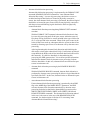
This product is designed and manufactured for use in standard applications such as office work,
personal devices and household appliances. This product is not intended for special uses (atomic
controls, aeronautic or space systems, mass transport vehicle operating controls, medical devices for
life support, or weapons firing controls) where particularly high reliability requirements exist,
where the pertinent levels of safety are not guaranteed, or where a failure or operational error could
threaten a life or cause a physical injury (hereafter referred to as "mission-critical" use). Customers
considering the use of these products for mission-critical applications must have safety-assurance
measures in place beforehand. Moreover, they are requested to consult our sales representative
before embarking on such specialized use.
First Edition February 2007
The contents of this manual may be revised without prior notice.
The contents of this manual shall not be disclosed in any way or reproduced in any media without
the express written permission of Fujitsu Limited.
All Rights Reserved, Copyright © FUJITSU LIMITED 2007
C141-C013
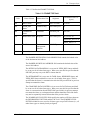
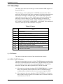
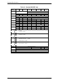
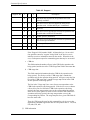
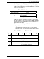
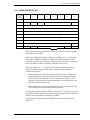
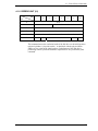
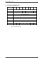
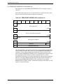
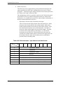
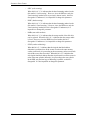
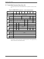
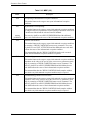
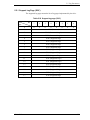
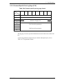
Revision History
(1/1)
Edition
Date
Revised section (*1)
(Added/Deleted/Altered)
Details
01
2007.02.28
—
—
*1 Section(s) with asterisk (*) refer to the previous edition when those were deleted.
C141-C013
This page is intentionally left blank.
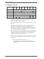
Preface
This manual explains concerning the hard disk drives with internal Serial Attached
SCSI (SAS) controller.
The purpose of this manual is to provide the specifications and functions of SAS
for use of these magnetic disk drives incorporated into user systems, and to present
the information necessary for creating host system software. This manual is written
for users who have a basic knowledge of hard disk drives and their use in computer
systems.
The composition of manuals related to these disk drives and the range of subjects
covered in this manual are shown in "Manual Organization," provided on a
subsequent page. Please use these other manuals along with this manual as
necessary.
The organization of this manual, related reference manual and conventions for alert
messages follow.
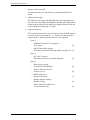
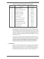
Overview of Manual
This manual consists of the following six chapters, glossary, abbreviation, and
index:
Chapter 1 SAS Interface
This chapter describes the topology, physical and electrical requirements, interface
protocol, and other operations of the interface.
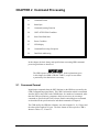
Chapter 2 Command Processing
This chapter describes the basic logical specifications related to command
processing.
Chapter 3 Data Buffer Management
This chapter describes the data buffer configuration, data transfer processing
functions and cache operations.
Chapter 4 Command Specifications
This chapter describes detailed command specifications and how to use them.
Chapter 5 Parameter Data Format
This chapter describes the parameter data formats provided by the disk drives and
how to use them.
C141-C013
1
Preface
Chapter 6 Sense Data and Error Recovery Methods
This chapter describes the configuration and contents of sense data which report to
the host system when an error occurs, etc., key information necessary for error
recovery, recommended procedures for error recovery to be executed through host
system software and retry processing.
Chapter 7 Disk Media Management
This chapter describes the procedure for initializing the disk media, methods of
treating media defects and data recovery methods.
Glossary
The glossary explains technical terms which are necessary to the reader's
understanding when reading this manual.
Acronyms and Abbreviations
This list shows the full spelling of abbreviations used in this manual.
Index
2
C141-C013
Preface
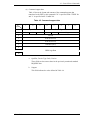
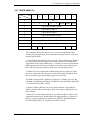
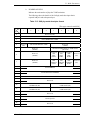
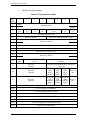
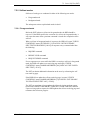
CONVENTIONS USED IN THIS MANUAL
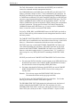
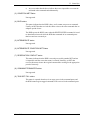
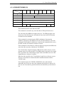
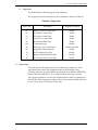
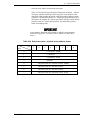
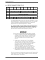
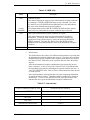
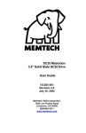
The model names of the disk drives covered by this manual differ depending
on their device types and capacity (*1). In addition, these disk drives are called
Hard Disk Drive (HDD), "drive" or "device" in this manual.
Note: Model Name
M BA 3 147 RC
Interface type
Formatted capacity [One gigabyte (GB) = one billion
bytes; accessible capacity will be less
and actual capacity depends on the
operating environment and
formatting.]
Disk size
3: 3.5 inch
2: 2.5 inch
Type
BA: 3.5-inch, 15,000rpm
BB: 2.5-inch, 10,025rpm
BC: 2.5-inch, 15,000rpm
Decimal numbers are represented normally.
Hexadecimal numbers are represented as shown in the following examples:
X'17B9', 17B9h, 17B9H, or 17B9H.
Binary number is represented as "010", 010b.
An X is used to represent mode parameters that are ignored by the MODE
SELECT and MODE SELECT EXTENDED commands. An X is also used
to represent mode parameters reported by the MODE SELECT and MODE
SELECT EXTENDED commands and that vary depending on conditions at
the time.
C141-C013
3
Preface
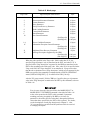
Conventions for Alert Messages
This manual uses the following conventions to show the alert messages. An alert
message consists of an alert signal and alert statements. The alert signal consists of
an alert symbol and a signal word or just a signal word.
The following are the alert signals and their meanings:
This indicates a hazardous situation likely to result in
serious personal injury if the user does not perform
the procedure correctly.
This indicates a hazardous situation could result in
serious personal injury if the user does not perform
the procedure correctly.
This indicates a hazardous situation could result in
minor or moderate personal injury if the user does
not perform the procedure correctly. This alert signal
also indicates that damages to the product or other
property, may occur if the user does not perform the
product correctly.
This indicates information that could help the user
use the product more efficiently.
In the text, the alert signal is centered, followed below by the indented message. A
wider line space precedes and follows the alert message to show where the alert
message begins and ends. The following is an example:
(Example)
It is possible to use bit 7 and bit 6 of the control byte as an inherent
control field in future product specifications. It is recommended that
the INIT specify zero in this field.
Attention
Please forward any comments you may have regarding this manual.
To make this manual easier for users to understand, opinions from readers are
needed. Please write your opinions or requests on the Comment at the back of this
manual and forward it to the address described in the sheet.
4
C141-C013
Preface
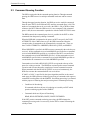
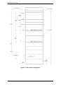
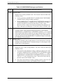
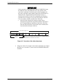
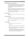
MANUAL ORGANIZATION
Product Maintenance
Manual
1.
2.
3.
4.
5.
6.
7.
General Description
Specifications
Data Format
Installation Requirements
Installation
Diagnostics and Maintenance
Error Analysis
Interface Specifications
(This Manual)
1.
2.
3.
4.
5.
6.
7.
Serial Attached SCSI (SAS) Interface
Command Processing
Data Buffer Management
Command Specifications
Parameter Data Formats
Sense Data and Error Recovery
Disk Media Management
C141-C013
5
Preface
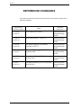
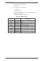
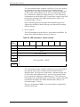
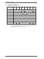
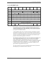
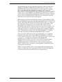
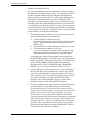
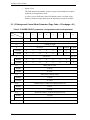
REFERENCED STANDARDS
The product specifications and functions described in this manual conform to the
following standards:
Specification
(document) number
6
Name
Concerned
organization
T10/1562-D
Revision 05
Serial Attached SCSI (SAS)
American national
Standards Institute
(ANSI)
T10/1601-D
Revision 10
Serial Attached SCSI-1.1 (SAS-1.1)
American national
Standards Institute
(ANSI)
T10/1236D
Revision 20
Information technology SCSI Primary
Commands-2 (SPC-2)
American national
Standards Institute
(ANSI)
T10/996D
Revision 8C
Information Technology SCSI-3 Block
Commands (SBC)
American national
Standards Institute
(ANSI)
T10/1157D
Revision 24
Information technology SCSI-3 Architecture
Model (SAM-2)
American national
Standards Institute
(ANSI)
T10/1561
Revision 14
Information technology SCSI-3 Architecture
Model (SAM-3)
American national
Standards Institute
(ANSI)
C141-C013
Contents
CHAPTER 1
SAS Interface .............................................................................21
1.1
Topologies in SAS Interface ....................................................................22
1.1.1
SAS Layering ........................................................................................23
1.1.2
Physical links and phys .........................................................................24
1.1.3
Ports (narrow ports and wide ports) ......................................................24
1.1.4
SAS devices...........................................................................................26
1.1.5
Pathways................................................................................................27
1.1.6
Connections ...........................................................................................28
1.2
Names and identifiers...............................................................................29
1.2.1
SAS addresses .......................................................................................29
1.2.2
Hashed SAS address..............................................................................30
1.3
Phy layer ..................................................................................................31
1.3.1
8b10b coding .........................................................................................31
1.3.2
Link reset sequence ...............................................................................32
1.3.3
Start conditions of the link reset sequence ............................................33
1.3.4
Out of band (OOB) signals....................................................................33
1.3.5
SAS OOB sequency ..............................................................................36
1.3.5.1 Exception handling in the OOB sequence.............................................38
1.3.6
SAS speed negotiation sequence ...........................................................38
1.3.6.1 Phy reset sequence after devices are attached .......................................42
1.3.6.2 When the speed negotiation sequence is successful ..............................43
1.3.6.3 Exception handling in the speed negotiation sequence .........................43
1.3.7
1.4
Phy layer dword synchronization (DWS)..............................................43
Link layer .................................................................................................44
1.4.1
Primitives...............................................................................................44
1.4.2
Primitive sequences ...............................................................................47
1.4.3
Primitives not specific to type of connections.......................................47
1.4.3.1 AIP (Arbitration in progress).................................................................47
1.4.3.2 ALIGN...................................................................................................47
C141-C013
7
Contents
1.4.3.3 BREAK................................................................................................. 48
1.4.3.4 BROADCAST ...................................................................................... 48
1.4.3.5 CLOSE.................................................................................................. 49
1.4.3.6 EOAF (End of address frame) .............................................................. 49
1.4.3.7 ERROR................................................................................................. 49
1.4.3.8 HARD_RESET..................................................................................... 49
1.4.3.9 NOTIFY................................................................................................ 50
1.4.3.10 OPEN_ACCEPT ................................................................................ 50
1.4.3.11 OPEN_REJECT ................................................................................. 50
1.4.3.12 SOAF (Start of address frame)........................................................... 53
1.4.4
Primitives used only inside SSP and SMP connections ....................... 54
1.4.4.1 ACK (acknowledge) ............................................................................. 54
1.4.4.2 CREDIT_BLOCKED ........................................................................... 54
1.4.4.3 DONE ................................................................................................... 54
1.4.4.4 EOF (End of frame) .............................................................................. 56
1.4.4.5 NAK (negative acknowledgement) ...................................................... 56
1.4.4.6 RRDY ................................................................................................... 56
1.4.4.7 SOF (Start of frame) ............................................................................. 56
1.4.5
Clock skew management ...................................................................... 57
1.4.6
Idle physical link .................................................................................. 57
1.4.7
Scrambling............................................................................................ 58
1.5
Address frames........................................................................................ 59
1.5.1
Address frames overview...................................................................... 59
1.5.2
IDENTIFY address frame..................................................................... 60
1.5.3
OPEN address frame............................................................................. 62
1.5.4
Identification and hard reset sequence.................................................. 65
1.5.5
Connections .......................................................................................... 66
1.5.5.1 Connections overview .......................................................................... 66
1.5.5.2 Connection request ............................................................................... 66
1.5.5.3 Connection responses ........................................................................... 67
1.5.5.4 Arbitration fairness ............................................................................... 67
1.5.5.5 Aborting a connection request .............................................................. 69
1.5.5.6 Closing a connection ............................................................................ 70
1.5.5.7 Breaking a connection .......................................................................... 71
1.5.5.8 Rate matching ....................................................................................... 71
8
C141-C013
Contents
1.5.6
SSP link layer ........................................................................................72
1.5.6.1 SSP frame transmission and reception ..................................................73
1.5.6.2 SSP flow control....................................................................................73
1.5.6.3 Interlocked frames .................................................................................73
1.5.6.4 Closing an SSP connection....................................................................76
1.6
Transport layer .........................................................................................78
1.6.1
SSP frame format ..................................................................................78
1.6.2
Information units ...................................................................................81
1.6.2.1 COMMAND information unit...............................................................81
1.6.2.2 TASK information unit..........................................................................84
1.6.2.3 XFER_RDY information unit ...............................................................86
1.6.2.4 DATA information unit.........................................................................89
1.6.2.5 RESPONSE information unit ................................................................92
CHAPTER 2
C141-C013
1.6.3
Sequences of SSP frames ......................................................................96
1.6.4
Exceptional event processing of a drive ................................................98
Command Processing .............................................................103
2.1
Command Format ..................................................................................103
2.2
Status Byte .............................................................................................108
2.3
Command Queuing Function .................................................................110
2.4
UNIT ATTENTION Condition .............................................................111
2.4.1
Generation of the UNIT ATTENTION condition ...............................111
2.4.2
Response and release condition at UNIT ATTENTION condition
hold state...............................................................................................112
2.4.3
UNIT ATTENTION condition multiple hold .....................................113
2.5
Sense Data Hold State............................................................................113
2.6
Power Condition ....................................................................................114
2.7
LED Display ..........................................................................................116
2.8
Command Processing Exceptions ..........................................................116
2.8.1
Overlapped tag ....................................................................................116
2.8.2
Illegal LUN specification ....................................................................117
9
Contents
2.8.3
Reserved operation code..................................................................... 118
2.8.4
Error recovery processing................................................................... 118
2.8.5
Abort processing................................................................................. 119
2.8.6
Fatal hardware errors .......................................................................... 122
2.9
CHAPTER 3
2.9.1
Definition of data space ...................................................................... 122
2.9.2
Logical block addressing .................................................................... 125
Data Buffer Management ........................................................ 127
3.1
3.1.1
3.2
CHAPTER 4
Data Block Addressing.......................................................................... 122
Data Buffer............................................................................................ 127
Data buffer configuration and basic operation ................................... 127
Look-Ahead Cache Feature................................................................... 130
3.2.1
Caching operation............................................................................... 130
3.2.2
Caching parameters ............................................................................ 133
3.2.3
Look-Ahead operation, Look-Ahead volume..................................... 133
Command Specifications........................................................ 135
4.1
Control/Sense Commands ..................................................................... 135
4.1.1
TEST UNIT READY (00).................................................................. 135
4.1.2
INQUIRY (12).................................................................................... 136
4.1.3
READ CAPACITY (25)..................................................................... 151
4.1.4
MODE SELECT (15) ......................................................................... 153
4.1.5
MODE SELECT EXTENDED (55) ................................................... 163
4.1.6
MODE SENSE (1A)........................................................................... 166
4.1.7
MODE SENSE EXTENDED (5A)..................................................... 174
4.1.8
REZERO UNIT (01)........................................................................... 177
4.1.9
START/STOP UNIT (1B).................................................................. 178
4.1.10 RESERVE (16)................................................................................... 180
4.1.11 RESERVE EXTENDED (56)............................................................. 182
4.1.12 RELEASE (17) ................................................................................... 183
4.1.13 RELEASE EXTENDED (57)............................................................. 184
4.1.14 REQUEST SENSE (03) ..................................................................... 185
4.1.15 LOG SELECT (4C) ............................................................................ 187
10
C141-C013
Contents
4.1.16 LOG SENSE (4D) ...............................................................................192
4.1.17 PERSISTENT RESERVE IN (5E)......................................................194
4.1.18 PERSISTENT RESERVE OUT (5F) ..................................................201
4.1.19 REPORT LUNS (A0)..........................................................................207
4.1.20 REPORT DEVICE IDENTIFIER (A3)...............................................209
4.1.21 SET DEVICE IDENTIFIER (A4).......................................................211
4.2
4.2.1
READ (08) ..........................................................................................213
4.2.2
READ EXTENDED (28) ....................................................................215
4.2.3
WRITE (0A)........................................................................................216
4.2.4
WRITE EXTENDED (2A)..................................................................218
4.2.5
WRITE AND VERIFY (2E) ...............................................................219
4.2.6
VERIFY (2F).......................................................................................220
4.2.7
SEEK (0B)...........................................................................................221
4.2.8
SEEK EXTENDED (2B) ....................................................................222
4.2.9
SYNCHRONIZE CACHE (35)...........................................................223
4.3
FORMAT UNIT (04) ..........................................................................224
4.3.2
REASSIGN BLOCKS (07) .................................................................235
4.3.3
READ DEFECT DATA (37) ..............................................................239
4.3.4
READ DEFECT DATA (B7)..............................................................244
Maintenance, Diagnostic Commands.....................................................246
4.4.1
SEND DIAGNOSTIC (1D).................................................................246
4.4.2
RECEIVE DIAGNOSTIC RESULTS (1C) ........................................258
4.4.3
WRITE BUFFER (3B) ........................................................................263
4.4.4
READ BUFFER (3C)..........................................................................270
4.4.5
READ LONG (3E) ..............................................................................275
4.4.6
WRITE LONG (3F) ............................................................................277
4.4.7
WRITE SAME (41).............................................................................279
Parameter Data Format ........................................................... 281
5.1
C141-C013
Format Commands .................................................................................224
4.3.1
4.4
CHAPTER 5
Data Access Commands.........................................................................213
Mode Parameters....................................................................................281
5.1.1
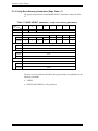
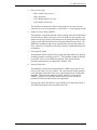
Read/Write Error Recovery Parameters (Page Code = 1) ...................282
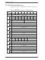
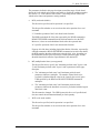
5.1.2
Disconnect/Reconnect Parameters (Page Code = 2) ...........................287
11
Contents
5.1.3
Format Parameters (Page Code = 3) ................................................... 289
5.1.4
Drive Parameters (Page Code = 4) ..................................................... 294
5.1.5
Verify Error Recovery Parameters (Page Code = 7) .......................... 296
5.1.6
Caching Parameters (Page Code = 8) ................................................. 298
5.1.7
Control Mode Parameters (Page Code = 0A) ..................................... 304
5.1.8
Notch Parameters (Page Code = 0C) .................................................. 308
5.1.9
Port Control Parameter (Page Code = 19) .......................................... 310
5.1.10 Power Condition Parameter (Page Code = 1A) .................................. 316
5.1.11 Informational Exceptions Control Page (Page Code = 1C) ................ 317
5.1.12 Background Control Mode Parameter (Page Code =
1C/subpage = 01)................................................................................ 322
5.1.13 Additional Error Recovery Parameters (Page Code = 21).................. 325
5.2
Log Parameters...................................................................................... 327
5.2.1
Support Log Page (X'00') ................................................................... 329
5.2.2
Buffer Overrun/Underrun Page (X'01') .............................................. 330
5.2.3
Write Error Count Page (X'02') .......................................................... 331
5.2.4
Read Error Count Page (X'03') ........................................................... 335
5.2.5
Verify Error Count Page (X'05') ......................................................... 338
5.2.6
Non-Medium Error Count Page (X'06').............................................. 342
5.2.7
Temperature Page (X'0D') .................................................................. 342
5.2.8
Start-Stop Cycle Counter Page (X'0E')............................................... 344
5.2.9
Application Client Page (X'0F').......................................................... 347
5.2.10 Self-Test Result Page (X'10').............................................................. 348
5.2.11 Background Medium Scan Page (X'15')............................................. 350
5.2.12 Protocol Specific Port Log Page (X'18')............................................. 353
5.2.13 SMART Status Page (X'2F')............................................................... 357
5.2.14 SMART Data Page (X'38') ................................................................. 357
CHAPTER 6
Sense Data and Error Recovery Methods ............................. 359
6.1
6.1.1
Sense data format................................................................................ 359
6.1.2
Sense data basic information .............................................................. 361
6.1.3
Sense data additional information ...................................................... 371
6.2
12
Sense Data ............................................................................................ 359
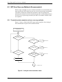
INIT Error Recovery Methods (Recommended).................................. 372
C141-C013
Contents
6.2.1
Termination status analysis and error recovery methods ....................372
6.2.2
Sense data analysis and error recovery methods .................................374
6.2.3
Error logging .......................................................................................382
6.3
CHAPTER 7
Disk Drive Error Recovery Processing .................................................382
6.3.1
Error states and retry processing procedures.......................................382
6.3.2
Auto alternate block allocation processing..........................................384
6.3.3
Error recovery processing control .......................................................386
Disk Media Management ......................................................... 389
7.1
Defect Management ...............................................................................389
7.2
Disk Media Initialization .......................................................................392
7.2.1
Initialization during installation ..........................................................392
7.2.2
Re-initialization ...................................................................................393
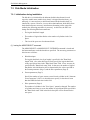
7.3
Alternate Block Allocation Processing ..................................................395
7.4
Background Media Scan (BMS) ............................................................396
7.4.1
Overview .............................................................................................396
7.4.2
Background Media Scan......................................................................396
7.4.2.1 Background Media Scan (BMS) mode................................................396
7.4.2.2 Pre-Scan mode.....................................................................................396
7.4.2.3 Write command operation during a Pre-Scan......................................397
7.4.2.4 Conditions for operation......................................................................397
7.4.3
Mode Page...........................................................................................398
7.4.4
Background Media Scan Log Page .....................................................400
7.5
Drive Self-Test (DST)...........................................................................404
7.5.1
Overview .............................................................................................404
7.5.2
Self-test modes ....................................................................................405
7.5.2.1 Foreground mode ................................................................................405
7.5.2.2 Background mode................................................................................406
C141-C013
7.5.3
Matters that are common to both modes .............................................407
7.5.4
Short self-test.......................................................................................407
7.5.5
Extended self-test ................................................................................407
7.5.6
Test segments ......................................................................................407
13
Contents
7.6
SMART (Self-Monitoring Analysis and Reporting Technology)......... 410
7.6.1
Overview ............................................................................................ 410
7.6.2
Data analysis....................................................................................... 411
7.6.3
Failure prediction method................................................................... 412
7.6.4
Reporting function .............................................................................. 416
Glossary ............................................................................................................ 417
Acronyms and Abbreviations .......................................................................... 419
Index ................................................................................................................. 421
14
C141-C013
Contents
Illustrations
Figures
Figure 1.1 SAS drive connection patterns ............................................................. 22
Figure 1.2 SAS control layers................................................................................ 23
Figure 1.3 Physical links and phys ........................................................................ 24
Figure 1.4 Ports (narrow ports and wide ports) ..................................................... 25
Figure 1.5 SAS devices ......................................................................................... 26
Figure 1.6 Example of potential pathways ............................................................ 27
Figure 1.7 Reset-related terminology .................................................................... 32
Figure 1.8 OOB signal transmission...................................................................... 34
Figure 1.9 OOB signal detection ........................................................................... 36
Figure 1.10 SAS to SAS OOB sequence ................................................................. 37
Figure 1.11 SAS speed negotiation window............................................................ 39
Figure 1.12 SAS speed negotiation sequence (Example 1) ..................................... 41
Figure 1.13 SAS speed negotiation sequence (Example 2) ..................................... 41
Figure 1.14 Phy reset sequence (Example).............................................................. 42
Figure 1.15 Connection request timeout example ................................................... 69
Figure 1.16 Closing a connection example.............................................................. 70
Figure 1.17 Interlocked frames................................................................................ 75
Figure 1.18 Non-interlocked frames with the same tag........................................... 76
Figure 1.19 Non-interlocked frames with different tags.......................................... 76
Figure 1.20 Closing an SSP connection example.................................................... 77
Figure 1.21 Example of XFER_RDY frames.......................................................... 88
Figure 1.22 Example of TASK frame...................................................................... 96
Figure 1.23 Example of write command ................................................................. 97
Figure 1.24 Example of read command................................................................... 97
Figure 1.25 Example of the processing sequence for an exceptional event ............ 99
Figure 2.1 Data space configuration.................................................................... 124
Figure 3.1 Data buffer configuration (in the case of 8 cache segments) ............. 128
Figure 4.1 MODE SELECT parameter structure................................................. 155
Figure 4.2 Correction of the defect descriptor..................................................... 238
Figure 6.1 Analysis of the termination status ...................................................... 372
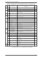
Tables
Table 1.1
Table 1.2
Table 1.3
Table 1.4
C141-C013
SAS address format.............................................................................. 29
Hashed SAS address code parameter ................................................... 30
Usage of special characters .................................................................. 31
OOB signal timing specifications ........................................................ 33
15
Contents
Table 1.5
Table 1.6
Table 1.7
Table 1.8
Table 1.9
Table 1.10
Table 1.11
Table 1.12
Table 1.13
Table 1.14
Table 1.15
Table 1.16
Table 1.17
Table 1.18
Table 1.19
Table 1.20
Table 1.21
Table 1.22
Table 1.23
Table 1.24
Table 1.25
Table 1.26
Table 1.27
Table 1.28
Table 1.29
Table 1.30
Table 1.31
Table 1.32
Table 1.33
Table 1.34
Table 1.35
Table 1.36
Table 1.37
Table 1.38
Table 1.39
Table 1.40
Table 1.41
Table 1.42
Table 1.43
Table 1.44
Table 1.45
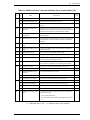
Table 2.1
Table 2.2
Table 2.3
16
OOB signal transmitter requirements ................................................... 34
OOB signal receiver burst time detection requirements....................... 35
OOB signal receiver idle time detection requirements......................... 35
OOB signal receiver negation time detection requirements ................. 35
SAS speed negotiation sequence timing specifications........................ 39
Primitives not specific to type of connection ....................................... 44
Primitives used only inside SSP and SMP connections ....................... 46
Primitive sequences .............................................................................. 47
OPEN_REJECT abandon primitives.................................................... 51
OPEN_REJECT retry primitives.......................................................... 52
DONE primitives.................................................................................. 55
Clock skew management ALIGN insertion requirement ..................... 57
Scrambling for different data dword types ........................................... 58
Address frame format ........................................................................... 59
IDENTIFY address frame format......................................................... 60
DEVICE TYPE field ............................................................................ 60
OPEN address frame format................................................................. 62
PROTOCOL field................................................................................. 62
CONNECTION RATE field ................................................................ 63
ARBITRATION WAIT TIME field..................................................... 64
Connection responses ........................................................................... 67
Arbitration priority for OPEN address frames passing on a
physical link ......................................................................................... 68
Abort connection responses.................................................................. 69
Close connection responses.................................................................. 70
Break connection responses ................................................................. 71
Rate matching ALIGN and/or NOTIFY insertion requirements .......... 72
SSP frame interlock requirements ........................................................ 74
SSP frame format ................................................................................. 78
FRAME TYPE field ............................................................................. 79
COMMAND information unit.............................................................. 81
TASK ATTRIBUTE field .................................................................... 82
TASK information unit......................................................................... 84
TASK MANAGEMENT FUNCTION field ........................................ 85
XFER_RDY information unit .............................................................. 86
An example of requested offset ............................................................ 88
DATA information unit........................................................................ 89
RESPONSE information unit ............................................................... 92
DATAPRES field ................................................................................. 92
RESPONSE DATA field...................................................................... 94
RESPONSE CODE field...................................................................... 94
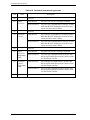
Exceptional event processing of a drive ............................................. 100
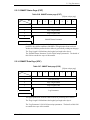
6-Byte CDB basic format ................................................................... 104
10-Byte CDB basic format ................................................................. 104
12-Byte CDB basic format ................................................................. 105
C141-C013
Contents
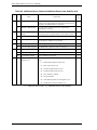
Table 2.4
Table 2.5
Table 2.6
Table 2.7
Table 2.8
Table 2.9
Table 2.10
Table 4.1
Table 4.2
Table 4.3
Table 4.4
Table 4.5
Table 4.6
Table 4.7
Table 4.8
Table 4.9
Table 4.10
Table 4.11
Table 4.12
Table 4.13
Table 4.14
Table 4.15
Table 4.16
Table 4.17
Table 4.18
Table 4.19
Table 4.20
Table 4.21
Table 4.22
Table 4.23
Table 4.24
Table 4.25
Table 4.26
Table 4.27
Table 4.28
Table 4.29
Table 4.30
Table 4.31
Table 4.32
Table 4.33
Table 4.34
Table 4.35
C141-C013
Operation code ................................................................................... 105
Control byte........................................................................................ 107
Status .................................................................................................. 108
LED display ....................................................................................... 116
Outline of disk drive error recovery processing................................. 118
Comparison between SAS and SCSI about definition ....................... 119
Reset processing during write ............................................................ 121
Standard INQUIRY data .................................................................... 138
VERSION field .................................................................................. 139
Command queuing ............................................................................. 141
Version descriptor .............................................................................. 142
Command support data....................................................................... 143
Support ............................................................................................... 144
VPD information ................................................................................ 145
VPD information: VPD identifier list ............................................... 145
VPD information: device serial No ................................................... 146
VPD information: device unique information.................................... 147
READ CAPACITY data .................................................................... 152
MODE SELECT command (Group 0) parameter configuration ....... 157
MODE SELECT parameters .............................................................. 161
MODE SELECT EXTENDED command (group 2) parameter
configuration ...................................................................................... 164
Mode page.......................................................................................... 167
MODE SENSE data type specifications ............................................ 168
MODE SENSE command (group 0) parameter configuration........... 170
MODE SENSE EXTENDED command (group 2) parameter
configuration ...................................................................................... 175
PC (page control) ............................................................................... 188
LOG SELECT command parameter configuration............................ 188
Page code ........................................................................................... 189
Log parameter .................................................................................... 190
"Page Code" assignment for the log pages......................................... 193
PERSISTENT RESERVE IN service actions .................................... 195
PERSISTENT RESERVE IN parameter data for READ KEYS ....... 196
PERSISTENT RESERVE IN parameter data for READ
RESERVATIONS.............................................................................. 197
Format of reservation descriptors....................................................... 198
Persistent reservations scope.............................................................. 199
Persistent reservations type codes ...................................................... 200
PERSISTENT RESERVE OUT service action codes........................ 203
PERSISTENT RESERVE OUT parameter list.................................. 204
PERSISTENT RESERVE OUT service action and valid
parameters .......................................................................................... 206
REPORT LUNS parameter data......................................................... 208
REPORT DEVICE IDENTIFIER parameter data ............................. 210
SET DEVICE IDENTIFIER parameter data...................................... 212
17
Contents
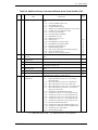
Table 4.36
Table 4.37
Table 4.38
Table 4.39
Table 4.40
Table 4.41
Table 4.42
Table 4.43
Table 4.44
Table 4.45
Table 4.46
Table 4.47
Table 4.48
Table 4.49
Table 4.50
Table 4.51
Table 4.52
Table 4.53
Table 4.54
Table 4.55
Table 4.56
Table 4.57
Table 4.58
Table 4.59
Table 4.60
Table 4.61
Table 4.62
Table 4.63
Table 4.64
Table 4.65
Table 5.1
Table 5.2
Table 5.3
Table 5.4
Table 5.5
Table 5.6
Table 5.7
Table 5.8
Table 5.9
18
Defect list format................................................................................ 226
FORMAT UNIT command parameter list configuration ................... 227
Defect descriptor: byte distance from index format .......................... 230
Defect descriptor: physical sector address format ............................. 231
FORMAT UNIT command defect processing ................................... 233
REASSIGN BLOCK command: defect data list configuration......... 236
Defect data type.................................................................................. 239
Defect data format .............................................................................. 240
READ DEFECT DATA command: defect data configuration ......... 240
Defect data conditions ........................................................................ 242
READ DEFECT DATA command (B7): defect data
configuration ...................................................................................... 245
Self-diagnosis test............................................................................... 247
Error recovery control flags during the self-diagnosis test................. 248
SEND DIAGNOSTIC command: parameter list configuration ........ 250
Page code............................................................................................ 250
SEND DIAGNOSTIC parameters: page code list............................. 251
SEND DIAGNOSTIC parameters: PHY Test function..................... 252
SEND DIAGNOSTIC parameters: logical/physical address
conversion .......................................................................................... 255
Specifying address format .................................................................. 255
SELF-TEST........................................................................................ 257
RECEIVE DIAGNOSTIC RESULTS command: response data
configuration ...................................................................................... 259
RECEIVE DIAGNOSTIC RESULTS response data: page
code list............................................................................................... 260
RECEIVE DIAGNOSTIC RESULTS response data:
logical/physical address conversion ................................................... 261
Address format ................................................................................... 262
WRITE BUFFER transfer mode ........................................................ 264
WRITE BUFFER command: buffer data (mode = 000, 001) ........... 265
READ BUFFER transfer mode .......................................................... 270
READ BUFFER command: buffer data (mode = 0000, 0001) ......... 271
READ BUFFER command: buffer descriptor.................................... 273
READ BUFFER command: echo buffer descriptor .......................... 274
MODE SELECT parameters: read/write error recovery
parameters........................................................................................... 282
Combinations of error recovery flags................................................. 286
MODE SELECT parameters: disconnect/reconnect parameters ........ 287
MODE SELECT parameters: format parameters .............................. 289
Details of parameters on MODE SELECT parameter: pages 3,
4, and C............................................................................................... 293
MODE SELECT parameters: drive parameters ................................ 294
MODE SELECT parameters: verify error recovery parameters ....... 296
MODE SELECT parameters: caching parameters ............................ 298
MODE SELECT parameters: control mode parameters.................... 304
C141-C013
Contents
Table 5.10
Table 5.11
Table 5.12
Table 5.13
Table 5.14
Table 5.15
Table 5.16
Table 5.17
Table 5.18
Table 5.19
Table 5.20
Table 5.21
Table 5.22
Table 5.23
Table 5.24
Table 5.25
Table 5.26
Table 5.27
Table 5.28
Table 5.29
Table 5.30
Table 5.31
Table 5.32
Table 5.33
Table 5.34
Table 5.35
Table 5.36
Table 5.37
Table 5.38
Table 5.39
Table 5.40
Table 5.41
Table 5.42
Table 5.43
C141-C013
MODE SELECT parameters: notch parameters................................ 308
Port control parameter: Page 0 Format (Short Page Format) ............. 311
Port control parameter: Sub Page Format (Long Format).................. 312
SAS phy mode descriptor format ....................................................... 313
Power condition parameter: Page 0 Format (Short Page
Format)............................................................................................... 316
MODE SELECT parameters: informational exception control
page .................................................................................................... 317
MRIE.................................................................................................. 320
Interval timer ...................................................................................... 321
MODE SELECT parameters: background control mode
parameter............................................................................................ 322
MODE SELECT parameters: additional error recovery
parameters .......................................................................................... 325
Mode parameter default values .......................................................... 326
Log parameter format......................................................................... 327
Support log page (X'00') .................................................................... 329
Buffer overrun/underrun page (X'01') ................................................ 330
Write error count page (X'02')............................................................ 331
Write errors recovered without delays (page 02, code 0000)............ 332
Write errors recovered with possible delays (page 02, code
0001) .................................................................................................. 332
Total write errors posted (page 02, code 0002).................................. 333
Total recoverable write errors posted to INIT (page 02, code
0003) .................................................................................................. 333
Total write bytes processed (page 02, code 0005) ............................. 334
Total unrecoverable write errors posted to INIT (page 02, code
0006) .................................................................................................. 334
Read error count page (X'03') ............................................................ 335
Read errors recovered without delays (page 03, code 0000) ............. 335
Read errors recovered with possible delays (page 03, code
0001) .................................................................................................. 336
Total read errors posted (page 03, code 0002) ................................... 336
Total recoverable read errors posted to INIT (page 03, code
0003) .................................................................................................. 337
Total read bytes processed (page 03, code 0005)............................... 337
Total unrecoverable read errors posted to INIT (page 03, code
0006) .................................................................................................. 338
Verify error count page (X'05') .......................................................... 338
Verify errors recovered without delays (page 05, code 0000) ........... 339
Verify errors recovered with possible delays (page 05, code
0001) .................................................................................................. 339
Total verify errors posted (page 05, code 0002) ................................ 340
Total recoverable verify errors posted to INIT (page 05, code
0003) .................................................................................................. 340
Total verify bytes processed (page 05, code 0005)............................ 341
19
Contents
Table 5.44 Total unrecoverable verify errors posted to INIT (page 05,
code 0006) .......................................................................................... 341
Table 5.45 Non-medium error count page (X'06')................................................ 342
Table 5.46 Temperature page (X'0D') .................................................................. 342
Table 5.47 Temperature (page 0D, code 0000) .................................................... 343
Table 5.48 Reference temperature (page 0D, code 0001) .................................... 343
Table 5.49 Start-stop cycle counter page (X'0E') ................................................. 344
Table 5.50 Date of manufacture (page 0E, code 0001) ........................................ 344
Table 5.51 Accounting date (page 0E, code 0002)............................................... 345
Table 5.52 Specified cycle count over device lifetime (page 0E, code
0003)................................................................................................... 345
Table 5.53 Start-stop cycle counter (page 0E, code 0004) ................................... 346
Table 5.54 Application client page (X'0F')........................................................... 347
Table 5.55 General usage application client parameter data (page 0F, code
0000-003F) ......................................................................................... 347
Table 5.56 Self-test result page (X'10') ................................................................ 348
Table 5.57 Self-test result parameter data (page 10, code 0001-0014) ................ 348
Table 5.58 Self-test results values ........................................................................ 349
Table 5.59 Background medium scan page (X'15') .............................................. 350
Table 5.60 Background medium scan status parameter ....................................... 350
Table 5.61 BMS status ......................................................................................... 351
Table 5.62 Background medium scan parameter ................................................. 352
Table 5.63 Reassign status ................................................................................... 352
Table 5.64 Protocol specific port log page format ............................................... 353
Table 5.65 Log parameter format ......................................................................... 354
Table 5.66 SMART status page (X'2F') ............................................................... 357
Table 5.67 SMART data page (X'38') .................................................................. 357
Table 6.1 Sense data format ............................................................................... 360
Table 6.2 Sense key inherent information .......................................................... 363
Table 6.3 Sense key............................................................................................ 364
Table 6.4 Additional Sense Code and Additional Sense Code Qualifier ........... 365
Table 6.5 Sense data error classification ............................................................ 375
Table 6.6 Error recovery processing procedures ................................................ 378
Table 6.7 Disk drive errors and number of retries.............................................. 387
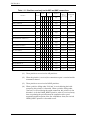
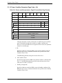
Table 7.1 Mode Page 0x1C SubPage 0x01 (Background Control Mode
Page)................................................................................................... 398
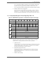
Table 7.2 Background Media Scan Log Page format......................................... 400
Table 7.3 BMS Status parameter format ............................................................ 401
Table 7.4 Medium Scan parameter format ......................................................... 402
Table 7.5 SMART ASC/ASCQ.......................................................................... 412
Table 7.6 SMART thresholds............................................................................. 415
20
C141-C013
CHAPTER 1 SAS Interface
1.1
Topologies in SAS Interface
1.2
Names and identifiers
1.3
Phy layer
1.4
Link layer
1.5
Address frames
1.6
Transport layer
This chapter describes the topology, interface protocol, and operation of the SAS
interface.
C141-C013
21
SAS Interface
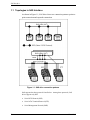
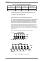
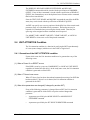
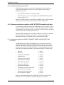
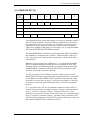
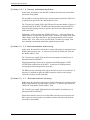
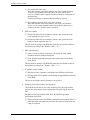
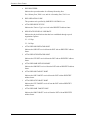
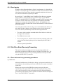
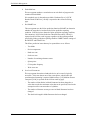
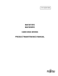
1.1 Topologies in SAS Interface
As shown in Figure 1.1, SAS drives have two connection patterns: point-topoint connection and expander connection.
Figure 1.1 SAS drive connection patterns
SAS supports the three protocols listed below. Among these protocols, SAS
drives support only SSP.
22
•
Serial SCSI Protocol (SSP)
•
Serial ATA Tunneled Protocol (STP)
•
Serial Management Protocol (SMP)
C141-C013
1.1 Topologies in SAS Interface
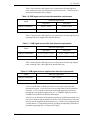
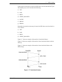
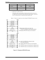
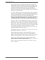
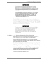
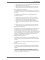
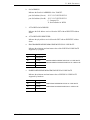
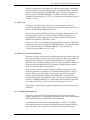
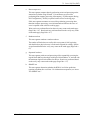
1.1.1 SAS Layering
As shown in Figure 1.2, for SAS, the following six control layers are defined:
•
Physical layer:
•
Phy (transceiver) layer: 8B/10B code, OOB, and speed negotiation
•
Link layer:
Primitives, address frames, and connection control
•
Port layer:
Wide port control
•
Transport layer:
Frame control
•
Application layer:
SCSI commands, mode pages, and log pages
Electric properties related to cables, connectors,
and signals
Application layer
Transport layer
Port layer
Link layer
Phy layer
Physical layer
Figure 1.2 SAS control layers
C141-C013
23
SAS Interface
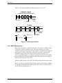
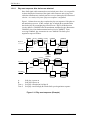
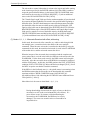
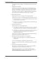
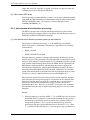
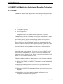
1.1.2 Physical links and phys
A physical link is a set of four wires used as two differential signal pairs. One
differential signal transmits in one direction while the other differential signal
transmits in the opposite direction. Data may be transmitted in both directions
simultaneously.
A physical phy contains a transceiver which electrically interfaces to a physical
link, which attaches to another physical phy.
Phys are contained in ports. Phys interface to the service delivery subsystem.
Figure 1.3 shows two phys attached with a physical link.
An attached phy is the phy to which a phy is attached over a physical link. A
device may contain one or more phys. Each phy has a phy identifier which is
unique within the device.
Figure 1.3 Physical links and phys
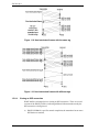
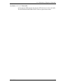
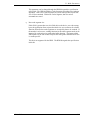
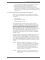
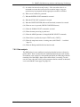
1.1.3 Ports (narrow ports and wide ports)
A port contains one or more phys. Ports in a device are associated with physical
phys based on the identification sequence. A port is created from a set of physical
phys if one or more physical phys contained within a device:
a)
transmit the same SAS address during the identification sequence; and
b) receive the same SAS address during the identification sequence (i.e., the
corresponding attached phy or phys transmit the same SAS address).
24
C141-C013
1.1 Topologies in SAS Interface
A wide port is created if there is more than one phy in the port. A narrow port is a
port with only one phy.
A wide link is the set of physical links that attach a wide port to another wide
port. A narrow link is the physical link that attaches a narrow port to another
narrow port.
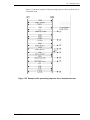
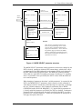
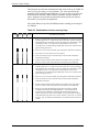
Figure 1.4 shows examples of narrow ports and wide ports, with a representation
of the SAS address transmitted during the identification sequence. Although
several phys on the left transmit SAS addresses of B, only phys attached to the
same SAS addresses become part of the same ports. The set of phys with SAS
address B attached to the set of phys with SAS address D become one port, while
the set of phys with SAS address B attached to the set of phys with SAS address E
become another port.
Figure 1.4 Ports (narrow ports and wide ports)
C141-C013
25
SAS Interface
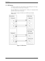
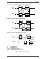
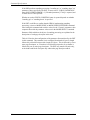
1.1.4 SAS devices
A SAS device contains one or more SAS ports, each containing one or more phys
(i.e., a SAS port may be a narrow port or a wide port).
Each single HDD unit is a separate SAS device. Usually, it is a single port or dual
port device, but does not use a wide port.
Figure 1.5 shows examples of SAS devices with different port and phy
configurations.
Figure 1.5 SAS devices
26
C141-C013
1.1 Topologies in SAS Interface
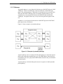
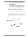
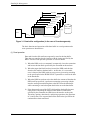
1.1.5 Pathways
A potential pathway is a set of physical links between a SAS INIT phy and a SAS
TARG phy. When a SAS INIT phy is directly attached to a SAS TARG phy,
there is one potential pathway. When there are expander devices between a SAS
INIT phy and a SAS TARG phy, there are multiple potential pathways, each
consisting of a set of physical links between the SAS INIT phy and the SAS
TARG phy. The physical links may or may not be using the same physical link
rate.
A pathway is a set of physical links between a SAS INIT phy and a SAS TARG
phy being used by a connection.
Figure 1.6 shows examples of potential pathways.
Figure 1.6 Example of potential pathways
A partial pathway is the set of physical links participating in a connection request
that has not reached the destination phy (e.g., the OPEN address frame has been
transmitted by the source phy but the OPEN address frame has not yet reached the
destination phy).
A partial pathway is blocked when path resources it requires are held by another
partial pathway.
C141-C013
27
SAS Interface
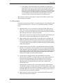
1.1.6 Connections
A connection is a temporary association between a SAS INIT port and a SAS
TARG port. During a connection all dwords from the SAS INIT port are
forwarded to the SAS TARG port, and all dwords from the SAS TARG port are
forwarded to the SAS INIT port.
A connection is pending when an OPEN address frame has been delivered along a
completed pathway to the destination phy but the destination phy has not yet
responded to the connection request. A connection is established when an
OPEN_ACCEPT is returned to the source phy.
A connection enables communication for one protocol: SSP, STP, or SMP. For
SSP and STP, connections may be opened and closed multiple times during the
processing of a command.
The connection rate is the effective rate of dwords through the pathway between a
SAS INIT phy and a SAS TARG phy, established through the connection request.
Every phy shall support a 1,5 Gbps connection rate regardless of its physical link
rate.
One connection may be active on a physical link at a time. If the connection is an
SSP or SMP connection and there are no dwords to transmit associated with that
connection, idle dwords are transmitted.
The number of connections established by a SAS port shall not exceed the number
of SAS phys within the SAS port (i.e., only one connection per SAS phy is
allowed). There shall be a separate connection on each physical link.
If multiple potential pathways exist between the SAS INIT port(s) and the SAS
TARG port(s), multiple connections may be established by a SAS port between
the following:
a)
one SAS INIT port to multiple SAS TARG ports;
b) one SAS TARG port to multiple SAS INIT ports; or
c)
one SAS INIT port to one SAS TARG port.
Once a connection is established, the pathway used for that connection shall not
be changed (i.e., all the physical links that make up the pathway remain dedicated
to the connection until it is closed).
28
C141-C013
1.2 Names and identifiers
1.2 Names and identifiers
Device names are worldwide unique names for devices within a transport
protocol. Port names are worldwide unique names for ports within a transport
protocol. Port identifiers are the values by which ports are identified within a
domain, and are used as SAS addresses. Phy identifiers are unique within a
device.
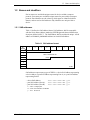
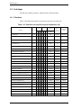
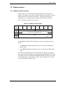
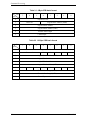
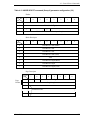
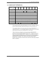
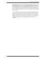
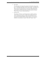
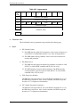
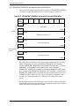
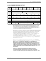
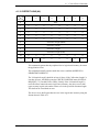
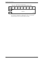
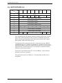
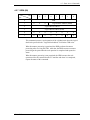
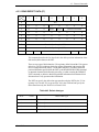
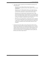
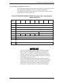
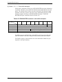
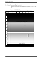
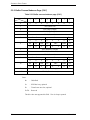
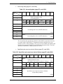
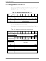
1.2.1 SAS addresses
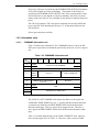
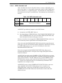
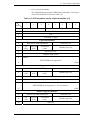
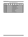
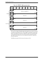
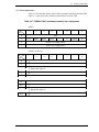
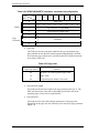
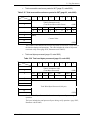
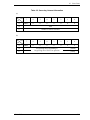
Table 1.1 defines the SAS address format. SAS addresses shall be compatible
with the NAA (Name Address Authority) IEEE Registered format identification
descriptor defined in SPC-3. The SAS address shall be worldwide unique. A SAS
address of 00000000_00000000h indicates an invalid SAS address.
Table 1.1 SAS address format
Bit
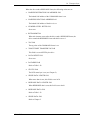
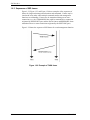
Byte
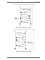
0
1
2
3
4
5
6
7
7
6
5
4
3
NAA (5h)
2
1
0
(MSB)
IEEE COMPANY ID
(LSB)
(MSB)
(LSB)
SAS addresses represent any types of WWNs: a device SAS address representing
a device address, a port SAS address representing Port-A, or a port SAS address
representing Port-B.
− device SAS address:
− port SAS address (Port-A):
− port SAS address (Port-B):
5CCC CCCX XXXX XXX yy00
5CCC CCCX XXXX XXX yy10
5CCC CCCX XXXX XXX yy11
C = 4 bits: Company ID
X = 4 bits: Serial number for WWN
y = 1 bit: Reserved
C141-C013
29
SAS Interface
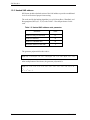
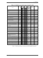
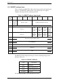
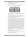
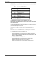
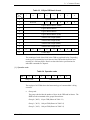
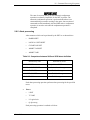
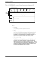
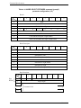
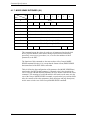
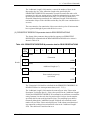
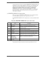
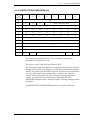
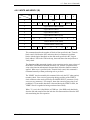
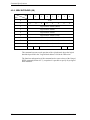
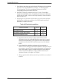
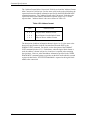
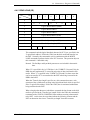
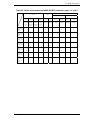
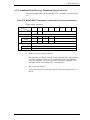
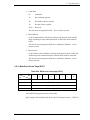
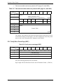
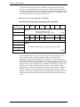
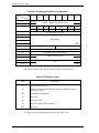
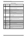
1.2.2 Hashed SAS address
SSP frames include a hashed version of the SAS address to provide an additional
level of verification of proper frame routing.
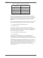
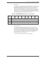
The code used for the hashing algorithm is a cyclic binary Bose, Chaudhuri, and
Hocquenghem (BCH) (63, 39, 9) codes. Table 1.2 lists the parameters for the
code.
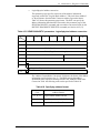
Table 1.2 Hashed SAS address code parameter
Parameter
Value
Number of bits per codeword
63
Number of data bits
39
Number of redundant bits
24
Minimum distance of the code
9
The generator polynomial for this code is:
G(x) = (x 6 + x + 1) (x 6 + x 4 + x 2 + x + 1) (x 6 + x 5 + x 2 + x + 1) (x 6 + x 3 + 1)
After multiplication of the factors, the generator polynomial is:
G(x) = x 24 + x 23 + x 22 + x 20 + x 19 + x 17 + x 16 + x 13 + x 10 + x 9 + x 8 + x 6 + x 5
+
x4+ x2+x+1
30
C141-C013
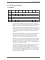
1.3 Phy layer
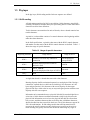
1.3 Phy layer
In the phy layer, 8b10b coding and the link reset sequence are defined.
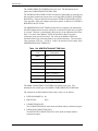
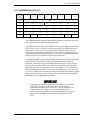
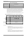
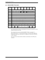
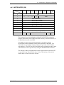
1.3.1 8b10b coding
All information transferred in SAS is encoded into 10-bit characters using 8b10b
encoding. Information includes data bytes representing data in a frame and control
characters used for frame delimiters.
Ten-bit characters are transferred in units of dwords, where a dword contains four
ten-bit characters.
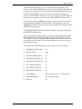
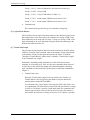
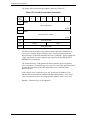
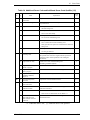
A primitive is a dword that consists of a control character at the beginning and the
other three data characters.
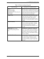
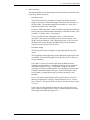
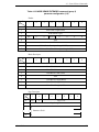
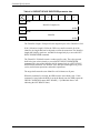
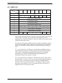
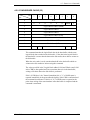
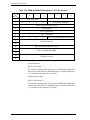
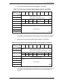
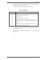
In the SAS specifications, a primitive that starts with the K28.5 control character
and another one that starts with the K28.6 control character are defined. Table 1.3
shows the usage of special characters.
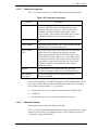
Table 1.3 Usage of special characters
Beginning character
Usage in SAS
Usage in SATA
K28.3
Primitive to be used only within STP
connection
All the primitives
except ALIGN
K28.5
ALIGN and most primitives that are
defined in SAS
ALIGN
K28.6
SATA_ERROR
(used on the physical link layer of SATA)
Not used.
Dxx.y
Data
Data
A single data dword is a dword that starts with a data character.
Running disparity shall be maintained separately on each physical link. During a
connection, expander devices shall convert incoming 10-bit characters to 8-bit
bytes and generate the 10-bit character with correct disparity for the output
physical link. Phys within a device may or may not begin operation with the same
disparity after the reset sequence.
Information to be transmitted across a physical link shall be encoded eight bits at
a time into a 10-bit character and then transmitted serially bit-by-bit across the
physical link. Information received over the physical link shall be collected ten
bits at a time, and those characters that are used for data, called data characters,
shall be decoded into the correct 8-bit data bytes. The 10-bit characters support all
256 8-bit combinations. 8b10b coding ensures that sufficient transitions are
present in the serial bit stream to make clock recovery possible at the receiver.
Such encoding also greatly increases the likelihood of detecting any single or
C141-C013
31
SAS Interface
multiple bit errors that may occur during transmission and reception of
information. In addition, some of the control characters of the transmission code
contain a distinct and easily recognizable bit pattern called a comma pattern
which assists a receiver in achieving character and dword alignment on the
incoming bit stream.
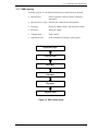
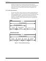
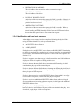
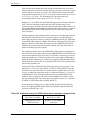
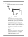
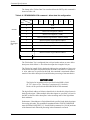
1.3.2 Link reset sequence
The link reset sequence consists of the phy reset sequence and the identification
sequence. The phy reset sequence consists of the out of band (OOB) sequence
and speed negotiation sequence. The hard reset sequence is performed only when
the HARD_RESET primitive is detected after the completion of the speed
negotiation. The HARD_RESET primitive detected at any time later than the
identification sequence is invalid. The hard reset sequence corresponds to the
reset condition of pSCSI.
Figure 1.7 Reset-related terminology
32
C141-C013
1.3 Phy layer
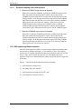
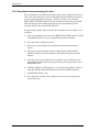
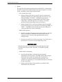
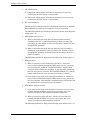
1.3.3 Start conditions of the link reset sequence
Drives start the link reset sequence when they detect any of the following
conditions:
•
The power is turned on.
•
A loss of signal is detected (OOB from the INIT).
•
A loss of sync is detected.
•
A HARD_RESET primitive is received during the link reset sequence.
•
A hot-plug timeout (500 ms) is detected during the link reset sequence.
•
The IDENTIFY address frame could not be received.
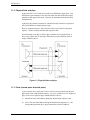
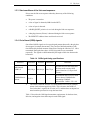
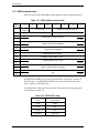
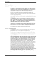
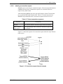
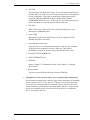
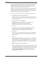
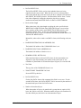
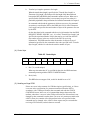
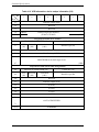
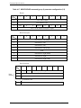
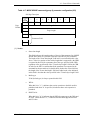
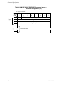
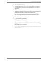
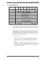
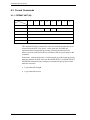
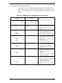
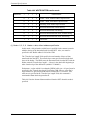
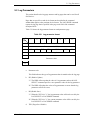
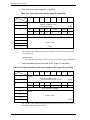
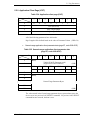
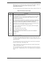
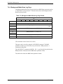
1.3.4 Out of band (OOB) signals
Out of band (OOB) signals are low-speed signal patterns detected by the phy that
do not appear in normal data streams. They consist of defined amounts of idle
time followed by defined amounts of burst time. During the idle time, D.C. idle is
transmitted. During the burst time, ALIGN (0) primitives are transmitted
repeatedly. The signals are differentiated by the length of idle time between the
burst times.
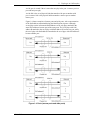
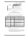
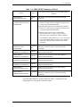
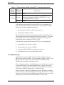
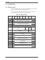
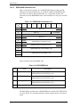
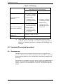
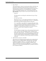
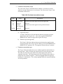
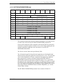
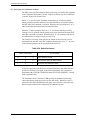
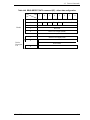
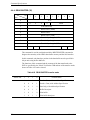
Table 1.4 OOB signal timing specifications
Parameter
Minimum
OOB interval
(OOBI) *1
666,600 ps
COMSAS detect
timeout
13,65 ìs
*1
Nominal
666,666 ps
−
Maximum
Comments
666,733 ps
The time basis for burst times and
idle times used to create OOB
signals. Based on 1,5 Gbps clock
tolerance.
−
The minimum time a receiver shall
allow to detect COMSAS after
transmitting COMSAS.
Derived from: OOBI × 512 × 40
The OOBI is different from the UI (OOB) defined in SATA (for example,
stricter clock tolerance applies to SAS). This is because the OOBI is a
fixed value that is equal to the UI value of G1, and that does not depend on
actual transfer speed used to set up the burst time.
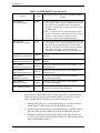
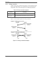
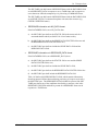
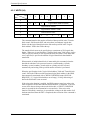
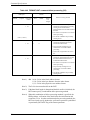
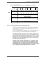
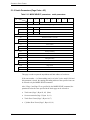
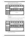
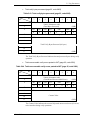
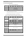
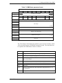
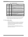
Table 1.5 describes the OOB signal transmitter requirements for the burst time,
idle time, and negation times that comprise each OOB signal.
C141-C013
33
SAS Interface
Table 1.5 OOB signal transmitter requirements
Signal
Burst time
Idle time
Negation time
COMINIT/RESET
160 OOBI
480 OOBI
800 OOBI
COMSAS
160 OOBI
1440 OOBI
2400 OOBI
To transmit an OOB signal, a transmitter shall repeat these steps six times:
1) transmit D.C. idle for an idle time; and
2) transmit an ALIGN burst for a burst time.
It shall then transmit D.C. idle for an OOB signal negation time.
The ALIGNs used in OOB signals should be at generation 1 (G1) physical link rates
(i.e., 1,5 Gbps). The ALIGNs are only required to generate an envelope for the
detection circuitry, as required for any signaling that may be A.C. coupled. If G2
ALIGNs are used, the number of ALIGNs doubles compared with G1 ALIGNs.
A SAS transmitter should transmit ALIGNs at the G1 physical link rate to create
the burst portion of the OOB signal, but may transmit ALIGNs at its lowest
supported physical link rate if it is not able to transmit at the G1 physical link rate
and shall not transmit them at a physical link rate faster than its lowest supported
physical link rate.
Figure 1.8 describes OOB signal transmission by the SP transmitter.
COMRESET/COMINIT
ALIGN burst
1
2
3
2
1
3
4
4
5
5
6
6
COMINIT
negation
COMINIT
idle
ALIGN burst
1
1
COMINIT
Transmitt
COMSAS
2
2
3
3
4
4
5
5
COMSAS
Transmitted
6
6
COMSAS
negation
COMSAS idle
Figure 1.8 OOB signal transmission
34
C141-C013
1.3 Phy layer
Table 1.6 describes the OOB signal receiver requirements for detecting burst
times, assuming Tburst is the length of the detected burst time. The burst time is
not used to distinguish between signals.
Table 1.6 OOB signal receiver burst time detection requirements
Signal
Detection requirements
may detect
shall detect
COMINIT/COMRESET
Tburst ≤ 100 ns
Tburst > 100 ns
COMSAS
Tburst ≤ 100 ns
Tburst > 100 ns
Table 1.7 describes the OOB signal receiver requirements for detecting idle times,
assuming Tidle is the length of the detected idle time.
Table 1.7 OOB signal receiver idle time detection requirements
Signal
Detection requirements
may detect
shall detect
COMINIT/COMRESET
175 ns ≤ Tidle < 525 ns
304 ns ≤ Tidle < 336 ns
COMSAS
525 ns ≤ Tidle < 1575 ns
911,7 ns ≤ Tidle < 1008 ns
Table 1.8 describes the OOB signal receiver requirements for detecting negation
times, assuming Tidle is the length of the detected idle time.
Table 1.8 OOB signal receiver negation time detection requirements
Signal
Detection requirements
COMINIT/COMRESET
Tidle > 525 ns
COMSAS
Tidle > 1575 ns
A receiver shall detect an OOB signal after receiving four consecutive idle
time/burst time pairs. It is not an error to receive more than four idle time/burst
time pairs. A receiver shall not detect the same OOB signal again until it has
detected the corresponding negation time (i.e., a COMINIT negation time for a
COMINIT) or has detected a different OOB signal.
A SAS receiver shall detect OOB signals comprised of ALIGNs transmitted at any
rate up to its highest supported physical link rate. This includes physical link rates
below its lowest supported physical link rate (e.g., a SAS receiver supporting only
3,0 Gbps detects 1,5 Gbps based ALIGNs, providing interoperability with a SAS
transmitter supporting both 1,5 Gbps and 3,0 Gbps).
C141-C013
35
SAS Interface
Figure 1.9 describes SAS OOB signal detection by the SP receiver.
COMRESET/COMINIT
1
2
3
4
Any transitions
n
COMINIT
negation
COMINIT
detected
COMSAS
2
1
3
4
n
COMSAS
negation
Any transitions
n
idle
ALIGN burst
nth
idle/Burst pair
COMSAS
detected
idle/Burst pair
Figure 1.9 OOB signal detection
1.3.5 SAS OOB sequency
During the OOB sequence, the INIT and the drive first send the COMINIT signal
to each other, then the COMSAS signal. When they both have received the
COMSAS signal from each other, the OOB sequence is recognized as having been
performed successfully. Depending on the power-on timing, reception of the
COMINIT signal from the other side may not be detected. In such a case,
however, the OOB sequence is recognized as having been performed successfully
if the COMINIT and COMSAS signals have been sent by the time the COMSAS
signal from the other side is received.
When the OOB sequence is successful, the SAS speed negotiation sequence starts.
Figure 1.10 shows several different SAS OOB sequences between phy A and phy
B, with phy A starting the SAS OOB sequence at the same time as phy B, before
phy B, and before phy B powers on.
36
C141-C013
1.3 Phy layer
Scenario 1: Both SAS phys start SAS OOB sequence at same time
COMINIT
Phy A Tx/
Phy B Rx
COMSAS
A
Time=0
Phy A Rx/
Phy B Tx
Time=z
B
COMINIT
COMSAS
Scenario 2: SAS phy A starts SAS OOB sequence
COMINIT
Phy A Tx/
Phy B Rx
COMSAS
A
Time=0
Phy A Rx/
Phy B Tx
Time=z
B
COMINIT
COMSAS
Scenario 3: SAS phy B misses SAS phy A's COMINIT
COMINIT
Phy A Tx/
Phy B Rx
COMSAS
A
Time=0
Phy A Rx/
Phy B Tx
Time=z
B
COMINIT
A:
B:
Time 0 :
Time z :
COMSAS
SAS phy A power on
SAS phy B power on
SAS phy reset sequence begins
SAS speed negotiation sequence begins
Figure 1.10 SAS to SAS OOB sequence
C141-C013
37
SAS Interface
1.3.5.1
Exception handling in the OOB sequence
•
When the COMINIT signal cannot be detected
When a drive sends the COMINIT signal but the COMINIT signal from the
other side cannot be detected, the drive waits for the reception of the
COMINIT signal from the INIT or expander until the hot-plug timeout time
(500 ms) elapses. If the hot-plug timeout time elapses before the COMINIT
signal from the other side has been received, the drive sends the COMINIT
signal again to start a new link reset sequence. If the drive receives the
COMSAS signal while waiting for the COMINIT signal, it sends the
COMSAS signal and takes the OOB sequence as having been performed
successfully in spite of the fact that it has not received the COMINIT signal.
•
When the COMSAS signal cannot be detected
When a drive sends the COMSAS signal but the COMSAS signal from the
other side cannot be detected, the drive waits for the reception of the
COMSAS signal from the INIT or expander until the hot-plug timeout time
(500 ms) elapses. If the hot-plug timeout time elapses before the COMSAS
signal from the other side has been received, the drive sends the COMSAS
signal again to start a new link reset sequence.
1.3.6 SAS speed negotiation sequence
The SAS speed negotiation sequence is a peer-to-peer negotiation technique that
does not assume initiator and target (i.e., host and device) roles. The sequence
consists of a set of speed negotiation windows for each physical link rate, starting
with 1,5 Gbps, then 3,0 Gbps, then the next rate. The length of the speed
negotiation sequence is determined by the number of physical link rates supported
by the phys.
Figure 1.11 defines the speed negotiation window, including:
a)
speed negotiation window time;
b) rate change delay time (RCDT);
c)
speed negotiation transmit time (SNTT); and
d) speed negotiation lock time (SNLT).
38
C141-C013
1.3 Phy layer
ALIGN(0)s
ALIGN(1)s
Speed negotiation lock time(SNLT)
Rate change delay time
(RCDT)
Speed negotiation transmit time(SNTT)
Speed negotiation window
Figure 1.11 SAS speed negotiation window
Table 1.9 defines the timing specifications for the SAS speed negotiation
sequence.
Table 1.9 SAS speed negotiation sequence timing specifications
Parameter
Time
Comments
750 000 OOBI
The time the transmitter shall transmit D.C.
idle between rates during speed negotiation.
163 840 OOBI
The time during which ALIGN(0) or
ALIGN(1) is transmitted at each physical link
rate during the speed negotiation sequence.
Derived from: OOBI x 4096 x 40.
Speed negotiation
lock time (SNLT)
153 600 OOBI
The maximum time during the speed
negotiation window for a transmitter to reply
with ALIGN(1). Derived from:
OOBI x 3840 x 40
Speed negotiation
window time
913 840 OOBI
The duration of a speed negotiation window.
Derived from: RCDT + SNTT.
Rate change delay
time (RCDT)
Speed negotiation
transmit time (SNTT)
The speed negotiation sequence shall consist of the following transmission
sequence:
1) a transmission of D.C. idle for an RCDT; and
2) if the phy supports the physical link rate, a transmission of ALIGNs at that
physical link rate for the remainder of the entire speed negotiation window. If
the phy does not support the physical link rate, transmission of D.C. idle for
the remainder of the entire speed negotiation window.
C141-C013
39
SAS Interface
If the phy supports the physical link rate, it shall attempt to synchronize on an
incoming series of dwords at that rate for the SNLT. The received dwords may be
ALIGN (0) or ALIGN (1) primitives. If the phy achieves dword synchronization
within the SNLT, it shall change from transmitting ALIGN (0) primitives to
transmitting ALIGN (1) primitives for the remainder of the SNTT (i.e., the
remainder of the speed negotiation window). If the phy does not achieve dword
synchronization within the SNLT, it shall continue transmitting ALIGN (0)s for
the remainder of the SNTT (i.e., the remainder of the speed negotiation window).
At the end of the SNTT, if a phy is both transmitting and receiving ALIGN (1)
primitives, it shall consider that physical link rate valid. The phy shall then
proceed to the next speed negotiation window. A phy shall participate in all speed
negotiation windows:
a)
up to its highest supported physical link rate plus one; or
b) until it runs a speed negotiation window that does not detect a valid physical
link rate after having detected a valid physical link rate in a previous speed
negotiation window.
If the phy has detected a valid physical link rate in the previous speed negotiation
window, it shall enter the final speed negotiation window using the highest
previously successful link rate.
Figure 1.12 shows speed negotiation between a phy A that supports G1 through
G3 link rates and a phy B that only supports the G2 link rate. Both phys run:
1) the G1 speed negotiation window, supported by phy A but not by phy B;
2) the G2 speed negotiation window, supported by both phys; and
3) the G3 speed negotiation window, supported by phy A but not by phy B.
Both phys then select G2 for the final speed negotiation window to establish the
negotiated physical link rate.
40
C141-C013
1.3 Phy layer
no dword
sync
RCD
dword
sync
RCD
no dword
sync
SNTT
SNTT
Phy A Tx/
RCD
RCD
SNTT
dword
sync
SNTT
Phy B Rx
RCD
RCD
dword
sync
SNTT
SNTT
Phy A Rx/
Phy B Tx
RCD
SNTT
Not supported
Not supported
by phy B
by phy B
G1 rate
G2 rate
G3 rate
dword
sync
SNTT
G2 rate
(negotiated rate)
Time z: SAS speed negotiation sequence begins
ALIGN(0)s
ALIGN(1)s
Time
Figure 1.12 SAS speed negotiation sequence (Example 1)
If the phy does not obtain dword synchronization during the final speed negotiation
window, the SAS speed negotiation sequence fails.
Figure 1.13 shows the same speed negotiation sequence as in Figure 1.12 when phy B
does not obtain dword synchronization during the final speed negotiation window. If
this occurs, the handshake is not complete and the OOB sequence shall be retried
starting with COMINIT, forcing the phy to retry the whole reset sequence.
RCD
dword
sync
SNTT
RCD
dword
sync
SNTT
no dword
sync
RCD
SNTT
Phy A Tx/
dword
sync
COMINIT
SNTT
Phy B Rx
RCD
dword
sync
SNTT
RCD
dword
sync
SNTT
RCD
RCD
SNTT
no dword
sync
COMINIT
SNTT
Phy A Rx/
Phy B Tx
G1 rate
ALIGN(0)s
G2 rate
ALIGN(1)s
G3 rate
G2 rate
(negotiated rate)
Hot Plug
Timeout delay
Time z: SAS speed negotiation sequence begins
Time
Figure 1.13 SAS speed negotiation sequence (Example 2)
C141-C013
41
SAS Interface
1.3.6.1
Phy reset sequence after devices are attached
Since SAS signal cable connector does not include power lines, it is not possible
to detect the physical insertion of the signal cable connector onto a plug. Noncabled environments may similarly not have a way to detect physical insertion of
a device. As a result, every time a phy reset sequence is originated:
Figure 1.14 shows how two phys complete the phy reset sequence if the phys are
not attached at power on. In this example, phy A and phy B are attached some
time before phy B's second hot-plug timeout occurs. Phy B's OOB detection
circuitry detects a COMINIT after the attachment, and therefore phy B transmits
COMSAS, since it has both transmitted and received a COMINIT. Upon
receiving COMSAS, phy A transmits its own COMSAS. The SAS speed
negotiation sequence follows.
COMINIT Hot-Plug COMINIT Hot-Plug
Timeout
Phy A Tx
COMINIT
COMSAS
Timeout
A
Time=0
Time=y
Time=z
Phy A Rx
B
Incomplete
COMINIT
COMSAS
COMINIT Hot-Plug COMINIT
COMSAS
Timeout
Phy B Tx
B
Time=0
Time=z
Time=y
Phy B Rx
A
COMINIT
A:
B:
Time y :
Time z:
COMSAS
SAS phy A power on
SAS phy B power on
SAS phy A attached to SAS phy B
SAS phy A and SAS phy B start the SAS speed negotiation sequence
Figure 1.14 Phy reset sequence (Example)
42
C141-C013
1.3 Phy layer
1.3.6.2
When the speed negotiation sequence is successful
When the speed negotiation sequence is successful, the identification sequence
(sending and receiving the IDENTIFY frame) is performed subsequently.
However, the INIT may have started the hard reset sequence at the time when the
drive starts the identification sequence. In this case, the drive will start the link
reset sequence, because it receives the HARD_RESET.
1.3.6.3
Exception handling in the speed negotiation sequence
•
When synchronization cannot be established at the G1 or G2 rate
•
When synchronization cannot be established at the last negotiated rate
In both of the cases referred to above, the speed negotiation sequence is
considered to have failed. The drive waits for the reception of the COMINIT
signal from the INIT or expander until the hot-plug timeout time (500 ms) elapses.
When the hot-plug timeout time elapses before the signal has been received from
the other side, the drive sends the COMINIT signal again to start a new link reset
sequence. At the same time, the value in the PHY RESET PROBLEM field of the
Protocol-Specific log page (page 18) is incremented when synchronization cannot
be established at the last negotiated rate.
1.3.7 Phy layer dword synchronization (DWS)
The dword synchronization monitoring performed by the drive after the
completion of the speed negotiation sequence has the following characteristics:
1) When four invalid dwords are detected in a frame (address frame or SSP
frame), the dword synchronization is considered to have been lost. At this
time, the drive starts the link reset sequence without monitoring whether any
valid primitive is received (and without trying to establish resynchronization).
2) If an invalid dword is detected in the idle state (the state where random data
is being sent and/or received without transfer of frames or primitives), the
DWS Reset timeout timer (1 ms) is started. If at least one valid primitive is
detected within 1 ms, the monitoring assumes that the drive is in the
SynAcquired state (the state that the dword synchronization is established).
Otherwise, the drive starts the link reset sequence.
C141-C013
43
SAS Interface
1.4 Link layer
The link layer defines primitives, address frames, and connections.
1.4.1 Primitives
Table 1.10 defines the primitives not specific to the type of connection.
Table 1.10 Primitives not specific to type of connection (1/2)
From
Primitive
To
Sequence
USE (*4)
I
E
T
I
E
T
Type
SAS 1.1
FJ supported
rev. 10
prim
supported prim
AIP (NORMAL)
NoConn
-
E
-
I
E
T
single
supported
supported
AIP (RESERVED 0)
NoConn
-
-
-
I
E
T
single
↑
Supported (*1)
AIP (RESERVED 1)
NoConn
-
-
-
I
E
T
single
↑
Supported (*1)
AIP (RESERVED 2)
NoConn
-
-
-
I
E
T
single
↑
Supported (*1)
AIP (WAITING ON CONNECTION)
NoConn
-
E
-
I
E
T
single
supported
supported
AIP (WAITING ON DEVICE)
NoConn
-
E
-
I
E
T
single
supported
supported
AIP (WAITING ON PARTIAL)
NoConn
-
E
-
I
E
T
single
supported
supported
AIP (RESERVED WAITING ON PARTIAL)
NoConn
-
-
-
I
E
T
single
↑
Supported (*1)
ALIGN (0)
ALL
I
E
T
I
E
T
single
supported
supported
ALIGN (1)
ALL
I
E
T
I
E
T
single
supported
supported
ALIGN (2)
ALL
I
E
T
I
E
T
single
supported
supported
ALIGN (3)
ALL
I
E
T
I
E
T
single
supported
supported
BREAK
ALL
I
E
T
I
E
T
redundant
supported
supported
BROADCAST (CHANGE)
NoConn
I
E
-
I
E
T
redundant
supported
ignored
BROADCAST (RESERVED CHANGE 0)
NoConn
-
-
-
I
E
T
redundant
↑
ignored
BROADCAST (RESERVED CHANGE 1)
NoConn
-
-
-
I
E
T
redundant
↑
ignored
BROADCAST (SES)
NoConn
-
-
T
I
E
T
redundant
supported
ignored
BROADCAST (RESERVED 1)
NoConn
-
-
-
I
E
T
redundant
reserved
ignored
BROADCAST (RESERVED 2)
NoConn
-
-
-
I
E
T
redundant
reserved
ignored
BROADCAST (RESERVED 3)
NoConn
-
-
-
I
E
T
redundant
reserved
ignored
BROADCAST (RESERVED 4)
NoConn
-
-
-
I
E
T
redundant
reserved
ignored
CLOSE (NORMAL)
Conn
I
-
T
I
-
T
triple
supported
supported
CLOSE (RESERVED 0)
Conn
-
-
-
I
-
T
triple
↑
↑
CLOSE (RESERVED 1)
Conn
-
-
-
I
-
T
triple
↑
↑
CLOSE (CLEAR AFFILIATION)
STP
I
-
-
-
-
T
triple
44
(Not STP)
↑
C141-C013
1.4 Link layer
Table 1.10 Primitives not specific to type of connection (2/2)
From
Primitive
To
Sequence
USE (*4)
SAS 1.1
FJ supported
rev. 10
prim
supported prim
I
E
T
I
E
T
Type
NoConn
I
E
T
I
E
T
single
supported
supported
ALL
-
E
-
I
E
T
single
supported
supported
NoConn
I
E
-
I
E
T
redundant
supported
supported
NOTIFY (ENABLE SPINUP)
ALL
I
E
-
I
E
T
single
supported
supported
NOTIFY (RESERVED 0)
ALL
-
-
-
I
E
T
single
reserved
ignored
NOTIFY (RESERVED 1)
ALL
-
-
-
I
E
T
single
reserved
ignored
NOTIFY (RESERVED 2)
ALL
-
-
-
I
E
T
single
reserved
ignored
OPEN_ACCEPT
NoConn
I
-
T
I
-
T
single
supported
supported
OPEN_REJECT (RETRY)
NoConn
I
-
T
I
-
T
single
supported
supported
OPEN_REJECT (RESERVED CONTINUE 0)
NoConn
-
-
-
I
-
T
single
↑
↑
OPEN_REJECT (RESERVED CONTINUE 1)
NoConn
-
-
-
I
-
T
single
↑
↑
OPEN_REJECT (BAD DESTINATION)
NoConn
-
E
-
I
-
T
single
supported
supported
OPEN_REJECT (CONNECTION RATE NOT
SUPPORTED)
NoConn
I
E
T
I
-
T
single
supported
supported
OPEN_REJECT (NO DESTINATION)
NoConn
-
E
-
I
-
T
single
supported
supported
OPEN_REJECT (RESERVED INITIALIZE 0)
NoConn
-
-
-
I
-
T
single
↑
↑
OPEN_REJECT (RESERVED INITIALIZE 1)
NoConn
-
-
-
I
-
T
single
↑
↑
OPEN_REJECT (PATHWAY BLOCKED)
NoConn
-
E
-
I
-
T
single
supported
supported
OPEN_REJECT (RESERVED STOP 0)
NoConn
-
-
-
I
-
T
single
↑
↑
OPEN_REJECT (RESERVED STOP 1)
NoConn
-
-
-
I
-
T
single
↑
↑
OPEN_REJECT (PROTOCOL NOT
SUPPORTED)
NoConn
I
-
T
I
-
T
single
supported
supported
OPEN_REJECT (STP RESOURCES BUSY)
NoConn
-
E
T
I
-
-
single
supported
supported (*2)
OPEN_REJECT (WRONG DESTINATON)
NoConn
I
-
T
I
-
T
single
supported
supported
OPNE_REJECT (RESERVED ABANDON 0)
NoConn
-
-
-
I
-
T
single
↑
↑
OPNE_REJECT (RESERVED ABANDON 1)
NoConn
-
-
-
I
-
T
single
↑
↑
OPNE_REJECT (RESERVED ABANDON 2)
NoConn
-
-
-
I
-
T
single
↑
↑
OPNE_REJECT (RESERVED ABANDON 3)
NoConn
-
-
-
I
-
T
single
↑
↑
SOAF
NoConn
I
E
T
I
E
T
single
supported
supported
EOAF
ERROR
HARD RESET
Table 1.11 defines the primitives used only inside SSP and SMP connections.
C141-C013
45
SAS Interface
Table 1.11 Primitives used only inside SSP and SMP connections
From
Primitive
To
Sequence
USE (*4)
I
E
T
I
E
T
Type
SAS 1.1
FJ supported
rev. 10
prim
supported prim
ACK
Conn
I
-
T
I
-
T
single
supported
supported
CREDIT_BLOCKED
Conn
I
-
T
I
-
T
single
supported
supported
DONE (NORMAL)
Conn
I
-
T
I
-
T
single
supported
supported
DONE (RESERVED 0)
Conn
-
-
-
I
-
T
single
↑
supported (*3)
DONE (RESERVED 1)
Conn
-
-
-
I
-
T
single
↑
supported (*3)
DONE (ACK/NAK TIMEOUT)
Conn
I
-
T
I
-
T
single
supported
supported
DONE (RESERVED TIMEOUT 0)
Conn
-
-
-
I
-
T
single
↑
supported (*3)
DONE (RESERVED TIMEOUT 1)
Conn
-
-
-
I
-
T
single
↑
supported (*3)
DONE (CREDIT TIMEOUT)
Conn
I
-
T
I
-
T
single
supported
supported
EOF
Conn
I
-
T
I
-
T
single
supported
supported
NAK (CRC ERROR)
Conn
I
-
T
I
-
T
single
supported
supported
NAK (RESERVED 0)
Conn
-
-
-
I
-
T
single
↑
↑
NAK (RESERVED 1)
Conn
-
-
-
I
-
T
single
↑
↑
NAK (RESERVED 2)
Conn
-
-
-
I
-
T
single
↑
↑
RRDY (NORMAL)
Conn
I
-
T
I
-
T
single
supported
supported
RRDY (RESERVED 0)
Conn
-
-
-
I
-
T
single
↑
↑
RRDY (RESERVED 1)
Conn
-
-
-
I
-
T
single
↑
↑
SOF
Conn
I
-
T
I
-
T
single
supported
supported
(*1) These primitives are received as AIP primitives.
(*2) When this primitive is received, the connection request is canceled and the
command is aborted.
(*3) These primitives are received as DONE primitives.
(*4) When a primitive falling under "NoConn" is received during the inside
connection, this primitive is discarded. When a primitive falling under
"NoConn" is received during the outside connection, this primitive is also
discarded. As for the HARD_RESET primitive, when it is received at any
time except during the period between the completion of the speed
negotiation and the reception of the first valid address frame, the received
HARD_RESET primitive is discarded as well.
46
C141-C013
1.4 Link layer
1.4.2 Primitive sequences
Table 1.12 summarizes the types of primitive sequences.
Table 1.12 Primitive sequences
Primitive
sequence type
Number of times the transmitter
transmits the primitive to transmit
the primitive sequence
Number of times the receiver
receives the primitive to detect the
primitive sequence
Single
1
1
Triple
3
3
Redundant
6
3
Any number of ALIGNs and NOTIFYs may be sent inside primitive sequences
without affecting the count or breaking the consecutiveness requirements. Rate
matching ALIGNs and NOTIFYs shall be sent inside primitive sequences inside
of connections if rate matching is enabled.
1.4.3 Primitives not specific to type of connections
1.4.3.1
AIP (Arbitration in progress)
AIP is sent by an expander device after a connection request to specify that the
connection request is being processed and specify the status of the connection
request.
A drive performs the following processing when an AIP primitive is received:
1) When the drive receives an AIP primitive after sending the OPEN frame, the
drive initializes the open timer held in the drive, and restarts it.
2) When the drive receives an AIP primitive before sending the OPEN frame,
the received AIP primitive is discarded.
3) In a case of OPEN cross (a case where both the drive and initiator send the
OPEN frame), when the drive receives an AIP primitive after sending the
OPEN frame and, then, receives the OPEN frame from the expander, the
drive does not perform the arbitration fairness procedure. Instead, the
attempt from the drive is treated as unsuccessful, and the drive sends the
OPEN_ACCEPT or an OPEN_REJECT primitive.
1.4.3.2
ALIGN
ALIGNs are used for:
a)
OOB signals;
b) character and dword alignment during the speed negotiation sequence;
c)
clock skew management after the phy reset sequence;
d) rate matching during connections; and
C141-C013
47
SAS Interface
Phys shall use ALIGN (0) to construct OOB signals as described in 6.6. Phys shall
use ALIGN (0) and ALIGN (1) during the speed negotiation sequence as
described in 6.7.4.2. Phys shall rotate through ALIGN (0), ALIGN (1), ALIGN
(2), and ALIGN (3) for all ALIGNs sent after the phy reset sequence.
1.4.3.3
BREAK
The BREAK primitive is used to cancel the connection request, or to cancel the
connection. The BREAK primitive is sent in cases 1) to 4) shown below.
1) When the connection request is to be canceled after sending an OPEN frame
2) When neither OPEN_ACCEPT nor OPEN_REJECT primitive is received
within 1 ms of sending an OPEN frame
3) When neither a DONE primitive nor an SSP frame is received within 1 ms of
sending a DONE primitive
4) When a CLOSE primitive is not received within 1 ms of sending a CLOSE
primitive
When the BREAK primitive is sent in any of the cases above, the BREAK timer
(1 ms) is started in anticipation of the reception of the BREAK primitive within 1
ms. If the BREAK primitive is not received within 1 ms, the connection is
regarded as having been closed.
After the BREAK primitive is sent, when any primitives and/or frames other than
the BREAK primitive are received, all of these (except NOTIFY primitives) are
discarded.
When the BREAK primitive is not received within 1 ms of sending the BREAK
primitive, a drive may start the link reset sequence.
1.4.3.4
BROADCAST
BROADCASTs are used to notify all SAS ports in a domain of an event.
When an expander port receives a BROADCAST it shall transmit the same
BROADCAST on at least one phy in all other expander ports. BROADCAST shall
only be sent outside of connections after the phy reset sequence has completed.
BROADCAST (CHANGE) is sent by an expander device to notify SAS INIT
ports and other expander devices that a configuration change has occurred.
BROADCAST (CHANGE) may also be transmitted by SAS INIT ports.
BROADCAST (CHANGE) shall be ignored by SAS TARG ports.
BROADCAST (SES) is sent by a SAS TARG port to notify SAS INIT ports that
an asynchronous event has occurred in an enclosure, and SSP INIT ports should
poll all the SCSI enclosure services logical units in the SAS domain.
BROADCAST (SES) shall be ignored by SAS TARG ports.
The drive ignores all received BROADCAST primitives.
48
C141-C013
1.4 Link layer
1.4.3.5
CLOSE
A CLOSE primitive is used to close a connection. When a CLOSE primitive is
sent, the close timer (1 ms) is started. If a CLOSE primitive is not received within
1 ms of sending CLOSE primitive, the BREAK primitive is sent. The recipient
must send a CLOSE primitive within 1 ms of receiving a CLOSE primitive.
Drives support only the CLOSE (NORMAL) primitive as a CLOSE primitive,
while the CLOSE (CLEAR AFFILIATION), CLOSE (RESERVED 0), and
CLOSE (RESERVED 1) primitives are ignored.
1.4.3.6
EOAF (End of address frame)
EOAF specifies the end of an address frame.
1.4.3.7
ERROR
ERROR should be sent by an expander device when it is forwarding dwords from
a SAS physical link or SATA physical link to a SAS physical link and it receives
an invalid dword or an ERROR.
When a drive receives an ERROR primitive, the drive discards it. When a
received address frame contains the ERROR primitive, the whole address frame is
discarded even if CRC is correct.
When a drive receives an SSP frame containing the ERROR primitive, the drive
discards the whole SSP frame even if CRC is correct, and sends the NAK
primitive.
1.4.3.8
HARD_RESET
HARD_RESET is used to force a phy to generate a hard reset to its port. This
primitive is only valid after the phy reset sequence without an intervening
identification sequence and shall be ignored at other times.
Upon receipt of the HARD_RESET primitive, a drive clears all the commands it
is currently holding.
In a dual port drive, the HARD_RESET primitive received at one port (e.g., at
port A) affects the other port (e.g., at port B).
Meanwhile, as can be expected, a link reset sequence that occurs at one port (e.g.,
port A) does not affect the other port (e.g., port B).
C141-C013
49
SAS Interface
1.4.3.9
NOTIFY
The NOTIFY (ENABLE SPINUP) primitive is sent by a SAS INIT device or
expander device. When receiving the NOTIFY (ENABLE SPINUP) primitive in
the active wait state of SCSI power conditions, a drive enters the active state.
A NOTIFY primitive is sometime used as a substitute for an ALIGN primitive,
and it is sent by the initiator or expander at regular intervals.
A SAS TARG device with multiple SAS TARG ports treats the NOTIFY
(ENABLE SPINUP) primitives from all the SAS TARG ports equally (for
example, the NOTIFY (ENABLE SPINUP) primitive received through SAS
TARG port A is treated as the wakeup for the START STOP UNIT command
received through SAS TARG port B).
The NOTIFY (RESERVED 0), NOTIFY (RESERVED 1), and NOTIFY
(RESERVED 2) primitives are ignored by all devices.
1.4.3.10 OPEN_ACCEPT
The OPEN_ACCEPT primitive indicates the acceptance of a connection request.
The recipient of an OPEN frame must send the OPEN_ACCEPT primitive within
1 ms, when it can accept the connection request.
1.4.3.11 OPEN_REJECT
An OPEN_REJECT primitive indicates the rejection of a connection request.
Among the OPEN_REJECT primitives, there are those indicating that the
connection request cannot be continued (OPEN_REJECT abandon primitives)
and those indicating that the connection request can be retried (OPEN_REJECT
retry primitives).
The OPEN_REJECT primitives defined in Table 1.13 direct the recipients to
abandon the connection request.
50
C141-C013
1.4 Link layer
Table 1.13 OPEN_REJECT abandon primitives
Primitive
Issuer
Processing by the drive that receives the OPEN_REJECT
primitive
OPEN_REJECT
(BAD DESTINATION)
Expander
phy
Cancels the connection request, and aborts the TASK
(command).
OPEN_REJECT
(CONNECTION RATE NOT
SUPPORTED)
Any phy
1) When the physical link rate is 3.0 Gbps and the connection
link rate is 3.0 Gbps, the drive changes the connection rate to
1.5 Gbps, and resends the OPEN frame.
2) When the physical link rate is 3.0 Gbps and the connection
link rate is 1.5 Gbps, the drive changes the connection rate to
3.0 Gbps, and resends the OPEN frame.
3) When the physical link rate is 1.5 Gbps and the
connection link rate is 1.5 Gbps, the drive cancels
connection request, and aborts the TASK (command).
* After sending an OPEN frame in case 1) or 2), if the drive
receives this OPEN_REJECT primitive again, the drive
cancels the connection request, and aborts the TASK
(command).
OPEN_REJECT
(PROTOCOL NOT
SUPPORTED)
Destination
phy
If the driver receives this OPEN_REJECT primitive, it
cancels the connection request, and aborts the TASK
(command).
OPEN_REJECT
(RESERVED ABANDON 0)
Unknown
Performs the same processing as the OPEN_REJECT
(WRONG DESTINATION).
OPEN_REJECT
(RESERVED ABANDON 0)
Unknown
Performs the same processing as the OPEN_REJECT
(WRONG DESTINATION).
OPEN_REJECT
(RESERVED ABANDON 0)
Unknown
Performs the same processing as the OPEN_REJECT
(WRONG DESTINATION).
OPEN_REJECT
(RESERVED ABANDON 0)
Unknown
Performs the same processing as the OPEN_REJECT
(WRONG DESTINATION).
OPEN_REJECT
(STP RESOURCES BUSY)
Destination
phy
Performs the same processing as the OPEN_REJECT
(WRONG DESTINATION).
OPEN_REJECT
(WRONG DESTINATION)
Destination
phy
If the driver receives this OPEN_REJECT primitive, it
cancels the connection request, and aborts the TASK
(command).
All of the OPEN_REJECT versions defined in Table 1.14 shall result in the
originating device retrying the connection request.
C141-C013
51
SAS Interface
Table 1.14 OPEN_REJECT retry primitives
Primitive
OPEN_REJECT
(NO DESTINATION)
Issuer
Expander
phy
Processing by the drive that receives the OPEN_REJECT
primitive
1) If the I_Tnexus loss timer is working, the drive leaves the
timer working. If the I_Tnexus loss timer has expired, the
drive aborts all the commands of the relevant initiator.
Otherwise, if the timer has not expired, the drive resends
the OPEN frame.
2) If the I_Tnexus loss timer is stopped and it has expired,
the drive aborts all the commands of the relevant initiator.
Otherwise, if the timer has not expired, the drive
initializes the timer and resends the OPEN frame.
OPEN_REJECT
(PATHWAY BLOCKED)
Expander
phy
1) If the I_Tnexus loss timer is working, the drive leaves the
timer working. If the I_Tnexus loss timer has expired, the
drive aborts all the commands of the relevant initiator.
Otherwise, if the timer has not expired, the drive resends the
OPEN frame. At this time, the drive increments the
PATHWAY BLOCKED COUNT field in the OPEN frame.
OPEN_REJECT
(RESERVED CONTINUE 0)
Unknown
Performs the same processing as the OPEN_REJECT
(RETRY).
OPEN_REJECT
(RESERVED CONTINUE 1)
Unknown
Performs the same processing as the OPEN_REJECT
(RETRY).
OPEN_REJECT
(RESERVED INITIALIZE 0)
Unknown
Performs the same processing as the OPEN_REJECT (NO
DESTINATION).
OPEN_REJECT
(RESERVED INITIALIZE 1)
Unknown
Performs the same processing as the OPEN_REJECT (NO
DESTINATION).
OPEN_REJECT
(RESERVED STOP 0)
Unknown
Performs the same processing as the OPEN_REJECT
(PATHWAY BLOCKED).
OPEN_REJECT
(RESERVED STOP 1)
Unknown
Performs the same processing as the OPEN_REJECT
(PATHWAY BLOCKED).
OPEN_REJECT (RETRY)
Destination
phy
Otherwise, if the I_Tnexus loss timer is working, the drive
stops the timer and resends the OPEN frame.
When an INIT sends an OPEN frame to a drive but the drive cannot accept the
connection request, the drive sends an OPEN_REJECT within 1ms. A drive
sends an OPEN_REJECT primitive in any of the following cases:
1) When the INIT port bit in a received OPEN frame is 0, the drive sends the
OPEN_REJECT (PROTOCOL NOT SUPPORTED) primitive.
2) When the PROTOCOL field in a received OPEN frame is not SSP, the drive
sends the OPEN_REJECT (PROTOCOL NOT SUPPORTED) primitive.
3) When the CONNECTION RATE field in the received OPEN frame is not
"1.5G or 3.0G", the drive sends the OPEN_REJECT (CONNECTION RATE
NOT SUPPORTED) primitive.
52
C141-C013
1.4 Link layer
4) When, in contradiction to the fact that the physical link rate is 1.5 Gbps, the
CONNECTION RATE field in a received OPEN frame is 3.0G, the drive
sends the OPEN_REJECT (CONNECTION RATE NOT SUPPORTED)
primitive.
5) A dual port drive may process requests from up to four INITs at a time for
each port. When a dual port drive holds commands from four INITs for one
of its ports, and if it receives a connection request from a fifth INIT through
the same port, the drive sends the OPEN_REJECT (RETRY) primitive.
6) When the drive cannot receive an SSP frame temporarily due to the recovery
processing of an internal drive error, the drive sends the OPEN_REJECT
(RETRY) primitive.
7) When the SAS address of a drive does not match the DESTINATION SAS
ADDRESS field in a received OPEN frame, the drive sends the
OPEN_REJECT (WRONG DESTINATION) primitive.
1.4.3.12 SOAF (Start of address frame)
SOAF specifies the start of an address frame.
C141-C013
53
SAS Interface
1.4.4 Primitives used only inside SSP and SMP connections
1.4.4.1
ACK (acknowledge)
The ACK primitive indicates that an SSP frame is received normally. When a
drive receives an SSP frame, and the CRC field in the received SSP frame is
correct, the drive sends the ACK primitive within 1 ms.
1.4.4.2
CREDIT_BLOCKED
The CREDIT_BLOCKED primitive indicates that no more credits can be sent
during this connection. When a drive determines that it can give out no more
credits during the connection, the drive sends the CREDIT_BLOCKED primitive
to avoid credit timeout. A drive sends the CREDIT_BLOCKED primitive in any
of the following cases:
1) When the drive sends an OPEN frame and, then, receives the OPEN_ACCEPT
primitive from the initiator during the abort processing in the drive, the drive
sends the CREDIT_BLOCKED primitive instead of an RRDY primitive.
2) When the drive determines during the connection that it has entered a
condition where abort processing inside the drive is necessary, if an SSP
frame is received from the initiator, the drive sends the CREDIT_BLOCKED
primitive instead of an RRDY primitive.
After sending the CREDIT_BLOCKED primitive, the drive must wait until the
connection is closed before it can send an RRDY primitive.
Meanwhile, when a drive receives the CREDIT_BLOCKED primitive from the
initiator, the drive performs any of the following processing:
1) At the time of the receipt of the CREDIT_BLOCKED primitive, if the drive
holds credits that have been given before and has frames to send, the drive
can send as many frames as there are credits being held at this time.
2) At the time of the receipt of the CREDIT_BLOCKED primitive, if the drive holds
credits that have been given before but has no frames to send, the drive sends the
DONE (CREDIT TIMEOUT) primitive and starts the close processing.
3) At the time of the receipt of the CREDIT_BLOCKED primitive, if the drive
holds no credits, it sends the DONE (CREDIT TIMEOUT) primitive and
starts the close processing.
1.4.4.3
DONE
A DONE primitive indicates the start of the close processing of an SSP
connection. In the close processing, in principle, when no frame for processing
remains on the side of the OPEN frame sender (recipient of the OPEN_ACCEPT
primitive), a DONE primitive is sent. However, there is no rule concerning which
side should first start the close processing.
Table 1.15 contains DONE primitive definitions.
54
C141-C013
1.4 Link layer
Table 1.15 DONE primitives
primitive
Description
DONE
(ACK/NAK TIMEOUT)
When the sender of an SSP frame does neither receive the
ACK nor the NAK primitive after sending the SSP frame, the
sender sends the DONE (ACK/NAK TIMEOUT) primitive.
DONE
(RESERVED TIMEOUT 0)
This primitive is processed in the same manner as the DONE
(ACK/NAK TIMEOUT) primitive.
DONE
(RESERVED TIMEOUT 1)
This primitive is processed in the same manner as the DONE
(ACK/NAK TIMEOUT) primitive.
DONE (NORMAL)
Indicates that all frames have been sent.
DONE (RESERVED 0)
This primitive is processed in the same manner as the DONE
(NORMAL) primitive.
DONE (RESERVED 1)
This primitive is processed in the same manner as the DONE
(NORMAL) primitive.
DONE (CREDIT
TIMEOUT)
When the wait time for an RRDY primitive has exceeded 1
ms, or the CREDIT BLOCKED primitive is received before
an RRDY primitive is received, if the close processing is
performed, the DONE (CREDIT TIMEOUT) primitive is
sent.
A drive sends a DONE primitive in any of the following cases:
1) When the drive sends an OPEN frame and establishes connection, and it
becomes that there are no frame to be sent, the drive sends the DONE
(NORMAL) primitive.
2) When credit timeout is detected before the drive sends an SSP frame, the
drive sends the DONE (CREDIT TIMEOUT) primitive.
3) When the drive receives the CREDIT_BLOCKED primitive during an inside
connection, the drive sends the DONE (CREDIT TIMEOUT) primitive
during the close processing.
4) When an OPEN frame is sent by an initiator, connection is established, and
no SSP frame has been sent for more than 1 ms, the drive sends the DONE
(NORMAL) primitive.
5) When the drive sends a read DATA frame, and data burst size of the data that
has been sent by the drive since connection establishment reaches 64 Kbytes,
the drive sends the DONE (NORMAL) primitive to temporarily close the
connection.
6) When the drive detects Ack/Nak timeout, the drive sends the DONE
(ACK/NAK TIMEOUT) primitive.
Before sending the DONE primitive, a drive starts the done timer (1 ms). Later,
when receiving an SSP frame from the initiator, the drive initializes the done
timer and restarts it. If the drive has received neither the SSP frame nor the
DONE primitive for 1 ms since sending the DONE primitive, the drive sends the
BREAK primitive.
C141-C013
55
SAS Interface
Meanwhile, when a drive receives the DONE primitive, the drive performs the
following processing:
1) If the drive has SSP frames to send at the time of the receipt of the DONE
primitive from the initiator, the drive can send as many SSP frames as there
are credits being held at this time.
2) If the drive has no SSP frames to send at the time of the receipt of the DONE
primitive from the initiator, the drive sends the DONE (NORMAL) primitive.
The side that has sent the DONE primitive cannot send the SSP primitive until
connection is established again after the current connection is temporarily closed.
1.4.4.4
EOF (End of frame)
EOF specifies the end of an SSP or SMP frame.
1.4.4.5
NAK (negative acknowledgement)
The NAK primitive indicates that an SSP frame cannot be received normally.
When a drive receives an SSP frame, and the drive detects a CRC error after
checking the CRC field in the SSP frame, the drive sends the NAK primitive.
If a received SSP frame contains the ERROR primitive or an invalid dword, the
drive sends the NAK primitive even if the CRC field in the SSP field is correct.
1.4.4.6
RRDY
During connection, when a drive detects the state where it can receive an SSP
frame, the drive sends an RRDY primitive to indicate that the connecting
companion can send the SSP frame.
When the OPEN_ACCEPT primitive is transferred, a drive will send up to three
RRDY primitives.
The sending side of the SSP frame cannot receive the SSP frame before sending
RRDY primitives (before the sending side obtains credits). If a drive receives
more SSP frames than the RRDY primitives it has sent, the drive discards the
surplus SSP frames.
1.4.4.7
SOF (Start of frame)
SOF specifies the start of an SSP or SMP frame.
56
C141-C013
1.4 Link layer
1.4.5 Clock skew management
The internal clock for a device is typically based on a PLL with its own clock
generator and is used when transmitting dwords on the physical link. When
receiving, however, dwords need to be latched based on a clock derived from the
input bit stream itself. Although the input clock is nominally a fixed frequency, it
may differ slightly from the internal clock frequency up to the physical link rate
tolerance. Over time, if the input clock is faster than the internal clock, the device
may receive a dword and not be able to forward it to an internal buffer; this is
called an overrun. If the input clock is slower than the internal clock, the device
may not have a dword when needed in an internal buffer; this is called an
underrun.
To solve this problem, transmitting devices insert ALIGNs or NOTIFYs in the
dword stream.
A phy that is the original source for the dword stream (i.e., a phy that is not an
expander phy forwarding dwords from another expander phy) shall insert one
ALIGN or NOTIFY for clock skew management as described in Table 1.16.
Table 1.16 Clock skew management ALIGN insertion requirement
Physical link rate
requirement
1.5 Gbps
One ALIGN or NOTIFY within every 2 048 dwords
3.0 Gbps
Two ALIGNs or NOTIFYs within every 4 096 dwords
In the clock skew management of a drive, one ALIGN primitive is always inserted
every 1024 dwords regardless of the physical link rate.
1.4.6 Idle physical link
In any of the conditions below, when there is no dword to be sent, an idle dword
is sent. This idle dword is scrambled.
1) In an outside connection
2) The SSP or SMP connection is an inside connection.
C141-C013
57
SAS Interface
1.4.7 Scrambling
Scrambling is used to reduce the probability of long strings of repeated patterns
appearing on the physical link.
All data dwords are scrambled. Table 1.17 lists the scrambling for different types
of data dwords.
Table 1.17 Scrambling for different data dword types
connection state
Data dword type
Outside connections SAS idle dword
Inside SSP
connection
Description of scrambling
When a connection is not open and there are no
other dwords to transmit, vendor-specific
scrambled data dwords shall be transmitted.
Address frame
After an SOAF, all data dwords shall be
scrambled until the EOAF.
SSP frame
After an SOF, all data dwords shall be
scrambled until the EOF.
SSP idle dword
When there are no other dwords to transmit,
vendor-specific scrambled data dwords shall be
transmitted.
To generate scrambled values that are to be encoded and transferred on the
physical link layer, dwords to be sent are XOR-ed with the predefined pattern. If
there is no transmission error, the received data of the dwords is XOR-ed with the
same pattern after being decoded so that the dword values of the original data can
be obtained.
The pattern that is XOR-ed with the data dwords is defined by the output of a
linear feedback shift register implemented with the following polynomial:
G(x) = x 16 + x 15 + x
13
+x4+1
The value of the linear feedback shift register shall be initialized at each SOF and
SOAF to FFFFh.
58
C141-C013
1.5 Address frames
1.5 Address frames
1.5.1 Address frames overview
Address frames are used for the identification sequence and for connection
requests. The address frame follows an SOAF and ends with an EOAF. Address
frames shall only be sent outside connections. Address frames shall not be
terminated early. All data dwords in an address frame shall be scrambled.
Table 1.18 defines the address frame format.
Table 1.18 Address frame format
Bit
Byte
0
1
27
28
31
7
6
5
4
3
2
1
0
ADDRESS FRAME TYPE
Frame Type dependent bytes
(MSB)
CRC
(LSB)
The ADDRESS FRAME TYPE field indicates the type of the address frame as
follows:
•
An ADDRESS FRAME TYPE field value of "0" indicates an IDENTIFY
address frame.
•
An ADDRESS FRAME TYPE field value of "1" indicates an OPEN address
frame.
The CRC field contains the CRC value calculated for all the data of an address
frame (data from the beginning of the frame to the byte preceding the CRC field).
If an address frame has an undefined ADDRESS FRAME TYPE, has an incorrect
frame length (longer or shorter than 7 dwords + the CRC length), or has a CRC
error, the recipient discards the frame.
C141-C013
59
SAS Interface
1.5.2 IDENTIFY address frame
Table 1.19 defines the IDENTIFY address frame format used for the identification
sequence. The IDENTIFY address frame is sent after the phy reset sequence
completes if the physical link is a SAS physical link.
Table 1.19 IDENTIFY address frame format
Bit
Byte
0
7
6
Restricted
(for Open
address
frame)
5
4
3
DEVICE TYPE
1
2
1
0
ADDRESS FRAME TYPE (0h)
Restricted (for OPEN address frame)
2
Reserved
3
Reserved
4
Restricted
SSP
STP
SMP
(for Open
INITIATOR INITIATOR INITIATOR
address
PORT
PORT
PORT
frame)
Restricted
SSP
STP
SMP
(for Open
TARGET TARGET TARGET
address
PORT
PORT
PORT
frame)
Restricted (for Open address frame)
11
12
SAS ADDRESS
19
20
PHY IDENTIFIYR
21
Reserved
27
28
(MSB)
CRC
31
(LSB)
The DEVICE TYPE field specifies the type of device containing the phy, and is
defined in Table 1.20.
Table 1.20 DEVICE TYPE field
Code
Description
001b
End device
010b
Edge expander device
011b
Fanout expander device
All others
Reserved
The ADDRESS FRAME TYPE field shall be set to 0h.
60
C141-C013
1.5 Address frames
An SSP INITIATOR PORT bit set to one specifies that an SSP INIT port is
present. An SSP INITIATOR PORT bit set to zero specifies that an SSP INIT port
is not present. Expander devices shall set the SSP INITIATOR PORT bit to zero.
An SSP TARGET PORT bit set to one specifies that an SSP TARG port is
present. An SSP TARGET PORT bit set to zero specifies that an SSP TARG port
is not present. Expander devices shall set the SSP TARGET PORT bit to zero.
For SAS ports, the SAS ADDRESS field specifies the port identifier of the SAS
port transmitting the IDENTIFY address frame. For expander ports, the SAS
ADDRESS field specifies the device name of the expander device transmitting the
IDENTIFY address frame.
The PHY IDENTIFIER field specifies the phy identifier of the phy transmitting
the IDENTIFY address frame.
A wide port shall set the DEVICE TYPE field, SSP INITIATOR PORT bit, STP
INITIATOR PORT bit, SMP INITIATOR PORT bit, SSP TARGET PORT bit,
STP TARGET PORT bit, and SMP TARGET PORT bit to the same set of values
on each phy in the wide port. Recipient ports need not check the consistency of
these fields across phys.
The contents of the IDENTIFY address frame sent by a drive are as follows:
a)
ADDRESS FRAME TYPE:
b) DEVICE TYPE:
001b
c)
SSP INITIATOR PORT bit:
0b
d) STP INITIATOR PORT bit:
0b
e)
SMP INITIATOR PORT bit:
0b
f)
SSP TARGET PORT bit:
1b
g) STP TARGET PORT bit:
0b
h) SMP TARGET PORT bit:
0h
i)
SAS ADDRESS:
Refer to the Section 1.2.1, "SAS address."
j)
PHY IDENTIFIER:
port A (0h)/port B (1h)
k) Reserved:
C141-C013
0h
0h
61
SAS Interface
1.5.3 OPEN address frame
Table 1.21 defines the OPEN address frame format used for connection requests.
Table 1.21 OPEN address frame format
Bit
Byte
0
7
INITIATO
R PORT
1
2
6
5
4
3
PROTOCOL
2
1
0
ADDRESS FRAME TYPE (1h)
FEATURES
CONNECTION RATE
(MSB)
INITIATOR CONNECTION TAG
3
(LSB)
4
DESTINATION SAS ADDRESS
11
12
SOURCE SAS ADDRESS
19
20
COMPATIBLE FEATURES
21
PATHWAY BLOCKED COUNT
22
(MSB)
ARBITRARION WAIT TIME
23
24
MORE COMPATIBLE FEATURES
27
28
(LSB)
(MSB)
CRC
31
(LSB)
An INITIATOR PORT bit set to one specifies that the source port is acting as a
SAS INIT port. An INITIATOR PORT bit set to zero specifies that the source
port is acting as a SAS TARG port.
The PROTOCOL field specifies the protocol for the connection being requested
and is defined in Table 1.22.
Table 1.22 PROTOCOL field
62
Code
Description
000b
SMP
001b
SSP
010b
STP
All others
Reserved
C141-C013
1.5 Address frames
The ADDRESS FRAME TYPE field shall be set to 1h.
The FEATURES field shall be set to zero.
The CONNECTION RATE field specifies the connection rate being requested
between the source and destination, and is defined in Table 1.23.
Table 1.23 CONNECTION RATE field
Code
Description
8h
1,5 Gbps
9h
3,0 Gbps
All others
Reserved
When requesting a connection to a SAS TARG port, a SAS INIT port shall set the
CONNECTION RATE field to a value supported by at least one potential
pathway.
When requesting an SSP connection to an SSP INIT port, an SSP TARG port
shall set the CONNECTION RATE field to the connection rate in effect when the
command was received unless it has received an OPEN_REJECT
(CONNECTION RATE NOT SUPPORTED).
The INITIATOR CONNECTION TAG field is used when the SAS TARG port
issues a connection request. This field is used as a substitute for the SAS address
of the SAS TARG port when the SAS INIT port searches for processing in
progress. If the initiator port does not require field support from the SAS TARG
port, the INITIATOR CONNECTION TAG field is set to FFFFh. If the initiator
port requires field support, the INITIATOR CONNECTION TAG field should be
set to the value that is peculiar to the SAS TARG port. When the SAS TARG
port issues a connection request to the SAS INIT port, the SAS TARG port must
set the INITIATOR CONNECTION TAG field to any of the following: the last
received value, the uncompleted command that has been received from the SAS
INIT port, or the value that has been set at the time of the connection request of
the task management. For all connection requests, the SAS INIT port must use
the same INITIATOR CONNECTION TAG value for the same SAS TARG port.
The SAS INIT port can change the INITIATOR CONNECTION TAG value only
when there is no command processing in progress or task management in the SAS
TARG port. The SAS TARG port does not check for consistency among
INITIATOR CONNECTION TAG fields of different connection requests from
the same SAS INIT port.
The DESTINATION SAS ADDRESS field indicates the port identifier of the
SAS port to which a connection request is being made.
The SOURCE SAS ADDRESS field indicates the port identifier of the SAS port
that has been issued an OPEN address frame.
C141-C013
63
SAS Interface
The COMPATIBLE FEATURES field is set to zero. The destination device
ignores the COMPATIBLE FEATURES field.
The PATHWAY BLOCKED COUNT field specifies the number of times the port
has retried this connection request due to receiving OPEN_REJECT (PATHWAY
BLOCKED). The port shall not increment the PATHWAY BLOCKED COUNT
value past FFh. If the port changes connection requests, it shall use a PATHWAY
BLOCKED COUNT of 00h.
The ARBITRATION WAIT TIME field specifies how long the port transmitting
the OPEN address frame has been waiting for a connection request to be accepted
or rejected. This time is maintained by the port layer in an Arbitration Wait Time
timer. For values from 0000h to 7FFFh, the Arbitration Wait Time timer
increments in one microsecond steps. For values from 8000h to FFFFh, the
Arbitration Wait Time timer increments in one millisecond steps. The maximum
value represents 32767 ms + 32768 µs. Table 1.24 describes several values of the
ARBITRATION WAIT TIME field.
Table 1.24 ARBITRATION WAIT TIME field
Code
Description
0000h
0 µs
0001h
1 µs
...
...
7FFFh
32 767 µs
8000h
0 ms + 32 768 µs
8001h
1 ms + 32 768 µs
...
FFFFh
...
32 767 ms + 32 768 µs
The MORE COMPATIBLE FEATURES field shall be set to zero. The
destination device shall ignore the MORE COMPATIBLE FEATURES field.
The contents of an OPEN address frame sent by a drive are as follows:
64
•
INITIATOR PORT bit: 0b
•
PROTOCOL:
•
CONNECTION RATE:
The CONNECTION RATE value when an initiator makes a connection request
•
INITIATOR CONNECTION TAG:
The INITIATOR CONNECTION TAG value when an initiator makes a
connection request
001b
C141-C013
1.5 Address frames
•
DESTINATION SAS ADDRESS:
The SAS address when an initiator makes a connection request
•
SOURCE SAS ADDRESS:
The SAS address of the drive
•
PATHWAY BLOCKED COUNT:
At the time of the first connection request, this field is set to 0h. Otherwise, it
indicates how many times the OPEN_REJECT (PATHWAY BLOCKED)
primitive has been received.
•
ARBITRATION WAIT TIME:
At the time of the first connection request, this field is set to 0h. When a
drive's connection request is unsuccessful due to arbitration fairness at the
time of sending an OPEN frame, this field of the next OPEN frame indicates
the time that has elapsed since the first connection request.
1.5.4 Identification and hard reset sequence
After the phy reset sequence has been completed indicating the physical link is
using SAS rather than SATA, each phy transmits either:
a)
an IDENTIFY address frame; or
b) a HARD_RESET.
Each phy receives an IDENTIFY address frame or a HARD_RESET from the phy
to which it is attached. The combination of a phy reset sequence, an optional hard
reset sequence, and an identification sequence is called a link reset sequence (See
Section 1.3.2).
If a device supports more than one phy, it shall transmit the same SAS address on
all phys for which it is capable of sharing within a port.
If a device detects the same SAS address incoming on different phys, it shall
consider those phys part of the same wide port.
If a device detects different SAS addresses incoming on different physical links, it
shall consider those physical links as independent physical links and consider
those phys part of different ports.
If a device does not receive a valid IDENTIFY address frame within 1 ms of phy
reset sequence completion, it shall restart the phy reset sequence.
If a device receives an additional IDENTIFY address frame after receiving the
first one, without an intervening phy reset sequence, it shall ignore the additional
IDENTIFY address frame.
If a phy receives a HARD_RESET, it shall be considered a reset event and cause a
hard reset (device initialization of the port) of the port containing that phy. After
a hard reset, a phy begins a link reset sequence.
C141-C013
65
SAS Interface
1.5.5 Connections
1.5.5.1
Connections overview
A connection is opened between a SAS INIT port and a SAS TARG port before
communication begins. A connection is established between one SAS INIT phy
in the SAS INIT port and one SAS TARG phy in the SAS TARG port.
SSP INIT ports open SSP connections to transmit SCSI commands, task
management functions, or transfer data. SSP TARG ports open SSP connections
to transfer data or transmit status.
Also at the SSP TARG port, an SSP connection must be established before data or
a status is sent.
The OPEN address frame is used to request that a connection be opened. AIP,
OPEN_ACCEPT and OPEN_REJECT are the responses to an OPEN address
frame. BREAK is used to abort connection requests and to unilaterally break a
connection. CLOSE is used for orderly closing a connection.
Connections use a single pathway from the SAS INIT phy to the SAS TARG phy.
While a connection is open, only one pathway shall be used for that connection.
A wide port may have separate connections on each of its phys.
1.5.5.2
Connection request
The OPEN address frame is used to open a connection from a source port to a
destination port using one source phy and one destination phy.
To make a connection request, the source port shall transmit an OPEN address
frame through an available phy. The source phy shall transmit idle dwords after
the OPEN address frame until it receives a response or aborts the connection
request with BREAK.
After transmitting an OPEN address frame, the source phy shall initialize and start
a 1 ms Open Timeout timer. Whenever an AIP is received, the source phy shall
reinitialize and restart the Open Timeout timer. Source phys are not required to
enforce a limit on the number of AIPs received before aborting the connection
request. When any connection response is received, the source phy shall
reinitialize the Open Timeout timer. If the Open Timeout timer expires before a
connection response is received, the source phy may assume the destination port
does not exist and shall transmit BREAK to abort the connection request.
The OPEN address frame flows through expander devices onto intermediate
physical links. If an expander device on the pathway is unable to forward the
connect request because none of the prospective physical links support the
requested connection rate, the expander device shall return OPEN_REJECT
(CONNECTION RATE NOT SUPPORTED). If the OPEN address frame reaches
the destination, it shall return either OPEN_ACCEPT or OPEN_REJECT.
Rate matching shall be used on any physical links in the pathway with negotiated
physical link rates that are faster than the requested connection rate.
66
C141-C013
1.5 Address frames
1.5.5.3
Connection responses
Table 1.25 lists the responses to an OPEN address frame being transmitted.
Table 1.25 Connection responses
Response
Description
AIP
Arbitration in progress. When an expander device is trying
to open a connection to the selected destination port, it
returns an AIP to the source phy. The source phy shall
reinitialize and restart its Open Timeout timer when it
receives an AIP. AIP is sent by an expander device while it
is internally arbitrating for access to an expander port.
OPEN_ACCEPT
Connection request accepted. This is sent by the destination
phy.
OPEN_REJECT
Connection request rejected. This is sent in response by the
destination phy or by an expander device.
OPEN address
frame
If the AIP primitive has been detected just before the OPEN
address frame, this indicates a top-priority connection
request, meaning that the OPEN_ACCEPT primitive or an
OPEN_REJECT primitive must be sent. If an AIP primitive
has not been detected yet, this indicates that two connection
requests have crossed over the physical link. At this time,
arbitration fairness is used to determine which request
should take priority.
BREAK
The destination port or expander port may reply with
BREAK indicating the connection is not being established.
Open Timeout
timer expires
The source phy shall abort the connection request by
transmitting BREAK.
After an OPEN_REJECT (CONNECTION RATE NOT SUPPORTED) has been
received by a SAS TARG port, the SAS TARG device shall set the connection
rate for future requests for that I_T_L_Q nexus to:
a)
the last value received in a connection request from the SAS INIT port;
b) 1,5 Gbps; or
c)
1.5.5.4
the connection rate in effect when the command was received.
Arbitration fairness
SAS supports least-recently used arbitration fairness.
(This is a service equalization method that lowers the priority of the most recently
used device, that is to say, gives higher priority to devices that have been in the
wait state for a long period of time.)
C141-C013
67
SAS Interface
Each SAS port and expander port shall include an Arbitration Wait Time timer
which counts the time from the moment when the port makes a connection request
until the request is accepted or rejected. The Arbitration Wait Time timer shall
count in microseconds from 0 µs to 32 767 µs and in milliseconds from 32 768 µs
to 32 767 ms + 32 768 µs. The Arbitration Wait Time timer shall stop
incrementing when its value reaches 32 767 ms + 32 768 µs.
SAS ports (i.e., SAS INIT ports and SAS TARG ports) shall start the Arbitration
Wait Time timer when they transmit the first OPEN address frame for the
connection request. When the SAS port retransmits the OPEN address frame (e.g.,
after losing arbitration and handling an inbound OPEN address frame), it shall set
the ARBITRATION WAIT TIME field to the current value of the Arbitration
Wait Time timer.
SAS ports should set the Arbitration Wait Time timer to zero when they transmit
the first OPEN address frame for the connection request. A SAS INIT port or
SAS TARG port may be unfair by setting the ARBITRATION WAIT TIME field
in the OPEN address frame to a higher value than its Arbitration Wait Time timer
indicates. However, unfair SAS ports shall not set the ARBITRATION WAIT
TIME field to a value greater than or equal to 8000h; this limits the amount of
unfairness and helps prevent livelocks.
The expander port that receives an OPEN address frame shall set the Arbitration
Wait Time timer to the value of the incoming ARBITRATION WAIT TIME field
and start the Arbitration Wait Time timer as it arbitrates for internal access to the
outgoing expander port. When the expander device transmits the OPEN address
frame out another expander port, it shall set the outgoing ARBITRATION WAIT
TIME field to the current value of the Arbitration Wait Time timer maintained by
the incoming expander port.
A port shall stop the Arbitration Wait Time timer and set it to zero when it wins
arbitration (i.e., it receives either OPEN_ACCEPT or OPEN_REJECT from the
destination SAS port rather than from an intermediate expander device). If a port
receives a connection request that satisfies its arbitration request (i.e., it receives
an OPEN address frame from the destination SAS port with the INITIATOR
PORT bit set to the opposite value and a matching PROTOCOL field), it shall
stop the Arbitration Wait Time timer unless it accepts the request (i.e., transmits
an OPEN_ACCEPT rather than an OPEN_REJECT).
If two connection requests pass on a physical link, the phy shall determine the
winner by comparing OPEN address frame field contents using the arbitration
priority described in Table 1.26.
Table 1.26 Arbitration priority for OPEN address frames passing on a physical link
68
Bits 79-64 (79 is MSB)
Bits 63-0 (0 is LSB)
ARBITRATION WAIT
TIME field value
SOURCE SAS ADDRESS
field value
C141-C013
1.5 Address frames
1.5.5.5
Aborting a connection request
BREAK may be used to abort a connection request. The source phy shall transmit
a BREAK after the Open Timeout timer expires or if it chooses to abort its
request for any other reason.
After transmitting BREAK, the source phy shall initialize a Break Timeout timer
to 1 ms and start the Break Timeout timer. Table 1.27 lists the responses to a
BREAK being transmitted before a connection response has been received.
Table 1.27 Abort connection responses
Response
Description
BREAK
This confirms that the connection request has been aborted.
Break Timeout
timer expires
The originating phy shall assume the connection request has
been aborted.
Figure 1.15 shows the sequence for a connection request where the Open Timeout
timer expires.
Figure 1.15 Connection request timeout example
C141-C013
69
SAS Interface
1.5.5.6
Closing a connection
CLOSE is used to close a connection of any protocol. After transmitting CLOSE,
the source phy shall initialize a Close Timeout timer to 1 ms and start the Close
Timeout timer. Table 1.28 lists the responses to a CLOSE being transmitted.
Table 1.28 Close connection responses
Response
Description
CLOSE
This confirms that the connection has been closed.
Close Timeout
timer expires
The originating phy shall attempt to break the connection.
Figure 1.16 shows example sequences for closing a connection.
Figure 1.16 Closing a connection example
70
C141-C013
1.5 Address frames
1.5.5.7
Breaking a connection
In addition to aborting a connection request, BREAK may also be used to break a
connection, in cases where CLOSE is not available. After transmitting BREAK,
the originating phy shall ignore all incoming dwords except for BREAKs.
After transmitting BREAK, the source phy shall initialize a Break Timeout timer
to 1 ms and start the Break Timeout timer. Table 1.29 lists the responses to a
BREAK being transmitted after a connection has been established.
Table 1.29 Break connection responses
Response
Description
BREAK
This confirms that the connection has been broken.
Break Timeout
timer expires
The originating phy shall assume the connection has been
broken. The originating phy may perform a link reset
sequence.
In addition to a BREAK, a connection is considered broken due to loss of dword
synchronization.
The following shall be the responses by an SSP phy to a broken connection:
a)
Received frames having no CRC error may be considered valid regardless of
whether an ACK has been transmitted in response to the frame prior to the
broken connection;
b) Transmitted frames for which an ACK has been received prior to a broken
connection shall be considered successfully transmitted; and
c)
1.5.5.8
Transmitted frames for which an ACK or NAK has not been received prior to
a broken connection shall be considered not successfully transmitted.
Rate matching
In spite of the fact that the physical link is set to 3.0 Gbps, the connection rate
(indicated in an OPEN address frame) may be 1.5 Gbps. As shown in Table 1.30,
if the transfer rate of the physical link is higher than the connection rate, ALIGN
or NOTIFY primitives must be inserted between dwords for each phy of the
pathway.
C141-C013
71
SAS Interface
Table 1.30 Rate matching ALIGN and/or NOTIFY insertion requirements
Physical
link rate
Connection
rate
1,5 Gbps
1,5 Gbps
None
1,5 Gbps
One ALIGN or NOTIFY within every 2 dwords that are not
clock skew management ALIGNs or NOTIFYs (i.e., every
overlapping window of 2 dwords)
3,0 Gbps
None
3,0 Gbps
Requirement
A phy shall start inserting ALIGNs and/or NOTIFYs for rate matching at the
selected connection rate with the first dword that is not an ALIGN or NOTIFY
inserted for clock skew management following:
a)
transmitting the EOAF for an OPEN address frame; or
b) transmitting an OPEN_ACCEPT.
The source phy transmits idle dwords including ALIGNs and NOTIFYs at the
selected connection rate while waiting for the connection response. This enables
each expander device to start forwarding dwords from the source phy to the
destination phy after forwarding an OPEN_ACCEPT.
A phy shall stop inserting ALIGNs and/or NOTIFYs for rate matching after:
a)
transmitting the first dword in a CLOSE;
b) transmitting the first dword in a BREAK;
c)
receiving an OPEN_REJECT for a connection request; or
d) losing arbitration to a received OPEN address frame.
1.5.6 SSP link layer
An SSP phy that accepts an OPEN address frame shall transmit at least one
RRDY in that connection within 1 ms of transmitting an OPEN_ACCEPT. If the
SSP phy is not able to grant credit, it shall respond with OPEN_REJECT
(RETRY) and not accept the connection request.
SSP is a full duplex protocol. An SSP phy may receive an SSP frame or primitive
in a connection while it is transmitting an SSP frame or primitive in the same
connection. A wide SSP port may send and/or receive SSP frames or primitives
concurrently on different connections (i.e., on different phys).
When a connection is open and an SSP phy has no more SSP frames to transmit
on that connection, it transmits a DONE to start closing the connection. The other
direction may still be active, so the DONE may be followed by one or more of the
following primitives: CREDIT_BLOCKED, RRDY, ACK, or NAK.
72
C141-C013
1.5 Address frames
1.5.6.1
SSP frame transmission and reception
During an SSP connection, SSP frames are preceded by SOF and followed by
EOF. The last data dword after the SOF prior to the EOF always contains a CRC.
An SSP phy checks the frame length and validity of the CRC.
Receiving phys must acknowledge ACK or NAK within 1 ms if there is no
condition for discarding frames. The ACK primitive indicates that SSP frames
have been received into a frame buffer without errors. The NAK (CRC ERROR)
primitive indicates that SSP frames have been received with a CRC error.
1.5.6.2
SSP flow control
An SSP phy uses RRDY to grant credit for permission for the other SSP phy in
the connection to transmit frames. Each RRDY increments credit by one frame.
Frame transmission decrements credit by one frame. Credit of zero frames is
established at the beginning of each connection.
SSP phys shall not increment credit past 255 frames.
To prevent deadlocks where an SSP INIT port and SSP TARG port are both
waiting on each other to provide credit, an SSP INIT port shall never refuse to
provide credit by withholding RRDY because it needs to transmit a frame itself.
It may refuse to provide credit for other reasons (e.g., temporary buffer full
conditions).
When the drive sends an OPEN frame and, then, receives the OPEN_ACCEPT
primitive from the initiator due to abort processing in the drive (e.g., when
receiving the TASK frame), the drive sends the CREDIT_BLOCKED primitive
instead of an RRDY primitive. In this way, the drive may refuse to offer credits.
If credit is zero, SSP phys that are going to be unable to provide credit for 1 ms
may send CREDIT_BLOCKED. The other phy may use this to avoid waiting
1 ms to transmit DONE (CREDIT TIMEOUT).
If credit is nonzero, SSP phys that are going to be unable to provide additional
credit for 1 ms, even if they receive frames per the existing credit, may transmit
CREDIT_BLOCKED.
After sending CREDIT_BLOCKED, an SSP phy shall not transmit any additional
RRDYs in the connection.
1.5.6.3
Interlocked frames
Table 1.31 shows which SSP frames shall be interlocked and which are noninterlocked.
One approach for successively processing frames and corresponding ACK or
NAK (responses to these frames) in a single processing unit consists of ensuring
that no new frame is sent until the response to the preceding frame is returned.
A frame processed in this way is called an interlocked frame.
C141-C013
73
SAS Interface
Table 1.31 SSP frame interlock requirements
SSP frame type
Interlock requirement
COMMAND
Interlocked
TASK
Interlocked
XFER_RDY
Interlocked
DATA
Non-interlocked
RESPONSE
Interlocked
Before transmitting an interlocked frame, an SSP phy shall wait for all SSP
frames to be acknowledged with ACK or NAK, even if credit is available. After
transmitting an interlocked frame, an SSP phy shall not transmit another SSP
frame until it has been acknowledged with ACK or NAK, even if credit is
available.
Before sending a non-interlocked frame, an SSP phy must wait for the following
frames to be acknowledged with ACK or NAK, even if credit is available:
a)
all non-interlocked frames with different tags; and
b) all interlocked frames;
After sending a non-interlocked frame, an SSP phy may send another noninterlocked frame with the same tag if credit is available. The SSP phy must not
send the following frames until all SSP frames have been acknowledged with
ACK or NAK, even if credit is available:
a)
a non-interlocked frame with a different tag; or
b) an interlocked frame;
Interlocking does not prevent sending and receiving interlocked frames
simultaneously (e.g., an SSP INIT phy can send a COMMAND frame while
receiving XFER_RDY, DATA, or RESPONSE frames for a different command).
An SSP phy may transmit primitives responding to traffic it is receiving (e.g., an
ACK or NAK to acknowledge an SSP frame, an RRDY to grant more receive
credit, or a CREDIT_BLOCKED to specify that no more RRDYs are going to be
transmitted in the connection) while waiting for an interlocked frame it
transmitted to be acknowledged. These primitives may also be interspersed
within an SSP frame.
74
C141-C013
1.5 Address frames
Of the primitives that may be inserted in SSP frames sent from the SSP INIT port
and expander port, a drive can detect the following:
a) ACK
b) NAK
c) RRDY
d) CREDIT_BLOCKED
e) NOTIFY
f) BREAK
g) ERROR
Meanwhile, the primitives that may be inserted in SSP frames sent from the drive
are as follows:
a) ACK
b) NAK
c) RRDY
d) CREDIT_BLOCKED
Figure 1.17 shows an example of the transfer of interlocked frames.
Figure 1.18 shows an example of the transfer of non-interlocked frames with the
same tag.
Figure 1.19 shows an example of the transfer of non-interlocked frames with
different tags.
Figure 1.17 Interlocked frames
C141-C013
75
SAS Interface
Figure 1.18 Non-interlocked frames with the same tag
Figure 1.19 Non-interlocked frames with different tags
1.5.6.4
Closing an SSP connection
DONE shall be exchanged prior to closing an SSP connection. There are several
versions of the DONE primitive indicating additional information about why the
SSP connection is being closed:
a)
76
DONE (NORMAL) specifies normal completion; the transmitter has no more
SSP frames to transmit;
C141-C013
1.5 Address frames
b) DONE (CREDIT TIMEOUT) specifies that the transmitter still has SSP
frames to transmit but did not receive an RRDY granting frame credit within
1 ms, or the transmitter has received a CREDIT_BLOCKED and has
consumed all RRDYs received; and
c)
DONE (ACK/NAK TIMEOUT) specifies that the transmitter transmitted an
SSP frame but did not receive the corresponding ACK or NAK within 1 ms.
As a result, the ACK/NAK count is not balanced and the transmitter is going
to transmit a BREAK in 1 ms unless the recipient replies with DONE and the
connection is closed.
If the transmitter has no more SSP frames to transmit and receives a
CREDIT_BLOCKED, it may transmit either DONE (NORMAL) or DONE
(CREDIT TIMEOUT).
After transmitting DONE, the transmitting phy initializes and starts a 1 ms DONE
Timeout timer.
After transmitting DONE, the transmitting phy shall not transmit any more SSP
frames during this connection. However, the phy may transmit ACK, NAK,
RRDY, and CREDIT_BLOCKED as needed after transmitting DONE if the other
phy is still transmitting SSP frames in the reverse direction. Once an SSP phy has
both transmitted and received DONE, it shall close the connection by transmitting
CLOSE (NORMAL).
Figure 1.20 shows the sequence for a closing an SSP connection.
Figure 1.20 Closing an SSP connection example
C141-C013
77
SAS Interface
1.6 Transport layer
1.6.1 SSP frame format
This layer defines the processing of each of a COMMAND frame, TASK frame,
DATA frame, XFER_RDY frame and RESPONSE frame.
Table 1.32 contains the definitions of the SSP frame format. An SSP frame
consists of the header part, information unit part, and CRC.
Table 1.32 SSP frame format
Bit
Byte
0
1
3
4
5
7
2
1
HASHED DESTINATION SAS ADDRESS
HASHED SOURCE SAS ADDRESS
0
(LSB)
(LSB)
RETRY
CHANGING
RETRADATA
DATA
NSMIT
FRAMES
POINTER
Reserved
NUMBER OF FILL
BYTES
Reserved
12
13
23
24
3
Reserved
Reserved
11
19
20
4
Reserved
(MSB)
10
17
18
5
FRAME TYPE
(MSB)
7
8
9
15
16
6
Reserved
Reserved
(MSB)
(MSB)
(MSB)
(MSB)
m
TAG
TARGET PORT TRANSFER TAG
DATA OFFSET
INFORMATION UNIT
(LSB)
(LSB)
(LSB)
(LSB)
Fill bytes (0 to 3bytes)
n-3
n
78
(MSB)
CRC
(LSB)
C141-C013
1.6 Transport layer
Table 1.33 defines the FRAME TYPE field.
Table 1.33 FRAME TYPE field
Code
Name of frame
Information Unit
Originator
Information unit size
(bytes)
01h
DATA frame
DATA
INIT or TARG
1 to 1024
05h
XFER_RDY
frame
Transfer ready
SSP TARG port
12
06h
COMMAND
frame
Command
SSP INIT port
28 to 280
07h
RESPONSE frame
Response
SSP TARG port
NO_DATA: 24
RESPONSE_DATA: 28
SENSE_DATA: 72
16h
TASK frame
Task
management
function
All others
Reserved (unknown frame)
SSP INIT port
28
The HASHED DESTINATION SAS ADDRESS field contains the hashed value
of the destination SAS address.
The HASHED SOURCE SAS ADDRESS field contains the hashed value of the
source SAS address
The RETRY DATA FRAMES bit is set to one for XFER_RDY frames and shall
be set to zero for all other frame types. When set to one this bit specifies that the
SSP INIT port may retry write DATA frames that fail.
The RETRANSMIT bit is set to one for TASK frames, RESPONSE frames, and
XFER_RDY frames and shall be set to zero for all other frame types. This bit
specifies that the frame is a retransmission after the SSP port failed in its previous
attempt to transmit the frame.
The CHANGING DATA POINTER bit is set to one for DATA frames and shall
be set to zero for all other frame types. When set to one this bit specifies that the
frame is a retransmission after the SSP TARG port failed in its previous attempt
to transmit the frame or a subsequent frame and the dataoffset field of the frame
may not be sequentially increased from that of the previous frame.
The NUMBER OF FILL BYTES field specifies the number of fill bytes between
the INFORMATION UNIT field and the CRC field. The NUMBER OF FILL
BYTES field shall be set to zero for all frame types except DATA frames (i.e., all
other frame types are already four-byte aligned).
C141-C013
79
SAS Interface
The TAG field contains a value that allows the SSP INIT port to establish a
context for commands and task management functions.
For COMMAND frames and TASK frames, the SSP INIT port shall set the TAG
field to a value that is unique for the I_T nexus established by the connection. An
SSP INIT port shall not reuse the same tag when transmitting COMMAND frames
or TASK frames to different LUNs in the same SSP TARG port. An SSP INIT port
may reuse a tag when transmitting frames to different SSP TARG ports. The TAG
field in a COMMAND frame contains the task tag defined in SAM-3. The TAG
field in a TASK frame does not correspond to a SAM-3 task tag, but corresponds to
an SAM-3 association. The tag space used in the TAG fields is shared across
COMMAND frames and TASK frames (e.g., if a tag is used for a COMMAND
frame, it is not also used for a concurrent TASK frame).
For DATA, XFER_RDY, and RESPONSE frames, the SSP TARG port shall set
the TAG field to the tag of the command or task management function to which
the frame pertains.
The TARGET PORT TRANSFER TAG field provides an optional method for an
SSP TARG port to establish the write data context when receiving a write DATA
frame (i.e., determine the command to which the write data corresponds).
SSP TARG ports may set the TARGET PORT TRANSFER TAG field to any
value when transmitting any SSP frame. SSP TARG ports that use this field
should set the TARGET PORT TRANSFER TAG field in every XFER_RDY
frame to a value that is unique for the L_Q portion of the I_T_L_Q nexus (i.e.,
that is unique for every XFER_RDY that is outstanding from the SSP TARG
port).
SSP INIT ports shall set the TARGET PORT TRANSFER TAG field as follows:
a)
For each write DATA frame that is sent in response to an XFER_RDY frame,
the SSP INIT port shall set the TARGET PORT TRANSFER TAG field to
the value that was in the corresponding XFER_RDY frame;
b) For frames other than DATA frames, the SSP INIT port sets the TARGET
PORT TRANSFER TAG field to FFFFh. However, this setting is not
forcibly made.
Remarks: Drives do not support the FIRST BURST SIZE field of the
Disconnect-Reconnect mode page (page code 02h).
For DATA frames, the DATA OFFSET field is described later. For all other
frame types, the DATA OFFSET field shall be ignored.
The INFORMATION UNIT field contains the information unit, the format of
which is defined by the FRAME TYPE field. The maximum size of the
INFORMATION UNIT field is 1024 bytes, making the maximum size of the
frame 1052 bytes (1024 bytes of data + 24 bytes of header + 4 bytes of CRC).
80
C141-C013
1.6 Transport layer
If necessary, fill bytes are placed after the INFORMATION UNIT field so that the
CRC field is aligned on a four-byte boundary. The number of the fill bytes is
specified by the NUMBER OF FILL BYTES field. If the transferred bytes in the
last DATA frame are not aligned on a four byte boundary, this field is set to the
number of the extra bytes (4 - the remainder of (the number of transferred bytes/4)
bytes).
The CRC field contains a CRC value that is computed over the entire SSP frame
prior to the CRC field including the fill bytes (i.e., all data dwords between the
SOF and EOF).
Drives ignore the Reserved fields.
1.6.2 Information units
1.6.2.1
COMMAND information unit
Table 1.34 defines the command IU. The COMMAND frame is sent by an SSP
INIT port to request that a command be processed by the device server in a logical
unit.
Table 1.34 COMMAND information unit
Bit
Byte
0
7
(MSB)
7
6
5
4
3
2
1
LOGICAL UNIT NUMBER
8
0
(LSB)
Reserved
ENABLE
FIRST
BURST
9
10
Reserved
TASK ATTRIBUTE
Reserved
ADDITIONAL CDB LENGTH
(n dwords)
(MSB)
11
12
27
28
27+ n x 4
Reserved
CDB
(LSB)
ADDITIONAL CDB BYTES
The LOGICAL UNIT NUMBER field contains the address of the logical unit.
An ENABLE FIRST BURST bit set to "1" specifies that the first burst data item
is transferred as defined by the FIRST BURST SIZE field in the DisconnectReconnect mode page. However, drives do not support this bit. Therefore, a
drive ignores the FIRST BURST SIZE field of the Disconnect-Reconnect mode
page.
Table 1.35 contains the definitions of the TASK ATTRIBUTE field. However,
drives do not support ACA in Table 1.35. Moreover, when a reserved TASK
C141-C013
81
SAS Interface
ATTRIBUTE code is specified, a drive will treat the task as one with the SIMPLE
task attribute.
Table 1.35 TASK ATTRIBUTE field
Code
Task attribute
000b
SIMPLE
001b
HEAD OF QUEUE
010b
ORDERED
011b
Reserved
100b
ACA (not supported)
101b-111b
Reserved
The ADDITIONAL CDB LENGTH field contains the length of the
ADDITIONAL CDB field in dwords (four bytes). A drive expects a max 64-byte
long COMMAND frame.
The CDB and ADDITIONAL CDB BYTES fields together contain the CDB to be
interpreted by the addressed logical unit.
The contents of the CDB are defined in the SCSI command standards (e.g.,
SPC-3).
When a drive receives a COMMAND frame, the following items are checked:
•
HASHED DESTINATION SAS ADDRESS field
When this field contains a value different from the Hashed SAS address of
the drive, the drive sends the ACK and CREDIT_BLOCKED primitives, and
discards the COMMAND frame.
•
HASHED SOURCE SAS ADDRESS field
When this field contains a value different from the SOURCE SAS
ADDRESS field of the OPEN frame, the drive sends the
CREDIT_BLOCKED primitive, and discards the COMMAND frame.
82
C141-C013
1.6 Transport layer
•
TAG field
The drive checks for duplication of tags. If a tag is found to be duplicated in
the SAS address of the port, the drive sends the ACK primitive to temporarily
close the connection. Then, after re-establishing a connection, the drive
reports the CHECK CONDITION status with the OVERLAPPED
COMMANDS DETECTS error. At this time, the drive aborts processing of
all the commands received from the SAS address of the port.
•
CRC field
When a CRC error is detected, the drive sends the NAK primitive, and
discards the COMMAND frame.
•
Frame length
When the IU length is other than 28 bytes, the drive reports INVALID
FRAME (Response Code=0x02).
•
Command queue count value
If the drive receives a command when the queue is full, the drive sends the
ACK primitive to temporarily close the connection. Then, after reestablishing a connection, the drive reports the QUEUE FULL status.
•
LOGICAL UNIT NUMBER field
•
TASK ATTRIBUTE field
•
CDB field
Refer to Chapter 2, "Command Processing," and Chapter 4, "Command
Specification."
•
Reserved field
The drive ignores the Reserved fields except the CDB field.
•
Management of the command queue count (supplementary explanation)
The maximum command queue count (the upper limit of the number of commands
to be accepted) of a drive is 128. However, if the drive is a dual port drive and,
for example, has already queued 128 commands at port A, the drive can receive
another command at port B without causing the Queue full error. In other words,
at least one command can be received at each port of the drive even when the
drive is in the Queue full state.
C141-C013
83
SAS Interface
1.6.2.2
TASK information unit
Table 1.36 defines the task management function IU. The TASK frame is sent by
an SSP INIT port to request that a task management function be processed by the
task manager in a logical unit.
Table 1.36 TASK information unit
Bit
Byte
0
7
(MSB)
7
6
5
4
3
2
LOGICAL UNIT NUMBER
8
Reserved
9
Reserved
10
TASK MANAGEMENT FUNCTION
11
Reserved
12
13
14
27
(MSB)
TAG OF TASK TO BE MANAGED
1
0
(LSB)
(LSB)
Reserved
The LOGICAL UNIT NUMBER field contains the address of the logical unit.
Table 1.37 contains the definition of the TASK MANAGEMENT FUNCTION
field. However, drives do not support the CLEAR ACA task management
function listed in Table 1.37.
84
C141-C013
1.6 Transport layer
Table 1.37 TASK MANAGEMENT FUNCTION field
Task
Management
function
Code
LOGICAL
UNIT
NUMBER field
TAG OF
TASK TO BE
MANAGED
Field
Description
01h
ABORT TASK
yes
yes
Aborts a task that matches with
respect to I-T-L-Q.
02h
ABORT TASK SET
yes
no
Aborts all the tasks that match
with respect to I-T-L.
Aborts all the tasks of the INIT.
Reports UNIT ATTENTION
(06/2F/00) to the INIT other
than nexus that performed abort
processing.
04h
CLEAR TASK SET
yes
no
08h
LOGICAL UNIT
RESET
yes
no
Reports UNIT ATTENTION
(06/29/03) to all the INITs.
20h
Reserved
40h
CLEAR ACA
yes
no
Not supported
yes
When maintaining a task that
matches with respect to
I-T-L-Q, reports TASK
MANAGEMENT FUNCTION
SUCCEEDED. When not
maintaining a task that matches
with respect to I-T-L-Q, reports
TASK MANAGEMENT
FUNCTION COMPLETE.
Aborts all the tasks of the INIT.
80h
All others
QUERY TASK
yes
Reserved
If TASK MANAGEMENT FUNCTION is set to ABORT TASK or QUERY
TASK, the TAG OF TASK TO BE MANAGED field specifies the TAG value
from the COMMAND frame that contained the task to be aborted or checked. For
all other task management functions, the TAG OF TASK TO BE MANAGED
field shall be ignored.
When a drive receives a TASK frame, the following fields are checked:
•
HASHED DESTINATION SAS ADDRESS field
When this field contains a value different from the hashed SAS address of the
drive, the drive sends the ACK and CREDIT_BLOCKED primitives, and
discards the TASK frame.
•
HASHED SOURCE SAS ADDRESS field
When this field contains a value different from that in the SOURCE SAS
ADDRESS field of the OPEN frame, the drive sends the
CREDIT_BLOCKED primitive, and discards the TASK frame.
•
C141-C013
TAG field
85
SAS Interface
The drive checks for duplication of tags between multiple TASK frames or
between a COMMAND frame and a TASK frame.
If a tag is found to be duplicated in the INIT, the drive sends the ACK
primitive to temporarily close the connection. Then the drive reports the
RESPONSE CODE of the OVERLAPPED TAG ATTEMPTED (0x0A).
•
CRC field
When a CRC error is detected, the drive sends the NAK primitive, and
discards the TASK frame.
•
Frame length
When the IU length is other than 28 bytes, the drive reports INVALID
FRAME (Response Code=0x02).
•
LOGICAL UNIT NUMBER field
If this field is other than zero, the drive sets the response code to INVALID
LOGICAL UNIT NUMBER (0x09), and sends the RESPONSE frame of
RESPONSE DATA.
•
TASK MANAGEMENT FUNCTION field
If this field is other than ABORT TASK, ABORT TASK SET, CLEAR
TASK SET, LOGICAL UNIT RESET, or QUERY TASK, the drive sets the
response code to TASK MANAGEMENT FUNCTION NOT SUPPORTED
(0x04), and sends the RESPONSE frame of RESPONSE DATA.
1.6.2.3
XFER_RDY information unit
Table 1.38 defines the transfer ready IU. The XFER_RDY frame is sent by an
SSP TARG port to request write data from the SSP INIT port.
Table 1.38 XFER_RDY information unit
Bit
7
Byte
0
(MSB)
3
4
(MSB)
7
8
11
6
5
4
3
2
REQUESTED OFFSET
WRITE DATA LENGTH
1
0
(LSB)
(LSB)
Reserved
The REQUESTED OFFSET field contains the application client buffer offset of
the segment of write data that is sent to the SSP (initiator port as a logical unit).
The requested offset is a multiple of four (i.e., each DATA frame begins
transferring data on a dword boundary). The REQUESTED OFFSET field is
always zero for the first XFER_RDY frame of a command (drives do not support
the ENABLE FIRST BURST field of the COMMAND frame).
86
C141-C013
1.6 Transport layer
If any additional XFER_RDY frames are required, the REQUESTED OFFSET
field must be set to the value of the REQUESTED OFFSET in the previous
XFER_RDY frame plus the value of the WRITE DATA LENGTH field in the
previous XFER_RDY frame.
The WRITE DATA LENGTH field contains the number of bytes of write data the
SSP INIT port will send to the logical unit from the application client buffer
starting at the requested offset. The SSP TARG port sets the WRITE DATA
LENGTH field to a value greater than or equal to 00000001h.
If an SSP TARG port sends a XFER_RDY frame containing a WRITE DATA
LENGTH field that is not divisible by four, the SSP TARG port must not send
any subsequent XFER_RDY frames for that command (i.e., only the last
XFER_RDY for a command may request a non-dword multiple write data length).
When the drive sends a XFER_RDY frame, the following values are set:
•
HASHED DESTINATION SAS ADDRESS field
The hashed SAS address of the COMMAND frame is set.
•
HASHED SOURCE SAS ADDRESS field
The hashed SAS address of the drive is set.
•
NUMBER OF FILL BYTES field
Always set to zero.
•
TAG field
The tag value of the COMMAND frame is set.
•
TARGET PORT TRANSFER TAG field
The drive sets a value between 0 and 7.
•
DATA OFFSET field
Always set to zero.
•
REQUESTED OFFSET field
The first XFER_RDY frame for a command is always set to zero. If multiple
XFER_RDY frames are to be sent for a single command, the value set in the
field of the second XFER_RDY is increased by the value in the WRITE
DATA LENGTH field of the first XFER_RDY frame. However, when
transferring multiple XFER_RDY frames for a single command, the drive
does not send the additional XFER_RDY frame until it receives the data
requested with the first XFER_RDY frame. The value of the REQUESTED
OFFSET field is divisible by four.
Table 1.39 An example of requested offset
XFER_RDY frame
C141-C013
REQUESTED OFFSET
WRITE DATA
87
SAS Interface
LENGTH
First frame
0000h
0400h
Second frame
0400h
0400h
Third frame
0800h
0400h
•
WRITE DATA LENGTH field
This field is used to set the number of data bytes that the drive can receive.
The WRITE DATA LENGTH field indicates the actual number of data bytes
to be received by the drive, and may not be divisible by four.
Figure 1.21 shows an example case where multiple XFER_RDY frames are sent.
Figure 1.21 Example of XFER_RDY frames
88
C141-C013
1.6 Transport layer
1.6.2.4
DATA information unit
Table 1.40 defines the data IU. The DATA frame is sent by an SSP INIT port to
deliver write data (i.e., a write DATA frame) and is sent by an SSP TARG port to
deliver read data (i.e., a read DATA frame). The maximum size of the data IU is
the maximum size of any IU in an SSP frame. The minimum size of the data IU is
one byte.
Table 1.40 DATA information unit
Bit
Byte
7
6
5
4
3
2
1
0
0
DATA (1byte to 1024bytes)
n-1
An SSP INIT port shall only transmit a write DATA frame:
a)
in response to an XFER_RDY frame; or
b) after transmitting a COMMAND frame if the ENABLE FIRST BURST field
in the COMMAND frame was set to one and the FIRST BURST SIZE field
in the Disconnect-Reconnect mode page is not zero.
However, since drives do not support the FIRST BURST SIZE field, a drive can
receive data only when it requests data with XFER_RDY frames.
If the value in the MAXIMUM BURST SIZE field on the Disconnect-Reconnect
mode page is not zero, the maximum amount of data that is transferred at one time
by an SSP TARG port per I_T_L_Q nexus is limited by the value in the
MAXIMUM BURST SIZE field.
Drives do not support the MAXIMUM BURST SIZE field. However, the
maximum data amount a drive can request with a single XFER_RDY frame is
limited to 64 Kbytes.
An SSP TARG port shall set the NUMBER OF FILL BYTES field to zero in the
frame header in all read DATA frames for a command except the last read DATA
frame for that command. The SSP TARG port may set the NUMBER OF FILL
BYTES field to a non-zero value in the last read DATA frame for a command
(i.e., only the last read DATA frame for a command may contain data with a
length that is not a multiple of four).
An SSP INIT port may set the NUMBER OF FILL BYTES field to a non-zero
value contained in the last DATA frame that is sent as a response to an
XFER_RDY frame. In this case, the SSP INIT port must set zeros in the
NUMBER OF FILL BYTES fields in the frame headers of all the other data
frames to be sent.
C141-C013
89
SAS Interface
The initial read DATA frame for a given command shall set the DATA OFFSET
field to zero. If any additional read DATA frames are required, the DATA
OFFSET field shall be set to the value of the previous read DATA frame's data
offset plus the previous read DATA frame's data length.
The initial write DATA frame for a given command shall set the DATA OFFSET
field to zero. If any additional write DATA frames are required, the DATA
OFFSET field shall be set to the value of the previous write DATA frame's data
offset plus the previous write DATA frame's data length.
When a drive receives a write DATA frame, the following items are checked:
•
HASHED DESTINATION SAS ADDRESS field
When this field contains a value different from the Hashed SAS address of
the drive, the drive sends the ACK and CREDIT_BLOCKED primitives, and
discards the DATA frame.
•
HASHED SOURCE SAS ADDRESS field
When this field contains a value different from the SOURCE SAS
ADDRESS field of the OPEN frame, the drive sends the
CREDIT_BLOCKED primitive, and discards the DATA frame.
•
CRC field
When a CRC error is detected, the drive sends the NAK primitive, and
discards the DATA frame. At this time, the SENSE DATA for
INFORMATION UNIT iuCRC ERROR DETECTED is reported.
•
Frame length
When the IU length is greater than 1024 bytes, the drive discards the DATA
frame. At this time, the SENSE DATA for INFORMATION UNIT TOO
LONG is reported.
•
TAG field
When a DATA frame in which the same value as that set in the TARGET
PORT TRANSFER TAG field of the XFER_RDY frame is received, but the
tag is different from the one of the XFER_RDY frame, the drive sends the
ACK primitive and CREDIT_BLOCKED primitive, and discards the DATA
frame.
•
TARGET PORT TRANSFER TAG (TPTT) field
When a DATA frame with the TPTT field that does not match with the TPTT
field of the XFER_RDY frame is received, the drive sends the ACK primitive
and CREDIT_BLOCKED primitive, and discards the DATA frame. At this
time, after temporarily closing the connection, the drive re-opens a
connection and sends the SENSE DATA for INVALID TARGET PORT
TRANSFER TAG RECEIVED.
90
C141-C013
1.6 Transport layer
•
DATA OFFSET field
The DATA OFFSET field is used to check whether frames are being
transferred in the correct order. When the drive receives a frame with an
offset value that the drive does not expect, the drive sends the ACK primitive
and CREDIT_BLOCKED primitive, and discards the DATA frame. At this
time, after temporarily closing the connection, the drive re-opens a
connection and sends the SENSE DATA for DATA OFFSET ERROR.
•
Received data length
When a data item with a data length exceeding the value specified in the
WRITE DATA LENGTH field of the XFER_RDY frame is received, the
drive sends the ACK primitive and CREDIT_BLOCKED primitive, and
discards the DATA frame. At this time, after temporarily closing the
connection, the drive re-opens a connection and sends the SENSE DATA for
TOO MUCH WRITE DATA.
Meanwhile, when a drive sends a read DATA frame, the following values are
set:
•
HASHED DESTINATION SAS ADDRESS field
The hashed SAS address of the COMMAND frame is set.
•
HASHED SOURCE SAS ADDRESS field
The hashed SAS address of the drive is set.
•
NUMBER OF FILL BYTES field
If the transferred bytes in the last DATA frame for the command are not
aligned on a four byte boundary, the number of the extra bytes (4 - the
remainder of [the number of all transferred bytes/4] bytes) is set in this field.
•
TAG field
The tag value of the COMMAND frame is set.
•
TARGET PORT TRANSFER TAG field
Set to 0xFFFF by the drive.
•
DATA OFFSET field
For the first DATA frame of the command, this field is set to zero. For the
second DATA frame, the DATA OFFSET field is increased by the number of
the transferred bytes of the first DATA frame.
•
Number of transferred bytes
When the number of bytes to be transferred is greater than or equal to 1024
bytes, this field is set to 1024. When the number of bytes to be transferred is
less than 1024 bytes, this field is set to that number of bytes.
C141-C013
91
SAS Interface
1.6.2.5
RESPONSE information unit
Table 1.41 defines the response IU. The RESPONSE frame is sent by an SSP
TARG port to deliver SCSI status (e.g., GOOD or CHECK CONDITION) and
sense data, or to deliver SSP-specific status (e.g., illegal frame format). The
maximum size of the RESPONSE frame is the maximum size of any IU in an SSP
frame.
Table 1.41 RESPONSE information unit
Bit
7
Byte
0
9
6
5
4
3
2
1
0
Reserved
10
Reserved
11
DATAPRES
STATUS
12
15
16
19
20
23
Reserved
(MSB)
SENSE DATA LENGTH (n bytes)
(MSB)
REPONSE DATA LENGTH (m bytes)
24
(LSB)
(LSB)
RESPONSE DATA (DATAPRES: 01h)
23+m
24+m
SENSE DATA (DATAPRES: 10b)
23+m+n
Table 1.42 defines the DATAPRES field.
Table 1.42 DATAPRES field
Code
Name
Description
00b
NO_DATA
The SENSE DATA LENGTH field is zero, and the
RESPONSE DATA LENGTH is zero.
01b
RESPONSE_DATA
The SENSE DATA LENGTH field is zero, and the
RESPONSE DATA LENGTH is four.
10b
SENSE_DATA
The SENSE DATA LENGTH field is 48, and the
RESPONSE DATA LENGTH is zero.
11b
Reserved
The SSP TARG port shall return a RESPONSE frame with the DATAPRES field
set to NO_DATA if a command completes without response data or sense data to
return.
92
C141-C013
1.6 Transport layer
The SSP TARG port shall return a RESPONSE frame with the DATAPRES field
set to RESPONSE_DATA in response to every TASK frame and in response to
errors that occur while the transport layer is processing a COMMAND frame.
The SSP TARG port shall return a RESPONSE frame with the DATAPRES field
set to SENSE_DATA if a command completes with sense data to return (e.g.,
CHECK CONDITION status).
•
RESPONSE information unit NO_DATA format
If the DATAPRES field is set to NO_DATA, then:
a)
the SSP TARG port shall set the STATUS field to the status code for a
command that has ended (see SAM-3 for a list of status codes);
b) the SSP TARG port shall set the SENSE DATA LENGTH field to zero and
the RESPONSE DATA LENGTH field to zero;
c)
•
the SSP TARG port shall not include the SENSE DATA field and the
RESPONSE DATA field.
RESPONSE information unit RESPONSE_DATA format
If the DATAPRES field is set to RESPONSE_DATA, then:
a)
the SSP TARG port shall set the STATUS field to zero and the SENSE
DATA LENGTH field to zero;
b) the SSP TARG port shall not include the SENSE DATA field;
c)
the SSP TARG port shall set the RESPONSE DATA LENGTH field to four.
d) the SSP TARG port shall include the RESPONSE DATA field.
Table 1.43 defines the RESPONSE DATA field, which contains information
describing protocol failures detected during processing of a request received by
the SSP TARG port. The RESPONSE DATA field shall be present if the SSP
TARG port detects any of the conditions described by a non-zero value in the
RESPONSE CODE field and shall be present for a RESPONSE frame sent in
response to a TASK frame.
C141-C013
93
SAS Interface
Table 1.43 RESPONSE DATA field
Bit
7
Byte
6
5
4
3
0
Reserved
1
Reserved
2
Reserved
3
RESPONSE CODE
2
1
0
Table 1.44 defines the RESPONSE CODE field, which specifies the error
condition or the completion status of a task management function.
Table 1.44 RESPONSE CODE field
Code
Description
00h
TASK MANAGEMENT FUNCTION COMPLETE
02h
INVAILD FRAME
04h
TASK MANAGEMENT FUNCTION NOT SUPPORTED
05h
TASK MANAGEMENT FUNCTION FAILED
08h
TASK MANAGEMENT FUNCTION SUCCEEDED
09h
INVAILD LOGICAL UNIT NUMBER
0Ah
OVERLAPPED TAG ATTEMPTED
All others
•
Reserved
RESPONSE information unit SENSE_DATA format
If the DATAPRES field is set to SENSE_DATA, then:
a)
The STATUS field contains the status code for a command whose processing
has ended.
b) The RESPONSE DATA LENGTH field is set to zero.
c)
No RESPONSE DATA field exists.
d) The SENSE DATA LENGTH field indicates the length of the SENSE DATA
field in bytes by a non-zero value. For a drive, the SENSE DATA LENGTH
field is set to 48 bytes.
e)
94
The SENSE DATA field contains sense information (see Chapter 5).
C141-C013
1.6 Transport layer
When the drive sends a RESPONSE frame, the following values are set:
•
HASHED DESTINATION SAS ADDRESS field
The hashed SAS address of the COMMAND frame is set.
•
HASHED SOURCE SAS ADDRESS field
The hashed SAS address of the drive is set.
•
NUMBER OF FILL BYTES field
Set to zero.
•
RETRANSMIT bit
When Ack timeout occurs after the drive sends a RESPONSE frame, the
drive resends the RESPONSE frame with this bit set to 1.
•
TAG field
The tag value of the COMMAND frame is set.
•
TARGET PORT TRANSFER TAG field
This field is set to 0xFFFF by the drive.
•
DATA OFFSET field
Set to zero.
•
DATAPRES field
Refer to Table 1.42.
•
STATUS field
The SCSI status byte is set (see Chapter 2).
•
SENSE DATA LENGTH field
When sense data is sent, this field is set to 0x30.
•
RESPONSE DATA LENGTH field
When RESPONSE data is sent, this field is set to 0x04.
•
RESPONSE DATA field
Refer to Table 1.43.
•
SENSE DATA field
Refer to Chapter 5.
C141-C013
95
SAS Interface
1.6.3 Sequences of SSP frames
Figure 1.22, Figure 1.23, and Figure 1.24 show examples of the sequences of
frames for single task management functions and commands. Frames may be
interleaved in any order when multiple commands and/or task management
functions are outstanding. Frames may be transmitted during one or more
connections (e.g., the COMMAND frame could be transmitted in a connection
originated by the SSP INIT port, and the DATA frames and RESPONSE frame
transmitted in one or more connections originated by the SSP TARG port).
Figure 1.22 shows the sequence of SSP frames for a task management function.
Figure 1.22 Example of TASK frame
96
C141-C013
1.6 Transport layer
Figure 1.23 shows the sequence of SSP frames for a write command.
Figure 1.23 Example of write command
Figure 1.24 shows the sequence of SSP frames for a read command.
Figure 1.24 Example of read command
C141-C013
97
SAS Interface
1.6.4 Exceptional event processing of a drive
If an exceptional event of the SAS protocol system (refer to Table 1.45) occurs in
a drive, the drive temporarily rejects an SSP frame from the SSP INIT port due to
recovery processing (abort processing). Therefore, the drive may return the
OPEN_REJECT (RETRY) primitive for the connection request from an initiator.
This is because the drive cannot perform abort processing completely while
receiving an SSP frame from the SSP INIT port.
The processing sequence a drive performs for an exceptional event (Table 1.45) is
as follows:
1) After an exceptional event occurs, the CREDIT_BLOCKED primitive instead
of an RRDY primitive is sent to stop SSP frames from the initiator.
2) The connection is temporarily closed.
3) The recovery processing for the exceptional event (abort processing) is
started.
4) If the recovery processing has not been completed, the OPEN_REJECT
(RETRY) primitive is sent in response to the connection request from the
initiator.
5) After the recovery processing for the exceptional event, an OPEN frame is
sent so that the result of the recovery processing can be reported later with a
RESPONSE frame.
6) When the OPEN_ACCEPT primitive is received from the initiator, the drive
sends the CREDIT_BLOCKED primitive instead of an RRDY primitive.
7) A RESPONSE frame is sent.
8) The connection is closed. This completes the recovery processing for the
exceptional event.
98
C141-C013
1.6 Transport layer
Figure 1.25 shows an example of the processing sequence a drive performs for an
exceptional event.
Figure 1.25 Example of the processing sequence for an exceptional event
C141-C013
99
SAS Interface
Table 1.45 lists the events for which a drive performs exceptional event
processing.
Table 1.45 Exceptional event processing of a drive (1/2)
Exceptional event
TASK
management
Processing
TASK frame
(ABORT TASK)
Aborts a task that matches with respect to I-T-L-Q, and reports
TASK MANAGEMENT FUNCTION COMPLETE.
TASK frame
(ABORT TASK SET)
Aborts all the tasks that match with respect to I-T-L, and reports
TASK MANAGEMENT FUNCTION COMPLETE.
TASK frame
(CLEAR TASK SET)
Aborts all the tasks of the INIT, and reports TASK
MANAGEMENT FUNCTION COMPLETE.
Reports UNIT ATTENTION (06/2F/00) to the INIT other than
nexus that performed abort processing.
TASK frame
(LOGICAL UNIT RESET)
Aborts all the tasks of the INIT, and reports TASK
MANAGEMENT FUNCTION COMPLETE.
Reports UNIT ATTENTION (06/29/03) to all the INITs.
Receiving
system
100
TASK frame
(QUERY TASK)
Reports TASK MANAGEMENT FUNCTION COMPLETE or
TASK MANAGEMENT FUNCTION SUCCEEDED.
TASK frame
(CLEAR ACA)
Reports TASK MANAGEMENT FUNCTION NOT
SUPPORTED.
TASK frame
(LUN ≠ 0)
Reports INVALID LOGICAL UNIT NUMBER.
Overlapped TAG
Reports for TAGGED OVERLAPPED COMMANDS
(0B/4E/00).
Queue full
Reports the QUEUE FULL status.
DATA OFFSET error
Reports for DATA OFFSET ERROR (0B/4B/05).
DATA overrun
Reports for TOO MUCH WRITE DATA (0B/4B/02).
DATA frame CRC error
Reports for INFORMATION UNIT iuCRC ERROR DETECTED
(0B/47/03).
DATA frame TOO LONG
Reports for INFORMATION UNIT TOO LONG (0B/0E/02).
DATA frame TOO SHORT
Reports for INFORMATION UNIT TOO SHORT (0B/0E/01).
TPTT error
Reports INVALID TARGET PORT TRANSFER TAG
RECEIVED (0B/4B/01).
DATA frame TAG error
Discards the frame.
HASHED DESTINATION
SAS ADDRESS error
Discards the frame.
HASHED SOURCE SAS
ADDRESS error
Discards the frame.
Unknown IU frame received
Discards the frame.
COMMAND/TASK frame
shorter than 6 dwords
received
Reports INVALID FRAME.
I_Tnexus loss timer timeout
in OPEN frame sending
Aborts all the tasks of the INIT, and reports UNIT ATTENTION
(06/29/07).
OPEN_REJECT indicating
that operation cannot be
continued received
Aborts the task.
C141-C013
1.6 Transport layer
Table 1.45 Exceptional event processing of a drive (2/2)
Exceptional event
Transmitting
system
Others
Processing
Ack timeout in XFER_RDY
sending
Reports for ACK/NAK TIMEOUT (0B/4B/03).
NAK reception in
XFER_RDY sending
Reports for NAK RECEIVED (0B/4B/04).
ACK timeout in DATA frame
sending
Reports for ACK/NAK TIMEOUT (0B/4B/03).
NAK reception in DATA
frame sending
Reports for NAK RECEIVED (0B/4B/04).
Buffer CRC error in DATA
frame sending
Reports for ERROR TOO LONG TO CORRECT (03/11/02).
I_Tnexus loss timer timeout
in RESPONSE frame sending
Aborts all the tasks of the INIT, and reports UNIT ATTENTION
(06/29/07).
When Check Status is
reported with the setting of
Qerr = 01
Reports, and aborts all the commands in the Queue.
When Check Status is
reported with the setting of
Qerr = 10
Reports, and aborts all the commands in the Queue.
When Preemp&Abort is
ServiceAction at Persistent
Reserve
Seizes Persistent Reservation from another INIT and aborts the
command of the INIT.
Firmware download
Enters exceptional event processing mode when downloading
firmware.
INITIATOR RESPONSE
timeout
Aborts the task. Reports INITIATOR RESPONSE TIMEOUT
(0B/4B/06).
This page is intentionally left blank.
C141-C013
101
SAS Interface
102
C141-C013
CHAPTER 2 Command Processing
2.1
Command Format
2.2
Status Byte
2.3
Command Queuing Function
2.4
UNIT ATTENTION Condition
2.5
Sense Data Hold State
2.6
Power Condition
2.7
LED Display
2.8
Command Processing Exceptions
2.9
Data Block Addressing
In this chapter, the basic theory and specifications concerning HDD command
processing functions are described.
The HDD operates as the target (TARG). In the explanations given
in this chapter, the HDD is labeled "TARG", except in cases where
a particularly clear distinction is necessary.
2.1 Command Format
Input/Output commands from the INIT (Initiator) to the HDD are executed by the
CDB (Command Descriptor Block). The CDB is information which is transmitted
from the INIT to the TARG in the CMND frame. In a number of commands, other
than the CDB specifications, parameters which are necessary in executing a
command are specified in the DATA frame. Details concerning these commands
are described in the specifications for individual commands in Chapter 4.
The CDB used by the HDD has 4 formats, one with a length of 6, 10, 12 bytes and
the other with a length of 16 bytes. The basic format of each respective CDB is
shown in Tables 2.1, 2.2 and 2.3.
C141-C013
103
Command Processing
Table 2.1 6-Byte CDB basic format
Bit
Byte
7
6
5
0
4
3
2
1
0
Operation Code
1
Reserved
Logical Block Address (MSB)
2
Logical Block Address
3
Logical Block Address (LSB)
4
Transfer Data Length
5
Control Byte
Table 2.2 10-Byte CDB basic format
Bit
Byte
7
6
5
0
3
2
1
0
0
0
0
0
0
Operation Code
1
Reserved
0
0
2
Logical Block Address (MSB)
3
Logical Block Address
4
Logical Block Address
5
Logical Block Address (LSB)
6
104
4
0
0
0
0
0
0
7
Transfer Data Length (MSB)
8
Transfer Data Length (LSB)
9
Control Byte
C141-C013
2.1 Command Format
Table 2.3 12-Byte CDB basic format
Bit
Byte
7
6
5
4
0
3
2
1
0
0
0
0
0
0
Operation Code
1
Reserved
0
0
2
Logical Block Address (MSB)
3
Logical Block Address
4
Logical Block Address
5
Logical Block Address (LSB)
6
Transfer Data Length (MSB)
7
Transfer Data Length (LSB)
8
Transfer Data Length (MSB)
9
Transfer Data Length (LSB)
10
0
0
0
11
0
0
0
Control Byte
The meanings of each of the fields in the CDB are explained below. Depending
on the type of command, the basic format of the CDB and the definition and
meaning of a field may differ. Details are described in the specifications for
individual commands in Chapter 4.
(1) Operation code
Table 2.4 Operation code
Bit 7
6
5
Group Code
4
3
2
1
0
Command Code
The top byte of all CDBs shows the format and type of command that is being
executed.
a.
Group code
The group code decides the number of bytes in the CDB and its format. The
HDD uses the commands of the groups shown below.
Group 0 ("000"): 6-byte CDB (Shown in Table 2.1)
Group 1 ("001"): 10-byte CDB (Shown in Table 2.2)
Group 2 ("010"): 10-byte CDB (Shown in Table 2.2)
C141-C013
105
Command Processing
Group 3 ("011"): Reserved Operation Code (Shown in Section (6))
Group 4 ("100"): 16-byte CDB
Group 5 ("101"): 12-byte CDB (Shown in Table 2.3)
Group 6 ("110"): Vendor unique CDB (shown in Section 2.8.3)
Group 7 ("111"): Vendor unique CDB (shown in Section 2.8.3)
b.
Command code
The command code specifies the type of command in each group.
(2) Logical block address
This field shows the top logical data block address of the data block group on the
disk medium that is to be processed by the command. In a Group 0 CDB, 21-bit
block addressing can be used, and in a Group 1, Group 2 or Group 5 CDB, 32-bit
block addressing can be used. Standards for logical data block addressing in the
HDD are described in Section 2.9.
(3) Transfer data length
This field specifies the length of data to be transferred between the INIT and the
TARG by execution of the command, either as the number of logical data blocks
or the number of bytes. In subsequent descriptions, the former is called the
"Number of Transfer Blocks" and the latter is called the "Transfer Byte Length"
or the "Parameter List Length".
Furthermore, depending on the command, use of this field can have other
meanings, or no meaning at all. There are also some commands which allocate 3
or more bytes as the transfer data length field. Detailed standards concerning
these commands are described in the specifications for individual commands in
Chapter 4.
a.
Transfer block count
When the "Transfer Data Length" field is specified as the "Number of
Transfer Blocks", this field specifies the number of logical data blocks
transferred between the INIT and HDD.
In a command with a 1-byte length, if the value specified in this field is zero,
it is regarded that 256 blocks have been specified, and specification in a range
of from 1 to 256 blocks is possible. On the other hand, in a command with a
2-byte length, when the value specified in this field is zero, data transfer is
not executed. Specification in a range of from 0 to 65,535 blocks is possible.
106
C141-C013
2.1 Command Format
b.
Transfer byte length or parameter list length
When the transfer data length is specified as the "Transfer Byte Length" or
"Parameter List Length", this field specifies the length of the data transferred
between the INIT and HDD by that command in number of bytes. When zero is
specified in this field, data transfer is not executed, except in cases where it is
particularly stipulated in the specifications for individual commands in Chapter 4.
In commands which send the parameters which are necessary for command
execution are sent from the INIT to the HDD, this field is called "Parameter
List Length" and specifies the total number of bytes of the parameter list sent
by the INIT.
On the other hand, with commands which receive information from the HDD
(REQUEST SENSE, INQUIRY, etc.), it is called "Transfer Byte Length" and
specifies the maximum number of bytes that can be received from the INIT
(the number of bytes in the area secured in the INIT for receiving
information). The HDD transfers either the number of effective bytes of
information specified by the command or the value specified in the "Transfer
Byte Length", whichever value has the smaller number of bytes.
(4) Control byte
Table 2.5 Control byte
Bit 7
6
5
4
3
2
1
0
0
0
0
0
0
0
0
0
a.
Bits 7, 6 (vendor unique)
When any value other than "0" is specified for these bits, the HDD terminates
command processing with the CHECK CONDITION status.
b.
Bit 0 (Link)
This HDD does not support Link, so this bit should be set on "0".
(5) Handling an illegal CDB
If there are errors in the contents of a CDB description (specification), or if there
is an error in the specification of a parameter transferred from the INIT in
accordance with a CDB specification, that command ends with the CHECK
CONDITION status. In the case of a command that changes data on the disk
medium, when there is an error in the CDB specification, the disk medium is not
changed by that command, but when there is an error in a parameter transferred in
a DATA frame, the contents of the disk medium in the area specified in that
command may be changed. Also, a DATA frame request may be executed after
receiving a DATA frame, but those data are not used.
C141-C013
107
Command Processing
2.2 Status Byte
The format of the status byte and the types of status which the HDD supports are
shown in Table 2.6.
The status byte is 1 byte of information in the RESP (response) frame which
notifies the INIT from the TARG after a command is completed, and which shows
the results of executing the command. Also, when an Input/Output operation
request has been received, even if the TARG cannot execute the command, the
status byte is reported. However, by forcibly interrupting execution by an
abnormal state such as ABORT TASK, ABORT TASK SET, CLEAR TASK
SET, LOGICAL UNIT RESET, HARD RESET, or SAS PORT, if the command is
cleared, the status byte for that command is not reported.
Table 2.6 Status
Status
Status code
00h
GOOD Status
02h
CHECK CONDITION Status
04h
CONDITION MET Status (Not supported)
08h
BUSY Status
10h
INTERMEDIATE Status (Not supported)
14h
INTERMEDIATE CONDITION MET Status (Not supported)
18h
RESERVATION CONFLICT Status
22h
COMMAND TERMINATED Status (Not supported)
28h
TASK SET FULL Status
(1) GOOD status
This status indicates that execution of the command ended normally.
(2) CHECK CONDITION status
This status is reported in the case of a)~c) below. The HDD generates sense data when
this status is reported and displays the detailed cause. The HDD transfers the generated
sense data together with this status report in the same RESP frame. Therefore, it is
unnecessary to gather sense data using the REQUEST SENSE command.
a)
If the sense key in the sense data shows RECOVERED ERROR [= 1], it shows
that the last command, which resulted in the CHECK CONDITION status,
ended normally in conjunction with error recovery processing by the HDD.
b) If the sense key in the sense data shows UNIT ATTENTION [= 6], it shows
that the HDD is being kept in the Unit Attention state. For details of the Unit
Attention state, see item 2.4.
108
C141-C013
2.2 Status Byte
c)
Any cases other than the above indicate that it was impossible to execute the
command or the command ended abnormally.
(3) CONDITION MET Status
Not supported.
(4) BUSY status
This status indicates that the HDD is busy, and it cannot accept a new command.
Usually, an INIT that has received this status re-issues the same command after an
adequate period of time.
The HDD reports the BUSY status when the WRITE BUFFER command is issued
to download a microcode while the HDD has commands in its command queue
that have not been executed yet.
(5) INTERMEDIATE status
Not supported.
(6) INTERMEDIATE CONDITION MET Status
Not supported.
(7) RESERVATION CONFLICT status
This status indicates that the HDD is currently reserved by another INIT and use
is impossible until the reservation status is released. Normally, an INIT that
receives this status reissues the original command after waiting for the appropriate
period of time only.
(8) COMMAND TERMINATED status
Not supported.
(9) TASK SET FULL status
This status is reported when there is no empty space in the command queue and
the HDD cannot register tagged commands it has received in the command queue.
C141-C013
109
Command Processing
2.3 Command Queuing Function
The HDD is equipped with the command queuing function. Through command
queuing, the HDD can receive multiple commands in advance and can execute
them.
Through the tagged queuing function, the HDD can receive multiple commands
from the same INIT or from different INITs until the command queue is full. The
number of commands that can be received by the HDD is 128 per HDD, without
relation to the INIT. When the HDD receives a new command, if the command
queue is full, the new command is responded to with the TASK SET FULL status.
The HDD controls the command queue, but it is possible for the INIT to delete
commands from the queue by adding a command.
When the HDD adds a command to the queue, an INIT can specify the TASK
ATTRIBUTE of the CMND frame to give the HDD instructions about the
execution order of commands or the command to be executed next. There are
three TASK ATTRIBUTEs: ORDERED, HEAD OF QUEUE, and SIMPLE.
When ORDERED is specified, the HDD executes commands in the order they are
received. All the commands received with SIMPLE specified before a command
received with ORDERED specified are, regardless of the INIT, executed before
the command received with ORDERED specified. All the commands received
with SIMPLE specified after a command received with ORDERED specified are
executed after the command received with ORDERED specified.
Commands received with a HEAD OF QUEUE are registered at the top of the
queue for waiting execution. The HDD does not interrupt the current command
execution and executes them after completion of current command execution.
When commands with the HEAD OF QUEUE are received continuously, the
HDD first executes the command which was received last.
If "0000" or "0001" is specified by the Queue algorithm modifier in the control
mode page, the HDD performs reordering processing of commands with respect to
commands issued together with the SIMPLE. Reordering processing is performed
with the purpose of reducing the total processing time in command processing.
•
Conditions for Reordering:
If commands which are objects of reordering are issued by an INIT which
permits reordering together with a SIMPLE.
•
Commands which are Objects of Reordering:
READ, READ EXTENDED, WRITE, WRITE EXTENDED
If the INIT permits command reordering processing, the HDD changes the
command processing order. It is necessary for the INIT to control concerning the
validity of data.
110
C141-C013
2.4 UNIT ATTENTION Condition
The RESERVE, RELEASE, RESERVE EXTENDED, and RELEASE
EXTENDED commands should be issued with the specification of ORDERED
QUEUE. If any of these commands is issued with the specification of HEAD OF
QUEUE, the command may cause the duplicated reserved status with a command
that has been issued before.
Since the TEST UNIT READY and INQUIRY commands do not affect the HDD
status, they can be issued with the specification of HEAD OF QUEUE.
An INIT can specify error recovery options with the QErr bits of the control mode
parameter (Page A) of the Mode Select parameters. Deferred errors may be
reported for commands whose processing has already ended. Therefore, the
queue tag values assigned to those commands are not reported.
Use ABORT TASK, ABORT TASK SET, CLEAR TASK SET, or LOGICAL
UNIT RESET to clear some or all of the queued commands.
2.4 UNIT ATTENTION Condition
The Unit Attention condition is a function for notifying the INIT asynchronously
of events (status changes) which occur in the TARG or logical unit.
2.4.1 Generation of the UNIT ATTENTION condition
Events which cause the Unit Attention condition to be generated are any of the
following events.
(1) When a Power On or RESET occurs
If the HDD is reset by a power on, HARD RESET, or LOGICAL UNIT RESET,
regardless of whether the disk drive is in the ready state or not, the Unit Attention
condition is generated to all the INITs.
(2) When I-T Nexus Loss occurs
When I-T Nexus Loss has been detected and command processing of an INIT that
has detected the I-T Nexus Loss is aborted, the Unit Attention condition is
generated for the INIT.
(3) When drive parameters are changed (if changed by another INIT)
If any of the following parameters is changed from an INIT, the Unit Attention
condition is generated for all the INITs except the one that changes that
parameter:
C141-C013
•
A parameter specified by the MODE SELECT or MODE SELECT
EXTENDED command
•
A parameter specified by the SET DEVICE IDENTIFIER command
111
Command Processing
(4) Commands cleared by another INIT
If the following events have occurred, the command which is currently being
executed and commands in the queue are cleared, and this Unit Attention
condition is generated.
•
The CLEAR TASK SET is issued by any INIT.
•
An INIT reports an error when the QErr bits of MODE SELECT parameter
page A are set to "01'.
However, the INITs that have issued CLEAR TASK SET and the INITs that have
reported errors do not enter the Unit Attention condition holding state.
2.4.2 Response and release condition at UNIT ATTENTION condition hold state
A Unit Attention condition generated by the HDD due to the occurrence of one of
the above-mentioned events is held for each INIT individually, and this condition
is held until the Unit Attention condition is cleared by an INIT which is the object
of the hold issues the commands specified below.
When the HDD is holding the Unit Attention condition, if it receives a command
from an INIT which is the object of the hold, one of the operations below,
depending on the type of command issued, is performed by the HDD.
(1) Commands other than the INQUIRY, REQUEST SENSE, and REPORT LUNS
commands
The HDD reports the CHECK CONDITION status in response to the issued
command. Through the CHECK CONDITION status report, the Unit Attention
condition with respect to that INIT is cleared. The sense key for the sense data
generated at this time is UNIT ATTENTION [= 6] and the additional sense code
shows the event which generated the Unit Attention condition, as shown below.
•
Power on
[=29-01]
•
Hard Reset
[=29-02]
•
LOGICAL UNIT RESET
[=29-03]
•
Internal Reboot
[=29-04]
•
I-T Nexus Loss Occurred
[=29-07]
•
Mode parameters changed
[=2A-01]
•
Reservations Preempted
[=2A-03]
•
Reservations Released
[=2A-04]
•
Registrations Preempted
[=2A-05]
•
Commands cleared by another INIT
[=2F-00]
•
Micro code has been change
[=3F-01]
•
Changed Operating Definition
[=3F-02]
•
Device Identifier Changed
[=3F-05]
However, if the HDD responds with a TASK SET FULL because the issued
command is not received, the Unit Attention condition is not cleared.
112
C141-C013
2.5 Sense Data Hold State
(2) INQUIRY command
The INQUIRY command is executed normally, but the Unit Attention condition is
not cleared.
(3) REQUEST SENSE command
The HDD executes the REQUEST SENSE command normally, and sends the sense
data which show the Unit Attention condition which is currently being held to the
INIT. At this time, the Unit Attention condition with respect to that INIT is cleared.
(4) REPORT LUNS command
The REPORT LUN command is executed normally, but the Unit Attention
condition is not cleared.
2.4.3 UNIT ATTENTION condition multiple hold
If any Unit Attention condition occurs and another Unit Attention condition
occurs which is caused by other factors before the first Unit Attention condition is
cleared by the INIT for which that condition is held, those multiple Unit Attention
conditions are held and the HDD reports multiple unit attention conditions in
sequence.
2.5 Sense Data Hold State
If the status is the Check Condition status when the status is reported, this HDD
adds that sense data to the response frame and notifies the INIT of it.
Therefore, the sense data hold state does not occur and the CA status does not
occur.
The function which reports sense data automatically is called the Auto Sense
function.
This HDD operates with the Auto Sense function activated at all times and this
function cannot be deactivated. Also, since this HDD does not support ACA, it
does not enter the ACA state.
C141-C013
113
Command Processing
2.6 Power Condition
The HDD has three power condition states: Active, Active_Wait, and Stopped.
Powered_On
Active_Wait
Active
NOTIFY
(ENABLE SPINUP)
Stopped
STOP
STOP
START
•
Active_Wait state
In this state, the HDD is waiting for motor start with NOTIFY (ENABLE
SPINUP). When the HDD receives a command that cannot be executed due to
"not ready" during this state, the HDD reports the CHECK CONDITION status.
In this case, "NOT READY [= 02]/LOGICAL UNIT NOT READY, NOTIFY
(ENABLE SPINUP) REQUIRED [= 04-11]" is reported as sense data.
When the HDD receives NOTIFY (ENABLE SPINUP), it starts the motor.
The HDD enters the Active state after the motor is successfully started.
When the HDD receives a command that cannot be executed due to "not
ready" while starting the motor, the HDD reports the CHECK CONDITION
status. In this case, "NOT READY [= 02]/LOGICAL UNIT IS IN PROCESS
OF BECOMING READY [= 04-01]" is reported as sense data.
When the HDD receives the STOP command, it enters the Stopped state.
•
Active state
In this state, the drive is ready.
•
Stopped state
In this state, the HDD is waiting for the START command. When the HDD
receives a command that cannot be executed due to "not ready," the HDD
reports the CHECK CONDITION status. In this case, "NOT READY
[= 02]/LOGICAL UNIT NOT READY, INITIALIZING COMMAND
REQUIRED [= 04-02]" is reported as sense data. When the HDD receives
the START command, it enters the Active_Wait state.
114
C141-C013
2.7 LED Display
The HDD enters the Active_Wait state after the power is turned on. When
the spindle motor reaches the state of steady rotation with NOTIFY for the
first time after the power is turned on, the HDD reads the "System
Information" from the system space on the disk drive and initializes each type
of control information. ("System information" includes such information as
information on MODE SELECT parameters and disk media defects). When
this operation is completed, the HDD enters the Active state.
If, at this time, the system information fails to be read or the initialization of
the disk medium (formatting) does not end normally for some reason, data on
the medium cannot be accessed even when the HDD enters the Active state.
•
Commands that can be executed even in the Not Ready state
When the HDD receives any of the following commands, the HDD executes the
command even in the Not Ready state:
•
START/STOP UNIT command
•
RESERVE or RESERVE EXTENDED command
•
RELEASE or RELEASE EXTENDED command
•
WRITE BUFFER command
•
READ BUFFER command
•
INQUIRY command
•
REQUEST SENSE command
When the HDD is in the sense data holding state and the REQUEST SENSE
command is executed normally, the HDD sends the sense data held at this time to
the INIT. When the HDD is not in the sense data holding state, the HDD sends
sense data corresponding to the state of the HDD at this time to the INIT.
•
Operation when formatting is not completed normally
While the FORMAT UNIT command is not being executed following a change of
parameters related to data format using the MODE SELECT command, or when
the operation terminates abnormally for some reason (for example, the power
going off or a HARD RESET) during FORMAT UNIT command execution, the
data on the disk medium cannot be accessed normally. In this case, the HDD
responds to disk media access commands with the CHECK CONDITION status.
The sense data generated in the former case shows MEDIUM ERROR [= 3]/Medium
format corrupted [= 31-00], and in the latter case, MEDIUM ERROR [= 3]/FORMAT
command failed [= 31-01]. In both cases, the HDD is restored to a usable condition by
using the FORMAT UNIT command and initializing the disk medium.
2.7 LED Display
Table 2.7 lists the items displayed by the HDD READY LED.
C141-C013
115
Command Processing
Table 2.7 LED display
Mode Page 19 Ready LED Meaning
0
1
a) On when a command
is not being executed.
Active state (power
condition)
b) Flashes when a
command is being
executed (50 ms/ON,
50 ms/OFF).
a) Off when a command
is not being executed.
Active_Wait or Stopped
state (power condition)
b) Flashes when a
command is being
executed (50 ms/ON,
50 ms/OFF).
a) Off when a command
is not being executed.
b) Flashes when a
command is being
executed (50 ms/ON,
50 ms/OFF).
Motor being started or
stopped (*1)
Flashes (0.5 s/ON, 0.5 s/OFF)
Formatting in progress (*1)
Flashes (1.0 s/ON, 1.0 s/OFF)
*1)
These display items take priority over display items caused by power
conditions. Even if a command is received while "Motor being started or
stopped," or "Formatting in progress" is displayed, the LED display stays
unchanged.
2.8 Command Processing Exceptions
2.8.1 Overlapped tag
The HDD recognizes that commands and tasks have been overlapped when it
receives a command or task with the same tag from the same INIT as a command
being executed or held in its queue, and abnormally terminates command or task
processing.
The execution of a command or task ends when the TARG reports RESPONSE to
the INIT. The execution of a command is also terminated with ABORT TASK,
ABORT TASK SET, CLEAR TASK SET, LOGICAL UNIT RESET or HARD
RESET.
116
C141-C013
2.8 Command Processing Exceptions
The HDD terminates abnormally all commands and tasks (which are being
executed or are being queued) which it has already received from an overlapping
INIT and also terminates abnormally both the command or task that caused the
overlap, in the order described below.
1) If, during execution of a command received from an INIT, the HDD
terminates execution of the command. If the command is still in the queue
and has not yet been executed, the HDD clears that command.
2) The HDD reports the CHECK CONDITION status with for the command that
caused the overlap. The sense data generated by the HDD at this time shows
ABORTED COMMAND [= B]/Overlapped commands attempted [= 4E-00].
3) The HDD reports the OVERLAPPED TAG ATTEMPTED [=0A] response
with for the task that caused the overlap.
1) The INIT is permitted to sent an ABORT TASK, ABORT
TASK SET, CLEAR TASK SET, LOGICAL UNIT RESET, or
HARD RESET command, specifying the logical unit in order to
terminate processing of a command that is currently
disconnecting. (Shown in item 2.8.5.)
2) Overlapped command specifications are applicable without
dependence on the type of command that was issued second.
For example, even if the command that was issued second is an
INQUIRY or REQUEST SENSE command, the HDD reports
the CHECK CONDITION status and terminates both
commands abnormally.
2.8.2 Illegal LUN specification
The HDD supports only the logical unit number (LUN) LUN = 0. If a LUN other
than this is specified, the HDD operates in one of the following ways, depending
on the type of command that is issued at that time.
1) For an INQUIRY command, even if an invalid LUN is specified, the
command is executed normally. However, byte 0 of the "Standard INQUIRY
Data" transferred to the INIT by that command (the "Qualifier" field and the
"Device Type Code" field) shows X'7F'.
2) If an invalid LUN is specified for any command other than the INQUIRY
command or the REQUEST SENSE command, that command is executed
normally.
C141-C013
117
Command Processing
2.8.3 Reserved operation code
Group 6, 7 command operation codes (X'C0' ~ X'FF') are reserved by Fujitsu.
When any command which has these operation codes is issued, the HDD may not
necessarily respond with the CHECK CONDITION status (ILLEGAL REQUEST
[= 5] Invalid command operation code [= 20-00]).
The INIT must not issue commands which have these operation codes.
2.8.4 Error recovery processing
When an error which it is possible to retry is detected in the HDD, the HDD
attempts error recovery processing of the detected error during command
execution.
The INIT can specify whether or not to report detailed parameters and
successfully recovered errors related to error recovery processing using either the
MODE SELECT or the MODE SELECT EXTENDED command. Also, by the
INIT specifying those parameters, they can be saved in the system space on the
disk medium and they can be changed temporarily without being saved. After the
power is turned on, or after reset, the HDD reads out the saved parameters and
initializes the error recovery processing procedure.
See Chapter 4, "Command Specifications" concerning details of the MODE
SELECT and MODE SELECT EXTENDED commands.
An outline of the error recovery processing executed by the HDD is shown below.
(1) Recovery procedures for disk drive errors
The HDD executes error recovery processing like that shown in Table 2.8 for errors
detected during data access on the disk medium. Caution is necessary when
performing these recovery processing procedures, because they are accompanied by
rotational delays for repositioning data blocks on the disk medium or by added
command processing time due to initialization of the positioning control system, etc.
The INIT can control the number of retries by page 1 (Read/Write error recovery
parameters), page 7 (Verify error recovery parameters) or page 21 (Additional
error recovery parameters) of the MODE SELECT parameters, but during normal
use, it is recommended that the default values specified by the HDD be used.
Table 2.8 Outline of disk drive error recovery processing
Item
Type of Error
Error Recovery Processing
1
Seek Error
Rezero (Return to Zero Cylinder), readjustment of positioning
control system, and repositioning to the data block.
2
Uncorrectable Data Error
Reread
3
Correctable Data Error
Correct by ECC.
118
C141-C013
2.8 Command Processing Exceptions
The start of execution timing for this automatic readjustment
operation is ordinarily impossible for the INIT to predict. The
automatic readjustment operation is performed when there is no
command being executed or waiting in the queue, but execution of
commands issued immediately after the HDD starts a readjustment
operation is caused to wait until the readjustment operation is
completed.
2.8.5 Abort processing
Abort measures which can be performed by the INIT are as shown below.
•
HARD RESET
•
LOGICAL UNIT RESET
•
CLEAR TASK SET
•
ABORT TASK SET
•
ABORT TASK
Table 2.9 Comparison between SAS and SCSI about definition
Definition by SAS
Definition by SCSI
HARD RESET
Comparable to SRST
LOGICAL UNIT RESET
Bus Device Reset Message
CLEAR TASK SET
Clear Task Set Message
ABORT TASK SET
Abort Task Set Message
ABORT TASK
Abort Task Message
Each abort processing operation performs abort processing for the specified
nexus.
•
Nexus
•
I: INIT
•
T: TARG
•
L: Logical unit
•
Q: Queue tag
Each processing operation is outlined as follows:
C141-C013
119
Command Processing
(1) HARD RESET
HARD RESET is used to abort all commands and to initialize the HDD to restore
it to the same state as at the time of power-on.
After this reset operation, the UNIT ATTENTION condition with SCSI Reset
Occurred [= 06-29-02] is generated for all the INITs.
(2) LOGICAL UNIT RESET
LOGICAL UNIT RESET TASK can be used to abort an L nexus command
specified by an INIT and to initialize TARG to restore it to the same state as at the
time of power-on. However, it must be noted that commands that have been
issued by other initiators are also cleared in a multi-initiator environment.
After this task is performed, the unit attention condition for Target Reset Function
Occurred [= 06-29-03] is generated for all the INITs.
(3) CLEAR TASK SET
CLEAR TASK SET is used to abort processing of the L nexus commands
specified by an INIT. Environment settings and conditions, such as MODE
SELECT parameters, that have been specified in advance are not changed.
After this task is performed, the unit attention condition for Command Cleared by
Another INIT [= 06-2F-00] is generated for the INITs whose commands have
been subject to abortion except for the INIT that has issued this task.
(4) ABORT TASK SET
ABORT TASK SET is used to abort the I-T-L nexus commands specified by an
INIT.
(5) ABORT TASK
ABORT TASK is used to abort processing of the I-T-L-Q nexus command
specified by an INIT.
•
Abort processing during write operation
In particular, if a command to write data to the disk medium which is currently
being executed is cleared, the HDD aborts processing of that command as shown
in Table 2.10. Stopping overlapped commands which are currently being executed
(see 2.8.1) is accomplished by the same treatment. The INIT must investigate the
command completion status, then if necessary, it must implement data recovery
processing.
120
C141-C013
2.8 Command Processing Exceptions
Table 2.10 Reset processing during write
Type of command
Halting process of command execution
WRITE
WRITE EXTENDED
WRITE AND VERIFY
SEND DIAGNOSTIC (Write/Read Test)
WRITE LONG
WRITE SAME
Data blocks which are currently being written are
processed normally, including the ECC portion, and
execution of the command is terminated at the point
when that processing is completed. Not all the data
transferred from the INIT to the HDD will
necessarily be written to the disk media.
FORMAT UNIT
At the point when processing of the data block that is
currently being written (initialized) is completed,
execution of the command is halted. Since the
formatting results cannot be guaranteed for the entire
disk surface, it is necessary for the INIT to reissue the
command.
REASSIGN BLOCKS
At the point when processing of alternate blocks
which are currently being assigned is completed,
execution of the command is halted. Not all the
alternate blocks specified for reassignment
processing by the INIT will necessarily have been
processed.
MODE SELECT
MODE SELECT EXTENDED
LOG SENSE (Specifying parameter
save)
If a parameter save operation has already started,
that command is executed until it is completed.
However, since the INIT cannot judge whether the
parameters have been saved or not, it is necessary
for the INIT to confirm the status by the MODE
SENSE command or the LOG SENSE command, or
reissue the command.
SYNCHRONIZE CACHE
Data blocks which are currently being written are
processed normally, including the ECC portion and
the command is halted at the point when that
processing is completed. Not all the data which is
the write object will necessarily be written to the
disk media.
C141-C013
121
Command Processing
2.8.6 Fatal hardware errors
(1) Self-diagnostic errors
If a fatal error was detected in the hardware through an initial self-diagnosis, offline self-diagnosis or on-line self diagnosis (SEND DIAGNOSTIC Command),
turning of the spindle motor is stopped.
When in this state, the HDD reports the CHECK CONDITION status for all
Input/Output operation requests except the REQUEST SENSE command. The
sense data reported at this time shows HARDWARE ERROR [=4]/Diagnostic
failure on component "nn" [= 40-nn]. It is necessary for the INIT to generate a
RESET condition or sent a TARGET RESET and attempt recovery of the error
state. The recommended procedure for error recovery is explained in 6.2, "INIT
Error Recovery Methods (Recommended)".
See the SEND DIAGNOSTIC Command and RECEIVE DIAGNOSTIC RESULT
Command concerning the self-diagnosis function.
(2) Unrecoverable hardware errors
Limited to cases in which a fatal hardware error occurs during execution of a
command, and termination processing such as a CHECK CONDITION status
report cannot be executed, the HDD may halt rotation of the spindle motor.
After this state occurs, the HDD reports the CHECK CONDITION status for all
input/output operation requests except the REQUEST SENSE command. The
sense data reported at this time indicate HARDWARE ERROR [=4] / Internal
target failure [=44-nn]. For recommended procedures for error recovery
methods, see the explanation in Section 6.2 "INIT's Error Recovery Methods
(Recommended)".
2.9 Data Block Addressing
2.9.1 Definition of data space
The HDD divides the data storage area on the disk drive into the following two
types of data area and controls them as such.
•
User space: user data storage area
•
System space: HDD exclusive area
Of these two types, the use can clearly gain access to the user space. This space
has the same data formatting and defect control methods and it is possible to
access it by logical data block addressing, as described in item 2.9.2. The system
space is accessed when the power is turned on, or during processing of specific
commands, but the user cannot access it directly.
122
C141-C013
2.9 Data Block Addressing
A spare sector area (replacement area) is assured in the user space for replacement
of defective sectors. The user can (using the MODE SELECT or MODE SELECT
EXTENDED command), allocate several sectors in the final track of each
cylinder and several cylinders (replacement cylinders) inside the user space
(replacement cylinders) as the replacement area.
For defective sectors on the disk medium, through HDD internal defect
management, data blocks for replacement are assigned in defective sector units.
Through this defect management, the INIT can regard all the logical data blocks
in the user space as error free and can access them.
For details concerning the data format on the disk medium (cylinder
configuration, track format and sector format) as well as details on defect
management methods and replacement block assignment methods, see Chapter 3,
"Data Format" in the "Product Manual". Also, see Chapter 7, "Disk Media
Management", for an outline of defect management methods.
C141-C013
123
Command Processing
Physical cylinder
[System space]
Cylinder 0
Head 0
Cylinder
Cell 0
(Cell)
Head 1
Cylinder 1
Cylinder 0
Zone 0
Head (a-1)
[User space]
Cell n-1
(Cell)
Zone 1
Zone (x-1)
Alternate cell
Last
cylinder
Alternate
cylinder
Figure 2.1 Data space configuration
124
C141-C013
2.9 Data Block Addressing
2.9.2 Logical block addressing
The HDD uses logical data block addressing which is not dependent on the disk
drive's physical structure as the method of data access on the disk medium. The
HDD makes correspondence between each physical sector and each logical data
clock address during formatting. Access to the data on the disk medium is
performed in logical data block units and the INIT specifies the logical data block
address that is its object during access.
In logical data block addressing, specifying of a data block address is a function
which specifies 2 continuous binary numbers for each drive. Furthermore, the
INIT can know the logical data block address range in the user space where
specification is possible using the READ CAPACITY command.
(1) User space logical block addresses
The top data block in the user space is made logical data block address "0," then
continuous logical data block addresses are allocated to each data block until the
last data block in the user space.
The HDD makes cylinder 0, track 0, and sector 0 the top logical data block, and
allocates subsequent logical data blocks in the order described below to addresses
in ascending order.
1) Within the same track, logical data blocks are allocated to sector numbers in
ascending order.
2) Within the same head of the same cell, succeeding logical data blocks are
allocated to the sectors in each track according to 1) in the ascending order of
cylinder numbers.
3) Within the next head of the same cell, succeeding logical data blocks are
allocated to the sectors in each track according to 1) and 2) in the ascending
order of track numbers.
4) On the last track inside the same cell, succeeding logical data blocks are
allocated to sectors except for spare sectors according to 1).
5) After all the allocation in 1) to 4) is completed within the same cell,
succeeding logical data blocks are allocated in accordance with 1) and 2),
starting from the same head allocated from the last logical data block cell
immediately prior to the next cell head logical data block.
6) Henceforth, with each cell switching, the head is switched between ascending
order and descending order, and logical data blocks are allocated accordingly.
Up to the last cell of the relevant zone, succeeding logical data blocks are
allocated sequentially according to cell numbers.
C141-C013
125
Command Processing
(2) Alternate area
The alternate area in user space (spare sectors within each cell and alternate cells)
are excluded from the abovementioned logical data block addresses. Access to
allocated sectors as alternate blocks within the alternate area is performed
automatically by the HDD's defect management (sector slip processing and
alternate block processing), so it is not particularly necessary for the user to
access the alternate area. Also, data blocks in the alternate area cannot be clearly
specified and accessed directly.
126
C141-C013
CHAPTER 3 Data Buffer Management
3.1
Data Buffer
3.2
Look-Ahead Cache Feature
In this chapter, the configuration of the data buffer with which the HDD is
equipped, its operation and the operation of the cache feature are described.
3.1 Data Buffer
3.1.1 Data buffer configuration and basic operation
The HDD is equipped with a data buffer, which makes it possible to efficiently
execute data transfer operations between INIT (initiator) and a disk drive.
The HDD divides data buffer into Pages, which are minimum allocation size for
Cache. Actually two or more Pages are linked and a Cache Segment is constructed
per the requested data size from INIT. Since HDD automatically controls the best
suitable Cache Segment, INIT cannot be changed neither the Page size nor the
Segment size.
Each data buffer is a 2 ports of FIFO (First-In First-Out) ring buffer, with one port
allocated for transfers with the disk media and the other port for data transfers
with the interface (INIT). Mutual ports operate asynchronously and since it is
possible to efficiently absorb variations in data transfer speed between the ports,
the INIT can perform data transfer operations with the HDD while being virtually
unaware of differences between the interface data transfer rate and the disk drive
data transfer rate.
Even if the data transfer capacity of the interface (INIT) is lower than the disk
drive's data transfer rate, the data buffer can perform data transfers to the system
under optimum conditions without using sector interleave. Also, if the data
transfer capacity of the interface (INIT) is higher than the disk drive's data transfer
rate, it is possible to minimize the occupancy time on the interface by
accumulating an appropriate amount of data in the data buffer.
Only one cache segment of the divided data buffer is used by one command and
the data in the other cache segments are held.
Figure 3.1 shows the data buffer image.
C141-C013
127
Data Buffer Management
Segment
Segment 7
Segment 6
Segment 5
Segment 4
Segment 3
Segment 2
Segment 1
Segment 0
Disk Media
Valid Data
INIT
W rite →
W rite →
←Read
←Read
Figure 3.1 Data buffer configuration (in the case of 8 cache segments)
The basic functions and operations of the data buffer in a read operation and a
write operation are shown below.
(1) Read operation
Data read from the disk media are temporarily stored in the data buffer.
Then, they are transferred to the interface with the timing specified by the
HDD. The basic read operation procedure is as shown below.
1) When the HDD receives a command, it temporarily closes the connection
and locates the data block specified by the command on the medium.
2) When the target data block has been located, the HDD reads the data
form the disk media to the data buffer. At this time, if a recoverable
error is detected, the HDD performs error recovery processing according
to the specification in the MODE SELECT parameter or corrects the data
in the data buffer.
3) When the HDD has read out to the data buffer the amount of data that the
HDD itself has specified, it performs reconnection processing with the
interface and begins transferring data to the INIT from the data buffer
while continuing to read subsequent data blocks out to the data buffer.
4) If the data transfer rate of the INIT is high and the data buffer becomes
empty before completing the transfer of the number of data blocks
specified by the command, the HDD closes the interface at this point.
Thereafter, opening, data transfer, and closing operations (the operations
in 3) and 4) above) are repeated until all the data blocks specified in the
command have been transferred.
128
C141-C013
3.1 Data Buffer
5) If the number of blocks specified in the command to be transferred is
larger than the capacity of a cache segment and if the data transfer speed
of the INIT is lower than the data transfer speed of the disk drive, the
empty space in the data buffer disappears from step 3) and the HDD may
soon not be able to read data from the disk media (data overrun). In this
case, the HDD relocates the block that caused the data overrun after
waiting one disk revolution, and continues the reading process.
When transfer of all the specified data is completed, the HDD reports the status
and terminates the command.
(2) Write operation
After data transferred from the INIT are stored temporarily in the data buffer, they
are written to the disk media. The basic write operation procedure is as shown
below.
1) When the HDD receives a command, it transfers the XFER_RDY flame to
INIT. Later it stores data transferred from the INIT to the data buffer (data
pre-fetch). At this time, the HDD locates the position of the data block on the
disk media specified by the command in parallel.
When storing of all the size of data specified in the XFER_RDY flame in the
data buffer is completed, the HDD performs CLOSE processing.
2) When locating of the target data block on the disk media is completed, the
HDD writes the data in the data buffer to the disk media. If the target data
block location operation is completed during the data pre-fetch processing in
1), writing of data to the disk media is performed in parallel with the data prefetch to the data buffer.
3) If the data transfer speed of the INIT is lower than the data transfer speed of the
disk drive, since the data pre-fetch of data that are to be written to that data block
is not completed, it may not be possible to write the data continuously to the disk
(data underrun). In this case, the HDD waits one disk revolution while continuing
to pre-fetch data from the INIT, then repositions the block that caused the data
underrun and continues the writing of data to the disk.
4) If all the blocks of data specified in the command have not yet been
transferred from the INIT, as writing of data to the disk media progresses, at
the point when the empty space in the data buffer reaches the amount
specified by the HDD, the HDD performs OPEN processing and begins
transferring the succeeding data (data pre-fetch) after it transfers the
XFER_RDY frame.
Writing of data to the disk media is performed in parallel and data transfer
with the INIT continues until the empty space in the data buffer is full or until
transfer of all the data specified in the command is completed. From then on,
the XFER_RDY data receiving are repeated until transfer of all the blocks of
data specified in the command is completed.
5) When writing of all the specified data is completed, the HDD reports the
status and terminates the command.
C141-C013
129
Data Buffer Management
3.2 Look-Ahead Cache Feature
In order to use the data buffer more effectively and improve the disk drive's
effective access speed, the HDD is equipped with a simple cache feature called a
"Look-Ahead Cache Feature." The Look-Ahead cache feature is an effective,
simple cache function for an INIT which reads data blocks on the disk media
sequentially using multiple commands.
3.2.1 Caching operation
When the HDD is executing a READ command or a READ EXTENDED command,
it reads the requested data from the disk media and transfers it to the INIT while at the
same time reading (looking ahead at) data blocks which are subsequent to the last
logical data block specified in that command to the data buffer. Then, when a READ
command or READ EXTENDED command issued later specifies any of those LookAhead data blocks, the HDD transfers those data directly to the INIT from the data
buffer without accessing the disk media. In this way, when continuous logical data
blocks are read sequentially by multiple commands, mechanical access operations can
be eliminated and effective access time greatly reduced.
An INIT can prohibit the operation of this Look-Ahead cache feature by setting
the caching parameter described in Section 5.1.6.
(1) Caching object commands
Commands which execute caching operations are the commands shown below:
•
READ
•
READ EXTENDED
If all the data blocks which are objects of the processing specified in these
commands, or a portion of the data blocks, including the top logical data block
specified in these commands are relevant data (See item (2)) for caching in the
data buffer (if they hit), when the HDD receives a command, it immediately sends
the data on the data buffer which can be transferred to the INIT. The caching
operation can be disabled by the FUA bit of the READ EXTENDED command.
If "1" is specified in the FUA bit, the HDD reads data from the disk media.
On the other hand, if the top logical data block specified in a command is not
relevant data for caching in the data buffer (if they miss), reading of data is
performed from the disk media using the old cache segment.
(2) Data which are objects of caching
Data which exist in the data buffer and which are objects of caching in item (1)
(data which are not accessed from the disk media but are transferred to the INIT
from the data buffer) are as described below.
130
C141-C013
3.2 Look-Ahead Cache Feature
a)
Data read by a READ or a READ EXTENDED command and which have
been read to the data buffer by Look-Ahead are data which are objects of
caching. Depending on the timing for halting Look-Ahead, it is possible that
data read by the READ command will be overwritten by Look-Ahead.
b) Data which have been hit by the READ or READ EXTENDED command
and transferred to the INIT once are also objects of caching as long as they
are not invalidated.
c)
Data transferred from the INIT and written to the disk media by the WRITE
and WRITE EXTENDED, command are objects of caching.
d) Data transferred from the INIT and written to the disk media by WRITE
AND VERIFY command is not the objects of caching.
(3) Disabling caching data
Various data which are objects of caching in the data buffer are disabled in the
following cases.
a)
If any of the following commands is issued for the same data block as data
which are the object of caching, that data block ceases to be an object of
caching.
−
WRITE
−
WRITE EXTENDED
−
WRITE AND VERIFY
b) If any of the following commands is issued, all the data which are objects of
caching are disabled.
C141-C013
−
LOG SELECT
−
MODE SELECT
−
MODE SENSE
−
READ BUFFER
−
READ DEFECT DATA
−
READ LONG
−
RECEIVE DIAGNOSTIC RESULTS
−
SEND DIAGNOSTIC
−
START/STOP UNIT
−
WRITE LONG
−
FORMAT UNIT
−
LOG SENSE
−
MODE SELECT EXTENDED
131
Data Buffer Management
c)
−
MODE SENSE EXTENDED
−
READ CAPACITY
−
READ DEFECT DATA (12)
−
REASSIGN BLOCKS
−
RELEASE EXTENDED
−
RESERVE EXTENDED
−
WRITE BUFFER
−
WRITE SAME
−
PERSISTENT RESERVE IN
−
PERSISTENT RESERVE OUT
−
REPORT DEVICE IDENTIFIER
−
SET DEVICE IDENTIFIER
If the data buffer where data which are objects of caching are stored is used
by any of the following commands, the data existing in that data buffer which
are objects of caching are disabled.
−
READ
−
READ EXTENDED
−
WRITE
−
WRITE EXTENDED
−
WRITE AND VERIFY
−
VERIFY
d) If any of the following events occurs, all the data which are objects of
caching are disabled.
132
−
Receiving HARD RESET primitive
−
Receiving ABORT TASK (TASK IU 0x01)
−
Receiving ABORT TASK SET (TASK IU 0x02)
−
Receiving CLEAR TASK SET (TASK IU 0x04)
−
Automatic alternate processing is executed.
−
Read/Write is aborted in something causes.
C141-C013
3.2 Look-Ahead Cache Feature
3.2.2 Caching parameters
The HDD supports the MODE SELECT parameters (caching parameters: page
code = 8) for controlling the cache feature. See Chapter 5 concerning details of
the MODE SELECT parameters.
3.2.3 Look-Ahead operation, Look-Ahead volume
1) Excluding the conditions in 3) and 4) for the amount of data specified as the
minimum pre-fetch volume, data are read for look-ahead irrespective of track
boundaries or cylinder boundaries. Commands which are already in the
queue or commands which are newly received while a look-ahead operation
is in progress, are executed after the look-ahead operation is completed.
However, if the new command is a READ or READ EXTENDED command,
and it is a command in which the first specified logical data block is a
sequential access data block, the command is executed without the lookahead operation being halted. When a newly received command is a
command which is not the object of caching, that command is executed
immediately in parallel with a look-ahead operation.
Also, in the case of a command which disables all data which are objects of
caching (see Section 3.2.1 (3)), the look-ahead operation is halted and that
command is executed immediately.
2) When commands exist in the queue, the look-ahead operation is halted at the
point when reading of the specified amount of data at the minimum pre-fetch
volume is completed, then execution of the new command starts. When there
are no commands that need to be newly executed, the data look-ahead
operation is continued, even after the volume of data specified as the
minimum amount of pre-fetch data have been read, until one of the following
conditions, 1), 3) or 4), occurs.
−
When "1" is specified in the DISC bit, if look-ahead of data equal in
volume to a cache segment is completed.
−
When "0" is specified in the DISC bit, if look-ahead of all the data is
completed up to the track boundary or the cylinder boundary.
3) During a data look-ahead operation, when any error occurs, the data lookahead operation is terminated at that point (retry is not executed).
4) When receiving HARD RESET primitive, or when receiving ABORT TASK
(TASK IU 0x01), ABORT TASK SET (TASK IU 0x02), or CLEAR TASK
SET (TASK IU 0x04), the look-ahead operation is terminated at that point
and all the look-ahead data stored in the data buffer are invalidated.
5) During a look-ahead operation, if "sector slip processing" is applied, or
defective sectors exist in the same cylinder to which "alternate processing" is
applicable, the look-ahead operation is continued without interruption.
C141-C013
133
This page is intentionally left blank.
CHAPTER 4 Command Specifications
4.1
Control/Sense Commands
4.2
Data Access Commands
4.3
Format Commands
4.4
Maintenance, Diagnostic Commands
This chapter describes detailed specifications of the SCSI commands which the
HDD is equipped with and how to use them.
4.1 Control/Sense Commands
4.1.1 TEST UNIT READY (00)
Bit
Byte
7
6
5
4
0
3
2
1
0
X'00'
1
0
0
0
0
0
0
0
0
2
0
0
0
0
0
0
0
0
3
0
0
0
0
0
0
0
0
4
0
0
0
0
0
0
0
0
5
0
0
0
0
0
0
0
0
This command checks the status of the disk drive.
If the HDD is in the ready state and it is possible for it to be used by the INIT
(initiator) which issues this command, a GOOD status is reported for this
command.
If the HDD is not in the ready state, it reports a CHECK CONDITION status for
this command. The sense data generated at this time indicate the HDD's state at
this time.
C141-C013
135
Command Specifications
4.1.2 INQUIRY (12)
Bit
Byte
7
6
5
4
0
1
0
0
0
1
0
0
0
0
CmdDt
EVPD
0
0
0
0
0
0
Page Code/Operation Code
0
0
0
4
5
2
X'12'
2
3
3
0
0
Transfer Byte Length
0
0
0
0
0
This command transfers the information showing the HDD's characteristics
(INQUIRY data) to the application client.
This command is executed normally even in cases where the UNIT ATTENTION
condition is held, and the UNIT ATTENTION condition is not cleared. This
command is also executed normally when the disk drive is not in the ready state.
A CHECK CONDITION status is reported for this command and it is terminated
abnormally only in the case that one of the following conditions is detected.
•
There is an error in the specifications of the CDB.
•
It is impossible to send INQUIRY data because of an HDD hardware error.
•
Applicability to overlapping command exception conditions (See Section
2.8.1.)
If both the "EVPD" and "CmdDt" bits are one, this command is terminated by a
CHECK CONDITION status (ILLEGAL REQUEST [=5] / Invalid Field in CDB
[=24-00]).
136
C141-C013
4.1 Control/Sense Commands
(1) EVPD (Enable Vital Product Data)
a)
If the specification in this bits is zero, the HDD transfers the standard
INQUIRY data or the command supported data, mentioned later, to the
INIT.
b) If the specification in this bits is one, product information called VPD
(vital product data) is transferred to the INIT.
(2) CmdDt (Command Supported Data)
a)
If the specification in this bits is zero, the HDD transfers the standard
INQUIRY data, mentioned later, to the INIT.
b) If the specification in this bits is one, the HDD transfers the command
supported data, mentioned later, to the INIT.
(3) Page code / Operation code
a)
When the "EVPD" bits is one, this field specifies that the HDD transfers
the kind of the VPD information.
b) If the "EVPD" bit is zero and the "CmdDt" bits is one, this field specifies
the operation code (CDB byte 0) of commands generated command
supported data.
(4) Transfer Byte Length
Byte 4 of the CDB, the "Transfer Byte Length" field, shows the number of
bytes of standard INQUIRY data or VPD information that the application
client can receive by this command.
The HDD transfers data with the byte length specified in the "Transfer Byte
Length" field, or the byte length in the standard INQUIRY data or VPD
information which it is holding, whichever has the smallest number of bytes,
to the application client. When zero is specified in the "Transfer Byte
Length" field, this command is normally terminated without anything being
transferred.
(5) Standard INQUIRY data
Table 4.1 shows the format and contents of the standard INQUIRY data
transferred to the INIT by this command if "0" is specified in the "EVPD" and
the "CmdDt" bit.
C141-C013
137
Command Specifications
Table 4.1 Standard INQUIRY data
Bit
7
Byte
0
6
5
Qualifier
(0, 0, 0) or (0, 1, 1)
1
RMB
0
0
0
2
3
Obsolete Obsolete NORMACA
0
0
0
4
5
6
7
~
~
~
~
~
~
8
9
15
16
17
31
32
33
34
35
36
37
47
48-55
56
0
1
SCCS
0
0
BQue EncServ
0
0
Obsolute Obsolute
0
0
138
0
VS
0
Wbus16
0
3
2
1
Device Type Code
(0, 0, 0, 0, 0) or (1, 1, 1, 1, 1)
Reserved
0
0
0
0
Version
03
HISUP
Response Data Format
1
0
0
1
Additional Data Length
1
1
0
1
Reserved
0
0
0
0
MultiP
MCHNGR
Obsolete
0/1
0
0
0
Sync
Linked
Obsolute
CmdQue
0
0
0
1
0
0
0
1
0
Addr16
0
VS
0
FUJITSU
(Vendor ID: ASCII)
~
~
~
~
(Product ID: ASCII)
~
~
Microcode Version No.
~
~
(ASCII)
(Product Revision: ASCII)
~
~
~
~
Device Serial No. (ASCII)
0
57
58-73
74-95
0
4
0
Reserved
0
X'00' (Vendor Specific)
CLOCKING
0
0
0
X'00' (Reserved)
Version Descriptor
X'00' (Reserved)
QAS
0
IUS
0
C141-C013
4.1 Control/Sense Commands
a.
Qualifier field
(0,0,0): The specified logical unit shows the type of input/output device
shown in the "Device Type Code" field. Even if this code is
reported, it does not mean that that logical unit is in the ready
state.
(0,0,1): The specified logical unit shows the type of input/output device
shown in the "Device Type Code" field, but it shows that an
actual input/output device is not connected to that logical unit.
The HDD does not report this code.
(0,1,1): Shows that the specified logical unit is not supported. When
this code is reported, it X '1F' is shown in the "Device Type
Code" field.
b.
Device type code
(0,0,0,0,0): Direct access device
(1,1,1,1,1): Undefined device
c.
RMB bit
When this bit is "1," it indicates that the storage media is a removable
disk device. The HDD is a fixed disk device, so this bit is always
reported as "0."
d.
Version
The VERSION field indicates the implemented version of this standard
and is defined below.
Table 4.2 VERSION field
Code
C141-C013
Description
X'01'
ANSI X3.131: 1986 (SCSI-1)
X'02'
ANSI X3.131: 1994 (SCSI-2)
X'03'
ANSI X3.301: 1997 (SPC Rev.11)
(HDD always Responds this value.)
X'04'
T10/1236-D (SPC-2)
139
Command Specifications
e.
Response data format field
This field shows the code which shows the standard INQUIRY data
format.
f.
Additional data length
This field shows the length of the INQUIRY data (byte length) after byte 5.
This value shows the length in the INQUIRY data held by the HDD without
relation to the specification in the transfer byte length field in the CDB, and
is always X'5B' (total data length = 96 bytes).
g.
Supported functions
The bit positions shown below are the functions which the HDD supports
are shown in the bit correspondence. "1" indicates that that function is
supported and "0" indicates that that function is not supported.
[Byte 3]
−
−
NORMACA (Normal ACA supported):
ACA support
[0]
HISUP (Hierarchical support):
Defined the hierarchical addressing model to assign LUN [1]
[Byte 5]
−
SCCS (SCC support):
Embedded storage array controller equipment
[0]
[Byte 6]
−
−
−
−
−
140
BQue (Basic queuing):
Combination with CMDQUE
[0]
EncServ (Enclosure service):
Enclosure service
[0]
MultiP (Multi port):
Supported multi-port
[1]
MChngr (Medium changer):
Medium Changer
[0]
Addr16 (Wide SCSI address 16):
16 bit SCSI addressing
[0]
C141-C013
4.1 Control/Sense Commands
[Byte 7]
−
−
−
−
WBus16 (16-bit wide data transfer):
Data transfer on a 2-byte bus
[0]
Sync (Synchronous data transfer):
Data transfer on the synchronous mode
[0]
Linked (Linked command):
Command link function
[0]
CmdQue (Command queuing):
Command queuing function
[1]
Table 4.3 Command queuing
Bque
CmdQue
0
0
No command queuing of any kink supported
0
1
Command queuing with all types of task tags supported
1
0
Basic task set model supported
1
1
Illegal combination of BQue and CmdQue bits
−
h.
Description
VS (Vendor specific):
Not defined
[0]
Vendor ID field
This field indicates the name of the product's supplier in left-justified
ASCII code, and always indicates FUJITSU. The unused right end is
space for the ASCII code.
i.
Product ID field
The product's model name is displayed in left-justified ASCII code in this
field.
j.
Product Revision field
The HDD's microcode version number is displayed in ASCII code in this
field.
k.
Device Serial Number field
The value following byte 4 of the device serial number in the VPD
information is indicated in this field. Higher order digits which do not
contain valid numbers are filled with ASCII code spaces (X '20').
l.
Clocking field
"0" as Reserved.
C141-C013
141
Command Specifications
m. QAS (Quick Arbitrate Supported) bit
"0" as Reserved.
n.
IUS (Information unit supported) bit
"0" as Reserved.
o.
Version Descriptor field
This field is provided for identifying up to eight standards to which the
Device claims conformance.
The HDD shall be indicated as shown below.
Table 4.4 Version descriptor
BYTE
142
Code
Description
58 to 59
OX00, OX40
SAM2
60 to 61
OX0B, OXFC
SAS
62 to 63
OX01, OX3C
SPC ANSI/3.301:1997
64 to 65
OX01, OX9B
SBC T10/0996-D rev08C
66 to 67
OX00, OX00
−
68 to 69
OX00, OX00
−
70 to 71
OX00, OX00
−
72 to 73
OX00, OX00
−
C141-C013
4.1 Control/Sense Commands
(6) Command support data
Table 4.5 shows the format and contents of the command support data
transferred to the INIT by this command if "0" is specified in the "EVPD" bit
and "1" is specified in the "CmdDt" bit.
Table 4.5 Command support data
Bit
Byte
7
6
0
5
4
3
Qualifier
1
0
0
2
1
0
Device Type Code
0
0
0
2
Version
3
X'00' (Reserved)
4
X'00' (Reserved)
5
CDB Size (m-5)
Support
6
~
CDB Usage Data
~
~
m
a.
Qualifier, Device Type Code, Version
These fields are the same as those in the previously mentioned standard
INQUIRY data.
b.
Support
This field indicates the value defined in Table 4.6.
C141-C013
143
Command Specifications
Table 4.6 Support
"Support" Bit
2
1
0
Description
0
0
0
Data about the requested SCSI operation code is not
currently available.
0
0
1
The device server does not support the tested SCSI
operation code. All data after byte 1 is undefined.
0
1
0
Reserved
0
1
1
The device server supports the tested SCSI operation code
in conformance with an SCSI standard.
1
0
0
Vendor-specific (undefined)
1
0
1
The device server supports the tested SCSI operation code
in a vendor-specific manner.
1
1
0
Vendor-specific (undefined)
1
1
1
Reserved
If the "Support" field contains "000b", all data after byte 1 is not valid.
One possible reason for "support" being "000b" is the device server's
inability to retrieve information stored on the media. When this is the
case, a subsequent request for command support data may be successful.
c.
CDB size
This field contains the number of bytes in the CDB for the operation code
being queried, and the size of the "CDB Usage Data" field in the return data.
d.
CDB usage data
This field contains information about the CDB for the operation code
being queried. The first byte of the "CDB usage data" contains the
operation code for the operation being queried. All bytes except the first
byte of the "CDB usage data" contains a usage map for bits in the CDB
for the operation code being queried.
The bits in the "Usage map" have a one-for-one correspondence to the
CDB for the operation code being queried. If the device server evaluates
a bit as all or part of a field in the CDB for the operation code being
queried, the usage map contains a one in the corresponding bit position.
If the device server ignores or treats as reserved a bit in the CDB for the
operation code being queried, the usage map contains a zero in the
corresponding bit position. The usage map bits for a given CDB field all
have the same value.
Thus, the CDB usage bit map for this command for a device server that
implements command support data but not vital product data is: 12h, 02h,
FFh, 00h, FFh, 00h.
(7) VPD information
144
C141-C013
4.1 Control/Sense Commands
When "1" is specified in the "EVPD" bits of the CDB, the VPD information
described below is transferred to the INIT by this command. The INIT
specifies the type of VPD information required in the "Page code" field of the
CDB. The type of VPD information supported by the HDD and its page code
number are as shown in Table 4.7.
Table 4.7 VPD information
Page Code Page (Hex)
Function
00
Page code list of supported VPD information
80
Device serial number
83
Device unique information
Furthermore, if page codes other than those shown above (VPD information
that is not supported by the HDD) are specified in the CDB, that command is
terminated with a CHECK CONDITION status (ILLEGAL REQUEST [=5] /
Invalid field in CBD [=24-00]).
The format and contents of each type of VPD information are shown below.
a.
Page code list
This VPD information reports the page code list of VPD information
supported by the HDD. The format of this VPD information is shown in
Table 4.8.
Table 4.8 VPD information: VPD identifier list
Bit
Byte
0
1
2
7
6
5
4
3
Qualifier
2
0
Device Type Code
X'00' (Page Code)
X'00'
3
X'03' (Page Length)
4
X'00' (Page Code List)
5
X'80' (Device Serial No.)
6
X'83' (Device unique information)
C141-C013
1
145
Command Specifications
The values indicated in the "Qualifier" and "Device Type Code" fields in
byte 0 are the same as those in the previously mentioned standard
INQUIRY data. The "Page code" field in byte 1 indicates the page code
(X '00') of this VPD information itself. Also, the "Page length" field in
byte 3 indicates the length (byte length) after byte 4. This value has no
relationship to the specification in the "Transfer Byte Length" in the CDB,
but indicates the length of this VPD information and is always X '03'
(Total data length = 7 bytes).
Byte 4 and subsequent bytes list all the VPD information page codes
supported by the HDD, with the VPD page code indicated in ascending
order in each byte.
b.
Device serial No.
This VPD information reports the device serial number of the HDD. The
format of this VPD information is shown in Table 4.9.
Table 4.9 VPD information: device serial No
Bit
Byte
0
7
6
5
4
3
Qualifier
1
2
1
0
Device Type Code
X'80' (Page Code)
2
X'00'
3
X'0C' (Page Length)
4
5
~
~
~
~
Device Serial No. (ASCII)
~
~
15
The values indicated in the "Qualifier" and "Device Type Code" fields in
byte 0 are the same as those in the previously mentioned standard
INQUIRY data. The "Page code" field in byte 1 indicates the page code
(X '80') of this VPD information itself. Also, the "Page length" field in
byte 3 indicates the length (byte length) after byte 4. This value has no
relationship to the specification in the "Transfer Byte Length" in the CDB,
but indicates the length of this VPD information and is always X '0C'
(Total data length = 16 bytes).
Bytes 4 to 15 indicate the HDD's device serial number in right-justified
decimal (ASCII code).
146
C141-C013
4.1 Control/Sense Commands
c.
Device unique information
This VPD information reports the HDD unique information. The format
of this VPD information is shown in Table 4.10.
Table 4.10 VPD information: device unique information (1/2)
Bit
Byte
7
6
0
5
4
3
Qualifier
2
1
0
Device Type Code
1
X'83' (Page Code)
2
X'00'
3
X'48' (Page Length)
Logical unit identifier
4
5
PROTOCOL IDENTIFIER (0h)
PIV
('0b')
Reserved
('0'b)
Association
('00b')
6
Reserved (X'00')
7
Identifier length (X'08')
8
CODE SET (1h)
Identifier type (3h)
(MSB)
/
IDENTIFIER for the logical unit
15
(LSB)
Target port identifier
16
17
PROTOCOL IDENTIFIER (6h)
PIV
('1b')
Reserved
('0'b)
Association
('01b')
18
Reserved (X'00')
19
Identifier length (X'08')
20
CODE SET (1h)
Identifier type (3h)
(MSB)
/
IDENTIFIER for the target port (i.e. the SAS address)
27
(LSB)
Relative target port identifier
28
29
30
C141-C013
PROTOCOL IDENTIFIER (6h)
PIV
('1b')
Reserved
('0'b)
Association
('01b')
CODE SET (1h)
Identifier type (4h)
Reserved
147
Command Specifications
Table 4.10 VPD information: device unique information (2/2)
Bit
Byte
7
6
5
4
3
31
Identifier length (X'04')
32
Reserved
33
Reserved
34
(MSB)
2
1
0
Relative target port identifier
35
(X'0001' or X'0002')
(LSB)
Target Device name (NAA format)
36
37
PROTOCOL IDENTIFIER (6h)
PIV
('1b')
Reserved
('0'b)
CODE SET (1h)
Association
('10b')
38
Reserved
39
Identifier length (X'08')
40
Identifier type (3h)
(MBS)
/
IDENTIFIER for the SAS target device
47
(LSB)
Target device name (SCSI name string format)
48
49
PROTOCOL IDENTIFIER (6h)
PIV
('1b')
Reserved
('0'b)
CODE SET (3h)
Association
('10b')
50
Reserved
51
Identifier length (X'18')
52
'n' (X'6E')
53
'a' (X'61')
54
'a' (X'61')
55
'.' (X'2E')
Identifier type (8h)
56
/
ASCII of IDENTIFIER
71
72-75
148
X '00000000'
C141-C013
4.1 Control/Sense Commands
a.
PROTOCOL IDENTIFIER
"6":
b.
Indicates that this page conforms to the SAS device specifications.
CODE SET
Indicates the type of the code shown in the "Identifier (ID)" field.
c.
d.
"1":
The IDENTIFIER field shall contain binary values.
"2":
The IDENTIFIER field shall contain ASCII printable characters
(i.e., code values 20h through 7Eh)
"3":
The IDENTIFIER field shall contain ISO/IEC 10646-1 (UTF-8)
codes.
PIV (Protocol identifier valid)
"0":
The PROTOCOL IDENTIFIER field is invalid.
"1":
The PROTOCOL IDENTIFIER field is valid.
Association
"00b": The IDENTIFIER field is associated with the addressed logical unit.
"01b": The IDENTIFIER field is associated with the target port that received
the request.
"10b": The IDENTIFIER field is associated with the SAS target device that
contains the addressed logical unit.
"11b": Reserved.
e.
Identifier type
Indicates the Identifier type and the organization that has issued the Identifier.
"0h":
No organization issues this Identifier (this is a Vender Specific ID)
"1h":
The first eight bytes are the Vender ID(SPC-2 Annex C).
The rest of the data depends on the organization indicated in the
Vender ID.
Fujitsu recommends indicating the Product ID of the Standard
INQUIRY followed by the serial number of VPD Page 80.
C141-C013
"2h":
Indicates a 64 bit long IEEE extended unique ID(EUI-64)
"3h":
NAA
"4h":
Relative target port identifier.
"5h":
Target port group.
"6h":
Logical unit group.
"7h":
MD5 logical unit identifier.
"8h":
SCSI name string
149
Command Specifications
f.
Identifier length
Indicates the Identifier length. Even when a value that is insufficient for
transferring all the Identifiers is specified for the Transfer Byte Length of the
CDB, this value indicates the actual byte length
g.
IDENTIFIER for the logical unit
Indicates the device unique WWN.
h.
IDENTIFIER for the target port
Indicates the SAS address.
i.
Relative target port identifier
Indicates the relative port identifier of the target port on which the INQUIRY
command was received.
"0001h": Relative port 1, historically known as portA.
"0002h": Relative port 2, historically known as portB.
j.
ASCII of IDENTIFIER
Indicates the target device descriptor SCSI name in ASCII with "naa"
qualifier.
150
C141-C013
4.1 Control/Sense Commands
4.1.3 READ CAPACITY (25)
Bit
Byte
7
6
5
4
0
1
3
2
1
0
0
0
0
0
X'25'
0
0
0
0
2
Logical Block Address (MSB)
3
Logical Block Address
4
Logical Block Address
5
Logical Block Address (LSB)
6
0
0
0
0
0
0
0
0
7
0
0
0
0
0
0
0
0
8
0
0
0
0
0
0
0
PMI
9
0
0
0
0
0
0
0
0
This command transfers information related to the disk drive's capacity and the
data block size to the INIT.
When bit 0 "PMI (partial medium indicator)" of CDB byte 8 is "0," the logical
block address and block length (byte length) of the final data block which is
accessible in the disk drive (user space) are transferred to the INIT. At this time,
the "Logical Block address" field in the CDB must specify zero.
When the "PMI" bit is "1," the logical block address and block length (byte
length) of data blocks which satisfy either of the following conditions is
transferred to the INIT.
•
The data block on the track where the specified block exists, which is just
before the block where the first alternate sector processing (not including
defective block sector slip processing) is implemented. However, when
alternate sector processing is being implemented in the specified block, the
data block specified in the CDB.
•
When no alternate sector processed data block exists in the track where the
specified block exists, the last data block in that track.
By using this command with the "PMI" bit specified as "1", the INIT can search
for usable data space continuously without being interrupted by data transfers for
alternate sector processing or switching of cylinders.
The format of the data transferred to the INIT by this command is shown in
Table 4.11.
C141-C013
151
Command Specifications
Table 4.11 READ CAPACITY data
Bit
Byte
152
7
6
5
4
3
2
0
Logical Block Address (MSB)
1
Logical Block Address
2
Logical Block Address
3
Logical Block Address (LSB)
4
Block Length (MSB)
5
Block Length
6
Block Length
7
Block Length (LSB)
1
0
C141-C013
4.1 Control/Sense Commands
4.1.4 MODE SELECT (15)
Bit
Byte
7
6
5
4
0
3
2
1
0
X'15'
1
0
0
0
PF
0
0
0
SP
2
0
0
0
0
0
0
0
0
3
0
0
0
0
0
0
0
0
0
0
0
4
5
Parameter List Length
0
0
0
0
0
This command performs setting and changing of each type of parameter related to
disk drive physical attributes, data format, timing of SAS interface transferring
processing and error recovery procedures, etc. The INIT can know the types of
parameters, the current settings of each parameter and the types of parameters
which can be changed, and the ranges for such changes, etc. by using the MODE
SENSE or MODE SENSE EXTENDED command.
The data (MODE SELECT parameters) transferred from the INIT to the HDD by
this command, are configured from a "Header," "Block Descriptor" and one or
more "Page Descriptors" which describe each parameter, each of which will be
explained later.
When the "PF (page format)" bit in CDB byte 1 is "1," it indicates that the MODE
SELECT parameters transferred from the INIT by this command are in the "Page
Descriptor" format. The HDD disregards the value specified in this bit and regards
the MODE SELECT parameters transferred from the INIT as being in the "Page
Descriptor" format and executes this command.
The "SP (save pages)" bit in CDB byte 1 specifies whether or not to save the
MODE SELECT parameters specified in this command on the disk. It is possible
for the HDD to save all the MODE SELECT parameters described in the "Page
Descriptor" (except for those on page C), but this bit's specification is valid only
for parameters other than "Format parameters (Page 3)" and "Drive parameters
(Page 4)."
If "1" is specified in the "SP" bit, the parameters transferred from the INIT are
saved to the disk when this command is executed, except for "Format parameters
(Page 3)" and "Drive parameters (Page 4)." When the "SP" bit is "0," these
parameters are not saved to the disk. On the other hand, as for "Format parameters
(Page 3)" and "Drive parameters (Page 4)," regardless of the specification of the
"SP" bit when this command is executed, these parameters are always saved to the
disk when the FORMAT UNIT command is executed.
C141-C013
153
Command Specifications
The "Parameter length" field of the CDB specifies the total byte length of the
MODE SELECT parameters transferred from the INIT by this command. If zero
is specified in the "Parameter length" field, this command is terminated normally
without data transfer being executed with the INIT. The MODE SELECT
parameters have specifically defined formats and lengths, as explained by the
descriptions of each page descriptor in this item, and the INIT must always specify
(transfer) those formats and lengths.
If a "Header," "Block Descriptor" or any "Page Descriptor" cannot be transferred
with all the defined length because the total defined length of the MODE SELECT
parameters actually transferred from the INIT do not match the value specified in
the "Parameter List Length" field, or if the total of the MODE SELECT
parameter's defined length transferred from the INIT exceeds the value specified in
the "Parameter list length" field, this command is terminated with a CHECK
CONDITION status (ILLEGAL REQUEST [=5] / Invalid field in CDB [=24-00])
and all the MODE SELECT parameters transferred in the command are disabled.
Three types of values exist in the MODE SELECT parameters, "Current," "Save"
and "Default" values. "Current" values are parameters which actually control the
HDD's operation, and the parameters specified by this command are converted to
"Current" values. "Save" values are parameter values specified by this command
which are preserved on the disk. And "Default" values are values which the HDD
uses as "Current" values during the time until reading of "Save" values is
completed after the HDD's power is switched on, or when no "Save" values exist
and no MODE SELECT command is being issued.
The HDD has a common set of "Current", "Save" and "Default" values of all the
MODE SELECT parameters for all the INITs.
When the HDD's power is switched on, when HARD RESET is received,
LOGICAL UNIT RESET TASK is received, the "Current" MODE SELECT
parameter values are changed to the "Save" parameter values, if they exist, and are
changed to the "Default" parameter values if the "Save" values do not exist.
When any of the variable parameters of this command are changed, the unit
attention condition is generated for (Mode parameters changed [= 2A-01]) for all
the INITs except the one that has issued this command.
Figure 4.1 shows the relation between the three types of parameters, "Current,"
"Save" and "Default".
154
C141-C013
4.1 Control/Sense Commands
Current values
MODE
SELECT
Power-on
RESET condition
[Command to all INITs]
Pages:
1, 2, 7, 8, A, C, 19, 1C,
1A, 21
Save values
[Command to all INITs]
MODE SELECT (SP=1)
Pages:
1, 2, 7, 8, A, 19, 1C,
1A, 21
Power-on
[Command to all INITs]
[Command to
all INITs]
Block descriptor
Pages: 3, 4
Power-on
RESET condition
Default values
[Command to all INITs]
Pages:
1, 2, 7, 8, A, C, 19, 1C,
1A, 21
FORMAT UNIT
Block descriptor
Pages: 3, 4
Remark
When the drive is shipped from the factory,
there are not parameter page “Save” values
except for Page 3 (Format Parameters) and
Page 4 (Drive Parameters). “Save” values for
the parameter pages specified in the MODE
SELECT command are generated for the first
time when that command is executed with “1”
specified in the “SP” bit.
Figure 4.1 MODE SELECT parameter structure
The MODE SELECT parameters include parameters which can be changed by the
INIT as desired, parameters which the INIT cannot change, which whose values
are determined by the HDD unilaterally and parameters which can be changed by
the INIT within certain appropriate limits. The HDD also contains parameter
fields which are applicable for rounding processing ("rounding up" or "rounding
down") of parameter values specified by the INIT to values which the HDD can
use in actual operation.
When changing of parameters other than "variable parameters" is requested by the
INIT in the MODE SELECT parameters which it transfers in this command, or
when changes which are outside the permissible range are requested, even though
they are "variable parameters," this command is terminated with a CHECK
CONDITION status (ILLEGAL REQUEST [=5] / Invalid field in parameter list
[=26-00]) and all the parameters specified by the INIT are disabled. Furthermore,
parameter fields exist which ignore the values specified by the INIT, even if the
parameters are "variable parameters." Details are explained in the description of
each page descriptor in this item.
C141-C013
155
Command Specifications
If the HDD performs rounding processing ("rounding up" or "rounding down") of
parameter values specified by the INIT, in some cases a "CHECK CONDITION"
status (RECOVERED ERROR [=1] / Rounded parameter [37-00]) is reported, and
in some cases it is not reported.
Whether or not the CHECK CONDITION status is reported depends on whether
"rounding up" or "rounding down" is specified.
If the INIT would like to confirm that the HDD is implementing rounding
processing, it issues a MODE SENSE or MODE SENSE EXTENDED command
after issuing this command and reads the values for the "Current" parameters, then
compares them with the parameter values sent in the MODE SELECT command.
Parameter fields which are the object of rounding processing are explained in the
descriptions of each page descriptor in this item.
Table 4.12 lists the data configuration of the parameter list transferred by the INIT
in this command. The parameter list is configured from header 4 bytes in length
followed by a block descriptor with a length of 8 bytes. This is followed by one or
more page descriptors, or, when there is no block descriptor the 4-byte header is
followed by one or more page descriptors. The INIT may transfer a header only,
or the header and block descriptor only without the page descriptor added.
156
C141-C013
4.1 Control/Sense Commands
Table 4.12 MODE SELECT command (Group 0) parameter configuration (1/2)
Header
Bit
7
Byte
6
5
4
3
0
X'00'
1
X'00' (Media Type)
×
2
0
3
×
0
0
2
1
0
0
0
0
1
0
X'00' or X'08' (Product Descriptor Length)
Block Descriptor
Bit
7
Byte
6
5
4
3
0
Data Block Count (MSB)
1
Data Block Count
2
Data Block Count
3
Data Block Count (LSB)
4
X'00'
2
5
Data Block Length (MSB)
6
Data Block Length
7
Data Block Length (LSB)
Page Descriptor
Page
Header
Bit
Byte
7
6
0
0
0
5
1
4
3
2
1
0
Page Code
Page Length
2
~
~
~
~
Parameter Field
~
~
n
C141-C013
157
Command Specifications
Table 4.12 MODE SELECT command (Group 0) parameter configuration (2/2)
Sub Page Descriptor
Bit
Byte
7
6
0
0
SPF
5
1
Page
Header
4
3
2
1
0
Page Code
Sub Page Code
2
Page Length
3
4
~
~
~
~
Parameter Field
~
~
n
a.
Header
−
Media type
X '00' (default type) must be specified in this field.
−
Byte 2
Bits 7 and 4 of this field have meaning only in the header transferred to
the INIT by the MODE SENSE and MODE SENSE EXTENDED
commands. The values specified in these bits are disregarded in the
MODE SELECT and MODE SELECT EXTENDED commands. "0"
must always be specified by the INIT in the other bit positions.
−
Block descriptor length
This field indicates the length (block count) of the "Block descriptor"
which follows the header (not including the length of the "Page
descriptor"). It is possible to define only 1 "Block descriptor" to the
HDD, and either X '00' or X '08' must be specified in this field. When X
'00' is specified in this field, it indicates that the "Block descriptor" is not
included in the parameter list transferred from the INIT and the "Page
descriptor" follows immediately after the "Header."
158
C141-C013
4.1 Control/Sense Commands
b.
Block descriptor
The logical attributes of the data format on the disk media are described in the
8-byte long "Block descriptor."
−
Data block count
This field specifies the total number of logical data blocks (the block
length is specified in "Data block length") allocated in the user space on
the disk media. The maximum logical block address is a value with 1
subtracted from the value in this field.
If only the "Block descriptor" in this command is changed accessible data
block count can be limited without formatting if "Data block count" value
is within a "Cylinder count" value of page 4.
If zero is specified for the "Data block count," or when the block
descriptor is not specified, the HDD retains its current capacity, if the
block size has not changed. If the "Data block count" is set to zero and
the Data block size has changed, the HDD shall set to its maximum
capacity when new block size to be effect.
−
Data block length
This field specifies the byte length of a logical data block on the disk
media.
The logical data block length and physical data block length are the same
in the HDD. The data block length can be specified at 512 to 528 bytes
(4-byte boundary).
If less than 512 bytes is specified in this field, the HDD performs
rounding processing (there is a rounding processing report), setting the
data block length at 512 bytes. If more than 528 bytes is specified,
rounding processing is performed (there is a rounding processing report),
setting the data block length at 528 bytes. If the block length is not 4byte boundary, rounding processing is performed to change 4-byte
boundary.
If zero is specified in this field, the value specified in bytes 12 and 13
(Data byte length/sector) of Page 3 (Format Parameter) is set. At that
time, if Page 3 is not specified at the same time, the current value in Page
3 is used.
If the value set in this field differs from the value specified in bytes 12
and 13 (Data byte length/sector) of Page 3 (Format Parameter), the data
block length in the block descriptor is set.
C141-C013
159
Command Specifications
c.
Page descriptor
The "Page Descriptor" consists of a two-byte page header (or four-byte page
header when using subpage format) followed by a parameter field. It is
classified based on the parameter function attribute into units called "Pages."
The individual "Page descriptors" in the MODE SELECT and MODE
SELECT EXTENDED commands may be specified independently by the
INIT and multiple "Page descriptors" may be specified continuously in the
desired sequence.
−
Page code
This field specifies a code (Page No.) that indicates the type of "Page
descriptor."
−
SPF (Sub Page Format)
When this bit is set to "0," this indicates that the Page_0 Format (Short
Page Format) is being used, and when this bit is set to "1," this indicates
that the Sub_Page Format (Long Page Format) is being used.
If "1" is specified for a page that does not support the Sub_Page Format
(pages other than Page 19 and Page 1C), the MODE SELECT command
is terminated with the CHECK CONDITION status (ILLEGAL
REQUEST [= 5]/Invalid Field in Parameter List [= 26/00]) and all the
parameters specified with the command are invalidated.
−
Page length
This field indicates the length (in bytes) of the parameter field subsequent
to byte 2 (or byte 4 when using subpage format), excluding the page
header of the Page Descriptor." This length is specific to each page code.
The INIT must specify the same value as the page length reported by the
HDD in the MODE SENSE or MODE SENSE EXTENDED command,
except in cases it is described in each of the page descriptor descriptions
in this item.
d.
MODE SELECT parameters of the HDD
The parameter list configuration and its length that can be transferred to the
HDD by the INIT in the MODE SENSE or MODE SENSE EXTENDED
command are as shown in Table 4.13. If a "Page descriptor" that is not
supported by the HDD is specified, the command is terminated with a
CHECK CONDITION status (ILLEGAL REQUEST [=5] / Invalid field in
parameter list [=26-00]), and all the MODE SELECT parameters transferred
in the command are disabled.
160
C141-C013
4.1 Control/Sense Commands
Table 4.13 MODE SELECT parameters
Parameter
Header
4
Block Descriptor
Page Descriptor
C141-C013
Byte Length
8 or 0
Page 1:
Read/Write Error Recovery Parameter
12
Page 2
Disconnect/Reconnect Parameter
16
Page 3:
Format Parameter
24
Page 4:
Drive Parameter
24
Page 7:
Verify Error Recovery Parameter
12
Page 8:
Caching Parameter
20
Page A:
Control Mode Parameter
12
Page C:
Notch Parameter
24
Page 19:
Port Control Parameter
(Sub Page 00)
8
(Sub Page 01)
104
Page 1A:
Power Condition Parameter
12
Page 1C:
Information Exception Control Parameter
(Sub Page 00)
12
(Sub Page 01)
16
Page 21:
4
Additional Error Recovery Parameter
161
Command Specifications
1) The MODE SELECT parameter is ordinarily different in its
configuration depending on the input/output device and the type
of controller. It is also possible that current definitions may be
expanded in accordance with the expansion of the functions of
the HDD in the future. In order to assure independence of
software from the individual specifications of input/output
devices, before the INIT issues this command, it should follow
the procedure of using the MODE SENSE and MODE SENSE
EXTENDED command to determine the types of parameters
the TARG is actually equipped with and the attributes of those
parameters, such as whether or not they can be changed.
2) After changing anything in the "Block descriptor" with the
MODE SELECT or MODE SELECT EXTENDED command,
it is impossible to execute a command to access the data on the
disk media until execution of the FORMAT UNIT command is
completed, and a CHECK CONDITION status (MEDIUM
ERROR [=3] / Medium format corrupted [=31-00]) is reported
for all such commands.
Chapter 5 describes the configuration and functions of the "Parameter data format"
supported by the HDD.
162
C141-C013
4.1 Control/Sense Commands
4.1.5 MODE SELECT EXTENDED (55)
Bit
Byte
7
6
5
4
0
3
2
1
0
X'55'
1
0
0
0
PF
0
0
0
SP
2
0
0
0
0
0
0
0
0
3
0
0
0
0
0
0
0
0
4
0
0
0
0
0
0
0
0
5
0
0
0
0
0
0
0
0
6
0
0
0
0
0
0
0
0
0
0
7
Parameter List Length (MSB)
8
Parameter List Length (LSB)
9
0
0
0
0
0
0
This command performs setting and changing of each type of parameter related to
disk drive physical attributes, data format, and error recovery procedures, etc.
This command's function is the same as that of the Group 0 MODE SELECT
command (Section 4.1.4), except that the format of its data transferred by the INIT
differs partially from that of the (MODE SELECT) data format.
Table 4.14 shows the configuration of the parameter list (MODE SELECT
parameters) transferred by this command from the INIT. Compared to the 4-byte
header in the Group 0 MODE SELECT command, it is necessary for an 8-byte
header to be transferred in this command. The contents of each field in the header
except that the byte positions differ, are the same as in the case of the Group 0
MODE SELECT command. The contents of the other parameters (Block
descriptor, Page descriptor) are also the same as in the case of the Group 0 MODE
SELECT command.
C141-C013
163
Command Specifications
Table 4.14 MODE SELECT EXTENDED command (group 2)
parameter configuration (1/2)
Header
Bit
7
Byte
6
5
4
3
0
X'00'
1
X'00'
2
X'00' (Medium Type)
×
3
0
×
0
0
4
X'00'
5
X'00'
2
1
0
0
0
0
1
0
6
X '00' (Block Descriptor Length: MSB)
7
X'00' or X'08' (Block Descriptor Length: LSB)
Block Descriptor
Bit
7
Byte
6
5
4
3
2
0
Data Block Count (MSB)
1
Data Block Count
2
Data Block Count
3
Data Block Count (LSB)
4
X'00'
5
Data Block Length (MSB)
6
Data Block Length
7
Data Block Length (LSB)
Page Descriptor
Page
Header
Bit
Byte
7
6
0
0
0
1
5
4
3
2
1
0
Page Code
Page Length
2
~
~
~
~
Parameter Field
~
~
n
164
C141-C013
4.1 Control/Sense Commands
Table 4.14 MODE SELECT EXTENDED command (group 2)
parameter configuration (2/2)
Sub Page Descriptor
Bit
Byte
7
6
0
PS
SPF
5
1
Page
Header
4
3
2
1
0
Page Code
Sub Page Code
2
Page Length
3
4
~
~
~
~
Parameter Field
~
~
n
C141-C013
165
Command Specifications
4.1.6 MODE SENSE (1A)
Bit
Byte
7
6
5
4
0
1
3
2
1
0
DBD
0
0
0
0
0
X'1A'
0
2
0
0
0
PC
Page Code
3
Sub Page Code
4
Transfer Byte Length
5
0
0
0
0
0
0
This command reports the values for each type of parameter related to the disk
drive's physical attributes, data format, timing of SAS interface transferring
processing, error recovery procedures, etc., as well as the attributes of those
parameters, to the INIT.
The data (MODE SENSE data) transferred to the INIT from the HDD by this
command are configured from a "Header," "Block Descriptor" and one or more
"Page descriptors" which describe each type of parameter, each of which will be
described later in this item.
When "1" is specified in the "DBD (disable block descriptors)" bit of CDB byte 1,
it indicates that a "Block descriptor" is not included in the MODE SENSE data
transferred to the INIT by this command and the HDD transfers MODE SENSE
data composed from the "Header" and the specified "Page descriptor" only to INIT.
When "0" is specified in this bit, the HDD transfers MODE SENSE DATA
composed of the "Header, " a single "Block descriptor" and the specified "Page
descriptor" to the INIT.
The "Page code" field in CDB byte 2 specifies the page code of the "Page
descriptor" transferred to the INIT by this command. The types of "Page
descriptor" supported by the HDD and their page codes and lengths are as shown
in Table 4.15.
166
C141-C013
4.1 Control/Sense Commands
Table 4.15 Mode page
Page Code
1
2
3
4
7
8
A
C
19
Page Descriptor Name SCSI-3
Read/Write Error Recovery Parameter
Disconnect/Reconnect Parameter
Format Parameter
Drive Parameter
Verify Error Recovery Parameter
Read Caching Parameter
Control Mode Parameter
Notch Parameter
Port Control Parameter
12 bytes
16 bytes
24 bytes
24 bytes
12 bytes
20 bytes
12 bytes
24 bytes
(Sub Page 00)
(Sub Page 01)
1A
1C
21
3F
Byte
Power Condition Parameter
Information Exception Control Parameter
(Sub Page 00)
(Sub Page 01)
Additional Error Recovery Parameter
All Page Descriptors Supported by the HDD
(Sub Page 00)
(Sub Page FF)
8 bytes
104 bytes
12 bytes
12 bytes
16 bytes
4 bytes
180 bytes
300 bytes
When the value specified in the "Page code" field is other than X '3F', the
specified "Page descriptor" only is transferred to the INIT, and when X '3F' is
specified, all the "Page descriptors" supported by the HDD are transferred to the
INIT in the ascending order of the page code. Also, when X '00' is specified in the
"Page code field," the "Page descriptor" is not transferred. If page codes other
than the above mentioned ones ("Page descriptors" which are not supported by the
HDD) are specified, the command is terminated with a CHECK CONDITION
status (ILLEGAL REQUEST [=5] / Invalid field in CDB [=24-00]).
Also the "PC (page control)" field in CDB byte 2 specifies the type of parameter
value in the "Page descriptor" transferred to the INIT by this command, as shown
in Table 4.16.
Even in cases where the value specified in the MODE SELECT or
MODE SELECT EXTENDED command is described in Table 4.16
as the value reported to the INIT by this command, if parameter
rounding processing is applied by the HDD, or in cases of a
parameter or bit with a specified value that is disregarded, different
values than those specified by the INIT will be reported. For details,
see the descriptions of each page descriptor (in Chapter 5). Also,
"0" is reported in byte positions and bit positions which are reserved
in each page descriptor.
C141-C013
167
Command Specifications
Table 4.16 MODE SENSE data type specifications
PC
00
Type of Parameter Transferred to the INIT
Current Values:
Reports each "Current" parameter value. The "Current" values are either of the
following values.
01
•
Values specified by a MODE SELECT or MODE SELECT EXTENDED
command which is finally normally terminated.
•
When a MODE SELECT or MODE SELECT EXTENDED command is not
executed after the power is switched on, after a Hard Reset or LU Reset
issued by any INIT is received, the same values as "Save" values.
However, if "Save" values do not exist for parameters other than those on
Page 3 and Page 4 (excluding byte 17), the same values as "Default" values.
Variable Values:
The INIT reports variable parameter fields and parameter bits through the
MODE SELECT or MODE SELECT EXTENDED command. A "1" is reported
in the variable fields and bit positions in each page descriptor and "0" is reported
in the fields and bit positions which cannot be changed. See the description of
each page descriptor for the MODE SELECT command (Chapter 5) concerning
the variability of each parameter.
10
Default Values:
Reports the "Default" value of each parameter. See the description of each page
descriptor for the MODE SELECT command (Chapter 5) concerning the actual
default value of each parameter.
11
Save Values:
Reports the "Save" value of each parameter. The "Save" values are either of the
following values.
168
•
For parameters other than those on Page 3 and Page 4, these are the values
specified in a MODE SELECT or MODE SELECT EXTENDED command
in which the "SP" bit after the final execution is completed is "1." When a
MODE SELECT or MODE SELECT EXTENDED command in which the
"SP" bit is "1" is not executed (when "Save" values do not exist), these are
the same values as the "Default" values.
•
The values in the parameters in Page 3 and Page 4 are the values save to the
disk media during execution of the FORMAT UNIT command.
C141-C013
4.1 Control/Sense Commands
The "Transfer Byte Length" field in the CDB specifies the total number of bytes of
MODE SENSE data which can be transferred to the INIT by this command. The
HDD transfers the number of bytes of all the MODE SENSE data specified in the
"Page code" field or the portion of MODE SENSE data with the length specified
in the "Transfer Byte Length" field, whichever is smaller. When zero is specified
in the "Transfer Byte Length" field, this command is terminated without anything
being transferred.
Table 4.17 lists the data configuration in the parameter list (MODE SENSE data)
transferred to the INIT by this command. The parameter list consists of a 4-byte
header, an 8-byte block descriptor and one or more page descriptors, specified in
the CDB, which are transferred in order. However, when "1" is specified in the
DBD bit of the CDB, the block descriptor is not transferred. Also, when X'00' is
specified in the "Page code" field of the CDB, the page descriptor is not
transferred.
C141-C013
169
Command Specifications
Table 4.17 MODE SENSE command (group 0) parameter configuration (1/2)
Header
Bit
7
Byte
6
5
4
3
0
Sense Data Length
1
X'00' (Media Type)
2
WP
0
0
3
DPOFUA
0
2
1
0
0
0
0
1
0
X'00' or X'08' (Block Descriptor Length)
Block Descriptor
Bit
7
Byte
6
5
4
3
2
0
Data Block Count (MSB)
1
Data Block Count
2
Data Block Count
3
Data Block Count (LSB)
4
X'00'
5
Data Block Length (MSB)
6
Data Block Length
7
Data Block Length (LSB)
Page Descriptor
Bit
Byte
7
6
0
PS
0
1
Page
Header
5
4
3
2
1
0
Page Code
Page Length
2
~
~
~
~
Parameter Field
~
~
n
170
C141-C013
4.1 Control/Sense Commands
Table 4.17 MODE SENSE command (group 0) parameter configuration (2/2)
Sub Page Descriptor
Bit
Byte
7
6
0
PS
SPF
5
1
Page
Header
4
3
2
1
0
Page Code
Sub Page Code
2
Page Length
3
4
~
~
~
~
Parameter Field
~
~
n
(1) Header
a.
Sense data length
This field indicates the length (number of bytes) of the parameter list (MODE
SENSE data) which it is possible to transfer to the INIT by this command.
The length of the "Sense data length" field itself is not included in this value.
Also, a value for a portion of data with a length that is supported by the HDD
is reported in this field for a parameter list of the type specified in the CDB
regardless of the specification of the "Transfer byte length" field in the CDB.
In order for the INIT to confirm that all the parameter list requested in the
command has been transferred, it should check whether the value which has
the length of the "Sense data length" field itself added to the value indicated
in this field is less than the value specified in the "Transfer byte length" field.
b.
Media type
X '00' (default type) is always reported in this field.
c.
WP bit
When this bit is "1," it indicates that a write operation to the disk media is
prohibited and when "0" is specified, it indicates that a write operation is
permitted.
d.
DPOFUA bit
When this bit is "0," it indicates that the HDD does not support the DPO and
FUA bit. When this bit is "1," it indicates that the HDD supports the DPO
and FUA bits.
C141-C013
171
Command Specifications
e.
Block descriptor length
This field indicates the "Block descriptor" length (byte length) which follows
after the header. The "Page descriptor" length is not included in this value.
The HDD always reports X '08' in this field if "0" is specified in the DBD bit
of this command's CDB, and thus indicates that one "Block descriptor" set
follows after the header. When "1" is specified in the DBD bit of the CDB,
the value of this field is X '00'.
(2) Block descriptor
The 8-byte "Block descriptor" indicates the logical attributes of the data format on
the disk media.
a.
Data block count
This field indicates the total number of logical data blocks (the block length is
shown in the "Data block length" field) existing in the "User Space" on the
disk media. This value does not include the number of spare sectors reserved
for alternate block processing.
Furthermore, when this command specifies to transfer the "Default" value and
"Variable" value, the value shown in this field is X '000000' (which means the
maximum number of logical data blocks that it is possible to rank in the "User
Space").
b.
Data block length
This field indicates the length (byte length) of 1 logical data block on the disk
media.
(3) Page descriptor
The "Page descriptor" is configured from a parameter field which follows a 2-byte
page header, and is divided into units called "Page" for each parameter's functional
attributes. See the description of the MODE SELECT command (Section 4.1.4)
concerning the configuration of each page descriptor and their contents.
a.
PS bit
When this bit is "1," the parameter value defined in that "Page descriptor" can
be saved on the disk media, and when it is "0", it indicates that this is a
parameter which cannot be saved to the disk. It is possible to save all the
"Page descriptors" supported by the HDD. However, "1" is always indicated
in this bit for all "Page descriptors" transferred by this command.
172
C141-C013
4.1 Control/Sense Commands
b.
Page length
This field indicates the length of the parameter field (number of bytes) from
byte 2, excluding the page header of that "Page descriptor." The HDD always
shows a value in this field which is the same as the length defined in that
"Page descriptor" regardless of the type of parameter requested in the "PC
(page control)" field of the CDB, and reports all the parameter fields that
"Page descriptor" in byte 2 and subsequent bytes.
c.
Parameter field
The parameter field in byte 2 and subsequent bytes, indicates parameter
values of the type (current values, variable values, default values or save
values) requested in the "PC (page control)" field of the CDB. See the
description of the MODE SELECT command (Chapter 5) concerning the
definition of each parameter, "Default" values and "Variable" values.
C141-C013
173
Command Specifications
4.1.7 MODE SENSE EXTENDED (5A)
Bit
Byte
7
6
5
4
0
1
3
2
1
0
DBD
0
0
0
X'5A'
0
2
0
0
0
PC
Page Code
3
Sub Page Code
4
0
0
0
0
0
0
0
0
5
0
0
0
0
0
0
0
0
6
0
0
0
0
0
0
0
0
0
0
7
Transfer Byte Length (MSB)
8
Transfer Byte Length (LSB)
9
0
0
0
0
0
0
This command reports the values for each type of parameter related to the disk
drive's physical attributes, data format, timing of SAS interface transferring
processing, error recovery procedures, etc., as well as the attributes of those
parameters, to the INIT.
The functions of this command are the same as those of the Group 0 MODE
SENSE command (Section 4.1.6) except that the format of data (MODE SENSE
data) transferred to the INIT differs somewhat.
Table 4.18 lists the data configuration of the parameter list (MODE SENSE data)
transferred to the INIT by this command. Compared to the 4-byte header in the
case of a Group 0 MODE SENSE command, an 8-byte header is transferred in this
command. The meanings of each field and bit in the header are the same as in the
case of the Group 0 MODE SENSE command, except that the byte positions differ.
Also, the contents of the other parameters (block descriptor and page descriptors)
are the same as in the case of the Group 0 MODE SENSE command.
174
C141-C013
4.1 Control/Sense Commands
Table 4.18 MODE SENSE EXTENDED command (group 2)
parameter configuration (1/2)
Header
Bit
7
Byte
6
5
4
3
0
Sense Data Length (MSB)
1
Sense Data Length (LSB)
2
X'00' (Media Type)
3
WP
0
0
DPOFUA
4
X'00'
5
X'00'
0
2
1
0
0
0
0
1
0
6
X'00' (Block Descriptor Length: MSB)
7
X'00' or X'08' (Block Descriptor Length: LSB)
Block Descriptor
Bit
7
Byte
6
5
4
3
2
0
Data Block Count (MSB)
1
Data Block Count
2
Data Block Count
3
Data Block Count (LSB)
4
X'00'
5
Data Block Length (MSB)
6
Data Block Length
7
Data Block Length (LSB)
Page Descriptor
Bit
Byte
7
6
0
PS
0
1
5
4
3
2
1
0
Page Code
Page Length
2
~
~
~
~
Parameter Field
~
~
n
C141-C013
175
Command Specifications
Table 4.18 MODE SENSE EXTENDED command (group 2)
parameter configuration (2/2)
Sub Page Descriptor
Bit
Byte
7
6
0
PS
SPF
5
1
Page
Header
4
3
2
1
0
Page Code
Sub Page Code
2
Page Length
3
4
~
~
~
~
Parameter Field
~
~
n
176
C141-C013
4.1 Control/Sense Commands
4.1.8 REZERO UNIT (01)
Bit
Byte
7
6
5
4
0
3
2
1
0
X'01'
1
0
0
0
0
0
0
0
0
2
0
0
0
0
0
0
0
0
3
0
0
0
0
0
0
0
0
4
0
0
0
0
0
0
0
0
5
0
0
0
0
0
0
0
0
This command moves the read/write heads of the disk drive to the initial position
(physical cylinder 0 / physical track 0). A data block with the physical block
address of zero exists at the initial position. Initialization of the disk drive's
positioning control system and automatic adjustment are also performed by this
command.
C141-C013
177
Command Specifications
4.1.9 START/STOP UNIT (1B)
Bit
Byte
7
6
5
4
0
3
2
1
0
X'1B'
1
0
0
0
0
0
0
0
Immed
2
0
0
0
0
0
0
0
0
3
0
0
0
0
0
0
0
0
4
0
0
0
0
0
0
LoEj
Start
5
0
0
0
0
0
0
0
0
This command controls the power condition of the disk drive. For the power
condition, see Chapter 2, "Power Condition."
The control of the power condition is performed with the Start bit in bit 0 of the
CDB byte 4.
Issuing this command with the Start bit set to "0" transits from the power
condition state to the Stopped state. Meanwhile, setting the Start bit to "1"
transforms the power condition state from the Stopped state to the Active_Wait
state. Setting the Start bit to "1" does not transform the power condition state
when it is in a state other than the Stopped state.
Bit 1 (LoEj (load/eject) of byte 4 of the CDB is the exclusive bit which controls
devices with replaceable recording media, and it has no meaning for the HDD.
The HDD disregards the value specified in this bit and controls the Power
Condition in accordance with the "Start" bit only.
Depending on the value specified in the "Immed (immediate)" bit, bit 0 of CDB
byte 1, the timing of completion (status byte report) of this command differs as
shown below.
a.
In the case of the start specification ("Start" bit = "1")
−
178
When the Immed bit is "1," the power condition state becomes
Active_Wait, the GOOD status is reported, and command execution is
completed.
C141-C013
4.1 Control/Sense Commands
−
b.
C141-C013
When the Immed bit is "0," the power condition state becomes
Active_Wait, and the spindle motor is started after the NOTIFY
(ENABLE SPINUP) primitive has been received. Then, when the disk
drive enters the ready state, the status byte is reported and command
execution is completed. In this case, the INIT has no means of detecting
the timing when the power condition state becomes Active_Wait, and
there are no limitations on the time period in which the system waits the
NOTIFY (ENABLE SPINUP) primitive. Therefore, the INIT needs to
issue the NOTIFY (ENABLE SPINUP) primitive after this command is
issued and before the spindle motor becomes ready.
In the case of the stop specification ("Start" bit = "0")
−
When the Immed bit is "1," after the power condition state becomes
Stopped, instructing the drive to stop the spindle motor is sufficient so
that the GOOD status is reported and command execution is completed.
−
When the Immed bit is "0," after the power condition state becomes
Stopped and the spindle motor enters the Stopped state, the status byte is
reported and command execution is completed.
179
Command Specifications
4.1.10 RESERVE (16)
Bit
Byte
7
6
5
4
0
3
2
1
0
X'16'
1
0
0
0
3rd Pty
3rd Pty Dev ID
0
2
×
×
×
×
×
×
×
×
3
×
×
×
×
×
×
×
×
4
×
×
×
×
×
×
×
×
5
0
0
0
0
0
0
0
0
Together with the RELEASE command, this command controls exclusive access
to the logical unit (HDD) under a multi-initiator environment.
The HDD is reserved by this command for the INIT which issued this command.
The values specified in bytes 2 to 4 of the CDB have no meaning and are
disregarded, but it is preferable that the INIT specify X'00' in these bytes.
(1) Logical unit reserve function
This command reserves the entire HDD (logical unit) for use as a special SAS device.
The reserve state established by this command is maintained until any one of the
following conditions occurs.
1) Reserve is released by a RELEASE command from the INIT that issued this
command.
2) Receiving HARD RESET primitive from any INIT.
3) Switching the HDD's power off or on.
When an HDD is reserved for any SAS device, if this command is issued by an
INIT that doesn't have the "Reserve Right" for that HDD, this command is
terminated with a RESERVATION CONFLICT status.
After the Reserved status is established, a command issued by an INIT other than the
device that reserved the HDD is rejected, except an INQUIRY, REQUEST SENSE,
REPORT LUNS, or RELEASE command, and a RESERVATION CONFLICT
status is reported to the INIT that issued that command. A RELEASE command is
the release operation specified in a RELEASE command issued to the HDD by a SAS
device which does not have the Reserve Right is disregarded.
180
C141-C013
4.1 Control/Sense Commands
(2) Reserve right and third party reserve function
The third party reserve function is not supported by the drive.
If the 3rd Pty bit of CDB byte 1 is "0," the HDD is reserved for the INIT that has
issued this command. The INIT has the reserve right for the HDD.
If the 3rd Pty bit is "1," execution of this command is terminated with the CHECK
CONDITION status (ILLEGAL REQUEST [= 5]/Invalid field in CDB [= 24-00]).
C141-C013
181
Command Specifications
4.1.11 RESERVE EXTENDED (56)
Bit
Byte
7
6
5
4
0
3
2
1
0
X'56'
1
0
0
0
3rd Pty
0
0
0
0
2
×
×
×
×
×
×
×
×
3
Third Party Device ID
4
0
0
0
0
0
0
0
0
5
0
0
0
0
0
0
0
0
6
0
0
0
0
0
0
0
0
7
×
×
×
×
×
×
×
×
8
×
×
×
×
×
×
×
×
9
0
0
0
0
0
0
0
0
Together with the RELEASE command, this command controls exclusive access
to the HDD under a multi-initiator environment.
182
C141-C013
4.1 Control/Sense Commands
4.1.12 RELEASE (17)
Bit
Byte
7
6
5
4
0
3
2
1
0
X'17'
1
0
0
0
3rd Pty
3rd Pty Dev ID
0
2
×
×
×
×
×
×
×
×
3
0
0
0
0
0
0
0
0
4
0
0
0
0
0
0
0
0
5
0
0
0
0
0
0
0
0
This command releases the reserve state of an HDD in relation to the INIT that issued
this command.
When a reserve state in relation to the INIT that issues this command, or an HDD
does not exist, this command is terminated normally with a GOOD status.
Also, the value specified in CDB byte 2 has no meaning and is disregarded, but it
is desirable for X '00' to be specified by the INIT in this byte.
(1) Release function
This command releases a reserve state if a reserve state exists, and if the INIT
which issued this command has a reserve right for the entire HDD (logical unit).
(2) Release object and third party release function
The third party reserve function is not supported by the drive.
If the 3rd Pty bit of CDB byte 1 is "0," the HDD is reserved for the INIT that has
issued this command. The INIT has the reserve right for the HDD.
If the 3rd Pty bit is "1," execution of this command is terminated with the CHECK
CONDITION status (ILLEGAL REQUEST [= 5]/Invalid field in CDB [= 24-00]).
C141-C013
183
Command Specifications
4.1.13 RELEASE EXTENDED (57)
Bit
Byte
7
6
5
4
0
3
2
1
0
X'57'
1
0
0
0
3rd Pty
0
0
0
0
2
×
×
×
×
×
×
×
×
3
Third Party Devices ID
4
0
0
0
0
0
0
0
0
5
0
0
0
0
0
0
0
0
6
0
0
0
0
0
0
0
0
7
×
×
×
×
×
×
×
×
8
×
×
×
×
×
×
×
×
9
0
0
0
0
0
0
0
0
Same as RELEASE command.
184
C141-C013
4.1 Control/Sense Commands
4.1.14 REQUEST SENSE (03)
Bit
Byte
7
6
5
4
0
3
2
1
0
X'03'
1
0
0
0
0
0
0
0
0
2
0
0
0
0
0
0
0
0
3
0
0
0
0
0
0
0
0
0
0
0
4
5
Transfer Byte Length
0
0
0
0
0
This command transfers sense data to the INIT.
This command is executed in any state other than a CDB specification error.
The sense data of the HDD has a length of 48 bytes. The HDD generates sense
data in any of the following cases and holds the sense data for the INIT that has
issued the relevant command:
If this command is executed when the HDD is holding the Unit Attention
condition, at that point, if the HDD is not in the sense data hold state, sense data
showing the Unit Attention condition are created by this command and are sent to
the INIT, and the Unit Attention condition is cleared.
If this command is issued when no valid sense data are being held, the HDD sends
sense data with a sense key which shows "NO SENSE".
The "Transfer Byte Length" field in the CDB show the number of bytes of sense
data that can be received by the INIT. The HDD transfers sense data with a length
that is specified in the "Transfer Byte Length" field or the HDD's own sense data
length (48 bytes), whichever is smaller.
When the value specified in the "Transfer Byte Length" shows 48 bytes or more,
48 bytes of sense data are transferred and the command terminates with the
"GOOD" status.
This command reports the "CHECK CONDITION" status and terminates
abnormally only in the cases where the conditions shown below are detected. In
this case, new sense data are generated and the sense data held up to that time are
lost.
C141-C013
185
Command Specifications
1) When sending of sense data is impossible due to an HDD hardware error.
2) When an irrecoverable error is detected on the SAS interface.
3) If an overlapped command occurs.
In cases other than the above, this command sends sense data to the INIT and
terminates with the "GOOD" Status.
186
C141-C013
4.1 Control/Sense Commands
4.1.15 LOG SELECT (4C)
Bit
Byte
7
6
5
4
0
1
3
2
1
0
X'4C'
0
2
0
PC
0
0
0
0
PCR
SP
0
0
0
0
0
0
3
0
0
0
0
0
0
0
0
4
0
0
0
0
0
0
0
0
5
0
0
0
0
0
0
0
0
6
0
0
0
0
0
0
0
0
0
0
0
7
Parameter List Length (MSB)
8
Parameter List Length (LSB)
9
0
0
0
0
0
This command provides a means for an application client to manage statistical
information maintained by the HDD about HDD. The INIT can know the types of
statistical information and the current maintaining of each statistical information
by using the LOG SENSE command.
A "Save Parameters (SP)" bit is one indicates that after performing the specified
LOG SELECT operation the drive will save all parameters to the disc medium. A
"SP" bit of zero specifies that parameters are not saved. It is not an error to set the
"SP" bit to one and to set the DS bit of a log parameter to one. In this case, the
parameter value for that log parameter is not saved.
The "Parameter Code Reset (PCR)" bit of one and a "Parameter list length" of zero
cause all implemented parameters to be set to zero. It also clears the SMART
Failure Warning and the Thermal Warning. If the "PCR" bit is one and the
parameter list length is greater than zero, the command is terminated with CHECK
CONDITION status (ILLEGAL REQUEST [=5] / INVALID FIELD IN CDB
[=24-00]). In this case, the log parameters are not cleared. A PCR bit of zero
specifies that the log parameters are not reset.
The "Page Control (PC)" bits specify a kind and treatment content of parameters
that changed by this command as shown in Table 4.19.
C141-C013
187
Command Specifications
Table 4.19 PC (page control)
Value
Description
00b
Current threshold values
01b
Current cumulative values
10b
Default threshold values
11b
Default cumulative values
The "PC" bits are ignored by the drive. The drive assumes that current cumulative
parameters are selected.
The "Parameter List Length" field specifies the length in bytes of the parameter list
that is located in the Data-Out Buffer. If a parameter list length results in the
truncation of any log parameter, the HDD terminates this command with CHECK
CONDITION status (ILLEGAL REQUEST [=5] / Invalid field in CDB [=24-00]).
A "Parameter List Length" of zero indicates that no pages shall be transferred.
This condition shall not be considered an error.
The HDD does not support that the application client should send
pages in ascending order by page code value if the Data-Out Buffer
contains multiple pages.
Table 4.20 LOG SELECT command parameter configuration
Bit
Byte
Header
7
6
5
4
3
0
Page Code
1
Reserved
2
Page Length (MSB)
3
Page Length (LSB)
2
1
0
4
~
~
Log Parameter (First)
(Length x)
~
x+3
Log
Paramete
~
~
~
~
n-y+1
~
~
~
~
Log Parameter (Last)
(Length y)
~
n
188
C141-C013
4.1 Control/Sense Commands
a.
Page code
This field identifies which log page is being transferred.
The log pages that can be transferred by this command are shown in Table 4.21.
Table 4.21 Page code
Page Code
Description
Changeable Parameter
01
Buffer Overrun/Underrun Page
Disable
02
Write Error Counter Page
Enable
03
Read Error Counter Page
Enable
05
Verify Error Counter Page
Enable
06
Non-medium Error Page
Enable
0D
Temperature Page
Disable
0E
Start-stop Cycle Counter Page
0F
Application Client Log Page
Enable
10
Self-Test Result Log Page
Disable
15
Background Medium Scan Page
Disable
18
Protocol Specific Port Log Page
Disable
Enable only 0002
b. Page length
This field specifies the length in bytes of the following log parameters. If the
application client sends a page length that results in the truncation of any
parameter, the device server terminates the command with CHECK CONDITION
status (ILLEGAL REQUEST [=5] / Invalid field in parameter list [=26-00]).
The log pages contain one or more special data structures called log parameters as
shown below. Each log parameter begins with a 4-byte parameter header followed
by one or more bytes of "Parameter Value" data.
C141-C013
189
Command Specifications
Table 4.22 Log parameter
Bit
Byte
7
6
5
4
3
2
0
Parameter Code (MSB)
1
Parameter Code (LSB)
2
DU
DS
TSD
3
ETC
TMC
1
0
LBIN
LP
Parameter Length
4
~
~
Parameter Value
~
n
a. Parameter code
This field identifies the log parameter being transferred for that log page.
b. Byte 2
1) DU (Disable Update)
"1": The HDD does not update the log parameter value except in response to a
LOG SELECT command that specifies a new value for the parameter.
"0": The HDD updates the log parameter value to reflect all events that are
noted by that parameter.
2) DS (Disable Save)
"1": The HDD does not support saving that log parameter in response to LOG
SELECT or LOG SENSE command with an "SP" bit of one.
"0": The HDD supports saving for that log parameter. The HDD saves the
current parameter value in response to LOG SELECT or LOG SENSE
command with a "SP" bit of one.
3) TSD (Target Save Disable)
The HDD does not support this bit. For LOG SENSE command (See 4.1.16),
the HDD always report zero. Also, for this command, the HDD accepts this
bit value of "1", but ignores its functionality.
4) ETC (Enable Threshold Comparison)
The HDD does not support this bit. For LOG SENSE command (See 4.1.16),
the HDD always report zero. Also, for this command, the HDD accepts this
bit value of "1", but ignores its functionality.
190
C141-C013
4.1 Control/Sense Commands
5) TMC (Threshold Met Criteria)
This field is ignored when "ETC" bit is 0. For LOG SELECT command (See
4.1.15), the HDD accepts this field value of other than "00b", but ignores its
functionality.
6) LBIN
This bit is only valid if the "LP" bit is one. If the "LP" bit is one and this bit is
zero then the list parameter is a string of ASCII graphic codes.
If the "LP" bit is one and this bit is one then the list parameter is a list of
binary information.
7) LP (List Parameter)
"1": The parameter is a data counter.
"0": The parameter is a list parameter.
If these bits are specified by LOG SELECT command, the HDD terminates
normally.
But the HDD's action is not changed.
For LOG SENSE command, these bits always report value defined in each log
page (see Chapter 5).
C141-C013
191
Command Specifications
4.1.16 LOG SENSE (4D)
Bit
Byte
7
6
5
4
0
1
3
2
1
0
0
0
PPC
SP
X'4D'
0
2
0
0
0
PC
Page Code
3
0
0
0
0
0
0
0
0
4
0
0
0
0
0
0
0
0
0
0
0
5
Parameter Pointer (MSB)
6
Parameter Pointer (LSB)
7
Parameter List Length (MSB)
8
Parameter List Length (LSB)
9
0
0
0
0
0
This command provides a means for the application client to retrieve statistical or
other operational information maintained by the device about the device or its
logical units.
It is a complementary command to the LOG SELECT command.
The "Parameter Pointer Control (PPC)" bit is not supported. It should be zero.
An "Save Parameters (SP)" bit of zero indicates the device server performs the
specified this command and does not save any log parameters. If saving log
parameters is implemented, an "SP" bit of one indicates that the device server
performs the specified this command and saves all log parameters identified as
savable by the "DS" bit to the disc medium.
The "Page Control (PC)" field defined the type of parameter values to be selected
(see 4.1.15 for the definition of the page control field).
The "PC" bits are ignored by the drive. The drive assumes that current cumulative
parameters are selected.
The "Page Code" field identifies which page of data is being requested. If the page
code is reserved or not implemented, the device server terminates the command
with CHECK CONDITION status (ILLEGAL REQUEST [=5] / Invalid field in
CDB [=24-00]).
The "Page Code" assignments for the log pages are listed in Table 4.23.
192
C141-C013
4.1 Control/Sense Commands
Table 4.23 "Page Code" assignment for the log pages
Page Code
Description
Parameter Pointer
00
Supported Log Pages
Ignored
01
Buffer Overrun / Underrun Page
Supported
02
Write Error Counter Page
Supported
03
Read Error Counter Page
Supported
05
Verify Error Counter Page
Supported
06
Non-medium Error Page
0D
Temperature Page
Supported
0E
Start-stop Cycle Counter Page
Supported
0F
Application Client Log Page
Supported
10
Self-Test Result Log Page
Supported
15
Background Medium Scan Page
Supported
18
Protocol Specific Port Log Page
Ignored
2F
SMART Status Page
Ignored
38
SMART Data Page
Ignored
Should be zero
The "Parameter Pointer" field allows the application client to request parameter
data beginning from s specific parameter code to the maximum allocation length
or the maximum parameter code supported by the target, whichever is less. If the
value of the "Parameter Pointer" field is larger than the largest available parameter
code known to the device server for the specified page, the HDD terminates the
command with CHECK CONDITION status (ILLEGAL REQUEST [=5] / Invalid
field in CDB [=24-00]).
The "Parameter List Length" field in the CDB specifies the total number of bytes of
log parameter which can be transferred to the INIT by this command. The HDD
transfers the number of bytes of all log parameters specified in the "Page Code" field
or the portion of log parameters with the length specified in the "Parameter List
Length" field, whichever is smaller. When zero is specified in the "Parameter List
Length" field, this command is terminated without anything being transferred.
•
Log parameters
This clause describes the log page structure and the log pages that are applicable to
all devices. Pages specific to each device type are described in the command
standard that applies to that device type. The LOG SENSE command returns a
single log page specified in the page code field of the command descriptor block.
For information on this parameter, see Chapter 5, "Parameter Data Format."
C141-C013
193
Command Specifications
CHAPTER 4
4.1 Control/Sense Commands
Command Specifications
4.1.17 PERSISTENT RESERVE IN (5E)
Bit
Byte
7
6
5
4
0
3
2
1
0
X'5E'
1
0
0
0
Service Action
2
0
0
0
0
0
0
0
0
3
0
0
0
0
0
0
0
0
4
0
0
0
0
0
0
0
0
5
0
0
0
0
0
0
0
0
6
0
0
0
0
0
0
0
0
0
0
0
7
Allocation Length (MSB)
8
Allocation Length (LSB)
9
0
0
0
0
0
The PERSISTENT RESERVE IN command is used to obtain information on the
reserve conditions that are valid within a target and information concerning a
Reservation Key. This command is used in combination with the PERSISTENT
RESERVE OUT command (see Section 4.1.18).
If the reserved state implemented with the RESERVE command is valid in a
target when the target receives this command, the command is rejected with the
report of the RESERVATION CONFLICT status.
When the reserved state implemented with the PERSISTENT RESERVATION
command is valid, this command is always executed normally.
The length of the PERSISTENT RESERVE IN parameter data that can be
reported with this command is indicated in the parameter data. When a byte count
that is too small to transfer an entire parameter list is specified in the "Allocation
Length" field of the CDB, the data bytes starting at byte 0 of the parameter data
and numbering as many as the specified byte count are transferred (this is not
considered to be an error). If it is necessary to read the rest of the parameter data,
an INIT should reissue the PERSISTENT RESERVE IN command by specifying
a byte count that is long enough to cover the entire list in the "Allocation Length"
field.
194
C141-C013
4.1 Control/Sense Commands
(1) PERSISTENT RESERVE IN service actions
In each Service Action, the drive needs to be in the ready state for accessing
reserve conditions and registered information. When the drive is not in the ready
state, the drive reports the CHECK CONDITION status. The sense key is set to
NOT READY [= 2], and sense data similar to data reported with the TEST UNIT
READY command is set.
The service action codes for the PERSISTENT RESERVE IN command are
defined below.
Table 4.24 PERSISTENT RESERVE IN service actions
Code
Name
Description
00h
READ KEYS
Reads all registered Reservation Keys
01h
READ RESERVATION
Reads the current persistent reservations
Reserved
Reserved
02h-1Fh
•
READ KEYS
In the READ KEYS Service Action, a drive transfers the following information to
the INIT as a parameter data list:
•
The current Generation value (refer to (2)).
•
All the Reservation keys currently registered (eight bytes for each key).
If multiple INITs have registered with the same key, the key appears in the list
once for the registration of each INIT and as many times as there are registered
INITs (keys appear in the list not in the order in which they have been registered
in the drive, but in ascending order of IDs, starting with the last INITs that has
registered a key (e.g., from ID#0)). These keys are those that have been registered
with the REGISTER Service Action of the PERSISTENT RESERVE OUT
command.
•
READ RESERVATIONS
In the READ RESERVATIONS Service Action, a drive transfers the following
information to the INIT as a parameter data list:
•
The current Generation value (refer to (2)).
•
The Reservation key that has been registered by the INIT having the
Persistent Reservation.
•
The Scope value and Type value
•
Scope-specific address (only Element scope)
When this Service Action is executed, if the drive does not have Persistent
Reservation, zero is set in the "Additional Length" field of the list to be
transferred as a parameter.
C141-C013
195
Command Specifications
(2) PERSISTENT RESERVE IN parameter data for READ KEYS
The format for the parameter data provided in response to a PERSISTENT RESERVE
IN command with the READ KEYS service action is shown in Table 4.25.
Table 4.25 PERSISTENT RESERVE IN parameter data for READ KEYS
Bit
Byte
7
0
(MSB)
~
~
6
5
4
3
Generation
3
Header
Additional Length (n-7)
7
First reservation key
15
n-7
~
~
(MSB)
~
n
~
(LSB)
~
~
~
~
(MSB)
~
~
~
~
(LSB)
8
Reservation
key list
0
(MSB)
~
~
1
(LSB)
4
~
2
Last reservation key
~
(LSB)
The "Generation" field shall contain a 32-bit counter maintained by the drive that
shall be incremented every time a PERSISTENT RESERVE OUT command
requests a REGISTER, a REGISTER AND IGNORE EXISTING KEY, a CLEAR,
a PREEMPT, or a PREEMPT AND ABORT service action. When the
PERSISTENT RESERVE IN command is executed, the RESERVE or RELEASE
Service Action of the PERSISTENT RESERVE OUT command is executed, or the
PERSISTENT RESERVE OUT command cannot be executed because of an error
or RESERVATION CONFLICT, this counter is not updated. Regardless of the
"APTPL" bit value the generation value shall be set to 0 in the power on reset
process.
By referring to the value of the "Generation" field, an INIT can find out if the INIT
configuration related to the logical unit has been changed by another INIT while the
former INIT does not recognize such a change.
196
C141-C013
4.1 Control/Sense Commands
The "Additional Length" field contains a count of the number of bytes in the
Reservation key list. If the Allocation Length value specified by the
PERSISTENT RESERVE IN command is too small to transfer the entire valid
parameter list, the bytes starting at byte 0 of the list and numbering as many as the
specified byte count are transferred to the INIT. Even if the rest of the list is
discarded without being transferred, the "Additional Length" field indicates the
total number of bytes in the valid Reservation Key list (this is not considered to be
an error).
The reservation key list contains the 8-byte reservation keys for all initiators that
have registered through all ports with the device server.
(3) PERSISTENT RESERVE IN parameter data for READ RESERVATIONS
The format of the parameter data provided in response to a PERSISTENT
RESERVE IN command with the READ RESERVATIONS Service Action is
shown in Table 4.26.
Table 4.26 PERSISTENT RESERVE IN parameter data for READ RESERVATIONS
Bit
Byte
7
0
(MSB)
~
~
6
5
4
3
Generation
3
Header
4
~
~
Additional Length (n-7)
~
(LSB)
(MSB)
~
n
0
(MSB)
7
~
1
(LSB)
~
8
2
Reservation descriptor(s)
(see below)
~
(LSB)
The "Generation" field shall be as defined for the PERSISTENT RESERVE IN
READ KEYS Service Action parameter data (see 4.1.17 (2) ).
The "Additional Length" field contains the count of bytes in the "Reservation
Descriptors" field (after Byte 8). If the value specified in the "Additional Length"
field by the PERSISTENT RESERVE IN command is not sufficient to contain the
entire parameter list, then only the first portion of the list (byte 0 to the number
specified) shall be sent to the application client. The remaining bytes shall be
truncated, although the "Additional Length" field shall still contain the actual
number of bytes in the "Reservation Descriptors" field without consideration of
any truncation resulting from an insufficient value in the "Additional Length"
field. This shall not be considered an error.
C141-C013
197
Command Specifications
The format of the Reservation descriptors is defined in Table 4.27.
Table 4.27 Format of reservation descriptors
Bit
Byte
7
0
(MSB)
6
5
~
~
4
3
2
1
~
Reservation Key
7
(LSB)
8
~
(MSB)
~
~
Scope-specific Address
11
(LSB)
12
13
14-15
0
X'00' (Reserved)
Scope
Type
X'00' (Reserved)
The Reservation Descriptor in the parameter data contains the information on
each reserve condition held in the logical unit. The Descriptor contains the
Reservation key of the INIT that holds the reserve conditions. It also contains the
"Type" and "Scope" reserve condition values specified by the PERSISTENT
RESERVE OUT command.
The "Reservation key" field indicates the Reservation key registered with its
reserve condition. If each INIT uses a key specific to itself, the application needs
to know the association of the INIT that holds a reserve condition with a
Reservation key.
If the "Scope" value is element reserve, the "Scope-specific Address" field
indicates the element address (with the high byte filled with 0's). If the Scope
value is logical unit reserve, the "Scope-specific Address" field is set to zero.
Remarks: Element reserve is not supported.
198
C141-C013
4.1 Control/Sense Commands
•
Persistent reservations scope
The value in the "Scope" field shall indicate whether a persistent reservation
applies to an entire logical unit or to an element. The values in the "Scope" field
are defined in Table 4.28.
Table 4.28 Persistent reservations scope
Code
Name
Description
0h
Logical Unit
Persistent reservation applies to the full logical unit
1h
Reserved
Reserved
2h
Element
(not supported)
Persistent reservation applies to the specified element
Reserved
Reserved
3h-Fh
a)
Logical unit scope
A "Scope" field value of LU shall indicate that the persistent reservation
applies to the entire logical unit. A drive that supports PERSISTENT
RESERVE OUT must also support the Logical Unit scope.
b) Element scope (not supported)
This "Scope" field value indicates that reservation has been applied to the
element specified in the "Scope-specific Address" field of the PERSISTENT
RESERVE OUT parameter list. The support of Element Scope is optional.
•
Persistent reservations type
The "Type" field value defines the reserve attribute applied to the data block in
the logical unit. Table 4.29 shows the characteristics of each of the type codes.
The codes for each of the types and the drives that support such codes are
explained in the table. The requirements of the drives indicated in the table are
divided into two separate categories. The first paragnaph defines the required
handling for read operation. The second paragraph defines the required handling
for write operations.
C141-C013
199
Command Specifications
Table 4.29 Persistent reservations type codes
Code
Name
0h
1h
Reserved
Write
Exclusive
2h
3h
6h
7h-Fh
200
Reads Shared:
Any INIT can execute a read-type command.
Writes Exclusive:
Any write-type command that is issued by an INIT
other than the INIT holding this reservation state
results in a Reservation Conflict.
Reserved
Exclusive
Access
4h
5h
Description
Reads Shared:
Any read-type command that is issued by an INIT
other than the INIT holding this reservation state
results in a Reservation Conflict.
Writes Exclusive:
Any write-type command that is issued by an INIT
other than the INIT holding this reservation state
results in a Reservation Conflict.
Reserved
Write
ExclusiveRegistrants
Only
Reads Shared:
Any INIT can execute a read-type command.
Writes Exclusive:
Any write-type command issued by an INIT that
has not registered the Reservation Conflict results
in a Reservation Conflict.
Exclusive
AccessRegistrants
Only
Reads Exclusive:
Any read-type command issued by an INIT that
has not registered the Reservation Conflict results
in a Reservation Conflict.
Writes Exclusive:
Any write-type command issued by an INIT that
has not registered the Reservation Conflict results
in a Reservation Conflict.
Reserved
C141-C013
4.1 Control/Sense Commands
4.1.18 PERSISTENT RESERVE OUT (5F)
Bit
Byte
7
6
5
4
0
1
3
2
1
0
X'5F'
0
0
2
0
Service Action
Scope
Type
3
0
0
0
0
0
0
0
0
4
0
0
0
0
0
0
0
0
5
0
0
0
0
0
0
0
0
6
0
0
0
0
0
0
0
0
0
0
0
7
Parameter List Length (MSB)
8
Parameter List Length (LSB)
9
0
0
0
0
0
This command is used for reserving so that the particular initiator can use the
logical unit exclusively or share with others. The command shall be used in
conjunction with the PERSISTENT RESERVE IN command and shall have no
relevance to the RESERVE and RELEASE commands.
By using the reservation key defined by the INIT, PERSISTENT RESERVATION
can be used to identify initiators that execute any of the Service Actions of the
PERSITENT RESERVE OUT commands and that conflict with a reserve
condition established by the RESERVE command. An INIT can check to see
which INITs hold conflicting or illegal reserve conditions by using the
PERSISTENT RESERVE IN command and, if necessary, an INIT can make new
reserve conditions preempt these reserve conditions by using the PERSISTENT
RESERVE OUT command.
Since set reserve conditions cannot be reset by processing such as TARGET
RESET task, PERSISTENT RESERVATION can be used to have multiple INITs
share a device. The PERSISTENT RESERVE OUT and PERSISTENT
RESERVE IN commands provide a fundamental mechanism to analyze reserve
conditions that change dynamically in a multi-initiator system using multi-port
TARGs. It becomes possible to identify whether TARGs have particular reserve
conditions, and to remove reserve conditions from INITs that have errors or are
uncooperative.
If the reserve condition implemented with the RESERVE/RESERVE
EXTENDED command is held when a drive receives this command, this
command is rejected with the report of the RESERVATION CONFLICT status.
C141-C013
201
Command Specifications
If illegal drive resources exist when this command is issued, the drive reports the
CHECK CONDITION status. The sense key is set to ILLEGAL REQUEST
[= 5], and the sense data is set to INSUFFICIENT REGISTRATION [= 55-04].
(However, this sense data is not reported for a SCSI device.)
For RESERVE, PREEMPT, and PREEMPT and ABORT Service Actions of this
command, it is determined whether a reserve condition to be newly set by this
command conflicts with the reserve conditions already held in the drive, regarding
the setting of the Scope and Type. When any conflicting reserve condition exists,
this command is rejected with the RESERVATION CONFLICT status, and no
RESERVE, PREEMPT, or CLEAR processing is performed. However, the
reserve conditions held by the INIT to be preempted by PREEMPT or PREEMPT
and ABORT Service Action (the INIT specified in the "Service Action
Reservation Key" field) are not subject to the judgment on whether a conflict
exists.
The RELEASE and CLEAR Service Actions of this command do not conflict
with any reserve conditions (however, the RESERVATION CONFLICT is
reported if a Reservation key has not been registered or it is different from the
registered one).
If an INIT that has not registered a Reservation key issues this command with the
specification of a Service Action except REGISTER, or REGISTER and IGNORE
EXISTING KEY Service Action, this command is rejected with a report
indicating a RESERVATION CONFLICT status.
The PERSISTENT RESERVE OUT command contains the fields for specifying
different restrictions imposed according to the Service Action type of
PERSISTENT RESERVATION, the Scope to which PERSISTENT
RESERVATION is applied, and PERSISTENT RESERVATION. For the
definitions of the "Type" and "Scope" fields, refer to the PERSISTENT
RESERVE IN command. If a Scope value that is not executed by the device is
specified in the "Scope" field, the drive reports the CHECK CONDITION status.
The sense key is set to ILLEGAL REQUEST [= 5], and the sense data is set to
INVALID FIELD IN CDB [= 24-00].
In each field in the PERSISTENT RESERVE OUT parameter list, the Reservation
key required to execute this PERSISTENT RESERVATION Service Action and
the information regarding the Reservation key are specified.
The parameter list is a 24-byte long list, and the Parameter Length field should
contain "24 (18h)." If the Parameter Length field contains a value other than "24
(18h)," the drive reports the CHECK CONDITION status. The sense key is set to
ILLEGAL REQUEST [= 5], and the sense data is set to PARAMETER LIST
LENGTH ERROR [= 1A-00].
202
C141-C013
4.1 Control/Sense Commands
A logical unit uses the SA space to maintain PERSISTENT RESERVATION and
registered keys (across a power shutdown). If the drive is not in the Ready state
when the Activate Persist Through Power Loss mechanism (this mechanism
maintains reserve conditions during a power shutdown) is enabled by the
PERSISTENT RESERVE OUT command, the drive reports the CHECK
CONDITION status. The sense key is set to NOT READY [= 2], and the sense
data is set according to the same definition that is used to report to the TEST
UNIT READY command.
(1) PERSISTENT RESERVE OUT service actions
When processing the PERSISTENT RESERVE OUT service actions, the device
server shall update the generation value as specified in 4.1.17 (2).
The PERSISTENT RESERVE OUT command service actions are defined in table
4.30.
Table 4.30 PERSISTENT RESERVE OUT service action codes
Code
Name
Description
00h
REGISTER
Register a reservation key with the device server.
01h
RESERVE
Generates a persistent reservation having a specified
SCOPE and TYPE.
02h
RELEASE
Releases persistent reservations.
03h
CLEAR
Clears all reservation keys and all persistent reservations.
04h
PREEMPT
Preempts persistent reservations from another initiator.
05h
PREEMPT & ABORT
Preempts persistent reservations from another initiator
and aborts the task set for the preempted initiator.
06h
REGISTER
AND IGNORE
EXISTING KEY
Register a reservation key with the drive.
07h-1Fh
Reserved
The parameter list values for each service action are specified in 4.1.18 (2).
C141-C013
203
Command Specifications
(2) PERSISTENT RESERVE OUT parameter list
The parameter list of the PERSISTENT RESERVE OUT command is shown in
Table 4.31.
Some fields of the parameter list of a particular Service Action and scope values
may be invalid, but all the fields must always be transferred.
Table 4.31 PERSISTENT RESERVE OUT parameter list
Bit
Byte
7
0
(MSB)
~
~
6
5
4
3
2
1
0
Reservation Key
~
(LSB)
7
(MSB)
8
~
~
(LSB)
15
16
~
(MSB)
~
21-23
~
Scope-specific Address
(LSB)
19
20
~
Service Action Reservation Key
Reserved
APTPL
X'000000' (Reserved)
The "Reservation Key" field contains an 8-byte key code provided by the application
client to identify the initiator that is the source of the PERSISTENT RESERVE OUT
command. The drive checks whether the contents of the "Reservation Key" field
received with the PERSISTENT RESERVE OUT command matches the Reservation
Key registered by the INIT that has issued the command. However, if all the
registered Reservation Keys are zero (not registered), the value specified in this field is
ignored. If a key that is different from the Reservation Key for the relevant INIT is
specified by the PERSISTENT RESERVE OUT command, the drive reports a
RESERVATION CONFLICT status. All the Reservation Keys of this INIT are valid
for Service Actions and scopes.
204
C141-C013
4.1 Control/Sense Commands
The specification of the "Service Action Reservation Key" field is necessary for the
REGISTER, PREEMPT, and PREEMPT and ABORT Service Actions. For the
REGISTER Service Action, a Reservation Key to be newly registered is set in this
field. For the PREEMPT and, PREEMPT and ABORT Service Actions, the
Reservation Key of the INIT that holds a reserve condition to be cleared (preempted) is
set in this field. For the PREEMPT and, PREEMPT and ABORT Service Actions, if
the value specified in this field does not match any of the Reservation Keys registered,
the drive reports the RESERVATION CONFLICT status. For the Service Actions
listed below, the value specified in this field is ignored.
When the Scope value indicates Element Reservation, an element address (with the
high byte filled with zeroes) is set in the Scope-specific Address field. If the Service
Action is REGISTER, REGISTER and IGNORE EXISTING KEY, or CLEAR, or if
the Scope indicates LU Reservation, set zero in the Scope-specific Address field.
The Activate Persist Through Power Loss (APTPL) bit is valid only for the
REGISTER Service Action. For the other Service Actions, this bit is ignored. The
support of the APTPL bit is optional, and if this bit is set for a drive that does not
support this bit, the drive terminates this command with the CHECK CONDITION
status. At this time, the sense key is set to ILLEGAL REQUEST [= 5], and the
sense data is set to INVALID FIELD IN PARAMETER LIST [= 26-00].
If the value of the APTPL bit that is last received by the drive is '0,' the power
shutdown of the TARG releases all the PERSISTENT RESERVATIONs and
clears all the Reservation Keys. If the value of the APTPL bit that is last received
by the drive is '1,' the logical unit maintains all the PERSISTENT
RESERVATIONs and Reservation Keys for all the INITs throughout power
shutdown and re-power-on sequences (the SA space is used to save the
registration information). The APTPL value, which controls the logical unit
behavior while the power is turned off, is valid regardless of which INIT the bit
value has been received from.
Table 4.32 explains which fields are set by an application client and how such
fields are recognized by a drive as regards each Service Action and Scope value.
As for Reservation Keys and APTPL, they are as explained above.
C141-C013
205
Command Specifications
Table 4.32 PERSISTENT RESERVE OUT service action and valid parameters
Service
Action
Allowed
Scope
Parameters
type
Reservation
Key
Reservation
Key
Service Action ScopeSpecific Address
Register
ignored
ignored
valid
valid
ignored
Register And
Ignore
Existing Key
ignored
ignored
ignored
valid
ignored
Reserve
Logical Unit
Element
valid
valid
valid
ignored
ignored
ignored
valid(Element)
Release
Logical Unit
Element
valid
valid
valid
ignored
ignored
ignored
valid (Element)
Clear
ignored
ignored
valid
ignored
ignored
Preempt
Logical Unit
Element
valid
valid
valid
valid
valid
ignored
valid (Element)
Preempt &
Abort
Logical Unit
Element
valid
valid
valid
valid
valid
ignored
valid (Element)
Note: The HDD does not support Element Scope.
206
C141-C013
4.1 Control/Sense Commands
4.1.19 REPORT LUNS (A0)
Bit
Byte
7
6
5
4
0
3
2
1
0
X'A0'
1
0
0
0
0
0
0
0
0
2
0
0
0
0
0
0
0
0
3
0
0
0
0
0
0
0
0
4
0
0
0
0
0
0
0
0
5
0
0
0
0
0
0
0
0
6
Allocation Length (MSB)
7
Allocation Length
8
Allocation Length
9
Allocation Length (LSB)
10
0
0
0
0
0
0
0
0
11
0
0
0
0
0
0
0
0
This command requests that the peripheral device logical unit inventory be sent to
the application client.
This command normally operates under the reserve condition (RESERVE or
PERSISTENT RESERVE).
The "Allocation Length" should be at least 16 bytes. If the "Allocation Length" is
less than 16 bytes, the HDD reports the CHECK CONDITION status (ILLEGAL
REQUEST [=5] / Invalid Field in CDB [=24-00]). If the "Allocation Length" is
not sufficient to contain the entire logical unit inventory, the device server shall
report as many logical unit number values as fit in the specified allocation length.
This shall not be considered an error.
The device server shall report those devices in the logical unit inventory using the
format shown in Table 4.33.
C141-C013
207
Command Specifications
Table 4.33 REPORT LUNS parameter data
Bit
Byte
7
0
(MSB)
~
~
6
5
4
3
2
(MSB)
~
(LSB)
8
(MSB)
~
~
~
(LSB)
~
~
~
~
n-7
~
~
First LUN
15
LUN List
~
Reserved
7
~
~
(LSB)
4
~
0
LUN List Length (N-7)
3
Header
1
(MSB)
~
~
Last LUN
n
(LSB)
The "LUN List Length" field shall contain the length in bytes of the LUN list that
is available to be transferred. The "LUN list length" is the number of logical unit
numbers in the logical unit inventory multiplied by eight. If the allocation length
in the command descriptor block is too small to transfer information about the
entire logical unit inventory, the LUN list length value shall not be adjusted to
reflect the truncation.
The HDD only reports LUN=0 because it has only one LUN.
208
C141-C013
4.1 Control/Sense Commands
4.1.20 REPORT DEVICE IDENTIFIER (A3)
Bit
Byte
7
6
5
4
0
3
2
1
0
X'A3'
1
0
0
0
Service Action (X' 05')
2
0
0
0
0
0
0
0
0
3
0
0
0
0
0
0
0
0
4
0
0
0
0
0
0
0
0
5
0
0
0
0
0
0
0
0
6
Allocation Length (MSB)
7
Allocation Length
8
Allocation Length
9
Allocation Length (LSB)
10
0
0
0
0
0
0
0
0
11
0
0
0
0
0
0
0
0
This command requests that the device server send device identification
information to the application client.
The "Service Action" field can be specified only X'05'.
The "Allocation Length" field indicates how much space has been reserved for the
returned parameter data. If the length is not sufficient to contain all the parameter
data, the first portion of the data shall be returned. This shall not be considered an
error. The actual length of the parameter data is available in the "Identifier
Length" field in the parameter data. If the remainder of the parameter data is
required, the application client should send a new REPORT DEVICE
IDENTIFIER command with an "Allocation Length" field large enough to contain
all the data.
The REPORT DEVICE IDENTIFIER parameter list is shown in Table 4.34.
C141-C013
209
Command Specifications
Table 4.34 REPORT DEVICE IDENTIFIER parameter data
Bit
Byte
7
0
(MSB)
~
~
6
5
4
3
0
~
(LSB)
4
(MSB)
~
n
1
Identifier Length (n-4)
3
~
2
~
Identifier
(LSB)
The "Identifier Length" field specifies the length in bytes of the "Identifier" field.
If the "Allocation Length" field in the CDB is too small to transfer all of the
identifier, the length shall not be adjusted to reflect the truncation. The identifier
length shall initially equal zero, and shall be changed only by a successful SET
DEVICE IDENTIFIER command.
The "Identifier" field shall contain a vendor specific value. The value reported
shall be the last value written by a successful SET DEVICE IDENTIFIER
command. The value of the identifier shall be changed only by a SET DEVICE
IDENTIFIER command. The identifier value shall persist through resets, power
cycles, media format operations, and media replacement.
The target shall return the same Identifier to all initiators on all ports.
When this command is executed, the HDD must be in the Ready state. If this
command is issued when the HDD is not in the Ready state, the HDD reports the
CHECK CONDITION status (NOT READY [= 2]/Additional Sense Code
indicating the NOT READY state).
210
C141-C013
4.1 Control/Sense Commands
4.1.21 SET DEVICE IDENTIFIER (A4)
Bit
Byte
7
6
5
4
0
3
2
1
0
X'A4'
1
0
0
0
Service Action (X' 06')
2
0
0
0
0
0
0
0
0
3
0
0
0
0
0
0
0
0
4
0
0
0
0
0
0
0
0
5
0
0
0
0
0
0
0
0
6
Parameter List Length (MSB)
7
Parameter List Length
8
Parameter List Length
9
Parameter List Length (LSB)
10
0
0
0
0
0
0
0
0
11
0
0
0
0
0
0
0
0
This command requests that the device identifier information in the logical unit be
set to the value received in the SET DEVICE IDENTIFIER parameter list.
On successful completion of this command a unit attention shall be generated for
all initiators except the one that issued the service action. When reporting the unit
attention condition the additional sense code shall be set to DEVICE
IDENTIFIER CHANGED.
The "Service Action" field can be specified only X'06'.
The "Allocation Length" field specifies the length in bytes of the Identifier that
shall be transferred from the application client to the device server. The maximum
value for this field shall be 512 bytes. A parameter list length of zero indicates
that no data shall be transferred, and that subsequent REPORT DEVICE
IDENTIFIER commands shall return an Identifier length of zero. Logical units
that implement this command shall be capable of accepting a parameter list length
of 512 bytes or less. If the parameter list length exceeds 512 bytes and the logical
unit is not capable of storing the requested number of bytes, then the device server
shall return CHECK CONDITION status (ILLEGAL REQUEST [=5] / Invalid
field in CDB [=24-00]).
The SET DEVICE IDENTIFIER parameter lists are shown in Table 4.35.
C141-C013
211
Command Specifications
Table 4.35 SET DEVICE IDENTIFIER parameter data
Bit
Byte
7
0
(MSB)
~
~
n
6
5
4
3
2
1
0
Identifier
(LSB)
The "Identifier" field shall be a vendor specific value, to be returned in
subsequent REPORT DEVICE IDENTIFIER commands.
212
C141-C013
4.2 Data Access Commands
4.2 Data Access Commands
4.2.1 READ (08)
Bit
Byte
7
6
5
4
0
1
3
2
0
X'08'
0
0
0
Logical Block Address (MSB)
2
Logical Block Address
3
Logical Block Address (LSB)
4
Transfer Block Count
5
1
0
0
0
0
0
0
0
0
This command reads the number of blocks of data in continuous logical data
blocks specified in the "Transfer block count" field with the logical data block on
the disk media specified in the "Logical block address" field in the CDB as the
top.
The transfer block count can be specified up to a maximum of 256 logical data
blocks. When zero is specified in the "Transfer block count" field in byte 4 of the
CDB, it specifies transfer of 256 logical data blocks and when a value other than
zero is specified, it specifies the number of logical data blocks that should be
transferred.
When transfer of multiple data blocks is instructed by this command, when the
data blocks which are to be processed come to a track boundary, cylinder
boundary or zone boundary, a head switch or cylinder switch is executed
automatically and reading of the specified number of blocks is performed.
When the specifications in the "Logical block address" field and "Transfer block
count" field in the CDB exceed the maximum logical block address in the HDD,
that command is terminated with a CHECK CONDITION status (ILLEGAL
REQUEST [=5] / Logical block address out of range [=21-00]) and the reading of
data from the disk media is not executed.
Error recovery processing during execution of this command can be specified by
the MODE SELECT parameter. If retry processing and data correction
processing are not prohibited, when this command is completed normally, or
when it is completed with a "RECOVERED ERROR [=1]" sense key report, the
data transferred to the INIT by this command are error free. When a correctable
error check is detected, the HDD first corrects the data errors in the data buffer,
then transfers those data to the INIT.
C141-C013
213
Command Specifications
If the Look-Ahead cache feature is permitted, a caching operation is performed
using the HDD's data buffer by this command. See Chapter 3, "Data Buffer
Management," concerning details of data buffer operation and the Look-Ahead
cache feature.
214
C141-C013
4.2 Data Access Commands
4.2.2 READ EXTENDED (28)
Bit
Byte
7
6
5
4
0
3
2
1
0
FUA
0
0
0
0
0
0
0
X'28'
1
0
0
0
×
2
Logical Block Address (MSB)
3
Logical Block Address
4
Logical Block Address
5
Logical Block Address (LSB)
6
0
0
0
0
0
0
7
Transfer Block Count (MSB)
8
Transfer Block Count (LSB)
9
0
0
0
0
0
0
This command reads the number of blocks of data in continuous logical data
blocks specified in the "Transfer block count" field with the logical data block on
the disk media specified in the "Logical block address" field in the CDB as the
top.
The functions of this command are the same as those of the Group 0 READ
command (Section 4.2.1) with the exception that it is possible to specify 4-byte
logical block addresses and 2-byte transfer block counts. However, when zero is
specified for the "Transfer block count," the command is terminated normally
without seek and pre-fetch being performed.
•
FUA (force unit access)
When this bit is "0", it indicates that the HDD satisfy the command by
accessing the cache memory. Any logical blocks that are contained in the
cache memory may be transferred to the INIT directly from the cache
memory.
When this bit is "1", it indicated that the HDD shall access the media in
performing the command prior to returning GOOD status. READ commands
shall access the specified logical blocks from the media (i.e., the data is not
directly retrieved from the cache).
C141-C013
215
Command Specifications
4.2.3 WRITE (0A)
Bit
Byte
7
6
5
4
0
1
3
2
0
X'0A'
0
0
0
Logical Block Address (MSB)
2
Logical Block Address
3
Logical Block Address (LSB)
4
Transfer Block Count
5
1
0
0
0
0
0
0
0
0
This command transfers the number of blocks of data specified in the "Transfer
block count" field from the INIT and writes them in continuous logical data
blocks with the logical data block on the disk media specified in the "Logical
block address" field in the CDB as the top.
The transfer block count can be specified up to a maximum of 256 logical data
blocks. When zero is specified in the "Transfer block count" field in byte 4 of the
CDB, it specifies transfer of 256 logical data blocks and when a value other than
zero is specified, it specifies the number of logical data blocks that should be
transferred.
When transfer of multiple data blocks is instructed by this command, when the
data blocks which are to be processed come to a track boundary, cylinder
boundary or zone boundary, a head switch or cylinder switch is executed
automatically and writing of the specified number of blocks is performed.
When the specifications in the "Logical block address" field and "Transfer block
count" field in the CDB exceed the maximum logical block address in the HDD,
that command is terminated with a CHECK CONDITION status (ILLEGAL
REQUEST [=5] / Logical block address out of range [=21-00]) and writing of
data to the disk media is not executed.
If the write cache function is enabled, the HDD reports a status byte at the point
when reception of all the data transferred from the INIT is completed. If an error
occurs while data are being written to the disk media, a CHECK CONDITION
status is reported for the command to be executed next. If the write cache
function is disabled, a status byte is reported after writing to the disk media of all
the data transferred from the INIT is completed, then execution of the command is
terminated.
216
C141-C013
4.2 Data Access Commands
Even when there is an error in the specification in the CDB, or
when a write operation to the disk media cannot be executed
normally due to various other causes, the transfer of data (data is
pre-fetched to the data buffer) from the INIT to the HDD may be
executed. In this case, the length of data transferred from the INIT
to the HDD is undefined. Also, all the data transferred to the HDD
will not necessarily be actually written to the disk media. However,
if the command is terminated with a CHECK CONDITION status
and the sense key of the sense data indicates "ILLEGAL REQUEST
[=5]," the data from that command is not written to the disk media
by a write operation.
C141-C013
217
Command Specifications
4.2.4 WRITE EXTENDED (2A)
Bit
Byte
7
6
5
4
0
1
3
2
1
0
FUA
0
0
0
0
0
0
0
X'2A'
0
0
0
×
2
Logical Block Address (MSB)
3
Logical Block Address
4
Logical Block Address
5
Logical Block Address (LSB)
6
0
0
0
0
0
0
7
Transfer Block Count (MSB)
8
Transfer Block Count (LSB)
9
0
0
0
0
0
0
This command transfers the number of blocks of data specified in the "Transfer
block count" field from the INIT and writes them in continuous logical data
blocks with the logical data block on the disk media specified in the "Logical
block address" field in the CDB as the top.
The functions of this command are the same as those of the Group 0 WRITE
command (Section 4.2.3) with the exception that it is possible to specify 4-byte
logical block addresses and 2-byte transfer block counts. However, when zero is
specified for the "Transfer block count," the command is terminated normally
without pre-fetch being performed.
In this device, specifications to the "FUA" bit in CDB byte 1 are invalid and
operation is as if zero is specified.
The specification of bit 4 of CDB byte 1 is invalid and the specified value is
disregarded.
218
C141-C013
4.2 Data Access Commands
4.2.5 WRITE AND VERIFY (2E)
Bit
Byte
7
6
5
4
0
1
3
2
1
0
0
0
BytChk
0
0
0
0
0
X'2E'
0
0
0
×
2
Logical Block Address (MSB)
3
Logical Block Address
4
Logical Block Address
5
Logical Block Address (LSB)
6
0
0
0
0
0
0
7
Transfer Block Count (MSB)
8
Transfer Block Count (LSB)
9
0
0
0
0
0
0
This command transfers the number of blocks of data specified in the "Transfer
block count" field from the INIT and writes them in continuous logical data
blocks with the logical data block on the disk media specified in the "Logical
block address" field in the CDB as the top, then reads those data and performs a
Verify check.
The functions of this command related to write operations are the same as those of
the WRITE EXTENDED command (Section 4.2.4), with the exception that the
write cache function and automatic alternate block allocation function cannot be
applied. When zero is specified in the "Transfer block count," this command is
terminated normally without performing seek or pre-fetch.
The VERIFY check executed by this command is the only the ECC (data portion)
normalcy check. Error recovery processing during execution of the VERIFY
check conforms to the mode specified by the MODE SELECT parameter (Verify
error recovery parameter). For example, when data correction processing is not
prohibited, if a correctable data check is detected during the VERIFY check, the
VERIFY check is regarded as having terminated successfully.
When "1" is set in bit 1 (BytChk bit) of CDB byte 1, the HDD reads data blocks
from the disk and compares the data with the write data transferred from the INIT
after terminating the write operation.
C141-C013
219
Command Specifications
4.2.6 VERIFY (2F)
Bit
Byte
7
6
5
4
0
1
3
2
1
0
0
0
BytChk
0
0
0
0
0
X'2F'
0
0
0
×
2
Logical Block Address (MSB)
3
Logical Block Address
4
Logical Block Address
5
Logical Block Address (LSB)
6
0
0
0
0
0
0
7
Transfer Block Count (MSB)
8
Transfer Block Count (LSB)
9
0
0
0
0
0
0
This command reads the number of continuous logical data blocks specified in the
"Block count" field with the logical data block on the disk media which is
specified in the "Logical block address" field in the CDB as the top, then executes
a VERIFY check on those data.
The "Block count" field in the CDB specifies the number of data blocks which is
the object of the VERIFY check. When zero is specified in the "Transfer block
count," the command is terminated normally without performing seek and prefetch.
If "1" is specified in bit 1 of CDB byte 1, the BytChk bit, the HDD performs a
comparison check of the data read from the disk media and the data transferred
from the INIT. If the data do not match during this mode, the command is
terminated with a CHECK CONDITION status (MISCOMPARE [=E] /
Miscompare during verify operation [=1D-00]).
If "0" is specified in bit 1 of CDB byte 1, the BytChk bit, an ECC (data portion)
normalcy check is executed. Also, error recovery processing during execution of
the verify check is according to the mode specified by the MODE SELECT
parameter (verify error recovery parameter). For example, if data correction
processing is not prohibited, even if a correctable data check is detected, it is
regarded as if the verify check succeeded.
220
C141-C013
4.2 Data Access Commands
4.2.7 SEEK (0B)
Bit
Byte
7
6
5
4
0
1
3
2
1
0
X'0B'
0
0
0
Logical Block Address (MSB)
2
Logical Block Address
3
Logical Block Address (LSB)
4
0
0
0
0
0
0
0
0
5
0
0
0
0
0
0
0
0
This command executes a seek operation of the cylinder/track where the logical
data block specified in the "Logical block address" field in the CDB exists.
When disconnect processing is permitted, the HDD performs disconnect
processing after receiving the CDB. After that, the HDD executes reconnect
processing at the point when the seek operation is completed and reports the
status.
When disconnect processing is not permitted, the HDD executes the seek
operation while still connected to the FC interface and when it is completed,
reports the status of this command.
C141-C013
221
Command Specifications
4.2.8 SEEK EXTENDED (2B)
Bit
Byte
7
6
5
4
0
1
3
2
1
0
0
0
0
0
X'2B'
0
0
0
0
2
Logical Block Address (MSB)
3
Logical Block Address
4
Logical Block Address
5
Logical Block Address (LSB)
6
0
0
0
0
0
0
0
0
7
0
0
0
0
0
0
0
0
8
0
0
0
0
0
0
0
0
9
0
0
0
0
0
0
0
0
This command executes a seek operation of the cylinder/track where the logical
data block specified in the "Logical block address" field in the CDB exists.
The functions and operation of this command are the same as those of the Group 0
SEEK command (Section 4.2.7), except that it is possible to specify 4-byte logical
block addresses.
222
C141-C013
4.2 Data Access Commands
4.2.9 SYNCHRONIZE CACHE (35)
Bit
Byte
7
6
5
4
0
1
3
2
1
0
0
0
Immed
0
0
0
0
0
0
0
X'35'
0
0
0
0
2
Logical Block Address (MSB)
3
Logical Block Address
4
Logical Block Address
5
Logical Block Address (LSB)
6
0
0
0
0
0
7
Block Count (MSB)
8
Block Count (LSB)
9
0
0
0
0
0
This command matches the logical block data in the data buffer with the same
logical block data recorded on the disk media. If the data in the logical block in
the data buffer is newer than the data on the disk media, those data are written to
the disk media.
When the write cache is used, unwritten data held in the data buffer which are
written to the disk media are written using this command.
The values specified in the "Logical block address" field and "Block count" field
in the CDB are disregarded and if any unwritten data exist in the data buffer,
writing of all those data to the disk media is performed.
If bit 1 of CDB byte 1, the "Immed (immediate) bit, is "1," a GOOD status is
reported immediately at the point when the legality of the CDB is confirmed and
the command is terminated. If this bit is "0," a GOOD status is reported at the
point when writing of the unwritten data in the data buffer is completed and the
command is terminated.
C141-C013
223
Command Specifications
4.3 Format Commands
4.3.1 FORMAT UNIT (04)
Bit
Byte
7
6
5
4
0
3
2
1
0
X'04'
FmtData CmpLst
1
0
0
0
Defect List Format
2
0
0
0
0
0
0
0
0
3
×
×
×
×
×
×
×
×
4
×
×
×
×
×
×
×
×
5
0
0
0
0
0
0
0
0
This command initializes (formats) the entire area of the disk media that can be
accessed from the INIT (User Space). At the same time, the HDD also
implements defect management processing, allocating alternate blocks for
defective portions of the disk media in accordance with the specifications in this
command.
Furthermore, when the disk media is initialized with any of the following format
attributes changed, the INIT must issue the MODE SELECT or MODE SELECT
EXTENDED command before issuing this command and specify those format
attributes in advance.
224
•
Logical data block length
•
Logical data block count
C141-C013
4.3 Format Commands
(1) Defect list
In order to register or specify the positions of defects on the disk media in
connection with defect management processing that can be specified from the
INIT, the following types of "Defect List" are defined.
a.
P List: primary defect list
Defect position information (permanent defects) is registered in this list at the
time the disk drive is shipped from the factory. The P List registers areas on
the disk media which clearly cannot be accessed from the INIT. The INIT
can refer to the contents of this list by the READ DEFECT DATA command
only, but cannot change or erase it.
b.
D List: data defect list
The defect information in this list is defect position information transferred
from the INIT when this command is executed. The HDD registers this
defect information on the disk media as the G List.
c.
G List: grown defect list
The defect information in this list contains defect position information
specified by the NIT and position information on defective data blocks
detected by the HDD itself. The P List is not included in this defect list. The
HDD stores the G List in an area on the disk media which clearly cannot be
accessed from the INIT. The INIT can refer to the contents of this list by the
READ DEFECT DATA command. the following defect position information
is included in the G List.
C141-C013
−
Defect information transferred from the INIT as the D List.
−
Defect information detected in the Verify operation when this command
was executed
−
Defect information specified from the INIT by the REASSIGN BLOCKS
command.
−
Defect information on data blocks where alternate block allocation was
performed among defective data blocks detected by the HDD when
automatic allocation processing of alternate blocks is permitted.
225
Command Specifications
(2) Specifying the initialization method
The INIT can specify the method of defect processing executed by this command
in the "FmtData (format data)" bit and "CmpLst (complete list)" bit of CDB byte
1 and the "Defect List Format" field.
When "1" is specified in the "FmtData (format data) bit, it indicates that the
format parameters (header and defect list), described later, are transferred from
the INIT when this command is executed. When this bit's specification is "0," it
indicates that the format parameters are not transferred.
When the "CmpLst (complete list)" bit is "1", it indicates that the previously
existing G List is replaced with the defect list (D List) transferred from the INIT
when this command is executed. When this bit is "0," the contents of the D List
are added to those of the previously existing G List.
The "Defect List Format" field specifies the format of the defect list (D List)
transferred from the INIT when the "FmtData (format data)" bit is "1." Any one
of the following formats can be specified for the defect list.
Table 4.36 Defect list format
Defect List Format
D List Format
0
0
0
Block Address Format
1
0
0
Byte Distance from the Index Format
1
0
1
Physical Sector Address Format
If (0,0,0) is specified in the Defect List Format field and a value other than 0 is
specified in "Defect List Length" in the Format parameters, this command is
terminated with a CHECK CONDITION status (ILLEGAL REQUEST / Invalid
field in parameter list).
The "Interleave factor" field in the CDB specifies the method of positioning
logical data blocks in physical sectors on the disk media. Whichever value is
specified in this field, the HDD does not apply sector interleave, but physically
positions logical data blocks continuously in continuous sectors.
226
C141-C013
4.3 Format Commands
(3) Format parameters
Table 4.37 lists the data format of the Format parameter transferred from the INIT
when "1" is specified in the "FmtData (format data)" bit of the CDB.
Table 4.37 FORMAT UNIT command parameter list configuration
Header
Bit
Byte
7
6
5
4
0
3
2
1
0
0
0
Immed
0
2
1
0
X'00'
1
FOV
DPRY
DCRT
STPF
2
Defect List Length (MSB)
3
Defect List Length (LSB)
Defect List (D List)
Bit
7
Byte
6
5
4
3
0
1
~
~
~
~
Defect Descriptor 0
~
~
x
~
~
~
~
~
~
xx
xx+1
~
~
~
~
Defect Descriptor n
~
~
xx+x
C141-C013
227
Command Specifications
a.
Header
The top of the format parameter transferred from the INIT is a 4-byte header.
The INIT can specify the method used for defect processing that is executed
by this command by control flags within the header.
−
−
FOV (format option valid)
0:
Indicates that the INIT does not specially specify concerning the
functions specified by the control flags in bits 6 to 4 of byte 1 (see
following "DPRY" to "STPF".). The HDD executes format
processing in accordance with the default values of the various
control flags. If the INIT specifies "0" in this bit, "0" must be
specified in all the control flags in bits 6 to 4 of byte 1.
1:
Indicates that the INIT is clearly specifying the functions specified
by the control flags in bits 6 to 4 of byte 1 (see following "DPRY" to
"STPF".). The HDD executes format processing according to the
values specified in the various control flags.
DPRY (disable primary)
0:
Specifies execution of format processing using the P List. Alternate
blocks are allocated as substitutes for sectors in which defects
registered in the P List exist, and logical data blocks are not
positioned there.
1:
Specifies use of the P List in defect processing. Even if this value is
specified, the P List itself is saved without being erased.
When the disk media is being initialized for normal operation, the P
List must by all means be used. Therefore, "0" should be specified
in this bit.
−
228
DCRT (disable certification)
0:
Specifies that data block verification be performed after
initialization of the disk media. The HDD confirms that all logical
data blocks can be read from normally after initialization is
completed. Any defective data blocks detected in this verify
operation are registered as a G List and alternate blocks are allocated
for those data blocks.
1:
Indicates that data block verify operations are prohibited after
initialization of the disk media.
C141-C013
4.3 Format Commands
−
STPF (stop format)
When the defect list (P List or G List) necessary for executing the defect
processing specified in this command, cannot be read from the disk
media, this bit indicates whether to continue ("0" is specified) or
terminate ("1" is specified) command processing, but in the HDD, this
bit's specification is disabled, and the specified value is disregarded.
When the necessary defect list cannot be read, this command is
terminated with a CHECK CONDITION status. The sense data at this
time indicate "MEDIUM ERROR [=3] / Primary defect list not found
[=1C-01]" or "MEDIUM ERROR [=3] / Defect list error in primary list
[=19-02]," if the P List cannot be read and "MEDIUM ERROR [=3] /
Grown defect list not found [=1C-02]" or "MEDIUM ERROR [=3] /
Defect list error in grown list [=19-03]," if the G List cannot be read.
−
Immed (Immediate)
"1": At the point when the CDB's legality is confirmed, or at the point
when transfer of the defect list is completed, a "GOOD" status is
reported.
"0": The specified operation is executed and the status byte is reported at
the point when that operation is completed, then the command is
terminated.
−
Defect list length
This field specifies the total number of bytes in the "Defect list"
transferred from the INIT following the header. The byte length of the
"Defect descriptor" which configures the defect list differs depending on
its format and the value specified by this field must be a multiple of 8
when the defect descriptor is in the byte distance from the index format
or the physical sector address format. When zero is specified in this
field, it indicates that the defect list is not transferred.
The disk media defect processing method implemented during
FORMAT UNIT command execution is specified by the CDB and
by header of the format parameters transferred from the INIT. By
specifying zero in the "Defect list length" field in the Format
parameter header, the INIT can specify the control flags related to
formatting processing without transferring the defect list (D List).
C141-C013
229
Command Specifications
b.
Defect list (D List)
The defect list (D List) contains defect position information about the disk
media specified by the INIT and is configured from one or more "Defect
descriptors." "Defect descriptors must be described in the format specified in
the "Defect List Format" field of the CDB.
The configurations which it is possible to specify for the "Defect descriptors"
in the defect list (D List), and their description formats, are shown below.
Furthermore, it is possible only to specify User Space address information on
the disk media in the Defect list (D List).
−
Byte distance from the index format defect descriptor
Table 4.38 lists this description format of the defect descriptor. Defect
descriptor in this format specifies the cylinder number, head (track)
number and byte distance to the top byte of those data (8 bytes), of the
data which includes defective bits, on the disk media. One defect is
treated as a defect with a length of 8 bytes (64 bits length). Therefore,
for defects with a length which exceeds 8 bytes, 2 or more defect
descriptors must be specified. When multiple defect descriptors are
specified, the cylinder number must be specified in the top position, the
byte distance from the index in the bottom position, and the defect
positions listed in ascending order.
Table 4.38 Defect descriptor: byte distance from index format
Bit
Byte
230
7
6
5
4
3
0
Cylinder No. (MSB)
1
Cylinder No.
2
Cylinder No. (LSB)
3
Head No.
2
1
4
Byte distance from index to defect position (MSB)
5
Byte distance from index to defect position
6
Byte distance from index to defect position
7
Byte distance from index to defect position (LSB)
0
C141-C013
4.3 Format Commands
−
Physical sector address format defect descriptor
Table 4.39 lists this description format of the defect descriptor. A defect
descriptor with this format specifies the physical sector number of the
data block which includes the defect on the disk media together with the
cylinder No. and the head (track) No. When specifying multiple defect
descriptors, the cylinder No. must be specified in the top position and the
physical sector No. in the bottom position, with the defect positions
listed in ascending order.
Sector numbers described in this format are physical sector numbers
which to not apply the "Track skew factor" and the "Cylinder skew
factor."
Table 4.39 Defect descriptor: physical sector address format
Bit
Byte
C141-C013
7
6
5
4
3
0
Cylinder No. (MSB)
1
Cylinder No.
2
Cylinder No. (LSB)
3
Head No.
2
1
4
Physical sector No. of defective block (MSB)
5
Physical sector No. of defective block
6
Physical sector No. of defective block
7
Physical sector No. of defective block (LSB)
0
231
Command Specifications
−
Cautions in specifying the D list
The P List, containing defect position information, is always recorded on
the HDD when it is shipped from the factory. Also, information on defect
positions for which alternate block processing has been implemented
during operation is recorded as the G List. The function which specifies
defect position information as the D List when the FORMAT UNIT
command is executed, is prepared mainly to specify initial defect position
information of the disk media which does not have the P List recorded on
it. In the HDD, by specifying use of the P List and G List, advance notice
of the defect positions can be specified during initialization, so ordinarily,
it is not necessary to use the D List. When the D List is used for the HDD,
caution should be exercised in the follow points.
1.
The maximum number of defective sectors (total amount of 'sector
slip' and 'alternate sectors') are calculated per :
a) Current condition of reallocated sectors:
(how many Slip Sectors have been allocated ? and so Alternate
Sectors ? Since Defect table entry for Slip and Alternate are
different size.)
b) The maximum size of Defect Management Table (Fixed value)
c) Current allocation condition of 'sector slip'
(i.e. Up to 16 consecutive Slip Sector can be controlled by 1 Slip
Defect entry. So the necessary table size are varied not only the
number of Defects but also the number of consecutive Slips.)
Consequently, the concrete Defect numbers cannot be described
though the HDD guarantees 12,000 Slip Sectors and 3,000 Alternate
Sectors at minimum. If defect processing which exceeds this limit is
specified in the FORMAT UNIT command, that command is
terminated with a CHECK CONDITION status (HARDWARE
ERROR [=4] / No defect spare location available [=32-00]).
232
2.
A defect descriptor specified as the D List are received normally if
the specified defect position information is within a range which
does not exceed the disk drive's physical boundaries (User Space),
and is recorded as the G List, but formatting processing is executed
only for the User Space in the range specified in the "Block
descriptor" and "Format parameters" (Page 3), and the "Drive
parameters" (Page 4) of the MODE SELECT parameter.
3.
If a defect descriptor in the "Byte distance from the Index format" is
specified in the D List, depending on the byte position of the
specified defective byte, 2 sectors may be processed as defective
sectors with one defect descriptor, or 1 sector may be processed as a
defective sector with 2 or more defect descriptors. Also, if the
specified defective byte position has no influence on data block
read/write operations, that defect position information is disregarded
and is not the object of defective sector processing, and thus is not
recorded in the G List. Therefore, the defect position information
specified in this command may not necessarily coincide with the
defect position information read with the READ DEFECT DATA
command after this command is terminated.
C141-C013
4.3 Format Commands
(4) Defect processing during initialization
Table 4.40 shows each combination of control flag specification values and the
contents of processing executed by the HDD. Furthermore, see Chapter 3 "Data
Format" of the "Product Manual" concerning alternate block allocation processing
methods.
Table 4.40 FORMAT UNIT command defect processing (1/2)
CDB Byte 1
FmtData
0
CmpLst
–
Header
Defect List
Format
– – –
(Note 4)
FOV
DPRY
Defect
List
Length
(Format parameters not
transferred)
Defect Processing Method
1) Alternate block allocation is performed
for defects registered in the P List.
2) The previously existing G List is
erased.
1
0
d d d
(Note 1,
Note 2,
Note 3)
1
0
0
0
1
0
Zero
1) Alternate block allocation is performed
for defects registered in the P List and
the previously existing G List.
2) The previously existing G List is saved.
d d d
1
1
Zero
(Note 1,
Note 2,
Note 3)
1) Alternate block allocation is performed
for defects registered in the previously
existing G List.
2) The P List is saved, but it is not used in
defect processing.
3) The previously existing G List is saved.
1
1
d d d
0
0
1
0
Zero
(Note 1,
Note 2)
1
1
2) The previously existing G List is
erased and it is not used in defect
processing.
d d d
1
1
Zero
(Note 1,
Note 2)
1
0
(Note 3)
C141-C013
1) Alternate block allocation is performed
for defects registered in the P List.
1) Neither the P List or the G List is used
in defect processing (alternate block
allocation processing is not
performed.)
2) The P List is saved, but the previously
existing G List is erased.
1 0 0
0
0
1 0 1
1
0
>0
1) Alternate block allocation is performed
for defects registered in the P List, in
the previously existing G List and the
defects described in the D List
transferred from the INIT.
2) The D List is added to the previously
existing G List.
233
Command Specifications
Table 4.40 FORMAT UNIT command defect processing (2/2)
CDB Byte 1
FmtData
1
CmpLst
0
Header
Defect list
format
1 0 0
FOV
1
DPRY
1
Defect
List
Length
>0
1 0 1
Defect Processing Method
1) Alternate block allocation is performed
for defects registered in the previously
existing G List and the defects
described in the D List transferred from
the INIT.
2) The P List is saved, but it is not used in
defect processing.
3) The D List is added to the previously
existing G List
(Note 1, Note 3)
1
1
1 0 0
0
0
1 0 1
1
0
>0
1) Alternate block allocation is performed
for defects described in the D List
transferred from the INIT.
2) The previously existing G List is
erased and it is not used in defect
processing.
3) The D List is registered as the new G
list.
1
1
1 0 0
1 0 1
1
1
>0
1) Alternate block allocation is performed
for defects registered in the P List and
the defects described in the D List
transferred from the INIT.
2) The P List is saved, but it is not used in
defect processing.
3) The previously existing G List is
erased and it is not used in defect
processing.
4) The D List is added to the previously
existing G List.
Note 1) ddd: 0,0,0= D List in the block address format.
1,0,0= D List in the byte distance from the index format.
1,0,1= D List in the physical sector address format.
Note 2) The D List is not transferred from the INIT.
Note 3) If the data block length is changed and the disk media is initialized, the
INIT cannot specify a combination defect processing method.
Note 4) When this combination of defect processing methods is specified, the
HDD performs verification of the data blocks after initialization and
creates the G List. In other combination defect processing methods, the
INIT can clearly specify whether the verification operation is prohibited
or permitted by the DCRT flag of the Format parameter.
234
C141-C013
4.3 Format Commands
4.3.2 REASSIGN BLOCKS (07)
Bit
Byte
7
6
5
4
0
3
2
1
0
X'07'
1
0
0
0
0
0
0
0
0
2
0
0
0
0
0
0
0
0
3
0
0
0
0
0
0
0
0
4
0
0
0
0
0
0
0
0
5
0
0
0
0
0
0
0
0
This command allocates alternate data blocks for defective data blocks specified
in the "Defect Data" list transferred form the INIT.
The INIT specifies the logical block address of one or more defective data blocks
in the "Defect Data" list which it transfers to the HDD. The HDD searches for
unused spare sectors for use as alternate blocks and allocates these alternate
blocks for the specified logical data blocks. Also, in the case of data blocks for
which alternate data blocks have already been specified, the HDD allocates other
usable spare sectors as alternate blocks for those data blocks.
Using this command, copying of the contents of the data in the logical data blocks
specified in the "Defect data" list to the allocated alternate data blocks is
attempted. If the data in logical data blocks which are specified in the "Defect
data" list are correctable by ECC correction, the corrected data are copied and
those data which are not correctable by ECC are copied as is in the uncorrected
state (including the errors) and in the case of other media errors, X '00' is copied
in all bytes. Furthermore, the contents of data in data blocks other than the logical
data blocks specified in the "Defect Data" list are not influenced by the alternate
allocation processing through this command.
Copying of the contents of data in the logical data blocks specified
in the "Defect data" list to alternate blocks allocated by this
command is attempted, but in some cases, copying cannot be done.
Confirmation of the contents of the data in allocated alternate
blocks, saving of data before issuing this command and restoring of
data after this command is executed are the responsibility of the
INIT.
C141-C013
235
Command Specifications
The format of the "Defect Data" list transferred from the INIT by this command is
shown in Table 4.41.
Table 4.41 REASSIGN BLOCK command: defect data list configuration
Bit
Byte
Header
Defect
Descriptor
List
7
6
5
4
3
2
1
0
X'00'
1
X'00'
2
Defect List Length (m) (MSB)
3
Defect List Length (m) (LSB)
4
Defective Block Logical Block Address (MSB)
5
Defective Block Logical Block Address
6
Defective Block Logical Block Address
7
Defective Block Logical Block Address (LSB)
0
8
~
~
~
~
~
~
Defective Block Logical Block Address
n+3
The "Defect data" list is configured from a 4-byte header and one or more defect
descriptors which follow it. One defect descriptor has a length of 4 bytes.
The "Defect list length" field in the header indicates the total number of bytes (m)
of the defect descriptor list transferred after the header, and must be a multiple of
4. Also, when zero is specified in this field, this command is terminated without
transfer of the defect descriptor list and allocation processing of alternate blocks.
The Defect list length that can be specified for the HDD is 2,044
(X '7FC') bytes or less. Therefore, a maximum of 511 defective
blocks can be specified in the REASSIGN BLOCKS command.
The logical block address of defective data blocks is described in 4-byte format in
the defect descriptor. When multiple defect descriptors are specified, it is best for
the INIT to describe defect descriptors in the ascending order of the logical data
block addresses.
Furthermore, if the addresses of logical data blocks specified in the defect descriptor
list overlap each other, This command is terminated with a CHECK CONDITION
status (ILLEGAL REQUEST [=5] / Invalid field in parameter list [=26-00] and none
of the alternate block allocation processing in that command is executed.
236
C141-C013
4.3 Format Commands
The HDD allocates alternate blocks to the specified data blocks in order from the
top of the defect descriptor list. When all the usable spare sectors have been used
up, and it is impossible to allocate alternate blocks, execution of this command is
terminated at that point and a CHECK CONDITION status is reported. The sense
data at this time indicate the following contents.
• Sense key:
4 = HARDWARE ERROR
• Additional sense code/:
32-00 = No defect spare location available
Additional sense code qualifier
• "VALID" bit:
"1"
• Information field
Logical block address specified in the defect
descriptor at the point when alternate block
allocation becomes impossible.
• Command inherent
information field
Also, when this command is terminated abnormally with a CHECK CONDITION
status due to any one of several other types of error besides the above error, the
logical block address specified in the first defect descriptor which did not undergo
alternate block allocation is reported in the "Command inherent information" field
in the sense data. However, if alternate block allocation processing of the defect
descriptors for which alternate block allocation has not been implemented cannot
be specified, or if alternate block allocation of all the specified defect descriptors
has been completed, the "Command inherent information" field indicates X
'FFFFFFFF.'
When alternate block allocation processing is successful, the defect position
information on the disk media related to the data blocks specified in the defect
descriptor list is recorded on the disk media as the defect list (G List). The INIT can
read the contents of the G List using the READ DEFECT DATA command. Also,
this command has no influence on the contents of the primary defect list (P List).
The defect position information in the G List is physical block
addresses (logical data block addresses are allocated when no defect
exists on the disk media). Therefore, the values specified in this
command's defect descriptor list (logical block addresses) may not
necessarily be the same as the contents of the G List read by the
READ DEFECT DATA command after this command is
terminated. For details, see the description of the READ DEFECT
DATA command (Section 4.3.3).
C141-C013
237
Command Specifications
If this command is terminated with a CHECK CONDITION status,
the additional sense code/additional sense code qualifier in the
sense data is other than "No defect spare location available [=3200], and a valid logical block address (other than X 'FFFFFFFF') is
displayed in the "Command inherent information" field, it is
necessary for the INIT to reissue this command by the following
procedure after executing recovery processing (shown in Section
5.2) in accordance with the contents of the sense data.
1. Delete the defect descriptors which precede the defect
descriptor that specifies the logical block address displayed in
the "Command inherent information" field of the sense data
from the defect descriptor list specified in this command, and
leave that defect descriptor in the list.
Defect Descriptor List
XXXX
Delete
Logical block address that indicates the “Command inherent
information” field of the sense data.
Figure 4.2 Correction of the defect descriptor
2.
238
Change the "Defect List Length" in the header and add the new "Defect
descriptor list" corrected in 1), then reissue the REASSIGN BLOCKS
command.
C141-C013
4.3 Format Commands
4.3.3 READ DEFECT DATA (37)
Bit
Byte
7
6
5
4
0
3
2
1
0
0
0
0
X'37'
1
0
0
0
0
0
2
0
0
0
PList
GList
3
0
0
0
0
0
0
0
0
4
0
0
0
0
0
0
0
0
5
0
0
0
0
0
0
0
0
6
0
0
0
0
0
0
0
0
0
0
0
7
Transfer Byte Length (MSB)
8
Transfer Byte Length (LSB)
9
0
0
0
0
0
Defect List Format
This command transfers the list described in the defect position information of the
disk media (defect data) to the INIT.
There are two types of defect data, the P List (primary defect list) and the G list (grown
defect list). The P List indicates the defect position information at the time the disk
drive was shipped from the factory. On the other hand, the G List shows the defect
position information specified from the INIT by the REASSIGN BLOCKS command
or automatic alternate block allocation processing, or when executing the FORMAT
UNIT command, or defective data block positional information from alternate block
allocation from Verify operation after initialization.
The INIT can specify the defect data type transferred to the INIT by the "P List
(primary list)" bit and "G List (grown list)" bit in the CDB and can specify the
defect data format by the "Defect List Format" field.
Table 4.42 Defect data type
PList
GList
1
1
P List and G List
1
0
P List only
0
1
G List only
0
0
4-byte header information only (described in this section)
C141-C013
Defect Data Type
239
Command Specifications
Table 4.43 Defect data format
Defect List Format
Defect Data Format
0
0
0
Block Address Format
1
0
0
Byte Distance from the Index Format
1
0
1
Physical Sector Address Format
The "Transfer byte length" field in the CDB specifies the defect data length
(number of bytes) that can be received by the INIT. The HDD terminates data
transfer when transfer of the length of defect data specified in the "Transfer byte
length" field is completed or when transfer of all the defect data of the specified
type is completed. Also, when zero is specified in the "Transfer byte length"
field, this command is terminated without execution of data transfer.
Table 4.44 lists the format of defect data transferred to the INIT by this command.
Table 4.44 READ DEFECT DATA command: defect data configuration
Bit
7
Byte
6
5
0
3
2
1
0
X'00'
1
Header
4
0
0
0
PList GList
Defect List Format
2
Defect List Length (MSB)
3
Defect List Length (LSB)
4
Defect
~
Descriptor ~
List
~
~
Defect Data
~
~
n
(1) Header
a.
P List (primary list) bit
When this bit is "1," it indicates that P List defect data are included in the
defect descriptor list that is actually transferred to the INIT. When it is "0," it
indicates that the P List defect data are not included. See 3) of item (2).)
b.
G List (grown list) bit
When this bit is "1," it indicates that G List defect data are included in the
defect descriptor list that is actually transferred to the INIT. When it is "0," it
indicates that the G List defect data are not included. See 3) of item (2).)
240
C141-C013
4.3 Format Commands
c.
Defect list format
This field indicates the description format of the defect descriptor list that is
actually transferred to the INIT. It is possible for the HDD to transfer defect data
in 3 different formats which it can specify in the CDB, and the values in this field
are the same as the values specified in the "Defect List Format" field in the CDB.
d.
Defect list length
This field follows the 4-byte header and indicates the total number of bytes of
defect descriptor list that can be transferred. It has either 4 or 8 bytes,
depending on the format of the defect descriptor. Also, the values shown in
this field are the total number of bytes described in the "Defect List Format"
which specifies the specified type (P List or G List) of defect data, regardless
of the value specified in the "Transfer byte length" field in the CDB. The
INIT should check whether the value shown in this field plus 4 is a smaller
value than that specified in the "Transfer byte count" field in the CDB in
order to confirm that all the defect data requested in this command have been
transferred. Also, since the value shown in this field is divided by the
number of bytes (4 or 8) per defect descriptor (quotient), the INIT can know
the number of defects on the disk media.
(2) Defect descriptor list
The data transferred after the 4-byte header is the "Defect descriptor" list (Defect
data) in which the defect position information are described with the type and
format specified in the CDB. One "Defect descriptor" has a length of 4 bytes
when in the "Block address format," and a length of 8 bytes when in the "Byte
distance from the index format" and "Physical sector address format." The
"Defect descriptors" do not necessarily transfer defect position information in
ascending order.
See the description of the FORMAT UNIT command (Section 4.3.1) concerning
the configuration and contents of the "Defect descriptor" in each format.
C141-C013
1.
When "1" is specified in both the "P List" bit and the "G List" bit in the CDB,
and transfer of both the P List and G List is requested, the HDD first of all
transfers the P List, then transfers the G List afterward (merging of the defect
information in the two lists is not performed).
2.
When "0" is specified in both the "PList" bit and the "GList" bit in the CDB,
only the header is transferred by that command, but the following information
is shown in the header at this time.
−
PList bit: "0"
−
GList bit: "0"
−
Defect List Length field:
The total number of bytes described in the
"Defect List Format" specifying defect data
included in the P List and G List.
241
Command Specifications
3.
Even if defect data of the type specified in the CDB do not exist in the defect
list (P List or G List) (if the defect list is empty), "1" is displayed in the
"PList" bit and the "GList" bit in the header transferred to the INIT
corresponding to the specification in the CDB.
4.
By the INIT issuing this command specifying "4" in the "Transfer Byte
Length" field in the CDB, and by investigating the information in the header
transferred by the HDD, it can know the length (number) of data included in
the P List and G List.
5.
Depending on the combination of defect data type specifications and format
specifications, the following conditions exist concerning the transferred
defect data, so caution is necessary.
Table 4.45 Defect data conditions
Defect List Format
PList
GList
Block Address Format
2)
2)
Byte Distance from the Index Format
1)
1), 3)
Physical Sector Address Format
1)
1)
1) Regardless of the size of the User Space, all the defect position
information for the disk media other than the system space is reported.
Defect position information is also reported for areas which cannot be
clearly accessed from the INIT, such as the spare sectors for alternate
blocks.
2) Logical data blocks which have undergone slip processing due to
defective sectors, and logical data blocks which have undergone alternate
processing, are reported. Defect position information is not reported for
areas which cannot be clearly accessed from the INIT (areas which do
not have logical block addresses) such as cylinders and sectors, etc.
which are not used as User Space or CE Space.
3) The byte position which indicates the first byte in defective sector data is
reported.
242
C141-C013
4.3 Format Commands
6.
The number of defects reported by this command differs depending on the
defect data format.
−
When data are in the "Block Address Format," defect position
information is not reported for portions which cannot be clearly accessed
from the INIT.
−
When data are in the "Block Address Format" or the "Physical Sector
Address Format," even if defects exist in multiple locations within that
sector, that defect information is reported by one defect descriptor.
−
When data are in the "Byte Distance from the Index Format," all the
registered defect positions are reported when the P List is reported, but in
the case of the "Block Address Format" and the "Physical Sector Address
Format," the defect position information is not reported for defects which
do not have an influence on data block read/write operations.
−
When data are in the "Byte Distance from the Index Format," when the P
List is reported, multiple defect position information may be reported for
a single sector, or 2 defective sectors may be reported as a single item of
defect position information due to defects which extend across sector
boundaries.
7. In defect data in the block address format, all the physical defect position
information on the disk media cannot be described universally. For example,
defect position information in areas without block addresses (spare sectors, or
cylinders which are not being used as User Space) cannot be described. The
defect data in this format are provided in order to preserve continuity with
previous specifications, but it is recommended that as much as possible, the
INIT not use the "Block Address Format."
C141-C013
243
Command Specifications
4.3.4 READ DEFECT DATA (B7)
Bit
Byte
7
6
5
4
00
3
2
1
0
X 'B7'
01
0
0
0
PList
GList
02
0
0
0
0
0
0
0
0
03
0
0
0
0
0
0
0
0
04
0
0
0
0
0
0
0
0
05
0
0
0
0
0
0
0
0
06
Transfer Byte Length (MSB)
07
Transfer Byte Length
08
Transfer Byte Length
09
Transfer Byte Length (LSB)
Defect List Format
10
0
0
0
0
0
0
0
0
11
0
0
0
0
0
0
0
0
This command transfers the list containing the defect position information of disk
media (defect data) to the INIT.
The command is the same as the READ DEFECT DATA command (37)
described in Section 4.3.3 except for the following: the transfer byte length can
be specified in four bytes and the defect list length can be specified in four bytes
in this command.
Table 4.46 lists the format of defect data that is transferred to the INIT by this
command.
244
C141-C013
4.3 Format Commands
Table 4.46 READ DEFECT DATA command (B7): defect data configuration
Bit
Byte
7
6
5
0
~
3
2
0
0
0
PList GList
0
Defect List Format
2
Reserved
3
Reserved
4
Defect List Length (MSB)
~
1
X'00'
1
Header
4
~
7
:
~
Defect List Length (LSB)
8
Defect
Descriptor
List
C141-C013
~
~
~
Defect Data
~
n
245
Command Specifications
4.4 Maintenance, Diagnostic Commands
4.4.1 SEND DIAGNOSTIC (1D)
Bit
Byte
7
6
5
4
3
2
1
0
PF
0
SelfTest
DevOfl
UnitOfl
0
0
0
0
0
0
0
0
0
X'1D'
1
2
SELF-TEST CODE
0
0
0
3
Parameter List Length (MSB)
4
Parameter List Length (LSB)
5
0
0
0
0
0
This command executes self-diagnosis tests which the HDD is equipped to
perform and operation specified in the parameter list transferred from the INIT.
(1) Self-diagnosis test
When the "SelfTest (self test)" bit is "1," and "Self-Test Code" field is "000" in
the CDB, this command specifies execution of the self-diagnosis test which the
HDD is equipped to perform. At this time, the "PF (page format)" bit and the
"Parameter list length" field in the CDB have no meaning and the values specified
there are disregarded. Also, the "DevOfl (device off-line)" bit specifies whether
or not operations which have an influence on the status of logical units other than
the logical unit specified in this command during the self-diagnosis test, but in the
HDD, there is only 1 logical unit that exists. Therefore, the specification in this
bit has no meaning and the specified value is disregarded.
The INIT can specify the type of self-diagnosis test to be executed through the
"UnitOfl (unit off-line)" bit. When "1" is specified in the "SelfTest (self test)" bit,
the HDD executes a series of self-diagnosis tests in accordance with the
combination with the "UnitOfl (unit off-line)" bit, as shown in Table 4.47.
246
C141-C013
4.4 Maintenance, Diagnostic Commands
Table 4.47 Self-diagnosis test
Type of Self-diagnosis Test
1) Controller Function Test
UnotOfl = "0"
UnitOfl = "1"
×
×
2) Disk Drive Seek Test
×
3) Disk Media Write/Read/Data Comparison Test
×
×: Execution Object
When the HDD completes all the specified self-diagnosis tests normally, it reports
a GOOD status. On the other hand, when an error is detected in any of the
specified self-diagnosis tests, a CHECK CONDITION status is reported and
information related to the detected error is shown in the sense data. For example,
when an error is detected in the controller function test, the type of error is shown
by HARDWARE ERROR [=4] in the sense key, and the additional sense
code/additional sense code qualifier show "Diagnostic failure on component 'nn'
[=40-nn]." (nn is the code in the range X '80' to X 'FF,' which shows the type of
error. This code is a Fujitsu unique definition for the purpose of analysis when
there is a failure, and its meaning is not released to the public. The user should
present the value displayed in this sense data as repair information to the Fujitsu
representative.)
Furthermore, error recovery processing when diagnostic tests (seek tests and
write/read/data comparison tests) related to the disk drive are executed are in
accordance with the mode set in the MODE SELECT command's parameters
(Page code 1: Read/Write Error Recovery parameter, Page code 21: Additional
Error Recovery parameter), except in the following special cases.
Special cases of MODE SELECT parameters during a self-diagnosis test are as
shown below
C141-C013
•
The AWRE, ARRE and TB flags are not applied.
•
The PER and DTE flags are as shown in Table 4.48.
247
Command Specifications
Table 4.48 Error recovery control flags during the self-diagnosis test
PER
DTE
Diagnostic test operation
0
0
The diagnostic test continues when error recovery is successful. The contents
of recovered errors are not reported. When an error which cannot be recovered
from is detected, the diagnostic test terminates at that point with an error.
1
0
The diagnostic test continues when error recovery is successful. When an error
which cannot be recovered from is detected, the diagnostic test terminates at
that point with an error. Even when all the detected errors have been recovered,
a CHECK CONDITION status (RECOVERED ERROR [=1]) is reported after
the series of diagnostic tests is completed and the sense data show the contents
of the last error to be successfully recovered from.
When "1" is specified in the "SelfTest (self test)" bit in this
command, the command execution results are reported by the status
byte and the sense data. Therefore, even if the RECEIVE
DIAGNOSTIC RESULTS command is executed after this
command, the self-diagnosis test execution results are not reported
as response data.
(2) Parameter specification
When "0" is specified in the "SelfTest (self test) bit in the CDB, the HDD executes the
operations specified in the parameter list transferred from the INIT by this command.
In this case, the HDD reports a GOOD status and terminates this command at the point
when preparation of the "response data" is completed after completing the specified
operations. The INIT can read the execution results (response data) by the RECEIVE
DIAGNOSTIC RESULTS command.
When the "PF (page format)" bit in the CDB is "1," the parameter list transferred
from the INIT by this command shows the page format, explained later, but the
HDD disregards the value specified in this bit and always handles the page format
according to the specifications in the parameter list when the parameter list is
transferred by this command. Also, when the "SelfTest (self test)" bit is "0," the
specifications in the "DefOfl (device off-line)" bit and the "UnitOfl (unit offline)" bit have no meaning and their specified values are disregarded.
248
C141-C013
4.4 Maintenance, Diagnostic Commands
The "Parameter list length" field in the CDB shows the length (number of bytes)
of the parameter list that is transferred from the INIT when the "SelfTest (self
test)" bit's specification is "0." When zero is specified in the "Parameter list
length" field, this command is terminated without anything being executed. Also,
when the value specified in the "Parameter list length" field does not reach the
specified length for the parameter list, explained later, and as a result, not all the
bytes in the parameter list can be received, that command is terminated with a
CHECK CONDITION status (ILLEGAL REQUEST) [=5] / Invalid field in CDB
[=24-00]).
Table 4.49 lists the format of the parameter list (called the parameter page) transferred
from the INIT to the HDD by this command. The parameter page is configured from
the 4-byte "Page Header" and the "Page Parameters" which follow it. Furthermore, the
INIT can specify only a single parameter page by this command. Even when multiple
parameter pages have been specified by the INIT, the HDD executes only the
operation specified by the top parameter page.
1.
2.
C141-C013
When "0" is specified in the "SelfTest (self test)" bit in this
command, the INIT can specify only a single parameter page.
In order to avoid loss of security to the execution results
(response data) of this command due to another command
issued by another INIT, when "0" is specified in the "SelfTest
(self test)" bit, the INIT should reserve the HDD before issuing
this command, and should release the reserve status after
executing the RECEIVE DIAGNOSTIC RESULTS command.
249
Command Specifications
Table 4.49 SEND DIAGNOSTIC command: parameter list configuration
Bit
7
Byte
6
5
0
3
2
1
0
0
0
0
Page Code
1
Header
4
0
0
0
0
0
2
Page Parameter Length (MSB)
3
Page Parameter Length (LSB)
4
Page
~
Parameter ~
~
~
Parameter
~
~
n
•
Page code
This field specifies the code which identifies the type of parameter page
being transferred from the INIT and the operation that should be executed.
The parameter pages which can be specified by the INIT and their functions
are as shown Table 4.50.
Table 4.50 Page code
Page Code (Hex)
•
Function
00
Reports a list of the supported page codes.
3F
PHY TEST
40
Logical/Physical Address Conversion
Page parameter length
This field specifies the byte length of the page parameter after byte 4. The
INIT must specify the same value as the length specified for each of the
parameter pages, which will be explained later.
•
Page parameter
This field specifies each of the inherent parameters in each page code.
Depending on the page code, this field may not be necessary (page parameter
length = 0).
250
C141-C013
4.4 Maintenance, Diagnostic Commands
a.
Page code list
This parameter page specifies transfer of the "Page code" list of the parameter
page supported by the HDD in the SEND DIAGNOSTIC command and the
RECEIVE DIAGNOSTIC RESULTS command to the INIT. Table 4.51
shows the format of this parameter page. The page code list supported by the
HDD is transferred to the INIT by the RECEIVE DIAGNOSTIC RESULTS
command which is issued following the SEND DIAGNOSTIC command that
specifies this parameter page (shown in Section 4.4.2 (1) )
Table 4.51 SEND DIAGNOSTIC parameters: page code list
Bit
Byte
7
6
5
0
1
4
3
2
1
0
0
0
0
X '00' (Page Code)
0
0
0
0
0
2
X '00' (Page parameter length)
3
X '00' (Page parameter length)
b.
PHY Test function
This parameter instructs the execution of the PHY Test function for the
specified PHY. The SEND DIAGNOSTIC command is used to send page
data to INIT. When the RECEIVE DIAGNOSTICS RESULTS command is
executed with "0x3F" specified for the page code file, the HDD ends with a
failure with CHECK CONDITION status (ILLEGAL REQUEST [=5] /
Invalid field in parameter list [=26-00]).
Table 4.52 shows the configuration of this parameter page.
C141-C013
251
Command Specifications
Table 4.52 SEND DIAGNOSTIC parameters: PHY Test function
Bit
Byte
7
6
0
1
5
4
3
2
0
X'3F' (page code)
0
0
0
0
X'6' (Protocol Identifier)
2-3
X'001C' (page parameter length)
4
PHY Identifier
5
PHY Test Function
6
PHY Test Pattern
7
1
0
0
0
0
8
PHY Test Pattern Physical Link Rate
X'0000' (Reserved)
10
11
PHY Test Pattern DWORD Control
12
PHY Test Pattern DWORDS
19
20
X'0000' (Reserved)
31
−
Protocol Identifier
Specify value (0x06).
If a value other than the above value is specified, HDD processing ends
with a failure with CHECK CONDITION status "ILLEGAL REQUEST
[=5]/ Invalid field in parameter list [=26-00]".
−
Page Parameter Length
Specify value (0x001C).
If a value other than the above value is specified, HDD processing ends
with a failure with CHECK CONDITION status "ILLEGAL REQUEST
[=5]/ Invalid field in parameter list [=26-00]".
252
C141-C013
4.4 Maintenance, Diagnostic Commands
−
PHY Identifier
Specify the PHY that will become the operation target of the PHY Test
function.
If a value other than either of the values below is specified, HDD
processing ends with a failure with CHECK CONDITION status
"ILLEGAL REQUEST [=5]/ Invalid field in parameter list [=26-00]".
0h: Primary Port (Port-A)
1h: Secondary Port (Port-B)
−
PHY Test Function
Specify the operation to be performed by the PHY Test function.
If a value other than any of the values below is specified, HDD
processing ends with a failure with CHECK CONDITION status
"ILLEGAL REQUEST [=5]/ Invalid field in parameter list [=26-00]".
00h: Stops PHY Test function
If the PHY Test function is already stopped, the PHY Test function
returns "Good Status."
01h: Starts PHY Test function
If the PHY Test function is already started, HDD processing ends with a
failure with CHECK CONDITION status "ILLEGAL REQUEST [=5]/
PHY Test in progress [=47-06]".
−
PHY Test Pattern
Specify the PHY Test Pattern sent from INIT.
If a value other than any of the values below is specified, HDD
processing ends with a failure with CHECK CONDITION status
"ILLEGAL REQUEST [=5]/ Invalid field in parameter list [=26-00]".
01h: JTPAT
02h: CJTPAT
40h: TWODWORDS
The DWORD specified in the PHY Test Pattern DWORDS field is
repeated and sent.
C141-C013
253
Command Specifications
−
PHY Test Pattern Physical Link Rate
Specify the Link Rate when INIT sends the PHY Test Pattern.
If a value other than any of the values below is specified, HDD
processing ends with a failure with CHECK CONDITION status
"ILLEGAL REQUEST [=5]/ Invalid field in parameter list [=26-00]".
8h: 1.5 Gbps
9h: 3.0 Gbps
−
PHY Test Pattern DWORDS Control
When the PHY Test Pattern is 40h, and a value other than 00h, 08h, 80h
or 88h is specified, HDD processing ends with a failure with CHECK
CONDITION status "ILLEGAL REQUEST [=5]/ Invalid field in
parameter list [=26-00]".
When PHY Test Pattern is 01h or 02h, this field is ignored.
00h: The DWORD set in the PHY Test Pattern DWORDS field JTPAT
is repeated and sent.
08h: For the DWORD set in the PHY Test Pattern DWORDS field
JTPAT, the 12th Byte is encoded as the control character (k-code),
repeated, and sent.
80h: For the DWORD set in the PHY Test Pattern DWORDS field
JTPAT, the 16th Byte is encoded as the control character (k-code),
repeated, and sent.
88h: For the DWORD set in the PHY Test Pattern DWORDS field
JTPAT, the 12th Byte and 16th Byte are encoded as the control
character (k-code), repeated, and sent.
−
PHY Test Pattern DWORDS
Specify the data sent when PHY Test Pattern = 40h applies.
254
C141-C013
4.4 Maintenance, Diagnostic Commands
c.
Logical/physical address conversion
This parameter page specifies conversion of the address information
expressed in either the "Logical Block Address," "Physical Sector Address"
or "Byte Distance from the Index" format to another expression format.
Table 4.53 shows this parameter page format. The INIT can specify the
address information that should be converted in this parameter page of the
SEND DIAGNOSTIC command, and can read the conversion results by the
RECEIVE DIAGNOSTIC RESULTS command (see Section 4.4.2 (2)).
Table 4.53 SEND DIAGNOSTIC parameters: logical/physical address conversion
Bit
Byte
7
6
5
0
4
3
2
1
0
0
0
0
X '40' (Page Code)
1
0
0
0
0
0
2
X '00' (Page Parameter Length)
3
X '0A' (Page Parameter Length)
4
0
0
0
0
0
Address Format Before Conversion
5
0
0
0
0
0
Address Format After Conversion
6
7
~
~
~
~
~
~
Logical or Physical Address
13
The "Address Format Before Conversion" field shows the format of the address
information specified in bytes 6 to 13. The HDD converts that address
information to the expression format specified in the "Address Format After
Conversion" field. the following codes can be specified as Table 4.54.
Table 4.54 Specifying address format
Code
0 0 0
Logical Block Address Format
1
Byte Distance from the Index Format
0 0
1 0 1
C141-C013
Address Format
Physical Sector Address Format
255
Command Specifications
The description format of the address information specified in bytes 6 to 13 is
the same as the description specification of the D List transferred from the
INIT by the FORMAT UNIT command. For details, see the description of
the FORMAT UNIT command (Section 4.3.1). furthermore, when the logical
block address format is specified, it must be described in bytes 6 to 9 and
zero must be specified in the remaining byte positions.
When a logical data block address which does not exist (outside the range of
the MODE SELECT parameter) is specified in the logical block address
format, or when an area which cannot be allocated as User Space on the disk
drive (cylinders which physically do not exist) is specified in the "Byte
Distance from the Index" format or the "Physical Sector Address" format,
that command is terminated with a CHECK CONDITION status (ILLEGAL
REQUEST [=5] / Invalid field in parameter list [=26-00]) and address
conversion is not executed.
Details of the address conversion algorithm executed when this parameter
page is specified and the data format, etc. of the conversion results reported
to the INIT are explained in RECEIVE DIAGNOSTIC RESULTS command
(Section 4.4.2).
(3) Logical unit Self-Test
When "0" is specified in the "SelfTest" bit and the values other than zero is
specified in the "SELF-TEST Code" field in CDB, the HDD executes the SelfTest specified in CDB. In this case, the INIT can read the executed results (page
code= x10 : Self-Test Result Log Page) by the LOG SENSE command.
The specified values in "PF" bit, "DevOffL" bit and "UnitOffL" bit in CDB are
ignored.
The "Parameter List length" field shall contain zero. If the value other than zero
is specified in this field, this command is terminated with a CHECK CONDITION
status (ILLEGAL REQUEST [=5] / Invalid field in CDB [=24-00]).
The "SELF-TEST Code" field specifies the type of executing Self-Test by this
command, as Table 4.55.
256
C141-C013
4.4 Maintenance, Diagnostic Commands
Table 4.55 SELF-TEST
Page code
(Hex)
Function
0,0,0
Refer to clause (2), Parameter Specification.
0,0,1
The device server shall start its short self-test routine in the background mode.
0,1,0
The device server shall start its extended self-test routine in the background
mode.
0,1,1
Reserved
1,0,0
Abort the current self-test running in background mode. This value is only valid
if a previous this command specified a Background self-test function and that
function has not completed. If either of these conditions is not true, then the
device server shall it respond by returning a CHECK CONDTION status.
1,0,1
The device server shall start its short self-test routine in the foreground mode.
1,1,0
The device server shall start its extended self-test routine in the foreground
mode.
1,1,1
Reserved
The Self-Test executes the following test segments in ascending order by number:
C141-C013
1.
Buffer RAM test
2.
Flash ROM test
3.
Pre-SMART test
4.
Low Level Format test
5.
Data compare test
6.
Random read test
7.
Sequential read test
8.
SMART test
257
Command Specifications
4.4.2 RECEIVE DIAGNOSTIC RESULTS (1C)
Bit
Byte
7
6
5
4
0
3
2
1
0
X'1C'
1
0
0
0
0
0
0
0
0
2
0
0
0
0
0
0
0
0
0
0
0
3
Transfer Byte Length (MSB)
4
Transfer Byte Length (LSB)
5
0
0
0
0
0
This command transfers data (response data) which show the results of executing
the SEND DIAGNOSTIC command from the HDD to the INIT. The format and
content of response data are determined by the parameter list (page code)
specified by the INIT in the SEND DIAGNOSTIC command.
The "Transfer byte length" field in the CDB shows the maximum number of bytes of
response data that can be received by the INIT by this command. The HDD transfers
the number of bytes of data specified by this field or all the bytes of the effective
response data, whichever is smaller in length. Also, when zero is specified in this
field, this command is terminated without anything being transferred.
Exercise caution in the following points when using this command.
1.
In order to avoid damage to the results of SEND DIAGNOSTIC
command execution (response data) from a command issued by
another INIT during the interval until this command is issued,
either this command should be executed after the HDD is
reserved.
2.
Response data are valid only when "0" is specified in the
"SelfTest (self test)" bit and after a SEND DIAGNOSTIC
command which specifies a specific operation in the parameter
list is executed, with the HDD transferring response data
showing the execution results of the latest SEND
DIAGNOSTIC command. Also, even if this command is
executed, the response data in not cleared, and remains valid
until the next SEND DIAGNOSTIC command is executed.
3.
If this command is issued when valid response data do not exist,
the HDD transfers a maximum of 4 bytes of X '00' data to the INIT.
Table 4.56 lists the format of response data transferred to the INIT from the HDD
by this command. The response data are configured from a 4-byte "Page header"
and the "Page parameters" which follow it.
258
C141-C013
4.4 Maintenance, Diagnostic Commands
Table 4.56 RECEIVE DIAGNOSTIC RESULTS command:
response data configuration
Bit
7
Byte
6
5
0
3
2
1
0
0
0
0
Page Code
1
Header
4
0
0
0
0
0
2
Page Parameter Length (MSB)
3
Page Parameter Length (LSB)
4
Page
Parameters
5
~
~
~
~
Parameter
~
~
n
•
Page code
This field is the same value as the page code specified in the parameter list
transferred form the INIT by the SEND DIAGNOSTIC command executed
last, and shows a code which identifies the type of response data reported in
this command.
•
Page parameter length
This field shows the byte length of the page parameter after byte 4.
•
Page parameter
Data which show the execution results of the operation specified by the
SEND DIAGNOSTIC command are reported in this field.
C141-C013
259
Command Specifications
(1) Page code list
This response data reports the "Page code" list of the parameter page supported by
the HDD in the SEND DIAGNOSTIC command and the RECEIVE
DIAGNOSTIC RESULTS command after byte 4. The format and contents of this
response data are shown in Table 4.57.
Table 4.57 RECEIVE DIAGNOSTIC RESULTS response data: page code list
Bit
Byte
7
6
0
1
260
5
4
3
2
1
0
0
0
0
0
X '00' (Page Code)
0
0
0
0
2
X '00' (Page parameter length)
3
X '02' (Page parameter length)
4
X '00' [Page Code List]
5
X '40' [Logical/Physical Address Conversion]
C141-C013
4.4 Maintenance, Diagnostic Commands
(2) Logical/physical address conversion
This response data reports the execution results of address conversion specified in
the "Logical/Physical Address Conversion" parameter in the SEND
DIAGNOSTIC command in bytes after byte 4. The format and contents of this
response data are shown in Table 4.58.
Table 4.58 RECEIVE DIAGNOSTIC RESULTS response data: logical/physical
address conversion
Bit
7
Byte
6
5
0
4
X '40'
1
0
0
0
0
3
2
1
0
0
0
0
(Page Code)
0
2
X '00'
(Page Parameter Length)
3
X '0A'
(Page Parameter Length)
4
0
0
0
0
0
Address Format Before Conversion
5
0
0
0
0
0
Address Format After Conversion
6
7
Logical or Physical Address
~
~
~
~
~
~
13
The value of the "Page Parameter Length" field in this response
data is a variable length within the range of [2 + 8n] in the FC
specifications. For example, if multiple logical data blocks are
located in 1 physical sector, or if 1 logical data block is located in
multiple physical sectors, n address information items are reported
as the address conversion results.
In the current HDD specifications, multiple address information
items are not reported in this response data, but the "Page parameter
length" always shows X '000A.' However, considering expanded
specifications in the future, the INIT should make it possible to
correspond to variable lengths for the "Page parameter length."
C141-C013
261
Command Specifications
The "Address Format Before Conversion" field in byte 4 and the "Address Format
After Conversion" field in byte 5 are the same values as the codes which show the
expression format for address information specified by the SEND DIAGNOSTIC
command parameters. The "Address Format After Conversion" field shows the
expression format of the address information reported in bytes 6 to 13 of this
response data. "Address format" codes are as shown in Table 4.59.
Table 4.59 Address format
Code
Address Format
0 0 0
Logical Block Address Format
1 0 0
Byte Distance from the Index Format
1 0 1
Physical Sector Address Format
The description of address information shown in bytes 6 to 13 is the same as the
description specifications in the D List transferred from the INIT by the
FORMAT UNIT command. For details, see the description of the FORMAT
UNIT command (Section 4.3.1). Furthermore, when the logical block format is
used, the address is shown in bytes 6 to 9 and zero is reported in the remaining
byte positions. However, when the address information specified in the "SEND
DIAGNOSTIC command points to a position on the disk media which is not used
as physical data blocks, X 'FFFFFFFF 00000000' is reported as the logical block
address after conversion.
262
C141-C013
4.4 Maintenance, Diagnostic Commands
4.4.3 WRITE BUFFER (3B)
Bit
Byte
7
6
5
4
0
1
3
2
0
0
0
X'3B'
0
0
0
0
Mode
2
X '00' (Buffer ID)
3
Buffer Address (MSB)
4
Buffer Address
5
Buffer Address (LSB)
6
Transfer Byte Length (MSB)
7
Transfer Byte Length
8
Transfer Byte Length (LSB)
9
1
0
0
0
0
0
0
This command is used in combination with the READ BUFFER command to
diagnose the normality of the HDD's data buffer memory or the SAS interface, or
to download microcode to the HDD.
The HDD stores data transferred from the INIT in accordance with the
specifications in this command's CDB to in the data buffer in the HDD. This
command must specify data storage positions in 1-byte units, and with 4-byte
units addresses. The INIT can know the HDD's buffer configuration and the units
which addresses can be specified in by issuing the READ BUFFER command.
The functions of this command and the format of data transferred from the INIT
are specified in the "Mode" field in byte 1 of the CDB and any of the transfer
modes shown in Table 4.60 can be selected.
C141-C013
263
Command Specifications
Table 4.60 WRITE BUFFER transfer mode
"Mode Bit"
3
2
1
0
Transfer Mode
0
0
0
0
Header + Data, without Address Specification
0
0
0
1
Header + Data, with Address Specification
0
0
1
0
Data Only, with Address Specification
0
1
0
0
Microcode Download, without Saving
0
1
0
1
Microcode Download, with Saving
0
1
1
0
Microcode Download with offset, without Saving
0
1
1
1
Microcode Download with offset, and Saving
1
0
1
0
Echo buffer
(1) Mode = 0, 0, 0, 0: Header + data, without address specification
In this mode, a 4-byte header (with all zero's specified for the contents) must be
added to the top of the data transferred from the INIT. Also, zero must be
specified in the "Buffer address" field of the CDB.
The "Transfer byte length" field specifies the total number of bytes of data
transferred form the INIT. The transfer byte count specification includes the 4
bytes of the header. The HDD stores the data transferred from the INIT with the
header omitted ("Transfer byte length" – 4 bytes) in the data buffer beginning in
order from the top of the data buffer (Address: X '000000').
Furthermore, a value which is less than the [HDD's buffer size + 4 bytes] must be
specified in the "Transfer byte length" field in the CDB. When a value that is
larger than this is specified, no data transfer with the INIT is executed. Also,
when zero is specified in the "Transfer byte length" field, this command is
terminated without data being transferred.
Table 4.61 lists the format of data transferred from the INIT when this mode is
specified.
264
C141-C013
4.4 Maintenance, Diagnostic Commands
Table 4.61 WRITE BUFFER command: buffer data (mode = 000, 001)
Bit
7
6
5
4
3
2
1
0
0
0
0
0
0
0
0
0
0
1
0
0
0
0
0
0
0
0
2
0
0
0
0
0
0
0
0
3
0
0
0
0
0
0
0
0
Byte
Header
Data
4
Buffer Data (Byte 0)
5
Buffer Data (Byte 1)
~
~
~
~
n
~
~
Buffer Data (Byte n–4)
(2) Mode = 0, 0, 0, 1: Header + data, with address specification
The format of data transferred from the INIT in this mode must be the same as in
the case of Mode = 0, 0, 0, 0, and the 4-byte header (with zero specified in all its
contents) must be added to them.
In this mode, the top address of the data buffer where the data transferred from the
INIT are stored can be specified in the "Buffer address" field in the CDB.
The "Transfer byte length" field in the CDB specifies the total number of bytes of
data transferred by the INIT. The transfer byte count specification includes the 4
bytes of the header. The HDD stores data transferred from the INIT, in a length in
which the number of bytes in the header has been deleted from the data ("Transfer
byte length" – 4 bytes) in the data buffer beginning at the byte position specified
in the "Buffer address" field in the CDB.
Furthermore, a value less than the ["HDD's buffer size" – value specified in the
"Buffer address" field – 4 bytes] must be specified in the "Transfer byte length"
field in the CDB. When a value larger than that is specified, data transfer is not
executed with the INIT. Also, when zero is specified in the "Transfer byte length"
field, this command is terminated without data transfer being executed.
C141-C013
265
Command Specifications
(3) Mode = 0, 0, 1, 0: Data only, with address specification
In this mode, data transfer from the INIT includes buffer data only without the 4byte header being added.
The top address of the data buffer where the data transferred from the INIT are to
be stored can be specified in the "Buffer address" field.
The "Transfer byte length" field in the CDB specifies the total number of bytes of
data transferred by the INIT. The HDD stores data transferred from the INIT in
the data buffer beginning at the byte position specified in the "Buffer address"
field in the CDB.
Furthermore, a value less than the ["HDD's buffer size" – value specified in the
"Buffer address" field] must be specified in the "Transfer byte length" field in the
CDB. When a value larger than that is specified, data transfer is not executed
with the INIT. Also, when zero is specified in the "Transfer byte length" field,
this command is terminated without data transfer being executed.
(4) Mode = 0, 1, 0, 0: Microcode download, without saving
In this mode, the controller's microcode or control information is transferred to the
HDD's control memory area. "0" must be specified in the "Buffer ID" field and
the "Buffer address" field.
The "Transfer byte length" field specifies the total number of transfer bytes of
data transferred from the INIT.
When downloading of microcode is completed, the HDD generates a UNIT
ATTENTION condition for all the INITs. At this time, the HDD performs
microprogram reboot and generates sense data.
The HDD operates according to this microcode until its power is switched off. If
the power is switched on again, the HDD's operation returns to the existing
microcode saved previously on the disk.
(5) Mode = 0, 1, 0, 1 : Microcode download, with saving
In this mode, the controller's microcode or control information is transferred to the
HDD's control memory area and written to the disk. "0" must be specified in the
"Buffer ID" field and the "Buffer address" field.
The "Transfer byte length" field specifies the total number of transfer bytes of
data transferred from the INIT.
When all the data have been received, the HDD writes the new microcode to the
disk's system area and operates in accordance with the old microcode until new
microcode is downloaded.
266
C141-C013
4.4 Maintenance, Diagnostic Commands
When abnormal termination for reasons other than ILLEGAL
REQUEST [=5] / Invalid field in CDB [=24-00] or ILLEGAL
REQUEST [=5] / Invalid field in parameter list [=26-00] occurs, the
HDD indicates that downloading of the new microcode failed, and
it is therefore necessary for the INIT to quickly download the new
microcode.
When downloading of microcode is completed, the HDD generates
a UNIT ATTENTION condition for all the INITs except the INIT
that issued the WRITE BUFFER command. At this time, the
additional sense code/additional sense code qualifier indicates
"Microcode has been changed [=3F-01]."
When the HDD is checked and downloading of the microcode is judged to be
possible, the HDD may be in the Not Ready state (the state in which the spindle
motor is not rotating). In this event, the HDD starts the motor, then saves the
microcode to flash ROM and the system area to disk media. Then, the HDD
stops the motor and returns to the Not Ready state.
During downloading of microcode, the supply of power to the drive
must not be cut off (such as an instantaneous power failure). If a
power failure occurs, for instance, while downloading the
microcode to the FLASH-ROM, the HDD may be severely
damaged. The worst-case scenario in this event would be an
inoperable drive.
(6) Mode = 0, 1, 1, 0 : Microcode Download with offsets, without saving
In this mode the INIT may split the transfer of the controller's microcode or
control information over two or more WRITE BUFFER commands.
If the last WRITE BUFFER command of a set of one or more commands
completes successfully, the microcode or control information shall be transferred
to the control memory space of the HDD.
Since the download microcode or control information may be sent using several
commands, when the HDD detects the last download microcode with offsets, the
HDD shall perform the verification of the complete set of downloaded microcode
or control information prior to returning GOOD status for the last command. After
the last command completes successfully the HDD generates a unit attention
condition for all INITs except the one that issued the set of WRITE BUFFER
commands. When reporting the unit attention condition, the HDD sets the
additional sense code to MICROCODE HAS BEEN CHANGED.
"0" must be specified in the "Buffer ID" field.
C141-C013
267
Command Specifications
The microcode or control information is written to the logical unit buffer starting
at the location specified by the BUFFER Address field. If the HDD is unable to
accept the specified buffer address, it shall return CHECK CONDITION status
and it shall set the sense key to ILLEGAL REQUEST [=5] with an additional
sense code of INVALID FIELD IN CDB [=24-00].
The "Transfer Byte Length" field specifies the maximum number of bytes that shall
be present in the Data-Out Buffer to be stored in the specified buffer beginning at
the buffer offset. The INIT should attempt to ensure that the parameter list length
plus the buffer offset does not exceed the capacity of the specified buffer. (The
capacity of the buffer may be determined by the BUFFER CAPACITY field in the
READ BUFFER descriptor.) If the BUFFER Address and Transfer Byte Length
fields specify a transfer in excess of the buffer capacity, the HDD shall return
CHECK CONDITION status and shall set the sense key to ILLEGAL REQUEST
[=5] with an additional sense code of INVALID FIELD IN CDB [=24-00].
(7) Mode = 0, 1, 1, 1 : Microcode Download with offset, with saving
In this mode, the microcode of the controller, as a whole or after being divided
into multiple parts, is transferred to the data buffer with one or multiple
commands. When the entire microcode is transferred to the buffer by using the
commands for this mode, the transferred microcode is saved in the FLASH-ROM
of the media device, and the microcode restarts the device.
When the last part of the microcode data is transferred and the complete and
correct microcode is received in the buffer, the HDD saves the microcode in the
FLASH-ROM. If it has been saved correctly, the HDD restarts itself using this
microcode. After the successful reboot of the HDD, this command is completed
with the GOOD status. At this time, the HDD generates the UNIT ATTENTION
condition (UNIT ATTENTION [6]/ Microcode has been changed [3F-01]) for all
the INITs except the one that has issued this command.
If the HDD is in the Not Ready state (i.e., the spindle motor is not rotating) when
the HDD determines that the microcode can be downloaded, this command
terminates with the CHECK CONDITION status (NOT READY [0204]/Additional Sense Code indicating the NOT READY state/Additional Sense
Code Qualifier [= 04/xx]).
Other behavior is the same as when Mode = (0, 1, 1, 0).
During downloading of microcode, the supply of power to the drive
must not be cut off (such as an instantaneous power failure). If a
power failure occurs, for instance, while downloading the
microcode to the FLASH-ROM, the HDD may be severely
damaged. The worst-case scenario in this event would be an
inoperable drive.
268
C141-C013
4.4 Maintenance, Diagnostic Commands
(8) Mode = 1, 0, 1, 0 : Echo buffer
In this mode the HDD transfers data from the INIT and stores it in the echo buffer.
The BUFFER ID and BUFFER OFFSET fields are ignored in this mode.
C141-C013
269
Command Specifications
4.4.4 READ BUFFER (3C)
Bit
7
Byte
6
5
4
0
3
2
1
0
0
0
X'3C'
1
0
0
0
0
Mode
2
X'00' (Buffer ID)
3
Buffer Offset (MSB)
4
Buffer Offset
5
Buffer Offset (LSB)
6
Transfer Byte Length (MSB)
7
Transfer Byte Length
8
Transfer Byte Length (LSB)
9
0
0
0
0
0
0
This command is used in combination with the WRITE BUFFER command to
diagnose the normalcy of the HDD's data buffer memory and the SAS interface.
In this command, each data byte position in the data buffer must be specified in
4-byte units using buffer addresses.
The functions of this command and the contents of the data transferred to the
INIT are specified by the "Mode" field in the CDB and one of the transfer modes
shown in Table 4.62 can be selected.
Table 4.62 READ BUFFER transfer mode
"Mode" Bit
270
3
2
1
0
Transfer Mode
0
0
0
0
Header + Data, without Address Specification
0
0
0
1
Header + Data, with Address Specification
0
0
1
0
Data Only, with Address Specification
0
0
1
1
Buffer Descriptor
1
0
1
0
Echo buffer
1
0
1
1
Echo buffer descriptor
C141-C013
4.4 Maintenance, Diagnostic Commands
(1) Mode = 0, 0, 0, 0: Header + data, without address specification
When this mode is specified, the data stored in the HDD's data buffer are
transferred to the INIT after the 4-byte header. Zero must be specified in the
"Buffer offset" field in the CDB.
The "Transfer byte count" field in the CDB specifies the total number of bytes of
the header and buffer data which can be received by the INIT. The HDD reads
the data from the data buffer from the top (Address X '000000'), then adds the 4byte header to it and transfers it to the INIT. Data transfer is completed at the
point when the number of bytes of the header and data from the HDD's data
buffer, specified in the "Transfer byte length" field, has been transferred, or at the
point when transfer of the header and all the data in the HDD's data buffer, to the
final byte position, has been completed. When zero is specified in the "Transfer
byte length" field, this command is terminated without executing a data transfer.
The format of the data transferred to the INIT when this mode is specified is
shown in Table 4.63.
Table 4.63 READ BUFFER command: buffer data (mode = 0000, 0001)
Bit
Byte
0
Header
Data
7
6
5
4
3
2
1
0
0
0
0
0
0
0
0
0
1
Effective Buffer Data Length (MSB)
2
Effective Buffer Data Length
3
Effective Buffer Data Length (LSB)
4
Buffer Data (Byte 0)
5
Buffer Data (Byte 1)
~
~
~
~
n
~
~
Buffer Data (Byte n–4)
The "Effective buffer data length" field in the header indicates the size of the data
buffer (byte length). This value indicates the size of the HDD's data buffer that
can be used by the WRITE BUFFER and READ BUFFER commands without
relation to the length specified in the "Transfer byte length" field in the CDB or
the length of the data actually stored in the data buffer by the WRITE BUFFER
command. When this mode is specified, the "Effective buffer data length" shows
the size (cache segment volume) of the HDD's entire data buffer area. Also, the
length of the buffer data transferred to the INIT by this command is the value for
the number of bytes in the ["Transfer byte length" field in the CDB – 4 bytes] or
the value indicated in the "Effective buffer data length" field in the header,
whichever is smaller.
C141-C013
271
Command Specifications
(2) Mode = 0, 0, 0, 1: Header + data, with address specification
The format of the data transferred to the INIT when this mode is specified is the
same as the format of the data in the case of Mode = 0, 0, 0, 0, with the data
stored in the HDD's data buffer transferred to the INIT following the 4-byte
header. In this mode, the address in the data buffer can be specified in the "Buffer
offset" field in the CDB.
The "Transfer byte length" field in the CDB specifies the total number of bytes of
header and buffer data that can be received by the INIT. The HDD reads the data
from the data buffer beginning from the byte position in the data buffer specified
in the "Buffer offset" field of the CDB and continuing in order, then adds the 4byte header to it and transfers it to the INIT. Data transfer is completed at the
point when the number of bytes of the header and data from the HDD's data
buffer, specified in the "Transfer byte length" field, has been transferred, or at the
point when transfer of the header and all the data in the HDD's data buffer, to the
final byte position, has been completed. When zero is specified in the "Transfer
byte length" field, this command is terminated without executing a data transfer.
The format and contents of the 4-byte header transferred in this mode are the same
as in the case of Mode = 0, 0, 0, 0. However, the "Effective buffer data length"
field in the header indicates the size (byte length) of the data from the byte
position in the data buffer specified in the "Buffer offset" field in the CDB to the
final byte position in the data buffer, including that byte. Also, the length of the
buffer data transferred to the INIT by this command is the value for the number of
bytes in the ["Transfer byte length" field in the CDB – 4 bytes] or the value
indicated in the "Effective buffer data length" in the header, whichever is smaller.
(3) Mode = 0, 0, 1, 0: Data only, with address specification
The data transferred to the INIT when this mode is specified is only the data
which the HDD reads from the data buffer. The header is not transferred as it is
in Mode = 0,0,0,0 and Mode = 0,0,0,1. In this mode, address in the data buffer
can be specified in the "Buffer offset" field in the CDB.
The "Transfer byte length" field in the CDB specifies the total number of bytes of
buffer data that can be received by the INIT. The HDD reads the data in order
beginning from the byte position in the data buffer specified in the "Buffer
address" field and transfers it to the INIT. Data transfer is completed at the point
when the number of bytes of buffer data specified in the "Transfer byte length"
field has been completed or transfer of the buffer data to the final byte position of
the HDD's data buffer is completed. When zero is specified in the "Transfer byte
length" field, this command is terminated without executing a data transfer.
272
C141-C013
4.4 Maintenance, Diagnostic Commands
(4) Mode = 0, 0, 1, 1: Buffer descriptor
When this mode is specified, the HDD transfers only the 4-byte buffer descriptor
to the INIT. the HDD's data buffer attributes are indicated in the 4-byte buffer
descriptor. Zero must be specified in the "Buffer offset" field in the CDB when
this mode is specified. The HDD transfers the data length specified in the
"Transfer byte length" field in the CDB or 4 bytes, whichever portion of data is
smaller, to the INIT. When zero is specified in the "Transfer byte length" field,
this command is terminated without executing a data transfer.
Table 4.64 READ BUFFER command: buffer descriptor
Bit
Byte
7
6
0
1
5
4
3
2
1
0
X'02' Addressing Boundary
(MSB)
2
Buffer Capacity
3
(LSB)
The "Addressing boundary" field in the buffer descriptor indicates the addressing
boundary in the data buffer which can be specified in the WRITE BUFFER
Command and the READ BUFFER Command as a "Power" when expressed as a
"Power of 2." The HDDs report X'02' (=22), indicating that it is possible to
specify the address in 4-byte units. Also, the "Buffer capacity" field indicates the
byte length of the size of the data buffer which can be operated by the WRITE
BUFFER and READ BUFFER commands.
Exercise caution regarding the following points when using this
command.
If the WRITE BUFFER command or READ BUFFER command is
used under a multi-initiator or multitask environment, it is necessary
to be careful of the contents of the data buffer being changed by
another initiator or a command that issues another task during the
interval between completion of WRITE BUFFER command
execution and execution of the READ BUFFER command.
(5) Mode = 1, 0, 1, 0 : Echo buffer
In this mode the HDD transfers data to the INIT from the echo buffer. The echo
buffer shall transfer the same data as when the WRITE BUFFER command with
the mode field set to echo buffer was issued. The BUFFER ID and BUFFER
OFFSET fields are ignored in this mode.
C141-C013
273
Command Specifications
(6) Mode = 1, 0, 1, 1 : Echo buffer descriptor
In this mode, a maximum of four bytes of READ BUFFER descriptor information
is returned. The device server shall return the descriptor information for the echo
buffer. The "Buffer Offset" field is reserved in this mode. The allocation length
should be set to four or greater. The device server shall transfer the lesser of the
allocation length or four bytes of READ BUFFER descriptor. The READ
BUFFER descriptor is defined as shown in Table 4.65.
Table 4.65 READ BUFFER command: echo buffer descriptor
Bit
Byte
7
6
0
3
4
3
2
1
0
Reserved
1
2
5
EBOS
Reserved
Reserved
Echo Buffer Capacity (MSB)
Echo Buffer Capacity (LSB)
The HDD return one in EBOS field, and the HDD verifies that echo buffer data
from each initiator is the same as that previously written by the same initiator.
The "Buffer Capacity" field returns the size of the echo buffer X'0400' in bytes
aligned to a four-byte boundary.
274
C141-C013
4.4 Maintenance, Diagnostic Commands
4.4.5 READ LONG (3E)
Bit
Byte
7
6
5
4
0
1
3
2
1
0
0
0
CORRCT
0
0
0
0
0
0
0
X'3E'
0
0
0
0
2
Logical Block Address (MSB)
3
Logical Block Address
4
Logical Block Address
5
Logical Block Address (LSB)
6
0
0
0
0
0
7
Transfer Byte Length (MSB)
8
Transfer Byte Length (LSB)
9
0
0
0
0
0
This command reads the logical data block data and its ECC byte, specified in the
"Logical block address" field in the CDB, from the disk media and transfers it to
the INIT. Normally, this command is used in combination with the WRITE
LONG command to perform checks of the ECC function. The operation object in
this command is 1 data block only.
Remark: The Pad Byte and Sync Mark patterns are not included in the transfer
data.
When "0" is specified in bit 1 of CDB byte 1, the "CORRCT (Corrected)" bit, the
HDD does not implement ECC correction processing of data read from the disk
media. When "1" is specified in the "CORRCT (Corrected)" bit, data errors that
can be corrected by ECC are transferred to the INIT after being corrected in the
HDD's data buffer.
When the "Transfer byte length" specifies zero, this command executes a seek
operation of the cylinder/track existing in the logical data block which is specified
in the "Logical block address" field in the CDB., then is terminated without data
being transferred to the INIT.
When a length (other than zero) which does not match the data format on the disk
media is specified in the "Transfer byte length" field in the CDB, this command is
terminated with a CHECK CONDITION status without executing a data transfer
to the INIT. At this time, the sense data indicate the following contents and the
INIT can determine the correct "Transfer byte length" from their contents.
C141-C013
275
Command Specifications
•
Sense Key
•
Additional sense code/
: 24-00 = Invalid field in CDB
Additional sense code qualifier
•
"VALID" Bit
: "1"
•
"ILI" bit
: "1"
•
Information Field: ("Transfer byte length in the CDB) –
(Original "Transfer byte length")
: 05 = ILLEGAL REQUEST
Remark: The calculation formula for the information field expresses 1 logical
data block as n physical sectors, and when negative, as a complement
of 2.
Error recovery processing during execution of this command is in accordance
with the specifications in (Page code 1: Read/Write Error Recovery Parameter,
Page code 21: Additional error recovery parameters).
276
•
The ARRE flag and the DTE flag are not applied.
•
The TB flag is treated as if "1" was specified.
C141-C013
4.4 Maintenance, Diagnostic Commands
4.4.6 WRITE LONG (3F)
Bit
Byte
7
6
5
4
0
1
3
2
1
0
0
0
0
0
0
0
0
0
X'3F'
0
0
0
0
2
Logical Block Address (MSB)
3
Logical Block Address
4
Logical Block Address
5
Logical Block Address (LSB)
6
0
0
0
0
0
0
7
Transfer Byte Length (MSB)
8
Transfer Byte Length (LSB)
9
0
0
0
0
0
0
This command writes the data block data transferred from the INIT, together with
the ECC to form bytes, in the logical data blocks on the disk media specified in
the "Logical block address" field in the CDB. Normally, this command is used
for checking the ECC function in combination with the READ LONG command.
The object of this command's operation is only 1 data block. Also, the data
transferred from the INIT by this command must have the same order and the
same length as the data transferred to the INIT from the HDD by the READ
LONG command.
The "Transfer byte length" field in the CDB indicates the number of bytes of data
transferred from the INIT by this command. When the "Transfer byte length"
specification is zero, this command is terminated normally without performing
anything.
If a value specifying a length (other than zero) that does not match the data format
on the disk media is specified in the "Transfer byte length" field in the CDB, that
command is terminated with a CHECK CONDITION status without data being
transferred to the INIT. The sense data at this time indicate the following
contents and the INIT can determine the correct "Transfer byte length" from their
contents.
C141-C013
277
Command Specifications
•
Sense Key
•
Additional sense code/
: 24-00 = Invalid field in CDB
Additional sense code qualifier
•
"VALID" Bit
: "1"
•
"ILI" bit
: "1"
•
Information Field: ("Transfer byte length in the CDB) –
(Original "Transfer byte length")
: 05 = ILLEGAL REQUEST
Remark: The calculation formula for the information field expresses 1 logical
data block as n physical sectors and n sub-sectors, and when negative,
as a complement of 2.
Error recovery processing during execution of this command is performed in
accordance with the specifications in the MODE SELECT parameters (Page code
1: Read/Write Error Recovery Parameter, Page Code 21: Additional Error
Recovery Parameter, but the AWRE flag and DTE flag are not applied.
278
C141-C013
4.4 Maintenance, Diagnostic Commands
4.4.7 WRITE SAME (41)
Bit
Byte
7
6
5
4
0
1
3
2
0
0
0
0
0
Pbdata Lbdata RelAdr
Logical Block Address (MSB)
3
Logical Block Address
4
Logical Block Address
5
Logical Block Address (LSB)
0
0
0
0
0
7
Number of Blocks (MSB)
8
Number of Blocks (LSB)
9
0
X'41'
2
6
1
0
0
0
0
0
0
0
0
0
0
0
This command requests that the device server write the single block of data
transferred by the application client to the medium multiple times to consecutive
multiple logical blocks.
A "Logical Block data (Lbdata)" bit of zero and a "Physical Block data (Pbdata)"
bit of zero indicates that the single block of data transferred by the application
client shall be used without modification. A "Lbdata" bit of one requests that the
HDD replace the first four bytes of the data to be written to the current logical
block with the logical block address of the block currently being written.
A "Pbdata" bit of one requests that the HDD replace the first eight bytes of the
data to be written to the current physical sector with the physical address of the
sector currently being written using the physical sector format.
The HDD is not supported a "Pbdata" bit. Therefore, if "Pbdata" bit is one, this
command is terminated with CHECK CONDITION status (ILLEGAL REQUEST
[=5] / Invalid field in CDB [=24-00]).
A "Relative Address (RelAdr)" bit of zero indicates that the "Logical Block
Address" field specifies the first logical block of the range of logical blocks for
this command.
A "RelAdr" bit of one indicates that the "Logical Block Address" field is a two's
complement displacement. But the HDD is not supported this bit. Therefore, if
this bit is one, this command is terminated with CHECK CONDITION status
(ILLEGAL REQUEST [=5] / Invalid field in CDB [=24-00]).
C141-C013
279
Command Specifications
The "Number of Blocks" field specifies the number of contiguous logical blocks
to be written. A "Number of Blocks" field of zero requests that all the remaining
logical blocks on the medium be written.
280
C141-C013
CHAPTER 5 Parameter Data Format
5.1
Mode Parameters
5.2
Log Parameters
This chapter describes the HDD-provided detailed parameter data formats and
how to use these formats.
5.1 Mode Parameters
This section describes the pages used by the MODE SELECT, MODE SELECT
EXTENDED, MODE SENSE, and MODE SENSE EXTENDED commands,
which are applicable to any SAS devices. Pages that are specific to each device
format are described in the command standard that applies to the pertinent device
format.
In the diagram that shows the configuration of each individual "Page
Descriptor," the default column shows that parameter's "default"
value and the "variable" column shows whether or not it is possible
to vary that parameter ("1" indicates that it can be varied). The INIT
can know those values and attributes by using the MODE SENSE or
MODE SENSE EXTENDED command.
C141-C013
281
Parameter Data Format
5.1.1 Read/Write Error Recovery Parameters (Page Code = 1)
Table 5.1 lists the format of the page descriptor of this MODE SELECT parameter.
Table 5.1 MODE SELECT parameters: read/write error recovery parameters
Bit
Byte
0
7
6
5
4
3
2
1
0
0
0
0
0
0
0
0
1
1
2
AWRE
ARRE
TB
RC
ERR
PER
DTE
DCR
Default
1
1
0
0
1
0
0
0
Variable
1
1
1
1
1
1
1
1
3
READ RETRY COUNT
Default
X'3F'
Variable
X'FF'
4
282
X'0A' (Page Length)
Correctable Bit Length
Default
X'FF'
Variable
X'00'
5
X'00' (Head Offset Count)
6
X'00' (Data Strobe Offset Count)
7
X'00' (Reserved)
8
WRITE RETRY COUNT
Default
X'3F'
Variable
X'FF'
9
X'00' (Reserved)
10-11
Recovery Time Limit
Default
X'7530'
Variable
X'FFFF'
(=63
times)
(=255 bits
or more)
(=63
times)
(=30s)
C141-C013
5.1 Mode Parameters
Error recovery parameters defined in this page descriptor are applicable for the
following commands, except in cases where it is specifically pointed out.
•
READ
•
READ EXTENDED
•
READ LONG
•
SEND DIAGNOSTIC (Write/read test)
•
WRITE
•
WRITE AND VERIFY (Write operation)
•
WRITE EXTENDED
•
WRITE LONG
•
WRITE SAME
a.
AWRE (automatic write reallocation enabled)
"1": An "automatic alternate block allocation processing" operation is
specified during execution of a write operation.
"0": An "automatic alternate block allocation processing" operation is
prohibited during execution of a write operation.
Automatic alternate block allocation processing is explained in Section 6.3.2.
b.
ARRE (automatic read reallocation enable)
"1": An "automatic alternate block allocation processing" operation is
specified during execution of a read operation.
"0": An "automatic alternate block allocation processing" operation is
prohibited during execution of a read operation.
Automatic alternate block allocation processing is explained in Section 6.3.2.
C141-C013
283
Parameter Data Format
c.
TB (transfer block)
"1": Data blocks which contain errors that are impossible to correct are
transferred to the INIT during a read operation.
"0": Data blocks which contain errors that are impossible to correct are not
transferred to the INIT during a read operation.
d.
RC (read continuous)
This bit specifies continuous transfer of all the data requested by a command
unaccompanied by a delay for executing error recovery processing.
The HDD disregards the specification in this bit and operates according to the
default value (=0).
e.
EER (enable early recovery)
"1": When a correctable data check has been detected, data correction
according to the ECC is applied immediately without executing retry
(rereading) up to the number of times specified in the "Number of retries
during READ" parameter.
"0": When a correctable data check has been detected, retry (rereading) is
executed up to the number of times specified in the "Number of retries
during READ" parameter, then data correction according to the ECC is
applied if possible.
The HDD disregards this bit and operates according to the default value (=1).
f.
PER (post error)
"1": When several errors (errors related to the disk drive), which were
recovered from normally through the HDD's error recovery processing,
have been detected, a CHECK CONDITION status is reported when
execution of that command is completed. In the sense data generated at
this time, the sense key indicates "RECOVERED ERROR [=1]" and the
content of the final error to be corrected successfully is reported.
"0": Even when several errors (errors related to the disk drive), which were
recovered from normally through the HDD's error recovery processing,
have been detected, that command is completed with a GOOD status and
the contents of the recovered errors are not reported.
g.
DTE (disable transfer on error)
"1": Even when several errors on the disk drive, which were recovered from
normally through the HDD's error recovery processing, have been
detected, execution of that command terminates at that point.
"0": When several errors on the disk drive, which were recovered from
normally through the HDD's error recovery processing, have been
detected, execution of that command is continued.
The HDD disregards this bit and operates according to the default value (=0).
284
C141-C013
5.1 Mode Parameters
h.
DCR (disable correction)
"1": Even when a correctable data check has been detected, data correction
according to the ECC is prohibited.
"0": When a correctable data check has been detected, data correction
according to the ECC is applied.
The HDD disregards this bit and operates according to the default value (=0).
i.
Read Retry Count
This parameter specifies the number of retries that should be executed for
"Data Check" type errors detected in read operations on the disk media. The
number of retries specified in this parameter is the maximum number of times
reading is retried for each individual portion of data in each logical data block.
If the HDD cannot perform correction of the data On-the-fly for each portion
of data in the data block, it retries the reading of those portions. The reread
retry is executed the number of times specified by the drive parameter
internally by the HDD before this retry is executed, so actually the retry is
executed the number specified here plus the number of internal retries.
The value specified in this parameter is applicable to the READ/READ
EXTENDED/READ LONG commands and the read test in the SEND
DIAGNOSTIC command.
j.
Correctable bit length
This parameter indicates the burst error length (bit length) which it is possible
to apply data correction according to the ECC to. It is impossible to change
this parameter from the INIT. For information on the maximum capabilities,
see the Product Manual.
k.
Head offset count (not supported)
The HDD is not supported this field. Therefore, the HDD ignores the
specified value in this field.
l.
Data strobe offset count (not supported)
The HDD is not supported this field. Therefore, the HDD ignores the
specified value in this field.
m. Write Retry Count
This field specifies the maximum number of times writing of data to the disk
media is retried in the case that there has been an interruption in a write
operation such as a shock. The number of retries specified in this field is
applied to each logical block unit. When zero is specified in this field,
retrying of writing to the disk is prohibited.
The value specified in this field is applicable to the WRITE command,
WRITE EXTENDED command, WRITE SAME command, WRITE LONG
command, write operation in the WRITE AND VERIFY command, and write
test in the SEND DIAGNOSTIC command.
n.
C141-C013
Recovery time limit (not supported)
285
Parameter Data Format
This parameter specifies the maximum time that can be used by the TARG for
error recovery processing, as a 1ms constant. The value specified in this
parameter is the maximum permissible time for error recovery processing for
each individual command. When both this parameter and the "Number of
retries" parameter are specified, the parameter which specifies the shortest
time must be given priority in application.
If less than 5000ms is specified, the HDD performs rounding processing and
sets 5000ms.
Table 5.2 Combinations of error recovery flags
EER
PER
DTE
DCR
1
0
0
0
1
286
1
0
0
Error Recovery Procedure
1.
When a correctable data check is detected, immediately, correction is executed
according to the ECC. For data checks which cannot be corrected, rereading is
tried repeatedly up to the number of times specified in the "Read Retry Count",
"Write Retry Count" or "Verify Retry Count" parameter. However, if a
correctable error is detected during reading, data correction is executed at that
point according to the ECC.
2.
When error recovery has succeeded, processing of the command is continued.
3.
The contents of recovered errors are not reported.
4.
If unrecoverable errors have been detected, execution of that command is
terminated at that point.
5.
Transfer of data in blocks which include unrecoverable errors to the INIT is
done in accordance with the specification in the TB bit (read commands).
1.
When a correctable data check is detected, immediately, correction is executed
according to the ECC. For data checks which cannot be corrected, rereading is
tried repeatedly up to the number of times specified in the "Read Retry Count",
"Write Retry Count" or "Verify Retry Count" parameter. However, if a
correctable error is detected during reading, data correction is executed at that
point according to the ECC.
2.
When error recovery has succeeded, processing of the command is continued.
3.
If unrecoverable errors have been detected, execution of that command is
terminated at that point.
4.
Transfer of data in blocks which include unrecoverable errors to the INIT is
done in accordance with the specification in the TB bit (read commands).
5.
When recovery from all detected errors has been successful, a CHECK
CONDITION status (RECOVERED ERROR [=1]) is reported after all
processing of the command is completed and the sense data indicate the
content of the last error that was successfully recovered from and the address
of the data block where that error occurred. However, if the error is corrected
with ECC only, the CHECK CONDITION is not reported and no sense data is
created.
C141-C013
5.1 Mode Parameters
5.1.2 Disconnect/Reconnect Parameters (Page Code = 2)
The format of the page descriptor in this MODE SELECT parameter is shown in
Table 5.3.
Table 5.3 MODE SELECT parameters: disconnect/reconnect parameters
Bit
Byte
0
7
6
5
4
3
2
1
0
0
0
0
0
0
0
1
0
1
X ' 0E ' (Page Length)
2
X ' 00 '
3
X ' 00 '
4-5
Bus Inactivity Limit
Default
X ' 000A '
Variable
X ' 0000 '
6-7
X ' 0000 '
8-9
Connect Time Limit
Default
X ' 0000 '
Variable
X ' 0000 '
10-11
Maximum Burst Size
Default
X ' 0000 '
Variable
X ' 0000 '
12
X ' 00 ' (Reserved)
13
X ' 00 ' (Reserved)
14-15
First Burst Size
Default
X ' 0000 '
Variable
X ' 0000 '
a.
Bus inactivity limit
This parameter specifies the maximum period of time from the time of OPEN
processing for the address frame during which the TARG executes no
operations as a multiple of 100 μs.
The HDD ignores the value specified by this parameter and operates
according to the default value of '0x000A.'
C141-C013
287
Parameter Data Format
b
Connect time limit
This parameter specifies the maximum period of time for which the open state
of the connection can be maintained before the TARG starts the closing
processing as a multiple of 100 μs.
This value of the HDD is infinite. This parameter cannot be changed by
INITs.
The HDD ignores the value specified for this parameter.
c.
Maximum burst size
This parameter specifies the maximum number of transfer bytes that the
TARG transfers in the data frames between the OPEN processing for the
address frame and the execution of the DONE-CLOSE primitive as a multiple
of 512 bytes.
The HDD ignores the value specified for this parameter.
d.
First burst size
When the ENABLE FIRST BURST bit of the command frame is set to "1,"
this parameter specifies the maximum number of write data bytes that an INIT
can transfer without transferring XFER_RDY frames immediately after
transfer of a command frame. The number of bytes is specified in this
parameter as a multiple of 512 bytes.
Since the HDD does not support the ENABLE FIRST BURST function for
command frames, this parameter is ignored if specified.
288
C141-C013
5.1 Mode Parameters
5.1.3 Format Parameters (Page Code = 3)
The Page descriptor format of this MODE SELECT parameter is shown in Table
5.4.
Table 5.4 MODE SELECT parameters: format parameters
Bit
Byte
0
7
6
5
4
3
2
1
0
0
0
0
0
0
0
1
1
1
X'16' (Page Length)
2-3
Track Count/Zone
Default
X'xxxx'
Variable
X'0000'
4-5
Alternate Sector Count/Zone
Default
X'xxxx'
Variable
X'0000'
6-7
Alternate Track Count/Zone
Default
X'0000'
Variable
X'0000'
8-9
Alternate Track Count/Drive
Default
X'xxxx'
Variable
X'0000'
10-11
Sector Count/Track
Default
X'xxxx'
Variable
X'0000'
12-13
Data Byte Length/Physical Sector
Default
X'0200'
Variable
X'0000'
14-15
Interleave Factor
Default
X'0001'
Variable
X'0000'
16-17
Track Skew Factor
Default
X'xxxx'
Variable
X'0000'
18-19
Cylinder Skew Factor
Default
X'xxxx'
Variable
X'0000'
20
SSEC
HSEC
RMB
SURF
0
0
0
0
Default
0
1
0
0
0
0
0
0
Variable
0
0
0
0
0
0
0
0
21-23
C141-C013
X'000000' (Reserved)
289
Parameter Data Format
a.
Parameters for specifying alternate processing areas for defective blocks
(bytes 2 to 9)
The following 4 parameters specify the position and number of spare sectors
for performing defective block alternate allocation processing on the disk
media. See Chapter 3, "Data Format" of Product Manual for details of the
HDD's alternate block processing.
−
Track count/zone
This parameter specifies the number of tracks a unit for alternating
blocks. The INIT cannot clearly specify this value. The HDD ignores
the specification for this bit. If the value of the Active Notch in Page C is
0, the "Number of Logic Heads a cell" is reported for the MODE
SENSE and MODE SENSE EXTENDED commands.
If not, the total number of track of the zone which is specified as the
Active Notch is reported.
−
Alternate sector count/zone
This parameter specifies the number of sectors per one cell as the number
of spare sectors secured for use as alternate blocks. In the HDD, this
parameter indicates the number of spare sectors secured in each cell.
This parameter cannot be changed by the INIT.
−
Alternate track count/zone
This parameter specifies the area secured for alternate blocks as the
number of tracks per one cell. It is impossible to change this parameter.
When a value other than zero is specified in this field, the HDD performs
rounding down processing of this parameter and always sets this
parameter value at zero.
−
Alternate track count/drive
This parameter specifies the area secured for alternate blocks as the
number of tracks per disk drive. In the HDD, this parameter indicates the
number of tracks in the spare area secured as alternate cells. This value is
fixed at a value that equals the number of tracks per cylinder multiplied
by the number of zones in the HDD. This parameter cannot be changed
by the INIT.
290
C141-C013
5.1 Mode Parameters
b.
Parameters specifying track format (bytes 10, 11)
−
Sector count/track
This parameter specifies the number of physical sectors per 1 track. In
the HDD, the number of physical sectors in a track is set unilaterally
according to the data format specified by the "Data Block Length"
parameter in the block descriptor or the "Data byte length/Physical
sector" parameter in this page descriptor, so this parameter cannot be
changed. The HDD disregards the value specified in this field. This
parameter indicates the value of zone specified in Active Notch of Page C.
If it is 1, this parameter indicates the value in zone 0.
c.
Parameters specifying sector format (bytes 12 to 19)
−
Data byte length/physical sectors
This parameter specifies the data length per 1 physical sector as the
number of bytes.
If 0 is specified in this parameter, the value calculated based on the value
of the "Data block length" in the block descriptor is used as this
parameter value.
−
Interleave factor
This parameter field has meaning only with the MODE SENSE and
MODE SENSE EXTENDED commands. The interleave factor (in the
HDD, this is always X '0001' :non interleave) of the disk drive's current
data format. The value specified in this field is disregarded in the MODE
SELECT and MODE SELECT EXTENDED commands.
−
Track skew factor
This parameter indicates the number of physical sectors existing between
the data block with the highest order logical block address on a track and
the data block with the next logical block address on the next track of the
same cylinder (track skew). This parameter cannot be changed.
The HDD disregards the value specified in this field and sets the
optimum track skew value in the specified data block length. See
Chapter 3, "Data Format" in the Product Manual for details about track
skew. This parameter indicates the value of zone specified in active
notch of Page C. If it is 1, this parameter indicates the value in zone 0.
−
Cylinder skew factor
This parameter indicates the number of physical sectors existing between
the data block with the highest order logical block address in a cylinder
and the data block with the next logical block address in the next cylinder
(cylinder skew). This parameter cannot be changed. The HDD disregards
the value specified in this field and sets the optimum cylinder skew value
in the specified data block length. See Chapter 3, "Data Format" in the
Product Manual for details about cylinder skew. This parameter indicates
the value of zone specified in active notch of Page C. If it is 1, this
parameter indicates the value in zone 0.
d.
C141-C013
Parameters related to device type (byte 20)
291
Parameter Data Format
−
SSEC (soft sectoring)
When this bit is "1," it indicates that the data formatting method on the
disk media is "soft sectoring." However, since the HDD uses only the
"hard sectoring" method (refer to previously shown item b), this bit is
disregarded. Furthermore, it is impossible to change this parameter.
−
HSEC (hard sectoring)
When this bit is "1," it indicates that the data formatting method on the
disk media is "hard sectoring." However, since the HDD uses only the
"hard sectoring" method, this bit is disregarded. Furthermore, it is
impossible to change this parameter.
−
RMB (removable medium)
When this bit is "1," it indicates that the storage media of the disk drive
can be replaced. When this bit is "0," it indicates that the storage media
is fixed. However, since the HDD has a fixed media, this bit is
disregarded. Furthermore, it is impossible to change this parameter.
−
SURF (surface addressing)
When this bit is "1," it indicates that after logical data block address
allocation is performed over all the sectors in order on the same memory
surface (same head), it is proceeding to the next memory surface (next head)
after all the sectors have been done. When this bit is "0," it indicates that
after logical data block address allocation is performed over all the sectors in
order in the same cylinder (all heads), it is proceeding to the next cylinder.
In the HDD, only the latter type of addressing is possible, so this bit is
disregarded. It is also impossible to change this parameter.
292
C141-C013
5.1 Mode Parameters
Table 5.5 Details of parameters on MODE SELECT parameter: pages 3, 4, and C
Page C
Page 3
Page 4
LPN=0 (Default)
Byte
2-3
Byte
4-5
Byte
8-9
Byte
10-11
Byte
2-4
Byte
5
Number of Number of Number of Number of Number of Number
tracks per alternate alternate sectors per cylinders of heads
sectors per tracks per
track
zone
zone
drive
MBA3300
with sector
length = 512
bytes
MBA3147
with sector
length = 512
bytes
MBA3073
with sector
length = 512
bytes
MBB2147
with sector
length = 512
bytes
MBB2073
with sector
length = 512
bytes
MBC2073
with sector
length = 512
bytes
MBC2036
with sector
length = 512
bytes
C141-C013
LPN=1
Byte
8-11
Byte
12-15
Byte
8-11
Byte
12-15
Starting
boundary
Ending
boundary
Starting
boundary
Ending
boundary
0x128
0x12C
0x050
0x0427
0x142A2
0x08
0x00000000 0x0142A107 0x00000000 0x022EED7DF
0x094
0x12C
0x028
0x0427
0x142A2
0x04
0x00000000 0x0142A103 0x00000000 0x01172501F
0x04A
0x12C
0x014
0x0427
0x142A2
0x02
0x00000000 0x0142A101 0x00000000 0x08B40C3F
0x094
0x078
0x028
0x0420
0x14DC3
0x04
0x00000000 0x014DC203 0x00000000 0x011311F7B
0x04A
0x078
0x014
0x0420
0x14DC3
0x02
0x00000000 0x014DC201 0x00000000
0x08967291
0x094
0x078
0x028
0x035A
0x0BC2E
0x04
0x00000000 0x0BC2D03 0x00000000
TBD
0x04A
0x078
0x014
0x035A
0x0BC2E
0x02
0x00000000 0x0BC2D01 0x00000000
TBD
293
Parameter Data Format
5.1.4 Drive Parameters (Page Code = 4)
The page descriptor format of this MODE SELECT parameter is shown in Table
5.6.
Table 5.6 MODE SELECT parameters: drive parameters
Bit
Byte
0
7
6
5
4
3
2
1
0
0
0
0
0
0
1
0
0
1
X'16' (Page Length)
2-4
Cylinder Count
Default
X'xxxxxx'
Variable
X'000000'
5
Number of Heads
Default
X'xx'
Variable
X'00'
6-8
"Write Precompensation" Starting Cylinder
Default
X'000000'
Variable
X'000000'
9-11
"Reduced Write Current" Starting Cylinder
Default
X'000000'
Variable
X'000000'
12-13
Drive Step Rate
Default
X'0000'
Variable
X'0000'
14-16
Landing Zone Cylinder
Default
X'000000'
Variable
17
0
0
0
0
0
RPL
Default
0
0
0
0
0
0
0
0
Variable
0
0
0
0
0
0
0
0
18
Rotational Synchronization Offset
Default
X'00'
Variable
X'00'
19
X'00' (Reserved)
20-21
Rotational Speed
Default
Variable
22-23
294
X'000000'
0
X'2729' (10,025 rpm)
or
X'3A98' (15,000 rpm)
X'0000'
X'0000' (Reserved)
C141-C013
5.1 Mode Parameters
a.
Cylinder count
This parameter specifies the total number of cylinders configured in the user
space on the disk media. This value includes the number of cylinders for
alternate blocks specified in the "Alternate Track Count/Drive" parameter of
the format parameters (Page code = 3).
It is impossible to change this parameter.
b.
Number of heads
This parameter indicates the number of data Read/Write heads in the disk
drive. It is impossible to change this parameter. If zero or a value which
differs from the "Default" value is specified in this parameter field, the HDD
performs rounding processing of the parameter, setting a value which is the
same as the default value in it.
c.
Bytes 6 to 16
The parameter defined in bytes 6 to 16 of this page descriptor is a parameter
that it is clearly not necessary for the INIT to specify. The HDD disregards
the values specified in this field.
d.
RPL (rotational position locking)
These bits are used for rotational synchronization of the disk and can be
specified. The HDD disregards the value specified in this field.
e.
Rotational synchronization offset
This is a field which specifies the offset value used for rotational
synchronization of the disk, but it is not supported in the HDD. The HDD
disregards the value specified in this field.
f.
Rotational speed
This specifies the disk's rotational speed in rpm (rotations/minute). This
parameter cannot be changed by the INIT. The HDD disregards the value
specified in this field and operates according to the "Default" value.
C141-C013
295
Parameter Data Format
5.1.5 Verify Error Recovery Parameters (Page Code = 7)
The page descriptor format of this MODE SELECT parameter is shown in Table
5.7.
Table 5.7 MODE SELECT parameters: verify error recovery parameters
Bit
Byte
0
7
6
5
4
3
2
1
0
0
0
0
0
0
1
1
1
EER
PER
DTE
DCR
1
X'0A' (Page Length)
2
(Reserved)
Default
0
0
0
0
1
0
0
0
Variable
0
0
0
0
1
1
1
1
3
Number of retries during VERIFY.
Default
X'3F'
Variable
X'FF'
4
Correctable Bit Length
Default
X'FF'
Variable
X'00'
5-9
X'0000000000' (Reserved)
10-11
Recovery Time Limit
Default
X'7530'
Variable
X'0000'
The error recovery parameters divided in this page descriptor are applicable for the
following commands.
296
•
VERIFY
•
WRITE AND VERIFY (verify operation)
C141-C013
5.1 Mode Parameters
a.
Error recovery flags
−
EER (enable early recovery)
−
PER (post error)
−
DTE (disable transfer on error)
−
DCR (disable correction)
The definitions and functions of these control flags are the same as for the
read/write error recovery parameters. See Section 5.1.1 concerning the details.
b.
Number of retries during VERIFY
This parameter specifies the number of times reading of the disk media should
be retried when a "Data Check" type error is detected in a read operation. the
number of retries specified by this parameter is the maximum number of times
reading of each individual data area in each logical data block is retried. The
HDD retries reading the data area in each data block the specified number of
times. When zero is specified in this field, retrying to read data from the disk
is prohibited.
c.
Correctable bit length
This parameter indicates the burst error length (bit length) that can be applied
for data corrections according to the ECC. This parameter cannot be changed
by the INIT. However, the HDD disregards the value specified in this
parameter and operations according to the "Default" value.
d.
Recovery time limit
This parameter specifies the maximum time the TARG can be used for error
recovery processing, as a 1ms constant. The value specified in this parameter
is the maximum permissible error recovery processing time for an individual
command. When both this parameter and the "Number of retries during
VERIFY" parameter are specified, priority must be given to whichever
parameter specifies the shortest time in its application.
The reported value in this field is a copy of the Recovery time limit in Page 1.
The HDD disregards the value specified in this field.
C141-C013
297
Parameter Data Format
5.1.6 Caching Parameters (Page Code = 8)
The page descriptor format of this MODE SELECT parameter is shown in Table
5.8.
Table 5.8 MODE SELECT parameters: caching parameters
Bit
Byte
0
7
6
5
4
3
2
1
0
0
0
0
0
1
0
0
0
1
X'12' (Page Length)
2
IC
ABPF
CAP
DISC
SIZE
WCE
MF
RCD
Default
0
0
0
1
0
1
0
0
Variable
1
0
0
0
0
1
0
1
3
Demand Read Retention Priority
Write Retention Priority
Default
0
0
0
0
0
0
0
0
Variable
0
0
0
0
0
0
0
0
4-5
Disable pre-fetch transfer length
Default
X'FFFF'
Variable
X'0000'
6-7
Minimum pre-fetch
Default
X'0000'
Variable
X'0000'
8-9
Maximum pre-fetch
Default
X'xxxx'
Variable
X'0000'
10-11
Default
X'FFFF'
Variable
X'0000'
12
FSW
LBCSS
DRA
VS
VS
Default
1
0
0
0
0
0
0
0
Variable
0
0
0
0
0
0
0
0
13
(Reserved)
Number of cache segments
Default
X'08'
Variable
X'3F'
14-15
298
Maximum pre-fetch ceiling
Cache Segment Size
Default
X'0000'
Variable
X'0000'
16
X'00' (Reserved)
17-19
Non cache segment size
Default
X'0000'
Variable
X'0000'
C141-C013
5.1 Mode Parameters
The parameters defined in this page descriptor control the range of look-ahead
data in the Look-Ahead cache feature and enable or disable the caching operation.
See Section 3.2, "Look-Ahead Cache Feature" concerning details of the LookAhead cache feature and parameter setting methods.
a.
RCD (read cache disable)
This bit can be specified, and its operation is as specified.
This bit specifies whether or not to activate the cache operation for a read
command.
"1": Prohibits operation of the Look-Ahead cache function.
The HDD reads ahead all of the data requested by the READ command or
READ EXTENDED command from the disk and transfers it to the INIT.
Moreover, it does not read ahead data blocks after the requested data.
"0": Specifies operation of the Look-Ahead cache function.
If part or all of the data, including logical data blocks of headers, requested by
a READ command or READ EXTENDED command exists in the data buffer,
the HDD transfers that data without accessing the disk. Also, depending on
the instructions for the bytes beyond byte 4 of the parameter page, it reads
ahead the data blocks after the requested data in the data buffer.
b.
MF (multiplication factor) (not supported)
This bit specifies how to specify the "minimum prefetch count" (bytes 6 and
7) and "maximum prefetch count" (bytes 8 and 9) parameters in this page
descriptor.
1:
The "minimum prefetch count" and "maximum prefetch count"
parameters indicate a multiplier. The number of data blocks to be
prefetch is calculated that the value in the "transfer byte count" in the
CDB specified by the READ or READ EXTENDED command X
multiplier.
0:
The "minimum prefetch count" and "maximum prefetch count"
parameters indicate the data block count to be prefetched with the logical
data block count.
This bit cannot be changed. The HDD ignores this bit even if specified and
does not control the maximum/minimum pre-fetch quantity.
c.
WCE (write cache enable)
This bit can be specified, and its operation is as specified.
This bit specifies whether or not to activate the cache operation for a write
command.
C141-C013
299
Parameter Data Format
"1": This enables the write cache.
Write data remains in the buffer memory, the cache is made the object
even for a read command, and when all of the write data has been
received, "GOOD" status is reported without waiting for writing data to
the disk media.
Sequential writing is performed without waiting for rotation.
"0": This prohibits operation of the write cache function.
Write data remains in the buffer memory, the cache is not made the
object even for a read command, and as soon as all the data has been
written to the disk, "GOOD" status is reported.
d.
SIZE (size enable)
"1": Divides the data buffer in accordance with the value specified for the
cache segment size (bytes 14, 15).
"0": Divides the data buffer in accordance with the value specified for the
number of cache segments (byte 13).
This bit cannot be changed. The HDD disregards the specification in this bit
and operates according to the "Default" value (= "0").
e.
DISC (discontinuity)
"1": Even if a track switch occurs during Look-Ahead, the Look-Ahead
operation continues without interruption.
"0": Look-Ahead is terminated at the point where track switch occurs during
Look-Ahead.
This bit cannot be changed. The HDD disregards the specification in this bit
and operates according to the "Default" value (= "1").
f.
IC (initiator control enable)
"1": Dividing of cache segments is according to the SIZE bit specification.
"0": Dividing of the cache segments is performed by an algorithm that is inherent
in the HDD.
This bit can be changed, and its operation is as specified.
g.
Demand read retention priority (not supported)
This field advises the device server the retention priority to assign for data
read into the cache that has also been transferred from the logical unit to the
INIT.
The HDD are not supported this field. Thus, the HDD disregards the
specification in this field.
"F": Data put into the cache via a READ command was not replaced if there is
other data in the cache that was placed into the cache by other means and
it may be replaced.
300
C141-C013
5.1 Mode Parameters
"1": Data put into the cache via a READ command was replaced sooner than
data placed into the cache by other means.
"0": Indicates the device server was not distinguish between retaining the
indicated data and data placed into the cache memory by other means.
h.
Write retention priority (not supported)
This field advises the device server the retention priority to assign for data
written into the cache that has also been transferred from the cache memory to
the medium.
The HDD are not supported this field. Thus, the HDD disregards the
specification in this field.
"F": Data put into the cache during a WRITE or WRITE AND VERIFY
command was not replaced if there is other data in the cache that was
placed into the cache by other means and it may be replaced.
"1": Data put into the cache during a WRITE or WRITE AND VERIFY
command was replaced sooner than data placed into the cache by other
means.
"0": Indicates the device server was not distinguish between retaining the
indicated data and data placed into the cache memory by other means.
i.
Disable pre-fetch transfer length
This parameter is used to selectively prohibit data Look-Ahead operations in
the READ command or the READ EXTENDED command. When the
"Transfer block count" specified in the CDB of the READ command or the
READ EXTENDED command is greater than the value in this parameter, data
Look-Ahead operations are not executed in that command. This bit cannot be
changed. The HDD disregards the specification in this bit and operates
according to the "Default" value (= X 'FFFF').
j.
Minimum pre-fetch (not supported)
This parameter specifies the minimum quantity of logical data blocks prefetched to the data buffer with the READ command or READ EXTENDED
command.
This parameter cannot be changed. The HDD disregards the specification in
this field.
k.
Maximum pre-fetch (not supported)
This parameter specifies the maximum quantity of logical data blocks prefetched to the data buffer with the READ command or READ EXTENDED
command.
The HDD varies the pre-fetch volume according to the volume of data
requested by the READ command or READ EXTENDED command. The
value reported to the MODE SENSE command always indicates the number
of blocks corresponding to 1 cache segment – 1.
C141-C013
301
Parameter Data Format
This parameter cannot be changed. The HDD disregards the specification in
this field.
l.
Maximum pre-fetch ceiling
This parameter specifies the maximum quantity of logical data blocks prefetched to the data buffer with the READ command or READ EXTENDED
command. In the HDD the maximum pre-fetch quantity cannot be limited.
This parameter cannot be changed. The HDD disregards the specification in
this bit and operates according to the "Default" value (= X 'FFFF').
m. DRA (disable read-ahead)
This bit specifies whether or not activate the read-ahead operation.
This bit cannot be changed. The HDD disregards the specification in this bit.
"1": Requests that the device server not read into the buffer any logical blocks
beyond the addressed logical blocks.
"0": The device server continues to read logical blocks into the buffer beyond
the addressed logical blocks.
n.
FSW (force sequential write)
This bit specifies how to write multiple blocks.
"1": If the HDD writes multiple blocks, this indicates that data are recorded on
the disk media in the order in which they are transferred from the INIT.
"0": If the HDD writes multiple blocks, this indicates that data are recorded on
the disk media with their order changed in order to complete the
command in the fastest time.
This bit cannot be changed. The HDD disregards the specification in this bit
and operates according to the "Default" value (="1").
o.
LBCSS (logical block cache segment size) (not supported)
"1": Indicates that the "Cache segment size" field units are interpreted as
logical blocks.
"0": The "Cache segment size" field units are interpreted as bytes.
This bit is not supported for the HDD. The HDD disregards the specification
in this bit.
p.
Number of cache segments/Cache segment size
This parameter specifies the number of cache segments used by the HDD.
This parameter is valid when the SIZE bit specification is "0."
When a value greater than max value is specified, the HDD performs
rounding processing and sets max value. Also, when a value less than 3 is
specified, the HDD performs rounding processing and set 4.
302
C141-C013
5.1 Mode Parameters
This parameter can be changed though the HDD disregards the specification
of this field. The HDD divided the Cache Segments according to the inherent
algorithm. That is, the Cache Segment size is best tuned per the request data
size of Host command. Within one Cache Segment, data for various
commands are stored.
q.
Non cache segment size
If this field is greater than zero, this field advises the device server how many
bytes the application client requests that the device server allocate for a buffer
function when all other cache segments are occupied by data to be retained. If
the number is at least one, caching functions in the other segments need not be
impacted by cache misses to perform the buffer function. The impact of this
field equals 0 or the sum of this field plus this field greater than the buffer size
is vendor-specific.
This bit is not supported for the HDD. The HDD disregards the specification
in this bit.
C141-C013
303
Parameter Data Format
5.1.7 Control Mode Parameters (Page Code = 0A)
The page descriptor format of this MODE SELECT parameter is shown in Table
5.9.
Table 5.9 MODE SELECT parameters: control mode parameters
Bit
Byte
0
7
6
5
4
3
2
1
0
0
0
0
0
1
0
1
0
GLTSD
RLEC
1
X'0A' (Page Length)
2
TST
(Reserved)
Default
0
0
0
0
0
0
0
0
Variable
0
0
0
0
0
0
1
1
3
Queue Algorithm Qualifier
Reserved
Qerr
DQue
Default
0
0
0
0
0
0
0
0
Variable
1
1
1
1
0
1
1
1
VS
RAC
0
0
0
0
4
Default
Variable
Reserved
SWP
Reserved
0
0
0
0
0
0
0
0
0
0
0
0
Reserved
TAS
Default
0
0
0
0
0
0
0
0
Variable
0
0
0
0
0
0
0
0
5
Reserved
AUTOLOAD MODE
6-7
X'000' (Reserved)
8-9
Busy Timeout Period
Default
X'0000'
Variable
X'0000'
10-11
Extended Self-Test Completion Time
Default
X'xxxx'
Variable
X'0000'
The parameters defined on this page control the operations of the tagged queuing
function and statistical information function.
304
C141-C013
5.1 Mode Parameters
a.
TST (task set type)
This field specifies the type of task set defined below.
Value
Description
000b
Task set per logical unit for all initiators
001b
Task set per initiator per logical unit
010b-111b
Reserved
The HDD operates according to "000b". If other value is specified in this
field, the HDD reports a "CHECK CONDITION" status (ILLEGAL
REQUEST [=5] / Invalid parameter in list [=26-00]).
b.
Queue algorithm qualifier
This parameter controls the execution order algorithm of a command issued
together with a SIMPLE QUEUE TAG.
"0000":
The HDD executes commands queued from each INIT in the order
in which they were received. However, the command execution
order for the READ, READ EXTENDED and PRE-FETCH
commands may be changed.
"0001":
The HDD executes queued commands by the method selected by
the HDD. At this time, the INIT must verify the correctness of the
data through appropriate commands.
"1111":
The HDD prohibits to order queued commands.
When other value is specified in this parameter, the HDD reports a CHECK
CONDITION status (ILLEGAL REQUEST [=5] / Invalid parameter in List
[=26-00]).
c.
GLTSD (global logging target save disable) (not supported)
This bit specifies whether or not to permit the saving treatment of peculiar
logging parameter within the HDD.
Since the HDD performs the saving treatment with itself algorithm regardless
of specified value in this bit, disregards the specification in this bit.
d.
RLEC (report log exception condition) (not supported)
This bit controls operations in cases where the accumulated value log
parameter reaches the maximum value.
"1": The HDD reports a CHECK CONDITION status (UNIT ATTENTION
[=6] / Log counter at maximum [5B-02]).
C141-C013
305
Parameter Data Format
"0": The HDD executes the command which is issued next normally.
Since the HDD does not support the reporting function of exception condition,
the HDD disregards the specification in this bit.
e.
DQue (disable queuing) (not supported)
This bit specifies whether the HDD will execute processing of tagged
commands or not.
f.
QErr (queue error management)
This field controls processing of commands queued after a sense hold state is
canceled when the HDD is in the sense hold state.
Value
Description
00b
The HDD, when it has been in any one of various sense hold states, then that sense
hold state is cleared, continues executing the commands which are queued by
normal methods.
01b
The HDD, when it has been in any one of various sense hold states, then that sense
hold state is cleared, clears the commands which are queued. At this time, the
HDD generates a UNIT ATTENTION condition (UNIT ATTENTION [=6] /
Command Cleared by Another Initiator [=2F-00]) for each of the INITs that issued
the commands which were cleared.
10b
Reserved
11b
The HDD, when it has been in any one of various sense hold states, then that sense
hold state is cleared, clears the commands which are queued by abnormal
terminated INIT.
The HDD is not supported "11b" specified in this field. If "11b" or "10b" is
specified in this field, the HDD reports a CHECK CONDITION status
(ILLEGAL REQUEST [=5] / Invalid parameter in list [=26-00]).
Specifying "01b" alone is possible, but the HDD would not function.
g.
TAS (task aborted status) (not supported)
This bit specifies that a command that is aborted by a TASK frame
should cause other INITs to be notified of TASK ABORTED status
and brought to a command-aborted condition.
The HDD does not support this bit. This means that the HDD always reports
"0" and ignores any value specified for this bit.
306
C141-C013
5.1 Mode Parameters
h.
RAC (report check) (not supported)
The HDD is not supported in this bit. Therefore, the HDD always report "0",
and ignore specified value.
i.
SWP (soft write protect) (not supported)
This bit specifies whether or not to execute for the device server write
operation to the medium.
The HDD is not supported this bit. Therefore, the HDD always report "0", and
ignore specified value.
j.
Autoload Mode (not supported)
These field specify the action method of asynchronous event reporting
protocol.
The HDD is not supported these field. Therefore, the HDD always report '0',
and ignore specified value.
k.
Busy Timeout Period
The HDD does not support these fields. This means that the HDD always
reports "0" and ignores any value specified for one of these fields.
l.
Extended self-test completion time
This field contains advisory data that an application client may use to
determine the time in seconds that the device server requires to complete an
extended self-test when the device server is not interrupted by subsequent
commands and no errors occur during execution of the self-test.
This field only use to report the value by the MODE SENSE / MODE SENSE
EXTENDED command.
Therefore, the HDD ignores specified value by the MODE SELECT / MODE
SELECT EXTENDED command.
C141-C013
307
Parameter Data Format
5.1.8 Notch Parameters (Page Code = 0C)
Table 5.10 MODE SELECT parameters: notch parameters
Bit
Byte
0
7
6
5
4
3
2
1
0
0
0
0
0
1
1
0
0
1
X'16' (Page Length)
2
ND
LPN
X'00' (Reserved)
Default
0
0
0
0
0
0
0
0
Variable
0
1
0
0
0
0
0
0
3
X'00' (Reserved)
4-5
Maximum number of notches
Default
X'001D'
Variable
X'0000'
6-7
Active Notch
Default
X'0000'
Variable
8-11
X'FFFF'
Starting Boundary
Default
X'00000000'
Variable
X'00000000'
12-15
Ending Boundary
Default
X'xxxxxxxx'
Variable
X'00000000'
16-23
Page Notch
Default
X'0000000000000008'
Variable
X'0000000000000000'
This page is used to report the top address and final address of each zone.
If the zone number + 1 of the notching zone is set in the "Active notch" field and
this parameter is issued, the starting and ending address of the specified zone can
be referred to by the MODE SENSE command.
Also, if Page 3 and Page 3F are specified by the MODE SENSE command, the
parameters below the zone specified in the notch page can be referred to.
308
•
Track/zone (Page 3, Byte 02, 03) (Note)
•
Sector count/track (Page 3, Bytes 10, 11)
•
Track Skew Factor (Page 3, Bytes 16, 17)
•
Cylinder Skew Factor (Page 3, Bytes 18, 19)
C141-C013
5.1 Mode Parameters
Note:
Normally, the number of tracks (logical heads) per cell is set in the track
count/zone, but in the case of notching only, the total track count (number of
cylinders in the zone x number of logical heads) of the affected zone is
reported.
If this parameter is issued, only the format parameter of the zone specified by the
MODE SENSE command can be referred to without changing the number of
accessible blocks.
Also, if a MODE SELECT command with a SP = "1" that includes a notch page is
issued, the current value is reported for this page and the zone value which is the
object is reported if Page 3 is notched, then the command is terminated normally.
However, in the case of the FORMAT CORRUPTED state, caution is necessary
because the value following changing of the Format parameter is reported.
The contents of each parameter are explained below.
a.
ND (Notch Drive)
"0": Since the device is not in the notched state, "0" is reported for LPN,
active notch, starting boundary and ending boundary.
"1": Since the device is in the notched state, the starting boundary and ending
boundary for the zone number (+1) shown in the active notch is set in the
format specified in the LPN Bit.
b.
LPN (Logical or Physical Notch)
"0": This shows that the boundary address is based on the physical address
format. At that time, the higher order 3 bytes show the logical cylinder
number and the lowest order byte shows the logical head number.
"1": This shows that the boundary address is based on the 4-byte logical block
address format.
This bit is a bit which must be set during MODE SELECT.
c.
Maximum Number of Notches
This indicates the number of device zones. 29 (X'1D') zones are set for all
drives.
d.
Active Notch
This specifies the zone number 1 to 29 of a notching zone. If "0" is specified,
the page and parameter changed by the notch page, and the notch page itself,
are changed to the initial value. If a value which exceeds the maximum
number of notches has been specified, the test ends by "CHECK
CONDITION" status (ILLEGAL REQUEST [=5]/Invalid parameter in List
[=26-00]).
This field is a field which must be set during MODE SELECT.
e.
C141-C013
Starting Boundary
309
Parameter Data Format
This field is enabled by the MODE SENSE command. This field indicates
the beginning of the active notch or, if the active notch is zero, the beginning
of the logical unit (HDD).
f.
Ending Boundary
This field is valid in the MODE SENSE command. This field indicates the
ending of the active notch or, if the active notch is zero, the ending of the
logical unit (HDD).
g.
Page Notch
This is a bit map which shows whether or not other mode pages are being
changed if the device is notched. The most significant bit of this field
corresponds to page code 3Fh and the least significant bit corresponds to page
code 00h. If it is specified, the HDD disregards this value.
5.1.9 Port Control Parameter (Page Code = 19)
This page is used to set parameters concerning data transfer of the drive and
to refer to the current settings and maximum settings of these parameters.
The support status on this page is as follows:
Sub page
310
Code parameter
Support status
Short page
Short format
Supported
Long page 00h
Not allowed
−
Long page 01h
Phy Control And Discover subpage
Supported
Long page 02h
Shared Port Control subpage
Not supported
E0h-FEh
Vendor specific
−
FFh
Return all subpages for the port
control Page
Supported
C141-C013
5.1 Mode Parameters
Table 5.11 Port control parameter: Page 0 Format (Short Page Format)
Bit
Byte
0
7
6
5
4
3
2
1
0
PS
SPF (0)
0
1
1
0
0
1
1
X ' 06 ' (Page Length)
2
Ready
LED
Reserved
PROTOCOL IDENTIFIER
Default
0
0
0
0
0
1
1
0
Variable
0
0
0
1
0
0
0
0
3
X'00' (Reserved)
4-5
I_T NEXUS LOSS TIME
Default
X ' 07D0 '
Variable
X ' FFFF '
6-7
INITIATOR RESPONSE TIMEOUT
Default
X ' 07D0 '
Variable
X ' FFFF '
a.
SPF
"0": Indicates that the transfer data is in Short Page Format.
"1": Indicates that the transfer data is in Long Page Format.
b. Ready LED Meaning
Specifies the LED display mode when the drive is not executing a command.
Depending on the power condition states, the items displayed by the LED are
as follows:
0: Active state:
Active_Wait/Stopped:
The LED is on.
The LED is off.
1: Active/Active_Wait/Stopped:
The LED is off.
For details, refer to Section 2.7, "LED display."
c.
Protocol Identifier
"6h": Indicates that this page conforms to the SAS SCSI device
specifications.
C141-C013
311
Parameter Data Format
d.
I_T NEXUS LOSS TIME
Specifies the maximum time for which the HDD performs error recovery
processing for I_T Nexus Loss as a multiple of 1 ms.
CODE
DESCRIPTION
0000h
Vender-specific
0001h to FFFEh
Specifies the maximum time for error recovery processing
as a multiple of 1 ms (recommended value: 2,000 ms).
FFFFh
The error recovery processing time is not limited.
e.
INITIATOR RESPONSE TIMEOUT
Specifies the maximum time in milliseconds for which the HDD waits for a
WRITE data frame. A command will end with CHECK CONDITION status
(Aborted Command [=B]/Initiator Response Timeout [=4B/06]) if this time
has elapsed before the arrival of a WRITE data frame.
Table 5.12 Port control parameter: Sub Page Format (Long Format)
Bit
Byte
0
7
6
5
4
3
2
1
0
PS
SPF (1)
0
1
1
0
0
1
1
2
SUBPAGE CODE (01h)
(MSB)
Page Length (n-3)
3
4
5
Reserved
x '0000'
6
Reserved
7
NUMBER OF PHYS
8
First SAS phy mode descriptor
…
…
n
Last SAS phy mode descriptor
a.
(LSB)
SPF
"0": Indicates that the transfer data is in Short Page Format.
"1": Indicates that the transfer data is in Long Page Format.
312
C141-C013
5.1 Mode Parameters
b.
NUMBER OF PHYS
Indicates the total number of phys the TARG maintains.
The following shows the details of the SAS phy mode descriptor that is
reported in Byte 8 and subsequent bytes:
Table 5.13 SAS phy mode descriptor format
[This page cannot be modified]
Bit
7
Byte
6
5
4
3
2
0
Reserved (x'00')
1
PHY IDENTIFIER (0h or 1h)
2
PHY OPERATION CODE
3
Reserved (x'00')
4
Reserved
(0b)
1
0
Reserved
('0000'b)
ATTACHED DEVICE TYPE
5
Reserved
('0000'b)
6
Reserved
('0000'b)
ATTACH
SSP
INIT
PORT
ATTACH
STP
INIT
PORT
ATTACH
SMP
INIT
PORT
Reserved
(0b)
7
Reserved
('0000'b)
ATTACH
SSP
TARGET
PORT
ATTACH
STP
TARGET
PORT
ATTACH
SMP
TARGET
PORT
Reserved
(0b)
8
NEGOTIATED PHYSICAL LINK RATE
(8h or 9h)
SAS ADDRESS
15
16
ATTACHED SAS ADDRESS
23
24
ATTACHED PHY IDENTIFIER
25
Reserved
31
32
PROGRAMMED MINIMUM PHYSICAL
LINK RATE (8h)
HARDWARE MINIMUM PHYSICAL
LINK RATE (8h)
33
PROGRAMMED MAXIMUM PHYSICAL
LINK RATE (9h)
HARDWARE MAXIMUM PHYSICAL
LINK RATE (9h)
34
41
42
43
44
47
C141-C013
Reserved
Vender Specific
Reserved
313
Parameter Data Format
a.
PHY IDENTIFIER
Indicates the reported number for a Primary/Secondary Port.
For a Primary Port, X'00' is set, and for a Secondary Port, X'01' is set.
b.
PHY OPERATION CODE
The operation code specified by SMP PHY CONTROL is set.
c.
ATTACHED DEVICE TYPE
Indicates the "Device Type" received in the IDENTIFY address frame.
d.
NEGOTIATE PHYSICAL LINK RATE
Indicates the physical link rate that has been established through a speed
negotiation sequence.
"8": 1.5 Gbps
"9": 3.0 Gbps
e.
ATTACHED SSP INITIATOR PORT
Indicates the SSP INIT received from the INIT with an IDENTIFY address
frame.
f.
ATTACHED STP INITIATOR PORT
Indicates the STP INIT received from the INIT with an IDENTIFY address
frame.
g.
ATTACHED SMP INITIATOR PORT
Indicates the SMP INIT received from the INIT with an IDENTIFY address
frame.
h.
ATTACHED SSP TARGET PORT
Indicates the SSP TARGET received from the INIT with an IDENTIFY
address frame.
i.
ATTACHED STP TARGET PORT
Indicates the STP TARGET received from the INIT with an IDENTIFY
address frame.
j.
ATTACHED SMP TARGET PORT
Indicates the SMP TARGET received from the INIT with an IDENTIFY
address frame.
314
C141-C013
5.1 Mode Parameters
k.
SAS ADDRESS
Indicates the Port SAS ADDRESS of the TARGET.
port SAS address (Port-A): 5CCC CCCX XXXX XXX 2
port SAS address (Port-B):
l.
5CCC CCCX XXXX XXX 3
C: Company ID
X: Serial number for WWN
ATTACHED SAS ADDRESS
Indicates the SAS address received from the INIT with an IDENTIFY address
frame.
m. ATTACHED PHY IDENTIFIER
Indicates the phy address received from the INIT with an IDENTIFY address
frame.
n.
PROGRAMMED MINIMUM/MAXIMUM PHYSICAL LINK RATE
Indicates the minimum and maximum values of the PHYSICAL LINK RATE
supported by a program.
Code
Description
0h
Unsupported
8h
1.5Gbps
PROGRAMMED MINIMUM PHYSICAL LINK RATE
9h
3.0Gbps
PROGRAMMED MAXIMUM PHYSICAL LINK RATE
Others
Reserved
o.
HARDWARE MINIMUM/MAXIMUM PHYSICAL LINK RATE
Indicates the minimum and maximum values of PHYSICAL LINK RATE
supported by hardware.
C141-C013
Code
Description
8h
1.5Gbps
HARDWARE MINIMUM PHYSICAL LINK RATE
9h
3.0Gbps
HARDWARE MAXIMUM PHYSICAL LINK RATE
Others
Reserved
315
Parameter Data Format
5.1.10 Power Condition Parameter (Page Code = 1A)
Table 5.14 Power condition parameter: Page 0 Format (Short Page Format)
Bit
Byte
0
7
6
5
4
3
2
1
0
PS
0
0
1
1
0
1
0
Idle
Standby
1
X ' 0A ' (Page Length)
2
X ' 00 ' (Reserved)
3
Default
0
0
0
0
0
0
0
0
Variable
0
0
0
0
0
0
1
1
4-7
Idle Condition Timer
Default
X ' FFFF '
Variable
X ' FFFF '
8-11
Standby Condition Timer
Default
X ' FFFF '
Variable
X ' FFFF '
This page descriptor is used to set the time over which the power condition
state is transformed into the idle condition or standby condition state.
However, because the HDD does not support the above states, the parameter
cannot be set on this page.
a. Idle
Specifies whether to permit the HDD to enter the Idle condition when the
HDD does not receive a command within the time specified in the "Idle
Condition Timer" field.
The HDD disregards this setting and executes Power Save.
b.
Idle Condition Timer
Specifies the time before the HDD enters the Idle condition. When the Idle
bit is "1", the HDD disregards the specified value and enters Power Save
mode in two seconds (x 14) fixed.
c.
Standby (unsupported)
Specifies whether to permit the HDD to enter the Standby condition if the
HDD does not receive a command within the time specified in the "Standby
Condition Timer" field.
316
C141-C013
5.1 Mode Parameters
If "1" is specified, the HDD is permitted to enter the Standby condition after
the elapse of the time specified in the "Standby Condition Timer" field.
If "0" is specified, the HDD is prohibited from entering the Standby condition.
d.
Standby Condition Timer (unsupported)
Specifies the time before the HDD enters the Standby condition. When the
Standby bit is "1," the HDD enters the Standby condition after the elapse of
the time calculated by multiplying the value specified in this field by 100 ms.
5.1.11 Informational Exceptions Control Page (Page Code = 1C)
Table 5.15 MODE SELECT parameters: informational exception control page
Bit
Byte
0
7
6
5
4
3
2
1
0
0
0
0
1
1
1
0
0
1
Page length (X'0A')
2
Perf
0
EBF
EWASC
DExcpt
Test
EBACKERR
LogErr
Default
0
0
0
0
0
0
0
1
Variable
1
0
1
1
1
1
1
1
3
0
0
0
0
Default
0
0
0
0
0
0
0
0
Variable
0
0
0
0
0
1
1
1
4-7
MRIE
Interval Time
Default
X'00000000'
Variable
X'FFFFFFFF'
8-11
Report Count
Default
X'00000001'
Variable
X'FFFFFFFF'
This page specifies whether the drive failure prediction function is enabled or
disabled and the reporting method when a drive failure is predicted.
a.
LogErr (log error)
This bit (LogErr) of zero indicates that the logging of informational exception
conditions within a target is vendor specific. A LogErr bit of one indicates
the target logs informational exception conditions.
b.
EBF (enable background function)
If background functions are supported, this bit of one indicates the target
enables background functions. An "EBF" bit of zero indicates the target
disables the functions.
c.
C141-C013
EWASC (enable warning)
317
Parameter Data Format
This bit of zero indicates the target disables reporting of the warning. The
"MRIE" field is ignored when "DExcpt" is set to one and "EWASC" is set to
zero. An "EWASC" bit of one indicates warning reporting is enabled. The
method for reporting the warning when the "EWASC" bit is set to one is
determined from the "MRIE" field.
These bits are used to indicate DE temperature elapse (see 7.6.3, "Failure
prediction method"), and the EBACKERR bit is used to determine whether
errors are reported (see "f. EBACKERR (Enable Background Error)").
d.
DExcpt (disable exception control)
This bit of zero indicates information exception operations is enabled. The
reporting of information exception conditions when the "DExcpt" bit is set to
zero is determined from the method of reporting informational exceptions
field. A "DExcpt" bit of one indicates the target disables all information
exception operations. The method of reporting informational exceptions field
is ignored when "DExcpt" is set to one.
The value of this bit is used to determine whether the HDD may report a
failure prediction status according to the SMART function to the initiator.
(See Section 7.6, "SMART (Self Analysis and Reporting Technology").
e. TEST
"1":
If "0" is set for DExcpt, a failure prediction is reported with a failure
prediction reporting condition that is generated when the time specified
with Interval Timer has elapsed.
The method and number of times of this reporting are determined
according to the specifications in the MRIE and Report Count fields.
At this time, the sense key of 0x5D and additional sense code of 0xFF
are reported.
"0":
This specifies that the test of the failure prediction function and its
reporting method be disabled.
The value of this bit cannot be saved, and the stored value is fixed at 0. The
current value is initialized to 0 when power is turned on or when Hard
Reset/LU Reset is received.
318
C141-C013
5.1 Mode Parameters
f.
EBACKERR (Enable Background Error)
"0":
Background self-test and Background Scan errors are not reported.
"1":
Background self-test and Background Scan errors are reported.
However, the reporting means is determined depending on the value of the
"MRIE" bit, and the values in the Interval timer and Report Count fields are
ignored.
This bit is valid when the EWASC bit is set to "1". Owing to this, if the
EWASC bit is set to "0", error reporting will not be executed, even if the
EBACKERR bit is set to "1".
g.
Perf (performance)
This bit of zero indicates that informational exception operations that are the
cause of delays are acceptable. A Perf bit of one indicates the target is not cause
delays while doing informational exception operations. A Perf bit set to one may
cause the target to disable some or all of the informational exceptions operations,
thereby limiting the reporting of informational exception conditions.
h.
MRIE (method of reporting informational exceptions)
This field indicates the methods that is used by the target to report
informational exception conditions. The priority of reporting multiple
informational exceptions is vendor specific.
C141-C013
319
Parameter Data Format
Table 5.16 MRIE (1/2)
MRIE
X'00'
Descriptor
No reporting of informational exception conditions:
This method instructs the target to not report informational exception
conditions.
X'01'
Asynchronous event reporting:
This method instructs the target to report informational exception conditions
by using the rules for asynchronous event reporting as described in the SCSI3 Architecture Model and the relevant Protocol Standard.
(setting
prohibited)
X'02'
The sense key shall be set to RECOVERED ERROR and the additional
sense code shall indicate the cause of the informational exception condition.
Generate unit attention:
This method instructs the target to report informational exception conditions
by returning a CHECK CONDITION status on any command. The sense
key shall be set to UNIT ATTENTION and the additional sense code shall
indicate the cause of the informational exception condition.
The command that has the CHECK CONDITION shall not be executed
before the informational exception condition is reported.
X'03'
Conditionally generate recovered error:
This method instructs the target to report informational exception conditions,
dependent on the value of the per bit of the error recovery parameters mode
page, by returning a CHECK CONDITION status on any command. The
sense key shall be set to RECOVERED ERROR and the additional sense
code shall indicate the cause of the informational exception condition.
The command that has the CHECK CONDITION shall complete without
error before any informational exception condition may be reported.
X'04'
Unconditionally generate recovered error:
This method instructs the target to report informational exception conditions,
regardless of the value of the per bit of the error recovery parameters mode
page, by returning a CHECK CONDITION status on any command.. The
sense key shall be set to RECOVERED ERROR and the additional sense
code shall indicate the cause of the informational exception condition.
The command that has the CHECK CONDITION shall complete without
error before any informational exception condition may be reported.
320
C141-C013
5.1 Mode Parameters
Table 5.16 MRIE (2/2)
MRIE
Descriptor
X'05'
Generate no sense:
This method instructs the target to report informational exception conditions
by returning a CHECK CONDITION status on any command. The sense
key shall be set to NO SENSE and the additional sense code shall indicate
the cause of the informational exception condition.
(setting
prohibited)
The command that has the CHECK CONDITION shall complete without
error before any informational exception condition may be reported.
X'06'
Only report informational exception condition on request:
This method instructs the target to report informational exception(s)
information. To find out about information exception conditions the
Application Client polls the target by issuing an unsolicited REQUEST
SENSE command. The sense key shall be set to NO SENSE and the
additional sense code shall indicate the cause of the information exception
condition.
X'07'- X'0F'
Reserved
i.
Interval timer
This field indicates the period in 100 millisecond increments for reporting that
an informational exception condition has occurred. The target does not report
informational exception conditions more frequency than the time specified by
the "Interval Timer" field and as soon as possible after the timer interval has
elapsed.
After the informational exception condition has been reported the interval
timer is restarted. A value of zero in the "Interval Timer" field indicates that
the target shall only report the informational exception condition one time. A
value of X'FFFFFFFF' in the "Interval Timer" field indicates the timer interval
is vendor specific.
In the implementation, actual period unit to be used in reporting information
exception condition is minute. Therefore a value is rounded-up to minute as
shown below. a value of zero and X'FFFFFFFF' in the interval timer field
indicates that drive report the information exception condition once.
Table 5.17 Interval timer
A value of TIMER INTERVAL field
Actual time interval (minutes)
0, 0xFFFFFFFFh
Drive reports the informational exception condition once
1-600
1
601-1200
2
1201-1800
3
0xFFFFFE11-0xFFFFFFFE
7158279
C141-C013
321
Parameter Data Format
j.
Report Count
This field indicates the number of timer to report an informational exception
conditions to the application client.
A value of zero in the Report Count field indicates there is no limit on the
number of timers the target shall report an information exception condition.
5.1.12 Background Control Mode Parameter (Page Code = 1C/subpage = 01)
Table 5.18 MODE SELECT parameters: background control mode parameter
Bit
Byte
0
7
6
5
4
3
2
1
0
1
1
0
1
1
1
0
0
1
Subpage Code = 01
2-3
Subpage Length
4
LOWIR EN_BMS
Default
0
0
0
0
0
0
0
1
Variable
0
0
0
0
0
1
1
1
5
Reserved
EN_PS
Default
0
0
0
0
0
0
0
0
Variable
0
0
0
0
0
0
0
1
6-7
BMS Interval Time
Default
X '0018'
Variable
X 'FFFF'
8-9
PRE-SCAN Timeout Value
Default
X '0000'
Variable
X ''FFFF'
10-11
Minimum IDLE TIME before Background Scan
Default
X'01F4'
Variable
X'0000'
12-13
Maximum TIME to suspend Background Scan
Default
X'07D0'
Variable
X'0000'
14-15
322
S_L_FULL
Reserved
X'0000' (Reserved)
C141-C013
5.1 Mode Parameters
a.
b.
c.
S_L_FULL (Suspended on Log FULL)
"1":
Scanning is interrupted if the BMS Result Log Medium Scan
Parameter indicates full status.
"0":
Scanning continues even if the BMS Result Log Medium Scan
Parameter indicates full status.
LOWIR (Log Only When Intervention Required)
"1":
Error information is stored in the BMS Result Log Medium Scan
Parameter only when the host requires information for error
processing.
"0":
All error information is stored in the BMS Result Log Medium Scan
Parameter.
EN_BMS (Enable Background Media Scan)
"1":
a background medium scan operations are enabled.
"0":
a background medium scan is disabled.
Background medium scanning means the operation is performed without
using any bandwidth on the interface.
d.
EN_PS (Enable Pre-Scan)
"1":
Pre-Scan is enabled.
"0":
Pre-Scan is disabled.
The background pre-scan feature is enabled by setting the EN_PS bit in the
Background Control mode page, then setting the EN_PS bit and power
cycling the device. After power is restored the pre-scan timer is set and the
device begins scanning the medium starting at LBA zero and ending with the
last LBA.
After one pre-scan processing, HDD do not execute the next pre-scan
processing until the following sequence.
1. EN_PS bit set to '0'
2. EN_PS bit set to '1'
3. Power Off and On
e.
BMS Interval Time
This parameter specifies the minimum time, in hours, between the start of one
pre-scan or background medium scan operation and the start of the next
background medium scan operation.
C141-C013
323
Parameter Data Format
f.
Pre-Scan Timeout Value
This parameter specifies the maximum time, in hours, for a pre-scan operation
to complete. If the pre-scan operation does not complete within the specified
time then it is halted. A value of zero specifies an unlimited timeout value.
g.
Minimum IDLE TIME before Background Scan
Displays the time from IDLE status to start of BMS (unit: milliseconds).
HDD ignors the values specified for this parameter and operates in
accordance with the default value.
h.
Maximum TIME to suspend Background Scan
Displays the maximum amount of time required until the execution of a
command (unit: milliseconds) when a command is received during BMS
operation. HDD ignores the value specified for this parameter and operates in
accordance with the default value.
324
C141-C013
5.1 Mode Parameters
5.1.13 Additional Error Recovery Parameters (Page Code = 21)
The page descriptor format of this MODE SELECT parameter is shown in Table
5.19.
Table 5.19 MODE SELECT parameters: additional error recovery parameters
[Fujitsu unique parameter]
Bit
Byte
0
7
6
5
4
3
2
1
0
0
0
1
0
0
0
0
1
1
X'02' (Page Length)
2
0
0
0
0
Number of retries during a Seek Error
Default
0
0
0
0
1
1
1
1
Variable
0
0
0
0
1
1
1
1
3
RFJ
Default
0
0
0
0
0
0
0
0
Variable
0
0
0
0
0
0
0
0
a.
Number of retries during a seek error
This parameter specifies the number of times repositioning is retried when a
seek error is detected. When zero is specified in this field, repositioning
retries are prohibited. The value specified in this field is applicable for all
commands which are accompanied by a seek operation.
b.
RFJ (reserved by Fujitsu)
All the bits in byte 3 are reserved by Fujitsu. The user should specify "0" in
this bit.
C141-C013
325
Parameter Data Format
Table 5.20 Mode parameter default values
Default Value (MODE SENSE Ex DBD=1, Page=3F, SubPage=FF)
xx: Device capacity dependent parameter, zz: Device type dependent parameter
Header
01 32 00 00 00 00 00 08
Page01
81 0A C8 3F FF 00 00 00 3F 00 75 30
Page02
82 0E 00 00 00 0A 00 00 00 00 00 00 00 00 00 00
Page03
83 16 xx xx zz zz 00 00 xx xx xx xx 02 00 00 01 zz zz zz zz 40 00 00 00
Page04
84 16 xx xx xx xx 00 00 00 00 00 00 00 00 00 00 00 00 00 00 zz zz 00 00
Page07
87 0A 08 3F FF 00 00 00 75 30
Page08
88 12 14 00 FF FF 00 00 zz zz FF FF 80 08 00 00 00 00 00 00
Page0A
8A 0A 00 00 00 00 00 00 00 00 xx xx
Page0C
0C 16 00 00 zz zz 00 00 00 00 00 00 xx xx xx xx 00 00 00 00 00 00 00 08
Page19
99 06 06 00 07 D0 07 D0
59 01 00 zz 00 00 00 0z
(SubPage01)
00 zz zz 00 10 0z 0z 0z zz zz zz zz zz zz zz zz
zz zz zz zz zz zz zz zz zz 00 00 00 00 00 00 00
88 99 00 00 00 00 00 00 00 00 00 00 00 00 00 00
00 zz 00 zz 10 0z 0z 0z zz zz zz zz zz zz zz zz
zz zz zz zz zz zz zz zz zz 00 00 00 00 00 00 00
88 99 00 00 00 00 00 00 00 00 00 00 00 00 00 00
Page1A
9A 0A 00 00 FF FF FF FF FF FF FF FF
Page1C
9C 0A 08 00 00 00 00 00 00 00 00 01
DC 01 00 0C 00 00 00 A8 00 00 00 00 00 00 00 00
Page21
326
(SubPage01)
A1 02 0F 00
C141-C013
5.2 Log Parameters
5.2 Log Parameters
This section describes the log page structure and log pages that can be used for all
SAS devices.
Pages that are specific to each device format are described in the command
standard that applies to the pertinent device format. The LOG SENSE command
reports the log page that is specified in the page code field of the command
descriptor block.
Table 5.21 shows the log parameter format on each parameter page.
Table 5.21 Log parameter format
Bit
Byte
7
6
5
4
3
2
0
Parameter code (MSB)
1
Parameter code (LSB)
2
DU
DS
TSD
3
ETC
TMC
1
0
LBIN
LP
Parameter length
4
~
~
Parameter value
~
~
n
a.
Parameter code
This field indicates the type of log parameter that is transferred to the log page.
b.
DU (Disable Update)
"1": The HDD will not update the value of a log parameter unless the LOG
SELECT command specifies a new parameter value for the log parameter.
"0": The HDD will update the values of log parameters to ensure that the log
parameters reflect all events.
c.
DS (Disable Save)
"1": When the "SP" bit is "1," the log parameter value will not be saved by the
LOG SELECT or LOG SENSE command.
"0": When the "SP" bit is "1," the current parameter value will be saved by the
LOG SELECT or LOG SENSE command.
d.
C141-C013
TSD (Target Save Disable)
327
Parameter Data Format
The HDD does not support this bit. It always reports "0" in response to the
LOG SENSE command (see Section 4.1.15). The LOG SELECT command
will be accepted when this bit value is "1." However, the HDD will save the
target with a specific algorithm, ignoring the value specified in the command.
e.
ETC (Enable Threshold Comparison)
The HDD does not support this bit. It always reports "0" to the LOG SENSE
command (see Section 4.1.15). The HDD will accept this command when
this bit is "1." However, the HDD will not compare the log parameter with
the threshold, ignoring the value specified in the command.
f.
TMC (Threshold Met Criteria)
This field is invalid because the "ETC" bit is "0." The LOG SELEVT
command (see Section 4.1.15) will be accepted when the value of this field is
not "00b." However, the HDD will ignore the value specified in the
command. Note that "0" will be posted for the LOG SENSE command.
g.
LBIN
This bit is only valid when the "LP" bit is "1." When the "LP" bit is "1" and
this bit is "0," the list parameter is represented by ASCII codes. When the
LP" bit is "1" and this bit is "1," the list parameter is represented by binary
codes.
h.
LP (List Parameter)
"1": The parameter is a data counter.
"0": The parameter is a list parameter.
If this bit is specified by the LOG SELECT command, the HDD ignores the
specified value and its operation is not affected.
328
C141-C013
5.2 Log Parameters
5.2.1 Support Log Page (X'00')
The supported log page returns the list of log pages implemented by the drive.
Table 5.22 Support log page (X'00')
Bit
Byte
0
C141-C013
7
6
5
4
3
2
1
0
0
0
0
0
0
0
0
0
1
X'00' (Reserved)
2
X'00' (Parameter Length)
3
X'0E' (Parameter Length)
4
X'00' (Supported Page)
5
X'01' (Supported Page)
6
X'02' (Supported Page)
7
X'03' (Supported Page)
8
X'05' (Supported Page)
9
X'06' (Supported Page)
10
X'0D' (Supported Page)
11
X'0E' (Supported Page)
12
X'0F' (Supported Page)
13
X'10' (Supported Page)
14
X'15' (Supported Page)
15
X'18' (Supported Page)
16
X'2F' (Supported Page)
17
X'38' (Supported Page)
329
Parameter Data Format
5.2.2 Buffer Overrun/Underrun Page (X'01')
Table 5.23 Buffer overrun/underrun page (X'01')
Bit
Byte
0
7
6
5
4
3
2
1
0
0
0
0
0
0
0
0
1
1
X'00' (Reserved)
2
X'00' (Page Length)
3
X'0C' (Page Length)
4
X'00' (Reserved)
5
Count Basis
6
Cause
0
0
0
0
DU
DS
TSD
ETC
0
0
0
0
0
Type
0
TMC
0
0
7
X'02' (Parameter Length)
8-9
X'0000' (Data Underrun)
10
X'00' (Reserved)
11
Count Basis
12
0
0
LBIN
LP
0
0
Cause
0
0
0
0
DU
DS
TSD
ETC
0
0
0
0
0
Type
0
TMC
0
0
13
X'02' (Parameter Length)
14-15
X'0000' (Data Overrun)
0
0
LBIN
LP
0
0
Cause
0h
: Undefined
1h
: SCSI bus busy, optional
2h
: Transfer rate too slow, optional
3h-Fh : Reserved
The drive dose not supports this field. Zero is always reported.
330
C141-C013
5.2 Log Parameters
•
Count Basis
0h
: Undefined
1h
: Per command, optional
2h
: Per failed reconnect, optional
3h
: Per unit of time, optional
4h-7h : Reserved
The drive does not support this field. Zero is always reported.
•
Data Underrun
Count of data underruns which occur during write operation when a buffer
empty condition prevents continued transfer of data to the media from the
buffer.
The drive does not support this field due to a hardware limitation. Zero is
always reported.
•
Data Overrun
Count of data overruns which occur during read operation when a buffer full
condition prevents continued transfer of data from the media to the buffer.
The drive does not support this field due to a hardware limitation. Zero is
always reported.
5.2.3 Write Error Count Page (X'02')
Table 5.24 Write error count page (X'02')
Bit
Byte
0
7
6
5
4
3
2
1
0
0
0
0
0
0
0
1
0
1
X'00' (Reserved)
2
Page Length (MSB)
3
Page Length (LSB)
All of the following parameters have this header.
Page Length will be defined based on the value of Parameter Pointer. (CDB 5-6)
C141-C013
331
Parameter Data Format
•
Write errors recovered without delays (page 02, code 0000)
Table 5.25 Write errors recovered without delays
(page 02, code 0000)
Bit
Byte
4
7
6
5
4
3
2
1
0
(MSB)
X'0000' (Parameter code)
(Errors Recovered Without Delays)
5
6
DU
DS
TSD
ETC
0
0
0
0
7
TMC
0
(LSB)
LBIN
LP
0
0
0
X'04' (Parameter Length)
8
(MSB)
9
Counter Value
10
11
(LSB)
The Counter Value indicates the count of all recovered write errors that would not
be reported to the initiator during write operations, because no delay is incurred.
The drive does not support this field due to a hardware limitation. Zero is always
reported.
•
Write errors recovered with possible delays (page 02, code 0001)
Table 5.26 Write errors recovered with possible delays
(page 02, code 0001)
Bit
Byte
4
7
9
10
11
4
3
2
1
X'0001' (Parameter code)
(Errors Recovered With Possible Delays)
DU
DS
TSD
ETC
0
0
0
0
7
8
5
0
(MSB)
5
6
6
TMC
0
0
(LSB)
LBIN
LP
0
0
X'04' (Parameter Length)
(MSB)
Counter Value
(LSB)
The Counter Value indicates the count of all recovered write errors that would not
be reported to the initiator during write operations, because possible delay is incurred.
332
C141-C013
5.2 Log Parameters
•
Total write errors posted (page 02, code 0002)
Table 5.27 Total write errors posted (page 02, code 0002)
Bit
Byte
4
7
6
5
4
3
2
1
0
(MSB)
X'0002' (Parameter code)
(Total Posted Errors)
5
6
DU
DS
TSD
ETC
0
0
0
0
7
(LSB)
TMC
0
0
LBIN
LP
0
0
X'04' (Parameter Length)
8
(MSB)
9
Counter Value
10
11
(LSB)
The Counter Value indicates the count of all posted errors to the interface during
write operations.
Implementation:
If a write error is posted, it will force a save of all error log pages information.
•
Total recoverable write errors posted to INIT (page 02, code 0003)
Table 5.28 Total recoverable write errors posted to INIT (page 02, code 0003)
Bit
Byte
4
7
6
9
10
11
3
2
1
X'0003' (Parameter code)
(Total Posted Recoverable Errors)
DU
DS
TSD
ETC
0
0
0
0
7
8
4
0
(MSB)
5
6
5
TMC
0
0
(LSB)
LBIN
LP
0
0
X'04' (Parameter Length)
(MSB)
Counter Value
(LSB)
The Counter Value indicates the count of all posted recovered (01/xx/xx) errors to
the interface during write operations.
C141-C013
333
Parameter Data Format
•
Total write bytes processed (page 02, code 0005)
Table 5.29 Total write bytes processed (page 02, code 0005)
Bit
7
Byte
4
6
5
4
3
2
1
0
(MSB)
X'0005' (Parameter code)
(Total Bytes Processed)
5
6
DU
DS
TSD
ETC
0
0
0
0
7
(LSB)
TMC
0
LBIN
LP
0
0
0
X'0A' (Parameter Length)
8
(MSB)
9
~
~
~
~
~
~
Total Write Bytes Processed (10 bytes)
16
17
(LSB)
The Total Write Bytes Processed indicates the total processed bytes during write
operations.
•
Total unrecoverable write errors posted to INIT (page 02, code 0006)
Table 5.30 Total unrecoverable write errors posted to INIT (page 02, code 0006)
Bit
Byte
4
7
6
9
10
11
3
2
1
X'0006' (Parameter code)
(Total Posted Unrecoverable Errors)
DU
DS
TSD
ETC
0
0
0
0
7
8
4
0
(MSB)
5
6
5
TMC
0
0
(LSB)
LBIN
LP
0
0
X'04' (Parameter Length)
(MSB)
Counter Value
(LSB)
The Counter Value indicates the count of all posted unrecovered errors (03/xx/xx)
to the interface during write operations.
334
C141-C013
5.2 Log Parameters
5.2.4 Read Error Count Page (X'03')
Table 5.31 Read error count page (X'03')
Bit
Byte
0
7
6
5
4
3
2
1
0
0
0
0
0
0
0
1
1
1
X'00' (Reserved)
2
Page Length (MSB)
3
Page Length (LSB)
All of the following parameters have this header.
Page Length will be defined based on the value of Parameter Pointer. (CDB 5-6)
•
Read errors recovered without delays (page 03, code 0000)
Table 5.32 Read errors recovered without delays (page 03, code 0000)
Bit
Byte
4
7
6
9
10
11
3
2
1
X'0000' (Parameter code)
(Errors Recovered Without Delays)
DU
DS
TSD
ETC
0
0
0
0
7
8
4
0
(MSB)
5
6
5
TMC
0
0
(LSB)
LBIN
LP
0
0
X'04' (Parameter Length)
(MSB)
Counter Value
(LSB)
The Counter Value indicates the count of all recovered read errors that would not
be reported to the initiator during read operations, because no delay is incurred.
C141-C013
335
Parameter Data Format
•
Read errors recovered with possible delays (page 03, code 0001)
Table 5.33 Read errors recovered with possible delays (page 03, code 0001)
Bit
Byte
4
7
6
5
4
3
2
1
0
(MSB)
X'0001 (Parameter code)
(Errors Recovered With Possible Delays) (LSB)
5
6
DU
DS
TSD
ETC
0
0
0
0
7
TMC
0
0
LBIN
LP
0
0
X'04' (Parameter Length)
8
(MSB)
9
Counter Value
10
11
(LSB)
The Counter Value indicates the count of all recovered read errors that would not be
reported to the initiator during read operations, because possible delay is incurred.
•
Total read errors posted (page 03, code 0002)
Table 5.34 Total read errors posted (page 03, code 0002)
Bit
Byte
4
7
6
9
10
11
3
2
1
X'0002' (Parameter code)
(Total Posted Errors)
DU
DS
TSD
ETC
0
0
0
0
7
8
4
0
(MSB)
5
6
5
(LSB)
TMC
0
0
LBIN
LP
0
0
X'04' (Parameter Length)
(MSB)
Counter Value
(LSB)
The Counter Value indicates the count of all posted errors to the interface during
read operations. The value includes the count of all posted verify errors to the
interface (page X'05', Parameter code X'0002').
Implementation:
If a read error is posted, it will force a save of all error log pages information.
336
C141-C013
5.2 Log Parameters
•
Total recoverable read errors posted to INIT (page 03, code 0003)
Table 5.35 Total recoverable read errors posted to INIT (page 03, code 0003)
Bit
7
Byte
4
6
5
4
3
2
1
0
(MSB)
X'0003 (Parameter code)
(Total Posted Recoverable Errors)
5
6
DU
DS
TSD
ETC
0
0
0
0
7
TMC
0
(LSB)
LBIN
LP
0
0
0
X'04' (Parameter Length)
8
(MSB)
9
Counter Value
10
11
(LSB)
The Counter Value indicates the count of all posted recovered (01/xx/xx) errors to
the interface during read operations. The value includes the count of all posted
recovered verify errors (page X'05', Parameter code X'0003').
•
Total read bytes processed (page 03, code 0005)
Table 5.36 Total read bytes processed (page 03, code 0005)
Bit
7
Byte
4
6
5
4
3
2
1
0
(MSB)
X'0005' (Parameter code)
(Total Bytes Processed)
5
6
DU
DS
TSD
ETC
0
0
0
0
7
(LSB)
TMC
0
LBIN
LP
0
0
0
X'0A' (Parameter Length)
8
(MSB)
9
~
~
~
~
Total Write Bytes Processed (10 bytes)
~
~
16
17
(LSB)
The Total Read Bytes Processed indicates the total processed bytes during read
operation.
The bytes includes the total processed bytes during verify operation. (page X'05',
Parameter code X'0005')
C141-C013
337
Parameter Data Format
•
Total unrecoverable read errors posted to INIT (page 03, code 0006)
Table 5.37 Total unrecoverable read errors posted to INIT (page 03, code 0006)
Bit
Byte
4
7
6
5
4
3
2
1
0
(MSB)
X'0006' (Parameter code)
(Total Posted Unrecoverable Errors)
5
6
DU
DS
TSD
ETC
0
0
0
0
7
TMC
0
0
(LSB)
LBIN
LP
0
0
X'04' (Parameter Length)
8
(MSB)
9
Counter Value
10
11
(LSB)
The Counter Value indicates the count of all posted unrecovered errors (03/xx/xx)
to the interface during read operations. The value includes the count of all posted
unrecovered verify errors (page X'05', Parameter code X'0006').
5.2.5 Verify Error Count Page (X'05')
Table 5.38 Verify error count page (X'05')
Bit
Byte
0
7
6
5
4
3
2
1
0
0
0
0
0
0
1
0
1
1
X'00' (Reserved)
2
Page Length (MSB)
3
Page Length (LSB)
All of the following parameters have this header.
Page Length will be defined based on the value of Parameter Pointer. (CDB 5-6)
338
C141-C013
5.2 Log Parameters
•
Verify errors recovered without delays (page 05, code 0000)
Table 5.39 Verify errors recovered without delays (page 05, code 0000)
Bit
Byte
4
7
6
5
4
3
2
1
0
(MSB)
X'0000' (Parameter code)
(Errors Recovered Without Delays)
5
6
DU
DS
TSD
ETC
0
0
0
0
7
TMC
0
0
(LSB)
LBIN
LP
0
0
X'04' (Parameter Length)
8
(MSB)
9
Counter Value
10
11
(LSB)
The Counter Value indicates the count of all recovered verify errors that would not
be reported to the initiator during verify operations, because no delay is incurred.
•
Verify errors recovered with possible delays (page 05, code 0001)
Table 5.40 Verify errors recovered with possible delays (page 05, code 0001)
Bit
Byte
4
7
6
9
10
11
3
2
1
0
X'0001' (Parameter code)
(Errors Recovered With Possible Delays) (LSB)
DU
DS
TSD
ETC
0
0
0
0
7
8
4
(MSB)
5
6
5
TMC
0
0
LBIN
LP
0
0
X'04' (Parameter Length)
(MSB)
Counter Value
(LSB)
The Counter Value indicates the count of all recovered verify errors that would not
be reported to the initiator during verify operations, because possible delay is
incurred.
C141-C013
339
Parameter Data Format
•
Total verify errors posted (page 05, code 0002)
Table 5.41 Total verify errors posted (page 05, code 0002)
Bit
Byte
4
7
6
5
4
3
2
1
0
(MSB)
X'0002' (Parameter code)
(Total Posted Errors)
5
6
DU
DS
TSD
ETC
0
0
0
0
(LSB)
TMC
0
0
7
X'04' (Parameter Length)
8
(MSB)
9
LBIN
LP
0
0
Counter Value
10
11
(LSB)
The Counter Value indicates the count of all posted errors to the interface during
verify operations.
Implementation:
If a verify error is posted, it will force a save of all error log page information.
•
Total recoverable verify errors posted to INIT (page 05, code 0003)
Table 5.42 Total recoverable verify errors posted to INIT (page 05, code 0003)
Bit
Byte
4
7
6
9
10
11
3
2
1
X'0003' (Parameter code)
(Total Posted Recoverable Errors)
DU
DS
TSD
ETC
0
0
0
0
7
8
4
0
(MSB)
5
6
5
TMC
0
0
(LSB)
LBIN
LP
0
0
X'04' (Parameter Length)
(MSB)
Counter Value
(LSB)
The Counter Value indicates the count of all posted recovered (01/xx/xx) errors to
the interface during verify operations.
340
C141-C013
5.2 Log Parameters
•
Total verify bytes processed (page 05, code 0005)
Table 5.43 Total verify bytes processed (page 05, code 0005)
Bit
7
Byte
4
6
5
4
3
2
1
0
(MSB)
X'0005' (Parameter code)
(Total Bytes Processed)
5
6
DU
DS
TSD
ETC
0
0
0
0
7
(LSB)
TMC
0
LBIN
LP
0
0
0
X'0A' (Parameter Length)
8
(MSB)
9
~
~
~
~
~
~
Total Verify Bytes Processed (10 bytes)
16
17
(LSB)
The Total Verify Bytes Processed indicates the total processed bytes during verify
operation.
•
Total unrecoverable verify errors posted to INIT (page 05, code 0006)
Table 5.44 Total unrecoverable verify errors posted to INIT (page 05, code 0006)
Bit
Byte
4
7
6
9
10
11
3
2
1
X'0006' (Parameter code)
(Total Posted Unrecoverable Errors)
DU
DS
TSD
ETC
0
0
0
0
7
8
4
0
(MSB)
5
6
5
TMC
0
0
(LSB)
LBIN
LP
0
0
X'04' (Parameter Length)
(MSB)
Counter Value
(LSB)
The Counter Value indicates the count of all posted unrecovered errors (03/xx/xx)
to the interface during verify operations.
C141-C013
341
Parameter Data Format
5.2.6 Non-Medium Error Count Page (X'06')
Table 5.45 Non-medium error count page (X'06')
Bit
Byte
0
7
6
5
4
3
2
1
0
0
0
0
0
0
1
1
0
1
X'00' (Reserved)
2
X'00' (Page Length)
3
X'08' (Page Length)
(MSB)
4
X'0000' (Parameter code)
(Non-medium Error Count)
5
6
DU
DS
TSD
ETC
0
0
0
0
7
(LSB)
TMC
0
0
LBIN
LP
0
0
X'04' (Parameter Length)
8
(MSB)
9
Counter Value
10
11
(LSB)
The Counter Value indicates the count of all non-medium errors (01/xx/xx,
02/xx/xx, 04/xx/xx, 05/xx/xx, 06/xx/xx, 07/xx/xx, 09/xx/xx and 0B/xx/xx) posted
to the interface.
Implementation:
If a non-medium error is posted, it will force a save of all error log pages
information.
5.2.7 Temperature Page (X'0D')
Table 5.46 Temperature page (X'0D')
Bit
Byte
0
7
6
5
4
3
2
1
0
0
0
0
0
1
1
0
1
1
X'00' (Reserved)
2
Page Length (MSB)
3
Page Length (LSB)
All of the following parameters have this header.
Page Length will be defined based on the value of Parameter Pointer. (CDB 5-6)
342
C141-C013
5.2 Log Parameters
•
Temperature (page 0D, code 0000)
Table 5.47 Temperature (page 0D, code 0000)
Bit
Byte
4
7
6
5
4
3
2
1
0
(MSB)
X'0000' (Parameter code)
(Temperature)
5
6
DU
DS
TSD
ETC
0
1
0
0
(LSB)
TMC
0
LBIN
LP
1
1
0
7
X'02' (Parameter Length)
8
X'00' (Reserved)
11
Temperature (degrees Celsius)
The Temperature sensed in the device at the time the LOG SENSE command is
performed shall be returned in the parameter code 0000h. The one byte binary
value specifies the temperature of the device in degrees Celsius. Temperatures
equal to or less than zero degrees Celsius shall be indicated by a value of zero. If
a valid temperature cannot be detected because of a sensor failure or other
condition, the value returned shall be FFh. If EWASC (mode page 1C) is on,
comparison is performed between the temperature value specified in parameter
0000h and the reference temperature specified in parameter 0001h.
•
Reference temperature (page 0D, code 0001)
Table 5.48 Reference temperature (page 0D, code 0001)
Bit
Byte
4
7
6
5
3
2
1
0
(MSB)
X'0001' (Parameter code)
(Temperature)
5
6
4
DU
DS
TSD
ETC
0
1
0
0
(LSB)
TMC
0
LBIN
LP
1
1
0
7
X'02' (Parameter Length)
8
X'00' (Reserved)
11
Reference Temperature (degrees Celsius)
The Reference Temperature reflect the maximum reported sensor temperature in
degrees Celsius at which the device can operate continuously without degrading
the device's operation or reliability outside the limits specified by the manufacturer
of the device.
C141-C013
343
Parameter Data Format
5.2.8 Start-Stop Cycle Counter Page (X'0E')
Table 5.49 Start-stop cycle counter page (X'0E')
Bit
Byte
0
7
6
5
4
3
2
1
0
0
0
0
0
1
1
1
0
1
X'00' (Reserved)
2
Page Length (MSB)
3
Page Length (LSB)
All of the following parameters have this header.
Page Length will be defined based on the value of Parameter Pointer. (CDB 5-6)
•
Date of manufacture (page 0E, code 0001)
Table 5.50 Date of manufacture (page 0E, code 0001)
Bit
Byte
4
7
6
5
2
1
X'0001' (Parameter code)
(Date of Manufacture)
DU
DS
TSD
ETC
0
1
0
0
7
8
3
(LSB)
TMC
0
LBIN
LP
0
1
0
X'06' (Parameter Length)
(MSB)
9
Year of manufacture (4 ASCII characters)
10
11
12
0
(MSB)
5
6
4
(LSB)
(MSB)
Week of manufacture (2 ASCII characters)
13
(LSB)
The year and week in the year that the device was manufactured shall be set in the
parameter field defined by parameter code 0001h. The date of manufacture shall
not be savable by the INIT using the LOG SELECT command. The date is
expressed in numeric ASCII characters (30h-39h) in the form YYYYWW, as
shown above.
344
C141-C013
5.2 Log Parameters
•
Accounting date (page 0E, code 0002)
Table 5.51 Accounting date (page 0E, code 0002)
Bit
Byte
4
7
6
5
4
3
2
1
0
(MSB)
X'0002' (Parameter code)
(Accounting Date)
5
6
DU
DS
TSD
ETC
0
0
0
0
7
(LSB)
TMC
0
0
LBIN
LP
0
1
X'06' (Parameter Length)
8
(MSB)
9
Accounting date Year (4 ASCII characters)
10
11
(LSB)
(MSB)
12
Accounting date week (2 ASCII characters)
13
(LSB)
The Accounting date specified by parameter code 0002h is a parameter that may
be savable using a LOG SELECT command to indicate when the device was
placed in service. If the parameter is not yet set or is not settable, the default value
placed in the parameter field shall be 6 ASCII blank characters (20h). The field
shall not be checked for validity by the device server.
•
Specified cycle count over device lifetime (page 0E, code 0003)
Table 5.52 Specified cycle count over device lifetime (page 0E, code 0003)
Bit
Byte
4
7
9
10
11
C141-C013
4
3
2
1
X'0003' (Parameter code)
(Specified Cycle Count Over Device Lifetime)
DU
DS
TSD
ETC
0
1
0
0
7
8
5
0
(MSB)
5
6
6
TMC
0
0
(LSB)
LBIN
LP
1
1
X'04' (Parameter Length)
(MSB)
Specified Cycle Count Over Device Lifetime
(4-byte binary number)
(LSB)
345
Parameter Data Format
The Specified cycle count over device lifetime is a parameter provided by the
device sever. The specified cycle count over device lifetime parameter shall not
be savable by the INIT using the LOG SELECT command. The parameter value
is a 4-byte binary number. The value indicates how operation or reliability outside
the limits specified by the manufacture of the device.
•
Start-stop cycle counter (page 0E, code 0004)
Table 5.53 Start-stop cycle counter (page 0E, code 0004)
Bit
Byte
4
7
6
9
10
11
3
2
1
X'0004' (Parameter code)
(Accumulated Start-Stop Cycles)
DU
DS
TSD
ETC
0
1
0
0
7
8
4
0
(MSB)
5
6
5
TMC
0
0
(LSB)
LBIN
LP
1
1
X'04' (Parameter Length)
(MSB)
Accumulated Start-Stop Cycles (4-byte binary number)
(LSB)
The Accumulated start-stop cycles is a parameter provided by the device sever.
The accumulated start-stop cycles parameter shall not be savable by the
application client using the LOG SELECT command. The parameter value is a
4-byte binary number. The value indicates how many start-stop cycles the device
has detected since its date of manufacture. For rotating magnetic storage device, a
single start-stop cycle is defined as an operational cycle that begins with the disk
spindle at rest, continues while the disk accelerates to its normal operational
rotational rate, continues during the entire period the disk is rotating, continues as
the disk decelerates toward a resting state, and ends when the disk is no longer
rotating. The count is incremented by one for each complete start-stop cycle. No
comparison with the value of parameter 0003h shall be performed by the device
server.
346
C141-C013
5.2 Log Parameters
5.2.9 Application Client Page (X'0F')
Table 5.54 Application client page (X'0F')
Bit
Byte
0
7
6
5
4
3
2
1
0
0
0
0
0
1
1
1
1
1
X'00' (Reserved)
2
Page Length (MSB)
3
Page Length (LSB)
All of the following parameters have this header.
Page Length will be defined based on the value of Parameter Pointer. (CDB 5-6)
•
General usage application client parameter data (page 0F, code 0000-003F)
Table 5.55 General usage application client parameter data
(page 0F, code 0000-003F)
Bit
7
Byte
4
6
5
4
3
2
1
0
(MSB)
X'0000'-X'003F' (Parameter code)
(Application Client Parameter)
5
6
DU
DS
TSD
ETC
1
0
0
0
7
TMC
0
0
(LSB)
LBIN
LP
1
1
X'FC' (Parameter Length)
8
(MSB)
9
~
~
~
~
General Usage Parameter Bytes
~
~
258
259
(LSB)
The values stored in the General usage parameter bytes represent data sent to the
device server in a previous LOG SELECT command. If a previous LOG SELECT
command has not occurred, the data is zero.
C141-C013
347
Parameter Data Format
5.2.10 Self-Test Result Page (X'10')
Table 5.56 Self-test result page (X'10')
Bit
Byte
0
7
6
5
4
3
2
1
0
0
0
0
1
0
0
1
0
1
X'00' (Reserved)
2
Page Length (MSB)
3
Page Length (LSB)
All of the following parameters have this header.
Page Length will be defined based on the value of Parameter Pointer. (CDB 5-6)
•
Self-test result parameter data (page 10, code 0001-0014)
Table 5.57 Self-test result parameter data (page 10, code 0001-0014)
Bit
7
Byte
4
6
5
4
3
2
1
0
(MSB)
X'0001'-X'0014' (Parameter code)
(Self-Test Result Parameter)
5
6
DU
DS
TSD
ETC
0
0
0
0
7
TMC
0
0
(LSB)
LBIN
LP
1
1
X'10' (Parameter Length)
8
Self-Test Code
9
0
Self-Test Result Value
Self-Test Segment Number
(MSB)
10
Time Stamp
11
(LSB)
12
~
~
(MSB)
~
~
~
~
Address of First Failure
19
20
348
(LSB)
0
0
0
0
Sense Key
21
Additional Sense Code
22
Additional Sense Code Qualifier
23
X'xx' (Vendor-specific)
C141-C013
5.2 Log Parameters
When the self-test is initiated, the value specified in the SELF-TEST CODE field
in the CDB is reported to the SELF-TEST CODE field by a SEND
DIAGNOSTICS command.
The values reported to the "Self-Test Result Value" field are defined in Table 5.58.
Table 5.58 Self-test results values
Value
Description
0h
The self-test completed without error.
1h
The background self-test was aborted by the application client using a SEND
DIAGNOSTICS command with the SELF-TEST CODE field set to 100b
(Abort background self-test).
2h
The self-test routine was aborted by an application client using a method other
than a SEND DIAGNOSTICS command with the SELF-TEST CODE field set
to 100b (e.g., reception of the ABORT Task, RESET CONDITION.
3h
An unknown error occurred while the device server was executing the self-test
and the device server was unable to complete the self-test.
4h
The self-test completed with a failure in a test segment, and the test segment
that failed is not known.
5h
The first segment of the self-test failed.
6h
The second segment of the self-test failed.
7h
Another segment of the self-test failed (see the SELF-TEST SEGMENT
NUMBER field).
8h – Eh
Fh
Reserved
The self-test is in progress.
The number of the segment that failed during the self-test is shown in the "SelfTest Segment Number" field. When the self-test is completed without an error, 0 is
shown in the field.
The accumulated power-on time (unit: hour) in the event of an error occurring in
the drive is shown in the "Time Stamp" field.
Address information of the data block where that error occurred is shown in the
"Address of First Failure" field.
The error information in the same format as that used by sense data is reported to
the "Sense Key," "Additional Sense Code," and "Additional Sense Code Qualifier"
fields.
C141-C013
349
Parameter Data Format
5.2.11 Background Medium Scan Page (X'15')
Note:
These parameters (Table 5.60, "Background medium scan status parameter" and
Table 5.62, "Background medium scan parameter") are not supported. In LOG
SENSE, these parameters are not transferred.
Table 5.59 Background medium scan page (X'15')
Bit
7
6
5
4
3
2
1
0
0
0
0
0
1
0
1
0
1
1
0
0
0
0
0
0
0
0
Byte
2
Page Length (MSB)
3
Page Length (LSB)
All of the following parameters have this header.
Page length will be defined based on the value of Parameter Pointer (CDB 5-6).
Table 5.60 Background medium scan status parameter
Bit
Byte
4
7
6
(MSB)
DU
DS
TSD
ETC
0
0
0
0
7
8
9
10
4
3
2
TMC
0
0
0
(LSB)
LBIN
LP
1
1
X'0C' (Parameter Length)
(MSB)
Time Stamp
11
350
1
X'0000' (Parameter code)
5
6
5
(LSB)
12
Reserved
13
BMS Status
14-15
Number of Scans Performed
16-17
Medium Scan Progress
18
Reserved
19
Reserved
C141-C013
5.2 Log Parameters
The accumulated power-on time (unit: minute) at processing the LOG SENSE
command is shown in the "Time Stamp" field.
The values reported to the "BMS Status" field are defined below.
Table 5.61 BMS status
Value
Description
0h
No medium scan
1h
Background medium scan in progress
2h
Pre-Scan in progress
3h
Halt the Medium Scan due to fatal error
4h
Halt the Medium Scan due to vendor specific pattern of errors
5h
Halt the Medium Scan due to medium formatted without the P-List
6h
Reserved
7h
Halt the Medium Scan due to Irregular Temperature condition
8h
Scan suspended until BMS Interval Timer
The execution time of the Medium Scan operation is shown in the "Number of
Scans Performed" field.
The progressing rate of the Medium Scan operation is shown in the "Medium Scan
Progress" field.
C141-C013
351
Parameter Data Format
Table 5.62 Background medium scan parameter
Bit
Byte
0
7
6
(MSB)
4
3
2
1
X'0001' - X'0400' (Parameter code)
1
2
5
DU
DS
TSD
ETC
0
0
0
0
3
TMC
0
0
(LSB)
LBIN
LP
1
1
0
X'14' (Parameter Length)
4
(MSB)
5
Time Stamp
6
7
(LSB)
8
Reassign Status
Sense Key
9
Additional Sense Code
10
Additional Sense Code Qualifier
11
Vender Specific (0x00)
15
16
(MSB)
LBA
23
(LSB)
The values reported to the "Reassign Status" field are defined below.
Table 5.63 Reassign status
Value
Description
0h
No Reassign operation
1h
Waiting a command (REASSIGN BLOCK or WRITE) from the
application client
2h
Automatic Reassign done
3h
Reserved
4h
Reassign failed
5h
Retrieval with Re-Write operation
6-Fh
Reserved
The Error occurred LBA Number is shown in the "LBA" field.
352
C141-C013
5.2 Log Parameters
5.2.12 Protocol Specific Port Log Page (X'18')
Table 5.64 Protocol specific port log page format
Bit
Byte
7
6
5
4
3
0
Page Code (18h)
1
Reserved (x'00)
2
(MSB)
2
0
Parameter Length (n-3)
3
4
1
(LSB)
First Protocol log parameter
Nth Protocol log parameter
m
This log page is used to report the information on an error that occurs on the SAS
bus.
As to the log parameters reported in byte 4 and the subsequent bytes, refer to
Table 5.65, "Log parameter format."
C141-C013
353
Parameter Data Format
•
Details of the log parameter
Table 5.65 Log parameter format
Bit
Byte
0
7
6
5
4
(MSB)
DU
(0)
2
DS
(0)
TSD
(0)
ETC
(0)
3
0
(LSB)
TMC
(0, 0)
LBIN
(1)
LP
(1)
Parameter Length (x'34')
4
Reserved ('0000'b)
5
PROTOCOL IDENTIFIER ('0110b')
Reserved (x'0000')
6
7
NUMBER OF PHYS
8
Reserved (x'00')
9
PHY IDENTIFIER (0h or 1h)
10
Reserved (x'0000')
11
12
1
Parameter Code
1
2
3
Reserved
(0b)
ATTACHED DEVICE TYPE
(0, 0, 1)
Reserved
('0000'b)
13
Reserved
('0000'b)
NEGOTIATED PHYSICAL LINK RATE
(8h or 9h)
14
Reserved
('0000'b)
ATTACH ATTACH ATTACH
Reserved
SSP
STP
SMP
(0b)
INIT
INIT
INIT
PORT
PORT
PORT
15
Reserved
('0000'b)
ATTACH ATTACH ATTACH
Reserved
SSP
STP
SMP
(0b)
TARGET TARGET TARGET
PORT
PORT
PORT
16-23
SAS ADDRESS
24-31
ATTACHED SAS ADDRESS
32
ATTACHED PHY IDENTIFIER
33-39
RESERVED
40-43
INVALID DWORD COUNT
44-47
RUNNING DISPARITY ERROR COUNT
48-51
LOSS OF DWORD SYNCHRONIZATION
52-55
PHY RESET PROBLEM
354
C141-C013
5.2 Log Parameters
a.
Parameter Code
Indicates the port number of a transferred log parameter.
For port A, "0001" is reported, and for port B, "0002" is reported.
b.
PROTOCOL IDENTIFIER
"6h" is set.
c.
NUMBER OF PHYS
Indicates the number of SAS phy log descriptors that follow.
d.
PHY IDENTIFIER
Indicates the number of ports the TARG has minus one.
For a single port drive, X'00' is reported, and for a dual port drive, X'01' is
reported.
e.
ATTACHED DEVICE TYPE
Indicates the device type. 00b (End Device) is reported.
f.
NEGOTIATE PHYSICAL LINK RATE
Indicates the physical link rate that has been established with a speed
negotiation sequence.
For 1.5 Gbps, X"8" is reported, and for 3.0 Gbps, X"9" is reported.
g.
ATTACHED SSP INITIATOR PORT
Reports the SSP INIT value received from the INIT with an IDENTIFY
address frame.
h.
ATTACHED STP INITIATOR PORT
Reports the STP INIT value received from the INIT with an IDENTIFY
address frame.
i.
ATTACHED SMP INITIATOR PORT
Reports the SMP INIT value received from the INIT with an IDENTIFY
address frame.
j.
ATTACHED SSP TARGET PORT
Reports the SSP TARGET value received from the INIT with an IDENTIFY
address frame.
k.
ATTACHED STP TARGET PORT
Reports the STP TARGET value received from the INIT with an IDENTIFY
address frame.
C141-C013
355
Parameter Data Format
l.
ATTACHED SMP TARGET PORT
Reports the SMP TARGET value received from the INIT with an IDENTIFY
address frame.
m. SAS ADDRESS
Reports the port SAS address of the HDD.
- port SAS address (Port-A):
- port SAS address (Port-B):
n.
5CCC CCCX XXXX XXX 2
5CCC CCCX XXXX XXX 3
C: Company ID
X: Serial number for WWN
ATTACHED SAS ADDRESS
Reports the SAS address received from the INIT with an IDENTIFY address
frame.
o.
ATTACHED PHY IDENTIFIER
Reports the phy address received from the INIT with an IDENTIFY address
frame.
p.
INVALID DWORD COUNT
Reports the cumulative count of INVALID DWORD errors detected in a
sequence of SP_WDS other than the PHY RESET sequence.
q.
RUNNING DISPARITY ERROR COUNT
Reports the cumulative count of RUNNING DISPARITY errors received
except in the PHY RESET sequence.
r.
LOSS OF DWORD SYNCHRONIZATION COUNT
Reports the cumulative count of the LINK RESET sequences of a PHY
RESET sequence and PHY LOST DWORD SYNCHRONIZATION.
s.
PHY RESET PROBLEM COUNT
Reports the cumulative count of PHY RESET sequence failures.
356
C141-C013
5.2 Log Parameters
5.2.13 SMART Status Page (X'2F')
Table 5.66 SMART status page (X'2F')
[Fujitsu unique page]
Bit
Byte
0
7
6
5
4
3
2
1
0
0
0
1
0
1
1
1
1
1
X'00' (Reserved)
2
Page Length (MSB)
3
Page Length (LSB)
4
~
~
~
~
~
~
SMART Status Parameter
n
This page contains parameters which allow the application client to check the
predictive drive failure condition of the HDD. The application client can check
whether the HDD has predicted a drive failure by periodically reading out this page.
The "Page Length" field indicates the length (byte length) after byte 4.
The "SMART Status Parameter" field is Fujitsu unique parameters. The details of
this field are outside the scope of this manual.
5.2.14 SMART Data Page (X'38')
Table 5.67 SMART data page (X'38')
[Fujitsu unique page]
Bit
Byte
0
7
6
5
4
3
2
1
0
0
0
1
1
1
0
0
0
1
X'00' (Reserved)
2
Page Length (MSB)
3
Page Length (LSB)
4
~
~
~
~
Log Parameters
~
~
n
This page reports data which the HDD collects for predicting drive failures.
The "Page Length" field indicates the length (byte length) after byte 4.
The "Log Parameters" field is Fujitsu unique parameters. The details of this field
are outside the scope of this manual.
C141-C013
357
This page is intentionally left blank.
CHAPTER 6 Sense Data and Error Recovery
Methods
6.1
Sense Data
6.2
INIT Error Recovery Methods (Recommended)
6.3
Disk Drive Error Recovery Processing
In this chapter, the configuration and contents of sense data reported to the INIT
(initiator) when an error occurs, etc., key information for interpreting error states,
recommended procedures for error recovery processing that should be executed
by software in the INIT and error recovery processing executed internally by the
HDD are described.
6.1 Sense Data
When the HDD reports a CHECK CONDITION status, or in cases when some fatal
error is detected in connection with the SAS interface, and as a result, the command
that is currently being executed, or the commands in the stack are cleared, it generates
sense data for the INIT that issued that command. Sense data are returned to the
INIT at the same time as the status is sent in response to the command.
6.1.1 Sense data format
The HDD's sense data is in the so-called "Expanded Sense Data" format. The
expanded sense data format supported by the HDD is shown in Table 6.1.
1) In the specifications, each device is permitted to define
whatever it chooses after byte 18 of the expanded sense data,
and the length and format differ for each device. The length of
expanded sense data is displayed in the sense data, so by
analyzing the sense data which it receives, the INIT can know
its effective length.
C141-C013
359
Sense Data and Error Recovery Methods
2) In the REQUEST SENSE command, even if a Transfer byte
length that is shorter than the length of the sense data supported
by the device which is the object of the command, the command
will terminate normally, but in that case, some of the sense data
only will be received and the remaining information will be
lost. Sufficient caution should be exercised with regard to the
devices connected to the INIT and all the sense data of those
devices should be read.
Table 6.1 Sense data format
Bit
Byte
7
0
Valid
6
5
4
3
2
1
0
X '70' or X '71' (Error Code)
1
X'00'
2
0
3
MSB
0
ILI
0
Sense Key
4
5
Information
6
LSB
7
8
X '28' (Additional Sense Data Length)
MSB
9
Basic
Information
10
Command Inherent Information
11
LSB
12
Additional Sense Code
13
Additional Sense Code Qualifier
14
X'00'
15
SKSV
16
Sense Key Inherent Information
17
18
19
Additional
Information
0
0
0
Port
0
0
0
0
CDB Operation Code
20
Detailed Information
47
360
C141-C013
6.1 Sense Data
6.1.2 Sense data basic information
Bytes 0 to 17 of the sense data are basic information which show the contents of
the error that has occurred. The INIT can know the contents of the error and the
key information that is necessary for recovery processing by analyzing this basic
information. Each field and the meanings of bits in the sense data basic
information are explained below.
(1) Valid
When this bit is "1," it indicates that the values shown in the information field
(bytes 3 to 6) are valid. On the other hand, when this bit is "0", it indicates that
the information field does not contain valid information.
(2) Error code
This field shows the format and type of sense data. The HDD always displays X
'70' (current error) or X '71' (deferred error), which has the meaning "expanded
sense data format" in this field.
(3) ILI (incorrect length indicator)
When this bit is "1," it indicates that the transfer byte length requested in the
command did not coincide with the data block length on the disk media. In the
HDD, the only commands that it reports "1" in this bit for are the READ LONG
command and the WRITE LONG command. For details, refer to the descriptions
of these commands (Sections 4.4.5 and 4.4.6).
(4) Sense key
This field shows the cause of the sense data being generated. More details
reasons are indicated in the additional sense code field (Byte 12) and the
additional sense code qualifier field (Byte 13). Table 6.3 shows a list of the
meanings of sense keys.
(5) Information
This field shows information related to the error that has been detected and is
valid only when the Valid bit is "1." Depending on the command where the error
occurred, additional information other than the information in this field may be
indicated in the command inherent information field. The information shown in
this field has the following meanings depending on the value of the "ILI" bit.
a)
When the "ILI" bit is "0," the logical block address of the data block where
the error occurred is indicated.
b) When the "ILI" bit is "1," the difference between the transfer byte length
requested by the command and the actual data block length on the disk media is
indicated. If the difference is a minus value, (if the request transfer byte count is
smaller), it is expressed as a complement of 2. In the HDD, only the READ
LONG command and the WRITE LONG command display this information. For
details, see the descriptions of these commands (Sections 4.4.5 and 4.4.6).
C141-C013
361
Sense Data and Error Recovery Methods
(6) Additional sense data length
This field indicates the length (number of bytes) after byte 8 of the sense data.
The value shown in this field shows the length of sense data provided by the HDD
without relation to the value specified in the "Transfer byte length" in the CDB of
the REQUEST SENSE command. The length of the HDD's sense data is fixed at
48 bytes and this field always indicates X '28' (40 bytes).
(7) Command inherent information
This field indicates information that is inherent to the command where the error
occurred. The only command for which the value in this field is valid in the HDD
is the REASSIGN BLOCKS command. See the description of the REASSIGN
BLOCKS command (Section 4.3.2) concerning details of the information shown
in this field.
(8) Additional Sense code, Additional Sense code Qualifier
The codes which indicate the reason for the error displayed by the sense key in
detail are reported in these fields. The INIT can decide procedures for error
recovery according to the sense key and these fields. The sense code and subsense code are defined in Table 6.4.
(9) SKSV (sense key specific valid) , sense key inherent information
When the sense key indicates one of "RECOVERED ERROR [=1]," "MEDIUM
ERROR [=3]" or "HARDWARE ERROR [=4]," and the "SKSV" bit indicates "1,"
indicates the number of times the HDD has attempted to recover from the detected
error as shown in Table 6.2 (a).
When the sense key indicates "NOT READY [=2]" and the "SKSV" bit indicates
"1", indicates the progressing rate of the formatting operation by the FORMAT
UNIT command with [n/65536] as shown in Table 6.2 (b), or the progressing rate
of the drive self-test operation by the SEND DIAGNOSTICS Command (SelfTest = 0)
362
C141-C013
6.1 Sense Data
Table 6.2 Sense key inherent information
(a)
Bit
Byte
15
7
6
5
4
3
2
1
0
SKSV
0
0
0
0
0
0
0
16
X'00'
17
Number of retries executed
(b)
Bit
Byte
15
16
17
C141-C013
7
6
5
4
3
2
1
0
SKSV
0
0
0
0
0
0
0
Progressing rate of formatting or
Progressing rate of Self-Test operation
[MSB]
[LSB]
363
Sense Data and Error Recovery Methods
Table 6.3 Sense key
Sense
Key
Name
Explanation
0
NO SENSE
The specific sense key does not exist.
1
RECOVERED ERROR 1) Indicates that the command which was executed last was terminated normally
with a recovery operation by the HDD. If multiple errors which were
successfully recovered from during processing of a single command occurred,
the last error to have occurred is reported.
2) Rounding processing of the MODE SELECT parameter was performed.
2
NOT READY
The disk drive is not in a state where it can be accessed.
3
MEDIUM
ERROR
An irrecoverable error was detected due to a defect in the disk media or an error in
the recorded data.
4
HARDWARE ERROR
The HDD detected an error in the hardware for which recovery processing is impossible
during command execution or self-diagnosis.
5
ILLEGAL REQUEST
An illegal value was detected in the parameter transferred in the CDB or the
specification in the command. Also, an error in the LUN specification. If the
HDD detects an illegal parameter in the CDB, it terminates the command without
changing the contents of the disk media. If an illegal parameter is detected in the
parameters transferred from the INIT, the contents of the disk media may be
changed by that command.
6
UNIT
ATTENTION
A UNIT ATTENTION condition occurred.
7
DATA
PROTECT
1) An illegal operation was attempted in an area where a read or write operation is
prohibited. In this case, that command is not executed.
2) A SET LIMITS command was issued 2 times in a group of commands linked
in a series.
364
8
BLANK CHECK
Not Used
9
(Reserved)
Not Used
A
COPY ABORTED
Not Used
B
ABORTED
COMMAND
The HDD terminated a command abnormally during execution. Normally, the INIT can
attempt to recover by reissuing that command.
C
EQUAL
Not Used
D
VOLUME
OVERFLOW
Not Used
E
MISCOMPARE
During execution of a Byte Check with the VERIFY command, the data
transferred from the INIT were compared to the data read from the disk drive, but
they did not match.
F
(Reserved)
Not Used
C141-C013
6.1 Sense Data
Table 6.4 Additional Sense Code and Additional Sense Code Qualifier (1/6)
Name
Explanation
Sense
key
C*
Q*
00
00
No additional sense
information
No specific sense code exists.
0
01
00
No index/sector signal
The target sector was not detected by the sector counter within
the specified time.
4
03
00
Peripheral device write fault
A write operation to the disk media was terminated abnormally.
•
80
Peripheral device write fault
A write operation to the disk media was terminated abnormally.
•
82
Peripheral device write fault
83
Peripheral device write fault
87
Peripheral device write fault
04
01
02
1, 3, B
Servo mark not found during write.
A write operation to the disk media was terminated abnormally.
•
Servo cell detected was detected during write.
•
Write gate and sector pulse were activated at the same time
during write.
A write operation to the disk media was terminated abnormally.
•
4, B
Write current abnormality
A write operation to the disk media was terminated abnormally.
•
1, 3, B
Off track during write.
4, B
1, 4, B
No write gate detected
Logical unit in process of
becoming ready
Disk drive is getting ready.
Logical unit not ready
Disk drive is in start command waiting state.
2
(The spindle motor is not at its regular rotation speed or has
reached its regular rotation speed but is still reading the
information)
2
(initializing command required)
04
Logical unit not ready,
format in progress
The drive cannot be accessed since it is being formatted.
2
09
Logical unit not ready, SelfTest in progress
The drive cannot be accessed since it is being Self-Test.
2
11
Logical unit not ready, Notify The drive is in the Notify (ENABLE SPINUP) wait state.
(ENABLE SPINUP)
Required
0B
01
Specified temperature
exceeded
Temperature exceeded established value.
0C
01
Write error recovered with
auto reallocation
A write error was recovered with auto reallocation.
1
02
Write error – auto
reallocation failed
Write auto reallocation or the write that was applied to auto
reallocation was failed.
3
03
Write Error
Unrecovered Write Offtrack Error
3
•
80
Write Error (Unrecovered
Write Offtrack Error)
Write offtrack retries are
exhausted.
2
0, 1, 6
Write retries are exhausted in case of AWRE = 0
Reported if a write offtrack occurred during the Format unit
command execution.
3
* C: Additional Sense Code, Q: Additional Sense Code Qualifier
C141-C013
365
Sense Data and Error Recovery Methods
Table 6.4 Additional Sense Code and Additional Sense Code Qualifier (2/6)
Name
Sense
key
Explanation
C*
Q*
0E
01
Information Unit Too Short
The received write data is shorter than the stipulated length.
B
02
Information Unit Too Long
The received write data is longer than the stipulated length.
B
01
Read retries exhausted
Unrecovered error was detected during data read (retry out).
3, B
02
Error too long to correct
Unrecovered error was detected during data read (BCRC error
detected by SAS/IF)
3, B
13
00
Sync Mark not found for Data SM (Sync Mark) could not be detected in the Data area.
field
1, 3, B
14
00
Record entity not found
Expected data from a sector was undetected. (LBA compare
error detected by FMT)
1, 3, B
01
Record not found
The target data block (sector) could not be detected.
1, 3, B
01
Mechanical positioning Error A seek error occurred in the drive.
1, 3, B
02
Positioning Error detected by LBA did not match due to Cylinder number's mismatch.
read of medium
1, 3, B
01
Recovered data with retries
02
Recovered data with positive A data error was recovered by read retry with offsetting head to
head offset
positive direction.
1
03
Recovered data with negative A data error was recovered by read retry with offsetting head to
head offset
negative direction.
1
06
Recovered data without ECC: Automatic alternate allocation was applied without ECC
data auto-reallocated
correcting a data error.
1
00
Recovered Data with Error
Correction Applied
1
07
Recovered data without ECC: Rewriting to the same sector was performed without ECC
recommended rewrite
correcting a data error.
1
02
Defect list error in primary list An error was detected during reading of the defect list (P List).
3
03
Defect list error in grown list
An error was detected during reading of the defect list (G List).
3
80
Log information read error
An error was detected during reading of statistical information.
3
81
Log information write error
A write error was detected during writing of statistical
information.
3
84
Mode Select SA write Error
An error was detected during writing of SA information (Mode
Select Parameter)
3
Ax Drive Parameter SA write
Error
An error was detected during writing of SA information (Device
Information)
3
Bx Drive Parameter SA write
Error
An error was detected during writing of SA information (Device
Information)
3
00
There is a mistake in the indication of the parameter list page
length.
5
11
15
17
18
19
1A
Parameter list length error
A data error was recovered from by reading was retried.
1
A data error was recovered by read retry with ECC correcting.
* C: Additional Sense Code, Q: Additional Sense Code Qualifier
366
C141-C013
6.1 Sense Data
Table 6.4 Additional Sense Code and Additional Sense Code Qualifier (3/6)
Name
Explanation
Sense
key
C*
Q*
1C
01
Primary defect list not found
The defect list (P List) header is incorrect.
3
02
Grown defect list not found
The defect list (G List) header is incorrect.
3
80
SA information list not found The SA information (MODE SELECT parameter) header is
incorrect.
3
00
Miscompare during verify
operation
Comparison of data transferred from the INIT by a VERIFY
command (when the Byte Check mode was specified) with data
read from the disk media was terminated unsuccessfully.
E
80
Miscompare during selfconfiguration
There is an unmatch to compare read data with write data during
self-configuration.
E
1F
00
Partial Defect List Transfer
Read Defect Data command (37h) cannot transfer all the Defect
data in the target because the numbers of defect exceeded the
maximum.
1
20
00
Invalid command operation
code
CDB byte 0 (operation code) is illegal.
5
21
00
Logical block address out of
range
A logical block address which exceeds the drive's maximum
value was specified.
5
24
00
Invalid field in CDB
There is an error in a specification in the CDB.
5
25
00
Logical unit not supported
An illegal LUN was specified.
5
26
00
Invalid field in parameter list There is an error in the parameter list specifications transferred
from the INIT during command execution.
5
27
00
Write protected
A write operation was attempted in a write protected area. Or a
write operation is prohibited at the external operation panel.
7
29
01
Power on occurred
Microcode was downloaded immediately after power on.
6
02
SCSI Bus Reset Occurred
A HARD_RESET primitive was received.
6
03
TARGET RESET function
occurred
A Logical Unit RESET was received.
6
04
Firmware Internal Reboot
Reboot occurred in the firmware
6
07
I_T Nexus Loss occurred
I_T Nexus Loss Time (Mode Page 19) was expired.
6
01
Mode parameter changed
The MODE SELECT parameter values were changed by another INIT.
6
03
Reservations preempted
A persistent reserve state was cleared by another INIT.
6
04
Reservations released
A persistent reserve state was released
6
05
Registrations preempted
A persistent reserve state was preempted by another INIT.
6
00
Command cleared by another A command was forcibly terminated by another INIT during
INIT
execution or queuing.
1D
2A
2F
•
By a CLEAR TASK SET
•
The sense hold state was entered when the QErr bit was set on
"1."
6
* C: Additional Sense Code, Q: Additional Sense Code Qualifier
C141-C013
367
Sense Data and Error Recovery Methods
Table 6.4 Additional Sense Code and Additional Sense Code Qualifier (4/6)
Name
Sense
key
Explanation
C*
Q*
31
00
Medium format corrupted
The media format is different from the original format. (The
media was not formatted after the data format specification was
changed by the MODE SELECT command.)
3
01
FORMAT command failed
For some reason, formatting cannot be completed and
reformatting is necessary.
3
00
No defect spare location
available
No usable alternate block area exists. Or alternate block
processing cannot be performed due to control table overflow.
4
01
Defect list update failure
Updating of the defect list (G List) failed.
4
37
00
Rounded parameter
Rounding processing of the MODE SELECT parameter
specified by the command was performed.
1
3E
03
Logical unit failed Self-Test
The test segment error occurred during the Self-Test
4
04
Logical unit unable to update
The HDD failed to update the Self-Test result log
4
01
Microcode has been changed
Microcode was changed by another INIT.
6
02
Changed operating definition
Operating definition was changed.
6
05
Device identifier changed
Device identifier was changed.
6
nn
Diagnostic failure on
component "nn"
An error was detected in self-diagnosis. ("nn" is a Fujitsu unique
code)
4
32
3F
40
•
81: Buffer RAM compare error/bus error
•
83: HDC register check error
•
84: Firmware header/check sum error
•
86: Parameter header/check sum error
•
88: Drive Serial No. unmatch
•
89: DE type unmatch
•
8F: Other MPU peripheral circuit diagnostic error
•
92: Spindle motor firmware initialize error
* C: Additional Sense Code, Q: Additional Sense Code Qualifier
368
C141-C013
6.1 Sense Data
Table 6.4 Additional Sense Code and Additional Sense Code Qualifier (5/6)
C*
Q*
Name
44
nn
Internal target failure
47
03
4B
01
02
03
04
05
06
4C
nn
Explanation
An error was detected in self-diagnosis. ("nn" is a Fujitsu unique
code)
• 90: Next sector HDD compare error
• 91: WCS RAM parity error
• 92: Unexpected FMT interrupt
• 94: NRZ parity error during Write (MAS3*** Series only)
• 99: Overflow error occurred at SPC FIFO
• 9A: Error interrupt in the HDC
• A0: Error interruption from DBM
• A3: DBM buffer CRC error
• A4: DBM internal parity error
• A8: Data late error
• B0: Flash ROM erase operation failed.
• B1: Flash ROM write operation failed.
• C0: RDCLK error (FMT hang up)
• D1: DSP downloading failed
• D2: DSP overrun (watch dog time out, DRV hard error)
• D3: Servo Gate Window error
• D4: Illegal error was reported from DSP
Information Unit iuCRC Error An iuCRC error is detected on the SAS interface for a Data
Detected
frame.
Invalid Target Port Transfer An illegal TPTT is received.
Tag Received
Too Much Write Data
The Write Data frame is longer than the stipulated frame length.
A response to a XFER_RDY frame or Data frame has not been
ACK/NAK Timeout
detected for more than 1 ms.
A NAK primitive is received for a XFER_RDY frame or Data
NAK Received
frame.
Data Offset Error
A Relative Offset error is detected in a Write Data frame.
Initiator Response Timeout
A response to a Data frame has not been detected for the
"Initiator Response Timeout" in Mode Page 19.
Logical unit failed selfThe HDD's initial setup failed. ('nn' is a Fujitsu unique code)
configuration
• 91: Microcode Read error (any 3/11/** error during
microcode read)
• 93: Microcode Read error (any 3/13/** NOSB error)
• 94: Microcode Read error (any 3/14/** NRF error)
• 95: Microcode Read error (any 3/15/** error during seek)
• 97: Microcode Read error (any 4/44/** or other errors
during microcode read)
• 98: Invalid microcode (Header/Check Sum)
• A1: SA Read error (any 3/11/** error during SA read)
• A3: SA Read error (any 3/13/** error during SA read)
• A4: SA Read error (any 3/14/** error during SA read)
• A5: SA Read error (any 3/15/** error during SA read)
• A7: SA Read error (any 4/44/** error during SA read)
• A8: Invalid SA (Header/Check Sum)
• AA: SA Read error (DSP overrun/DRV hardware error)
• AB: SA Read error (abnormal rotation of spindle motor)
• AC: SA Read error (on-track failure)
• E0: Initial calibration failed
Sense
key
4, B
4, B
4
4
4
4
4
4
4
B
B
B
B
B
B
B
4
* C: Additional Sense Code, Q: Additional Sense Code Qualifier
C141-C013
369
Sense Data and Error Recovery Methods
Table 6.4 Additional Sense Code and Additional Sense Code Qualifier (6/6)
Name
Sense
key
Explanation
C*
Q*
4E
00
Overlapped commands
attempted
Before execution of a tagged command was completed, the same
INIT issued a command to the same LUN with the same tag.
B
55
04
Insufficient Registration
Resource
PERSISTENT RESERVATION OUT command is issued from
insufficient device server resource.
5
5D
nn
SMART predictive failure
SMART related sense data
0, 1, 6
• 12: The read error rate attribute has reached the failure
threshold.
• 14: The frequency of grown defect allocation attribute has
reached the failure threshold.
• 41:
The write error rate attribute has reached the failure
threshold.
• 43: The seek error rate attribute has reached the failure
threshold.
• 56: The spin up time attribute has reached the failure
threshold.
• 64: The remaining alternate sector count attribute has
reached the failure threshold.
• FF: The drive is in test mode.
C4
nn
Drive Failure
A serious error was detected in the drive's control system.
('nn' is a Fujitsu unique code)
• 00:
Abnormal Rotation of Spindle Motor
• 01:
Any error at Spindle Motor Start
• 30:
On track failure
4
* C: Additional Sense Code, Q: Additional Sense Code Qualifier
370
C141-C013
6.1 Sense Data
6.1.3 Sense data additional information
Bytes 18 to 47 of sense data are defined as a Fujitsu unique field, and indicate the
additional information which is explained below.
(1) PORT
The Port bit indicates the connected port. Port-A: '0'; Port-B: '1'
(2) CDB operation code
This field indicates the operation code (the value in the first byte of the CDB) of
the command where the error occurred. When sense data are generated without
relation to the INIT issuing a command, this field shows zero.
(3) Detailed information
The information displayed in bytes 20 to 47 of sense data is information defined
by Fujitsu for the specific product for the purpose of analyzing trouble, and the
contents of this information are not made public. However, the user should
present this information to the persons in charge at Fujitsu as troubleshooting and
repair information collected in error logging (shown in Section 6.3.3) of all the
bytes in sense data, including this field.
C141-C013
371
Sense Data and Error Recovery Methods
6.2 INIT Error Recovery Methods (Recommended)
When a single command or a series of linked commands are not terminated with a
status reported, the INIT should execute error recovery processing corresponding
to the state in which the command was terminated. Here, the procedure for
analyzing the command execution termination state and recommended procedures
for error recovery processing executed by the INIT in accordance with the results
are explained.
6.2.1 Termination status analysis and error recovery methods
Figure 6.1 shows a model of the INIT's general processing flow from issuing of
the command until reception of the termination status.
Command issue
END
status received ?
Yes
Yes
Normal end
GOOD
No
Yes
TASK FULL
To item (1)
No
No
Timeout ?
Yes
PRESERVATION
CONFLICT
Yes
To item (2)
No
See item (3).
To Section 5.2.2
Figure 6.1 Analysis of the termination status
372
C141-C013
6.2 INIT Error Recovery Methods (Recommended)
(1) TASK SET FULL status
This status indicates that the HDD is currently executing processing of another
command and that a new command cannot be received. The INIT that receives
this status can reissue the original command.
Under a multi-initiator environment, when an INIT receives this status, the time
until the HDD can receive the next command depends on the operating state with
other INITs, so ordinarily, it cannot be predicted. In such a case, it is necessary
for the INIT that issued the command for which this status was received to
repeatedly issue the command until it is accepted.
(2) RESERVATION CONFLICT status
This status shows, under a multi-initiator environment, that the HDD is currently
reserved by another INIT, and cannot be used until that reserved status is released.
The period over which the reserved status continues should be managed by the
system, but normally, an INIT that receives this status reissues the original
command after waiting an appropriate length of time. The wait time until a
command is reissued is generally an inherent value of the system and it is
necessary that consideration be given to the operating states of the other INITs in
the system when deciding it.
Of the INIT which reserved the HDD falls into a state which it cannot recover
from for any reason before the reserved state is released, it will be impossible for
other INITs to access the HDD because that reserved state will continue. In such
a case, it is necessary for the INIT to take one of the following measures to
forcibly release the reserved state and recover the access right.
•
HARD RESET sequence
(3) Command completion wait time-out
This error is a state where the completed status for a command is not reported
within the time expected by the INIT that issued the command.
One cause of this error occurring, besides a malfunction of the HDD, is that the
command was cleared by some method which the INIT that issued the command
cannot clearly detect, such as a HARD RESET sequence, or the command was
cleared when an unrecoverable error was detected in arbitration processing
executed by the HDD, etc. When this error occurs, then judge which recovery
method to use based on the contents of the sense data (see Section 6.2.2).
Not only does command execution time differ widely depending on the type and
specified contents of the command, but since it has an influence on the following
factors, it is necessary to give adequate consideration to these points when setting
the monitoring time value at the INIT.
C141-C013
373
Sense Data and Error Recovery Methods
•
Since the command stack feature exists (see Section 2.4), even if the HDD
accepts a command normally, if a command issued by another INIT is being
executed, or if there are other commands in the stack, execution of the
command is caused to wait until all the other commands have been processed.
The execution wait time is dependent upon the type of command issued by
the other INITs and the contents of its specifications.
•
If the HDD has executed error recovery processing (retried) for an error that
occurred on the SAS I/F or in the disk drive, command completion time will
be longer than normal.
6.2.2 Sense data analysis and error recovery methods
The INIT can judge the procedure for error recovery by analyzing the contents of
the sense data. Table 6.5 the classifications of error information displayed in the
sense data are shown and in Table 6.6, the procedures for error recovery
recommended for the INIT to execute are shown. The error recovery procedure
which can be executed by the INIT will differ depending on the system's
condition, so the optimum processing procedure should be selected for the user
system with reference to the following descriptions.
374
C141-C013
6.2 INIT Error Recovery Methods (Recommended)
Table 6.5 Sense data error classification (1/3)
L*
Recovery Method
(See Table 6.6.)
No sense data showing the error contents are held.
None
4
00
Sync Mark not found for data field
Need
8
15
xx
Positioning error
17
xx
Recovered data without ECC
18
xx
Recovered data with error correction applied.
None
9
Need**
10**
None
11
Need
7
Need
12
Need
7
K*
C*
Q*
0
x
x
1
13
Outline of Error
These errors are errors detected during accessing of the
disk media, but they are recovered from through the
HDD's retry processing. However, when "1" is specified
in the DTE flag in the MODE SELECT parameters, the
command may not necessarily be executed until it is
completed.
1
37
00
Rounded parameter
The HDD's rounding processing was applied to the
MODE SELECT parameters specified by the INIT.
2
04
01
Logical unit not ready
The logical unit specified by the command is in a state
where it cannot be accessed.
2
04
02
Logical unit not ready
04
Logical unit not ready, format in progress
The logical unit specified by the command is currently
being formatted, so access is impossible.
3
03
xx
Peripheral device write fault
0C
03
Write error recommend reassignment
Unrecovered write error
3
11
xx
Unrecovered read error
13
00
Sync Mark not found for data field
14
01
No record found
These errors were detected during accessing of the disk
media, but they were errors which could not be
recovered from through the HDD's retry processing.
15
xx
Positioning error
This is an error of the disk drive's seek system
3
19
xx
SA information error
1C
xx
SA information error not found
The information recorded in (SA) on the disk media
cannot be read correctly.
*
**
C141-C013
K: Sense Key
C: Additional Sense Code
Q: Additional Sense Code Qualifier
L: Logging Necessary? (shown in Section 6.2.3)
Except within the time required for the disk drive to reach the ready state (approx. 20 seconds) after the
power has been switched on, or after a start instruction has been executed by the NOTIFY Primitive
(ENABLE SPINUP).
375
Sense Data and Error Recovery Methods
Table 6.5 Sense data error classification (2/3)
Outline of Error
K*
C*
Q*
3
31
00
Medium form at corrupted
31
01
FORMAT command failed
The data format on the disk media is not correct.
L*
Recovery Method
(See Table 6.6.)
Need
18
Need
7
None
19
Need
13
Need
20
Need
10
None
2
The data format on the disk media is not correct.
4
03
xx
Peripheral device write fault
This is an error of the disk drive's write system.
32
01
Defect list update failure
These are errors detected in the operation of the disk
drive.
4
32
00
No defect spare location available
No usable alternate blocks exist on the disk drive.
4
40
nn
Diagnostic failure on component 'nn'
An error was detected in the HDD's self-diagnosis.
4
44
nn
Internal target failure
An internal hardware error or a microcode detection
error was detected in the HDD.
4
4C
xx
Calibration failed
C4
xx
Drive failure
The initial seek was terminated abnormally. Or, a
serious error was detected in the drive's control system.
5
20
00
Invalid command operation code
21
00
Logical block address out of range
24
00
Invalid field in CDB
25
00
Logical unit not supported
26
00
Invalid field in parameter list
There is an error in the command specification contents.
*
376
K: Sense Key
Q: Additional Sense Code Qualifier
C: Additional Sense Code
L: Logging Necessary? (shown in Section 6.2.3)
C141-C013
6.2 INIT Error Recovery Methods (Recommended)
Table 6.5 Sense data error classification (3/3)
K*
C*
Q*
6
29
xx
Outline of Error
Power on, reset, or HARD RESET occurred
L*
Recovery Method
(See Table 6.6.)
None
14
None
21
None
25
None
27
The HDD was initialized by a Power on or HARD RESET
sequence.
6
2A
01
Mode parameters changed
The MODE SELECT parameters were changed by
another INIT.
6
2F
00
Commands cleared by another INIT
Commands were cleared by another INIT.
6
3F
01
Microcode has been changed
02
Changed operation definition
7
27
00
Write protected
Access to a read protected or write protected.
None
15
B
03
xx
Peripheral device write fault
Need
12
11
xx
Unrecovered read error
13
xx
Sync byte not found for data field
14
xx
Record not found
15
xx
Mechanical positioning error
0E
01
Information Unit Too Short
02
Information Unit Too Long
47
01
Information Unit iuCRC Error Detected
Need
6
4B
01
Invalid Target Port Transfer Tag Received
4B
02
Too Much Write Data
4B
03
ACK/NAK Time Out
4B
04
NAK Received
4B
05
Data Offset Error
4B
06
Initiator Response Timeout
None
2
None
24
B
An unrecoverable SAS related error occurred in the
command execution sequence.
B
4E
00
Overlapped commands attempted
Before execution of a command was completed, a new
command was issued by the same INIT.
E
1D
00
Miscompare during verify operation
Data failed to match in the Byte check mode of the
Verify command.
*
C141-C013
K: Sense Key
Q: Additional Sense Code Qualifier
C: Additional Sense Code
L: Logging Necessary? (shown in Section 6.2.3)
377
Sense Data and Error Recovery Methods
Table 6.6 Error recovery processing procedures (1/4)
Recovery
Method
Recovery Processing Procedure
0
It is not necessary to perform the error recovery processing. Continue processing.
1
Error recovery processing is impossible. Terminate processing.
2
This is a programming error and error recovery processing is impossible.
Terminate processing and correct the error in the system (INIT) programming.
3
This is an error in the SAS I/F and error recovery processing is impossible.
Terminate processing and check the system's SAS connection.
4
1) Reissue the original command (Retry).
2) If the command is terminated with the same error when retried, perform
recovery method 3 or 1.
3) If the command is terminated with a different error when retried, execute the
recovery processing procedure for that error.
5
1) After waiting about 1 second, reissue the original command (Retry).
2) If it doesn't recover after 10 retries, perform recovery method 1.
6
1) Reissue the original command (Retry).
2) If it doesn't recover after 10 retries, perform recovery method 3.
7
1) Reissue the original command (Retry).
2) If it doesn't recover after 10 retries, perform recovery method 1.
8
1) If the DTE flag in the MODE SELECT parameter is "0," perform recovery
method 0.
2) If the DTE flag in the MODE SELECT parameter is "1," execute one of the
following according to the content indicated by the sense data.
−
If the "Valid" bit is "1," and if the address of the final data block in the
data block group in the area specified in the command is indicated in the
information field, perform recovery method 0.
−
If the "Valid" bit is "0," or even if the "Valid" bit is "1," but the address of
a data block which is not that of the final data group in the area specified
in the command is indicated in the information field, reissue the original
command.
3) If this error (Other than a positioning error [15-xx]) occurs repeatedly in the
same data block, implement alternate block allocation processing (shown in
Section 6.4).
378
C141-C013
6.2 INIT Error Recovery Methods (Recommended)
Table 6.6 Error recovery processing procedures (2/4)
Recovery
Method
9
Recovery Processing Procedure
1) Issue the MODE SENSE command and when a RECOVERED ERROR is
reported, read the "Current" value in the changed MODE SELECT or MODE
SELECT EXTENDED parameter.
2) If the value actually set in that parameter page is within the INIT's permissible
range, perform recovery method 0.
3) If the value actually set in that parameter page is not within the INIT's
permissible range, adjust the value specified in the parameter and issue the
MODE SELECT or MODE SELECT EXTENDED command again.
10
1) Issue the START instruction using the NOTIFY Primitive (ENABLE
SPINUP).
2) When the START/STOP UNIT command is terminated abnormally, perform
recovery method 1.
3) When the START/STOP UNIT command is terminated normally, reissue the
original command (Retry).
11
1) Wait for formatting (FORMAT UNIT command) to be completed.
2) Reissue the original command (Retry).
12
1) Set the "Number of Retries" value in the MODE SELECT parameters at the
"Default" value.
2) Reissue the original command (Retry). (Note)
3) If the error is not recovered from after the first retry, issue the REZERO UNIT
command.
4) Reissue the original command (Retry). (Note)
5) If the error is not recovered from, perform one of the following.
− When the sense key is "HARDWARE ERROR [=4]," perform recovery
method 1.
− When the sense key is "MEDIUM ERROR [=3]," implement alternate
block allocation processing (shown in Section 6.4).
Note When the original command is the REASSIGN BLOCKS command, it may
be necessary to reconfigure the defect list. For details, see the description of
the REASSIGN BLOCKS command (Section 4.3.2).
C141-C013
379
Sense Data and Error Recovery Methods
Table 6.6 Error recovery processing procedures (3/4)
Recovery
Method
13
Recovery Processing Procedure
1) Execute a HARD RESET sequence.
2) After waiting 2 seconds or longer, reissue the original command (Retry), and if
the spindle motor's start mode is set on "Start by Command," issue the START
instruction by the NOTIFY Primitive (ENABLE SPINUP) before retrying.
3) If the retry procedure 2) does not terminate normally, perform recovery
method 1.
14
1) The parameter is initialized at the "Save" value (if the "Save" value does not
exist, the "Default" value), so when it is necessary to set the inherent
parameter, issued the MODE SELECT command.
2) Reissue the original command (Retry).
16
1) Issue the LOG SENSE command and read the "Current" values in the LOG
SELECT parameters.
2) If the parameters' values are appropriate, reissue the original command.
Note This error could also be caused by a UNIT ATTENTION condition being
generated, caused by a programming error of another INIT, so when the
value in the parameter read in ( is illegal, recovery method 2 should be
performed, or the operations of the other INITs should be confirmed.)
17
If the PRIORITY RESERVE command issued by another INIT is proper in the
system, perform the necessary recovery processing in the system. If not, perform
recovery method 2.
18
1) Issue the MODE SENSE or MODE SENSE EXTENDED command and
confirm the values of the disk media data format related parameters (Block
descriptor, Page 3: Format parameters, Page 4: Drive parameters).
2) If the parameter values are correct, issue the FORMAT UNIT command and
initialize the entire disk media surface. (Note)
3) If the parameter values are not correct, issue a MODE SELECT or MODE
SELECT EXTENDED command and reset the necessary parameters, then
reinitialize the entire disk media surface by the FORMAT UNIT command.
(Note)
Note In a system where multiple INITs are connected together, an error may have
been reported due to a MODE SELECT or MODE SELECT EXTENDED
command, or a FORMAT UNIT command issued by another INIT, so before
executing this recovery method, it is necessary to confirm the operations of
the other INITs.
380
C141-C013
6.2 INIT Error Recovery Methods (Recommended)
Table 6.6 Error recovery processing procedures (4/4)
Recovery
Method
Recovery Processing Procedure
19
Initialize the entire disk media surface. It is desirable at this time to increase the
number of spare sectors as much as possible. If this error occurs repeatedly, it
is necessary to perform alternate block allocation processing through the
system (shown in Chapter 7) or reconfirm the use conditions of the disk drive,
such as the installation environment.
20
1) Reissue the original command (Retry).
2) If it doesn't recover after 10 retries, perform recovery method 13.
21
1) Issue the MODE SENSE or MODE SENSE EXTENDED command and read
the "Current" values in the MODE SELECT parameters.
2) If the parameters' values are appropriate, reissue the original command.
Note This error could also be caused by a UNIT ATTENTION condition being
generated, caused by a programming error of another INIT, so when the
values in the parameters read in ( are illegal, recovery method 2 should be
performed, or the operations of the other INITs should be confirmed.)
24
1) Issue the READ or READ EXTENDED command and read the data for the
block where the error occurred.
2) Investigate the cause of the data not matching and perform data recovery
processing from the INIT.
25
Reissue the original command (Retry). It is desirable at this time to confirm the
operations of the other INITs.
26
1) Issue the LOG SENSE command and read the "Current" values of the LOG
SELECT parameters.
2) Search for any parameter values which exceed the threshold value or have
reached the maximum value, then issue the LOG SELECT command from the
INIT and perform resetting.
3) Reissue the original command.
27
1) Issue the INQUIRY command and read the operation mode information.
2) If the parameter values are appropriate, reissue the original command.
Note: This error could also be caused by a UNIT ATTENTION condition being
generated, caused by a programming error of another INIT, so when the
values in the parameters read in ( are illegal, recovery method 2 should be
performed, or the operations of the other INITs should be confirmed.)
C141-C013
381
Sense Data and Error Recovery Methods
6.2.3 Error logging
In order to collect information that is effective in maintenance, it is desirable for
the INIT to accumulate (log) error information related to the SAS interface which
it has detected itself (error frame detection, command completion wait time-out,
etc.) and error information reported by the HDD.
By specifying "1" in the PER bit in the "Read/Write Error Recovery parameter
(Page 1) and the "Verify Error Recovery parameter (Page 7) of the MODE
SELECT or MODE SELECT EXTENDED command, the INIT can know of the
occurrence of errors which were recovered from successfully by the HDD's
internal error recovery processing and their contents. By logging that error
information, the INIT can obtain data for more detailed analysis of the disk drive's
operating condition.
Concerning the contents of the error log, it is recommended that the data have a
time stamp affixed so that they can be edited in a time series of the times the
errors were detected, and that they include the following information.
•
The source which issued the command and the ID of the device which was
the target of the command.
•
The CDB which was issued.
•
The receiving status, or, when the status was that the command could not be
received, the code showing the type of error detected by the INIT and its
content.
•
All bytes reported by the HDD.
6.3 Disk Drive Error Recovery Processing
This section explains concerning error recovery processing methods and
procedures executed by the HDD for each type of disk drive related error. The
INIT can control the error recovery processing methods executed by the HDD
using the MODE SELECT parameters.
6.3.1 Error states and retry processing procedures
(1) Seek error
Mechanical malfunctions of the disk drive during a seek operation and failure of
serial addresses detected during verification of the ID area to match are included
in this error.
When a seek error occurs, the HDD first executes rezero seek, then tries
repositioning at the target cylinder and restarts the original processing. If the
error is not recovered from, retry processing (rezero seek and repositioning) is
performed up to the number of times specified in "Number of Retries during Seek
Error" in the MODE SELECT parameters.
382
C141-C013
6.3 Disk Drive Error Recovery Processing
If the error cannot be recovered from even when retry processing is executed the
specified number of times, the HDD terminates the command which is currently
being executed with a CHECK CONDITION status. The sense key in the sense
data at this time is "MEDIUM ERROR [=3]" and the ASC/ASCO indicates
"Mechanical positioning error [=15-01]" or "Positioning error detected by read of
medium [=15-02]."
(2) Write error
This error is caused by failure to detect a servo mark pattern or failure in
positioning at the target cylinder during on-track operation for the target sector. If
this error is detected, the HDD performs a retry.
If a write error occurs, the HDD repositions at the target cylinder and retries the
desired operation. If the error is not recovered, the HDD will repeat a retry
(repositioning) until the number of retries reaches the value specified for the
MODE select parameter "Write Retry Count."
If the error is not recovered despite the specified number of retries, the HDD will
terminate the command with CHECK CONDITION status. The sense data at this
time includes the sense key "MEDIUM ERROR [=3] and ASC/ASCQ
"Unrecovered write offtrack error [=0C-03].
(3) Read error in uncorrectable data
This error is a failure to detect the Sync Mark pattern during reading of data or an
ECC error for which correction processing is impossible. If this error is detected,
the HDD, after waiting one revolution of the disk media, tries reading again.
When the error is not recovered from, reading is retried repeatedly the number of
times specified in the MODE SELECT parameter ("Number of Retries during
Read" or "Number of Retries during Write").
In cases where correction is possible during execution of retry processing, the
processing procedure is according to "Correctable Data Read Error" in item (3).
If errors cannot be recovered from even after retry is executed the specified
number of times, the HDD terminates the command that is currently being
executed with a CHECK CONDITION status. The sense key in the sense data at
this time is "MEDIUM ERROR [=3]" and the ASC/ASCO indicates "Sync Mark
not found for data field [=13-00]" or "Unrecovered read error [=11-01]."
In this error retry processing, rereading accompanied by head offset processing is
performed.
(4) Correctable data read error
This error is a correctable ECC error when data are being read. Processing
methods when this error is detected differ depending on the values specified in the
EER flag and DCR flag in the MODE SELECT parameters.
If immediate correction of errors is permitted (DCR = 0, EER = 1), the HDD
immediately makes error corrections in the data buffer and sends the corrected
data to the INIT. Also, in the case of Verify processing, at the point when it
C141-C013
383
Sense Data and Error Recovery Methods
judges that correction is possible, it regards verification as being successful and
continues processing of subsequent data blocks.
(5) Other internal HDD errors
If an irrecoverable error other than those in items (1) to (4) above is detected internally
in the HDD, the HDD terminates the command that is currently being executed with a
CHECK CONDITION status. The sense key in the sense data at this time is
"HARDWARE ERROR [=4]."
6.3.2 Auto alternate block allocation processing
The HDD is equipped with a function which automatically executes alternate
block allocation processing for defective data blocks detected during execution of
the READ and READ EXTENDED commands.
(1) Auto alternate block allocation processing during a read operation
This function is enabled by specifying "1" in the ARRE flag in the MODE
SELECT parameters. Furthermore, this function is applicable to the following
commands only.
•
READ command
•
READ EXTENDED command
When this function is permitted, if, during read processing to the data area, an error
which is an object of retry processing is detected, and which it is impossible to recover
from even when reading is retried (see Section 6.3.1(3)) the number of times specified
in the "Number of Retries during Read" field in the MODE SELECT parameters, the
HDD allocates an alternate block for that data block and executes copying of the
alternate block to the data area. Alternate block allocation processing is the same as
processing with the REASSIGN BLOCKS command. Furthermore, recovered data
copied to the alternate block are data which are read out, skipping the ID area, if there
is an ID area, or they are data which have been corrected through the ECC.
This function is applied once only during execution of one command. Alternate
block allocation processing and copying are executed for the first defective data
block to be detected during execution of a command, but if a second defective
data block is detected, the command that is being executed at that point is
terminated with an error. However, by the INIT's reissuing the same command,
auto alternate block allocation is applied sequentially and error recovery can be
attempted.
Remark:
1.
384
When this function is specified (ARRE = "1"), the EER flag's specification in
the MODE SELECT parameter is made invalid and Read retry processing is
performed up to the number of times specified in the "Number of Retries
during Read" parameter. If "0" is specified in the DCR flag, correction
processing of the data is performed afterward (see Section 6.3.1 (3)). When
"1" is specified in the DCR flag, ECC correction processing is prohibited, so
C141-C013
6.3 Disk Drive Error Recovery Processing
even if "1" is specified in the ARRE flag, auto alternate block allocation
processing will not be executed for errors in the data area.
2.
When errors in the data area are recovered from by ECC correction
processing, before implementing alternate block allocation processing,
rewriting of the recovered data and a verify check (rereading) are performed.
If data are recovered by rewriting, alternate block allocation of that data block
is not performed.
(2) Auto alternate block allocation processing during a write operation 1
This function is enabled by specifying "1" in the AWRE flag in the MODE
SELECT parameters. Furthermore, this function is applicable to the following
commands only.
•
WRITE command
•
WRITE EXTENDED command
•
WRITE AND VERIFY command
The function handles the unrecoverable media error (MEDIUM ERROR
[= 3]/Read Retries Exhausted [= 11 - 01]) detected when the number of read
retries for an error reaches the specified value in the "Number of retries during
READ" field of the MODE SELECT parameter (refer to Section 6.3.1 (3)). In
such cases, if this function is enabled, the HDD registers the data block as the
target block of AWRE processing. If the WRITE, WRITE EXTENDED, or
WRITE AND VERIFY command is executed for the same data block, an alternate
block is allocated to the data block. The data field of the alternate block is
verified, and the required write data is written in the data field. This alternate
block allocation is applied with the same processing as that of the REASSIGN
BLOCKS command.
If multiple data blocks are the target blocks of AWRE processing when a single
command is executed, this function applies to all of these data blocks. If an
unrecoverable media error (MEDIUM ERROR [= 3]/Read Retries Exhausted [=
11 - 01]) is then detected during the read operation for a data block, INIT should
issue the WRITE, WRITE EXTENDED, or WRITE AND VERIFY command to
the data block. Thus, auto alternate block allocation is applied, and error recovery
is possible.
C141-C013
Remark 1:
When this function has been set (AWRE = "1"), up to eight
unrecoverable media errors (MEDIUM ERROR [= 3]/Read Retries
Exhausted [= 11 - 01]) detected during the read operation of the
READ or READ EXTENDED command can be recorded. This
recorded information is cleared when power is turned off or
microcode is downloaded with the WRITE BUFFER command
(regardless of whether save is specified).
Remark 2:
Before data for a data block is allocated to an alternate block in
AWRE processing, the data is written again to the data block and
verified (re-read).
385
Sense Data and Error Recovery Methods
If error recovery is completed by rewriting the data to the data block, alternate
block allocation is not performed for this data block. The data block is removed
as the target of AWRE processing.
(3) Auto alternate block allocation processing during a write operation 2 (servo auto
alternate)
This function is enabled by specifying "1" in the AWRE flag in the MODE
SELECT parameters. Furthermore, this function is applicable to the following
commands only.
•
WRITE command
•
WRITE EXTENDED command
•
WRITE AND VERIFY command
When this function is permitted, if, during WRITE/WRITE EXTENDED
command detects any Servo error (e.g. Write offtrack error) and cannot be
recovered within pre-determined retry number (specified in Mode Parameter).
For the sectors around defective Servo, alternate blocks are allocated and the data
of this WRITE commands are re-written.
Sectors to be made AWRE shall be following:
•
the sector where the error occurs and the latter sectors and,
•
the sectors whose data are logically continual and stored in Cache,
•
the sectors which will be processed in this Write command and,
•
the sectors which locate between erroneous Servo -1 and +1 (including Split
sector)
This function is also applied for the sector which has already been re-assigned.
6.3.3 Error recovery processing control
The INIT can, by specifying the MODE SELECT parameters, can control the
error recovery processing (retries) of the HDD with respect to each type of error
related to the disk drive.
Table 6.7 shows the types of error and the method of specifying the number of
retries for those errors. for those items where the INIT can specify the number of
retries, normally, it is recommended that the default value or a greater number of
times be specified. If a value smaller than the default value is specified, and
commands are terminated abnormally without error recovery processing
succeeding, the INIT should reset the corresponding MODE SELECT parameters
at the default value, then reexecute the original commands.
The MODE SELECT parameters related to disk drive error recovery processing
which the INIT can specify are shown below. See the description of the MODE
SELECT command (Section 4.1.4) concerning details of the functions of each
parameter. The INIT can issue the MODE SELECT or MODE SELECT
386
C141-C013
6.3 Disk Drive Error Recovery Processing
EXTENDED command as necessary and select the error recovery flags and the
number of retries.
a.
b.
c.
Read/Write Error Recovery Parameters (Page Code = 1)
−
AWRE (automatic write reallocation enabled)
−
ARRE (automatic read reallocation enabled)
−
TB (transfer block)
−
EER (enable early recovery)
−
PER (post error)
−
DTE (disable transfer on error)
−
DCR (disable correction)
−
Number of retries during read (See Table 6.7)
−
Number of retries during write (See Table 6.7)
Verify Error Recovery Parameters (Page Code = 7)
−
EER (enable early recovery)
−
PER (post error)
−
DTE (disable transfer on error)
−
DCR (disable correction)
−
Number of retries during verify (See Table 6.7)
Additional Error Recovery Parameters (Page Code = 21)
−
Number of retries during seek error (See Table 6.7)
Table 6.7 Disk drive errors and number of retries
Item
Type of Error
Number of Tries Specification [Default value]
1
Seek Error
Number of Retries during a Seek Error
[15]
2
Data field Read Error of
Data field
Number of Retries during Read or
[63]
Data field Write Error
Number of Retries during Write
3
Number of Retries during Verify
[63]
Remark:
The number of retries is calculated single logical sector processing units, except
in the following cases.
•
C141-C013
The number of retries is calculated as individual retries.
387
Sense Data and Error Recovery Methods
•
388
In processing of data blocks for which alternate sector processing is
completed, the number of retries on the defective sectors is calculated
separately from the number of retries on the alternate sectors.
C141-C013
CHAPTER 7 Disk Media Management
7.1
Defect Management
7.2
Disk Media Initialization
7.3
Alternate Block Allocation Processing
7.4
Background Media Scan (BMS)
7.5
Drive Self-Test (DST)
7.6
SMART (Self-Monitoring Analysis and Reporting Technology)
In this chapter, disk media defect management methods, treatment methods for
media defects which occur during operation, reinitialization procedures and other
disk media management methods are discussed. Furthermore, see Chapter 3,
"Data Format" in the "Product Manual" concerning details of the data recording
format on the disk media.
7.1 Defect Management
(1) Defect lists
Information on the positions of defects in the disk media is managed by the types
of defect list shown below. See the description of the FORMAT UNIT command
(Section 4.3.1) concerning methods for using the defect lists.
•
P List Defect position information at the point when the disk drive was
shipped from the factory is recorded in this list. The defective
portions included in this list are permanent defects, and when the disk
media is initialized, it is necessary that this list is used and alternate
block processing is executed.
•
D List This list includes defect position information specified by the INIT in
the FORMAT UNIT command when initializing the disk media.
•
G List This list is composed from the defective logical data block position
information specified by the INIT in the REASSIGN BLOCKS
command, defective logical data block position information from
alternate blocks which have been allocated by the HDD's auto
alternate block allocation processing, information specified as the D
List and information generated as the C List.
The P List and G List are recorded in the system space on the disk media. The
INIT can read the contents of these lists by the READ DEFECT DATA command.
C141-C013
389
Disk Media Management
(2) Alternate block allocation
Alternate data blocks are allocated in defective sector units for defective data
blocks (= sectors) on the disk media by the HDD's internal defect management
methods.
a.
Spare sector area
Spare sectors for allocation as alternate blocks are secured in one or both of
the following areas. When the INIT initializes the disk media, it can specify
the spare sector area to be prepared on the disk drive and the size of that area.
−
Spare sectors within a cell
Spare sectors are secured in the final track of each cell. They are used as
alternate blocks for defective sectors within the same cell.
−
Alternate cells
This is an exclusive cells for allocation of alternate blocks. Alternate
cells are secured only in the specified quantity in order from the topmost
cells. Spare sectors in an alternate cell are used only in the case that the
spare sectors within each cell are used up and alternate block allocation
is not possible within the same cell.
b.
Alternate block allocation methods
Alternate block allocation processing is performed using one of the following
methods.
−
Sector slip processing
This is a method of skipping defective sectors and writing the logical
data blocks corresponding to those sectors in order in physically
consecutive sectors. Sector slip processing is performed only within the
same cell as the defective sectors and until all the spare sectors within
that cell are used up.
−
Alternate sector processing
This is a method of allocating logical data blocks corresponding to
defective sectors to unused spare sectors in an alternate cell.
390
C141-C013
7.1 Defect Management
c.
Alternate block allocation processing
Alternate block allocation processing is implemented by the FORMAT UNIT
command, REASSIGN BLOCKS command or "Auto Alternate Block
Allocation Processing." In sector slip processing, the defective sectors re
excluded and logical data blocks are located in physically consecutive
sectors, but when alternate block processing is performed, the affected logical
data blocks are located in spare sectors which are not physically consecutive
with the previous and following logical data blocks which are physically
located on the disk.
−
Alternate block allocation processing during FORMAT UNIT command
execution
With the FORMAT UNIT command, alternate block allocation is done
by sector slip processing until all the spare sectors within the same cell
have been used up for defective sectors included in the type of defect list
(P, G or D) specified in the command. When all the spare sectors in the
same cell have been used up, subsequent defective sectors in that cell are
treated by allocating spare sectors in an alternate cell by alternate sector
processing.
After implementing this alternate block allocation and initializing the
disk media, at times when a data block Verify (Certification) operation is
not prohibited, the HDD, reads all the initialized data blocks and verifies
their normalcy. If a defective data block is detected during this
processing, the HDD generates the C List as defect position information
and allocates alternate blocks by alternate sector processing for those
defective data blocks. In this case, alternate blocks are allocated in spare
sectors in an alternate cell.
−
Alternate block allocation processing by the REASSIGN BLOCKS
command
With the REASSIGN BLOCKS command, alternate block allocation is
performed by alternate sector processing for defective logical data blocks
specified by the INIT. In this case, alternate blocks are allocated in spare
sectors in an alternate cell.
−
Auto alternate block allocation processing
If auto alternate block allocation processing is permitted by the AWRE
flag or the ARRE flag of the MODE SELECT parameters, the HDD
executes alternate clock allocation automatically by alternate sector
processing for defective data blocks detected during execution of the
WRITE, WRITE EXTENDED, WRITE AND VERIFY, READ and
READ EXTENDED commands. The alternate block allocation method
in this case is the same as in the case of the REASSIGN BLOCKS
command. See the description in Section 6.3.2 concerning "Auto
Alternate Block Allocation Processing".
C141-C013
391
Disk Media Management
7.2 Disk Media Initialization
7.2.1 Initialization during installation
The disk drive is initialized for the inherent (default) data format for each
respective model name (model class) when it is shipped from the factory, so
ordinarily, it is not necessary to initialized (format) the disk media when it is
installed in a system. However, in cases where data attributes which differ from
the default format are necessary, initialization (formatting) of the entire disk
media by the following procedures is necessary. At this time, the INIT can
change the following data format attributes.
•
The logical data block length.
•
The number of logical data blocks or the number of cylinders in the User
Space.
•
The size of the spare area for alternate blocks.
(1) Issuing the MODE SELECT command
The MODE SELECT or MODE SELECT EXTENDED command is issued and
the format attributes on the disk media are specified. The necessary parameters at
this time are as follows.
a.
Block descriptor
The logical data block size (byte length) is specified in the "Data block
length" field. Also, when desiring to clearly specify the logical data block
count, specify that value in the "Data block count" field. If not, zero may be
specified in the "Data block count" field. In that case, the number of logical
data blocks after initialization will be determined by the values specified in
the Format parameters (Page 3) and the Drive parameters (Page 4).
b.
Format parameters (Page 3)
Specify the number of spare sectors secured in each cylinder in the "Alternate
sector count/zone" field. It is desirable not to specify a value that is lower
than the HDD's default value in this field.
c.
Drive parameters (Page 4)
The number of cylinders in the "User Space," cannot be changed. The number
of cylinders necessary to secure the number of logical data blocks specified in
the "Data block count" field in the block descriptor will be allocated to the
user space.
392
C141-C013
7.2 Disk Media Initialization
(2) Issuing the FORMAT UNIT command
Issue the FORMAT UNIT command and initialize the entire disk media surface.
In this FORMAT UNIT command, the entire disk media surface is initialized
using the P List, then after initialization, the data blocks are verified. If any
defective blocks are detected in the Verify operation, alternate blocks are
allocated for those data blocks. Also, the defect position information for only the
defective data blocks detected in the Verify operation is recorded in the G List.
The contents which need to be specified at this time are as follows.
a.
CDB specification
Specify "0" in the "FmtData" bit and the "CmpLst" and "000" in the "Defect
List Format" field in the CDB.
b.
FORMAT parameters
If the items values in the previous item are specified in the CDB, the Format
parameter is not necessary.
7.2.2 Re-initialization
The INIT can reinitialize the disk drive after it has been operated using the
FORMAT UNIT command.
If it is necessary after reinitialization to restore the data that were
stored on the disk media, it is necessary to save the data before
executing reinitialization, then execute data restore using system
software after reinitialization.
The INIT can change the size of the spare sector area and its location as well as
the number of logical data blocks before reinitialization. The recommended
procedure for reinitialization is shown below. However, in cases where the
logical data block length is changed, the initialization procedure described in
Section 7.2.1 must be followed during installation.
(1) MODE SELECT command
If the logical data block count (size of the User Space) or the size of the spare
sector area and its location are changed, issue the MODE SELECT EXTENDED
command and specify the disk media format attributes. The parameter
specification method is the same as in the case of initialization processing during
installation, described in Section 7.2.1. If the same format attributes as at present
will continue to be used, it is not necessary to issue the MODE SELECT
EXTENDED command.
C141-C013
393
Disk Media Management
(2) FORMAT UNIT command
Issue the FORMAT UNIT command in either of the following two formats and
initialize the entire disk media surface.
a)
Specify "1" in the "FmtData" bit, "0" in the "CmpLst" bit and "000" in the
"Defect List Format" field. Also, prepare only a 4-byte header, specify "0" in
the "FOV," "DPRY," "DCRT" and "STPF" bits and zero in the "Defect List
Length" field.
−
In this FORMAT UNIT command, the entire disk media surface is
initialized using the P List and the previously existing G List, then after
initialization, the data blocks are verified. If any defective blocks are
detected in the Verify operation, alternate blocks are allocated for those
data blocks. Also, the previously existing G List is saved, and the defect
position information for the defective data blocks detected in the Verify
operation is added to the G List. During initialization, alternate blocks
for which sector slip processing was applied for previously known
defects are reallocated, so optimization of the logical data block locations
on the disk media can be expected.
b) Specify "0" in the "FmtData" bit and in the "CmpLst" bit and "000" in the
"Defect List Format" field. In this case, specification of the format
parameters is not necessary.
−
394
In this FORMAT UNIT command, the disk media is initialized using
only the P List, then after initialization, the data blocks are verified. If
any defective blocks are detected in the Verify operation, alternate
blocks are allocated for those data blocks. Also, the previously existing
G List is erased and defect position information for the defective data
blocks detected in the Verify operation is recorded in a new G List.
C141-C013
7.3 Alternate Block Allocation Processing
7.3 Alternate Block Allocation Processing
If errors on the disk media which cannot be recovered from are detected, or if a
recoverable error occurs repeatedly in the same data block, it is necessary for the
INIT to allocate an alternate block for the data block where the error occurred
using the REASSIGN BLOCKS command. The procedure for alternate block
processing is shown below.
An attempt will be made to copy the contents of the data area of the
logical data block specified in the "Defect Data" list to the alternate
block allocated by this command, but in some cases, the data cannot
be copied. Confirmation of the contents of data in the allocated
alternate block, saving of data before issuing this command and
restoring of data after executing this command are the responsibility
of the INIT.
1) Verify data blocks in accordance with the procedure in Section 7.3 for data
blocks where error occurs. When such a data block is judged to be normal,
alternate block allocation need not be implemented. In this case, rewrite the
original data to that data block if necessary. When the data block is judged to
be defective, implement the processing in item 2) and after.
2) Specify a logical block address for a data block which is judged to be
defective and issue the REASSIGN BLOCKS command.
3) If the REASSIGN BLOCKS command is terminated normally, verify that
logical data block according to the procedure in Section 7.3. If that data
block is judged to be correct, allocate an alternate block and terminate
processing. When the data block is judged to be defective, return to 2) and
issue the REASSIGN BLOCKS command again, then try reallocating another
alternate block for that logical data block.
The alternate block allocation history (defect position information) is registered as
an addition to the defect list (G List). Therefore, when reinitializing the hard disk
with the FORMAT UNIT command (see Section 7.2.2), if use of the G List is
specified, defect processing can be performed which reflects the operation results
up to that time. Also, since "Alternate sector processing" is applied in alternate
block allocation in the REASSIGN BLOCKS command, the physical connectivity
of the logical data block positions on the disk media is destroyed, but by
reinitializing the disk, as long as the number of defective sectors in the cylinder
does not exceed the number of spare sectors per cylinder, the logical data blocks
are relocated by sector slip processing so that their physical connectivity is
maintained.
C141-C013
395
Disk Media Management
7.4 Background Media Scan (BMS)
7.4.1 Overview
This function performs a background task that verifies the entire media surface by
scanning it during idle time based on the specification on Mode Page 0x1C
SubPage 0x01 (Background Control mode Page). During the scan, automatic
alternate processing is performed based on what is specified by the Retry
Parameter. This function thus makes it possible to detect sectors early that are
likely to become bad sectors and take appropriate countermeasures.
If another command is issued during the scan, that command is executed
immediately to ensure that the status information during the scan, the LBA that
encountered the error, and other information can be read on Log Page 0x15.
7.4.2 Background Media Scan
The Background Media Scan function can be performed in either of the following
two modes:
•
Background Media Scan (BMS) mode
•
Pre-Scan mode
The subsequent sections explain both modes in detail.
7.4.2.1 Background Media Scan (BMS) mode
In this mode, the entire media surface is verified. Once one verification operation
ends (either normally or midway with an error), a verification operation can be
repeated after the BMS Interval Time.
When the previous verification operation ended normally, the next verification
operation will begin with LBA 0.
If the previous verification operation ended with an error amid LBAs, the next
verification operation will begin with the LBA that is next to the LBA that
encountered the error.
7.4.2.2 Pre-Scan mode
In this mode, the entire media surface is verified immediately after power-on
(Spin-Up). Once a scan ends (with normal end of entire surface verification or
with an error), a scan in this mode will not begin until the following operation is
performed:
1) The Mode Page EN_PS bit is cleared to '0.'
2) The Mode Page EN_PS bit is set to '1.'
3) Power on/off is performed.
396
C141-C013
7.4 Background Media Scan (BMS)
If a scan ends with an error, the next Pre-Scan operation will begin with LBA 0.
If the Write command is issued to an LBA that was not scanned, this LBA will be
verified after data is written to it. (For further information, see the next section.)
7.4.2.3 Write command operation during a Pre-Scan
If the Write command is issued to an LBA that has yet to be scanned, the Write
command will function as a Write&Verify command during the Pre-Scan period.
The operation is generally the same as when the typical Write&Verify command
is issued. However, the sense information is as follows:
Write
Good
Verify
Good
−
Successful rewrite
−
Successful alternate processing
01-0C-81
Alternate processing error
03-0C-03
Too many retries
03-0C-03
Error
•
Error code
−
Write error code
PER
Entirely based on the Mode Page 1 PER configuration.
7.4.2.4 Conditions for operation
The conditions that suppress scanning include the following:
•
Not Ready status
During a scan, automatic alternate processing is performed based on the ARRE
specification. If the power is switched off during a scan and then switched back
on, a scan will begin with the LBA in operation when the power was switched off
(within a 1% error). It will actually begin after a 500-ms idle time. When a scan
ends, Log Save is performed.
The conditions that stop scanning include the following:
C141-C013
•
A hardware error is detected.
•
Status expected to lead to failure is detected.
•
Formatting is performed without a P-List.
•
Format Corrupted is encountered.
•
The temperature drops below 10°C or exceeds 60°C.
397
Disk Media Management
7.4.3 Mode Page
Table 7.1 Mode Page 0x1C SubPage 0x01 (Background Control Mode Page)
Bit
Byte
0
7
6
5
4
3
2
1
0
1
1
0
1
1
1
0
0
1
Subpage Code = 01
2-3
Subpage Length
4
LOWIR EN_BMS
Default
0
0
0
0
0
0
0
1
Variable
0
0
0
0
0
1
1
1
5
Reserved
EN_PS
Default
0
0
0
0
0
0
0
0
Variable
0
0
0
0
0
0
0
1
6-7
BMS Interval Time
Default
X '0018'
Variable
X 'FFFF'
8-9
PRE-SCAN Timeout Value
Default
X '0000'
Variable
X ''FFFF'
10-11
Minimum IDLE TIME before Background Scan
Default
X'01F4'
Variable
X'0000'
12-13
Maximum TIME to suspend Background Scan
Default
X'07D0'
Variable
X'0000'
14-15
398
S_L_FULL
Reserved
X'0000' (Reserved)
C141-C013
7.4 Background Media Scan (BMS)
•
EN_BMS (Enable Background Media Scan)
When this bit is set to "1," the Background Media Scan (BMS) function is
enabled. Media scan processing will begin at the time determined by the
BMS Interval Time (bytes 6-7) specification.
When this bit is cleared to "0," the BMS function is disabled. Clearing this
bit to "0" while BMS media scan processing is in progress immediately
suspends the media scan processing. Setting the bit back to "1" immediately
resumes media scanning from the point of suspension.
•
EN_PS (Enable Pre-Scan)
When this bit is set to "1," the Pre-Scan function is enabled. Clearing this bit
to "0" while Pre-Scan processing is in progress immediately suspends the
scanning processing.
•
BMS Interval Time
Once Background Media Scan (including Pre-Scan) processing is started, the
next Background Media Scan operation will begin after the time in hours
specified in this field. When '0' is assigned to this field, the minimum value
of '1' will be reported.
•
Pre-Scan Timeout Value
When the time in hours specified here elapses, Pre-Scan scanning processing
ends, assuming a timeout.
•
Minimum IDLE TIME before Background Scan
Displays the time from IDLE status to start of BMS (unit: milliseconds).
HDD ignors the values specified for this parameter and operates in
accordance with the default value.
•
Maximum TIME to suspend Background Scan
Displays the maximum amount of time required until the execution of a
command (unit: milliseconds) when a command is received during BMS
operation. HDD ignores the value specified for this parameter and operates
in accordance with the default value.
C141-C013
399
Disk Media Management
7.4.4 Background Media Scan Log Page
The Background Media Scan log page includes one BMS Status parameter and up
to 1024 medium scan parameters. The table below shows the Background Scan
Result Log Page format.
Table 7.2 Background Media Scan Log Page format
Bit
7
6
5
4
3
2
1
0
0
0
0
Page code (0 × 15)
Byte 0
1
0
2
(MSB)
0
0
0
0
Page length (19 + 24N − 3)
3
4
(LSB)
BMS Status parameter (Table 5.60)
19
20
BMS parameter - 1 (Table 5.61)
43
•
19 + 24N
BMS parameter - N
(The maximum value of each of N is 1024.)
This page can be viewed by using the LOG SENSE command. The BMS
parameter contains up to 1024 items of up-to-date data. BMS parameter - 1
contains the oldest data.
The LOG SELECT command with PCR = SP = 1 specified will only initialize the
BMS parameter fields (but not the BMS Status parameter fields).
The table below shows the BMS Status parameter format.
400
C141-C013
7.4 Background Media Scan (BMS)
Table 7.3 BMS Status parameter format
Bit
7
Byte 0
6
5
(MSB)
4
3
2
1
Parameter Code (0x0000)
1
(LSB)
2
DU
DS
TSD
ETC
0
0
0
0
3
4
TMC
0
0
LBIN
LP
1
1
Parameter Length (0x0C)
(MSB)
5
Time Stamp
6
7
(LSB)
8
Reserved
9
BMS Status
10
0
(MSB)
Number of Scan Performed
11
12
(MSB)
Medium Scan Progress
13
(LSB)
14
Reserved
15
The "Time Stamp" field contains the cumulative power-on time in minutes, which
will be reported when the LOG SENSE command is issued. The values that may
be reported in the "BMS Status" field are as follows:
C141-C013
"0h"
Scanning is not in process.
"1h"
Background Medium Scan processing is in progress.
"2h"
Pre-Scan processing is in progress.
"3h"
Scanning stopped due to a hardware error or because the SMART test
phase was reached.
"4h"
Reserved
"5h"
Scanning stopped because a format without a P-List was encountered.
"6h"
Reserved
"7h"
Scanning stopped because the temperature dropped below 10°C or
exceeded 60°C.
"8h"
During an interval.
401
Disk Media Management
The "Number of Scans Performed" field reports the number of times scanning has
been performed.
The "Medium Scan Progress" field reports the scan progress in percentage. The
table below shows the (xxxx/10000h) Medium Scan parameter format.
Table 7.4 Medium Scan parameter format
Bit
7
Byte 0
6
(MSB)
5
4
3
2
1
Parameter Code (0x0001 to 0400h)
1
2
(LSB)
DU
DS
TSD
ETC
0
0
0
0
3
4
0
TMC
0
0
LBIN
LP
1
1
Parameter Length (0x14)
(MSB)
5
Time Stamp
6
7
(LSB)
8
Reassign Status
Sense Key
9
Additional Sense Code
10
Additional Sense Code Qualifier
11
Vender Specific (0x00)
15
15
16
(MSB)
LBA
(LSB)
The "Time Stamp" field reports the cumulative power-on time in minutes as
registered in this parameter.
402
C141-C013
7.4 Background Media Scan (BMS)
The values that may be reported in the "Reassign Status" field are as follows:
"0h"
Reassignment has not been performed.
"1h"
The Reassign or Write command issued by the initiator is being
awaited.
"2h"
Automatic alternate processing has been performed.
"3h"
Reserved
"4h"
Automatic alternate processing failed.
"5h"
Rewrite processing has succeeded in recovery.
"6h"
From Initiator, alternate processing is executed via the Reassign
command or Write command.
"7h"
From Initiator, the Reassign command was issued and alternate
processing was executed, but the data was not valid.
"8h"
From Initiator, the Reassign command was issued, but the alternate
processing failed.
"9 to Fh"
Reserved
The "Sense Key," "Additional Sense Code," and "Additional Sense Code
Qualifier" fields contain error information in the same format as the sense data.
The "Vendor Specific" field reports 0x00.
"LBA field" reports the LBA that has encountered the error.
C141-C013
403
Disk Media Management
7.5 Drive Self-Test (DST)
7.5.1 Overview
This function supports two types of self-tests based on the specification in the
"SELF-TEST CODE" field of the SEND DIAGNOSTICS command as follows:
•
Short self-test
•
Extended self-test
A short self-test is conducted to quickly verify whether the HDD contains a
defect, whereas an extended self-test is a more comprehensive test conducted by
the HDD without INIT intervention.
A short self-test consists of one or more segments, and is completed within two
minutes. An extended self-test consists of one or more segments, and the testing
time is not limited.
The test segments that comprise self-tests are as shown below. These segments
will be conducted in ascending order of the numbers assigned to them.
a. Buffer RAM test
b. Flash ROM test
c. Pre-SMART test
d. Low Level Format test
e. Data compare test
f. Random read test
g. Sequential read test
h. SMART test
What is performed during a given test segment is the same regardless of whether
the test is a short self-test or extended self-test. The time required to complete an
extended self-test is reported in the "Extended Self-Test Completion Time" field
on the control mode page (Mode Page x0A).
404
C141-C013
7.5 Drive Self-Test (DST)
7.5.2 Self-test modes
Self-tests of each type are conducted in either of the following two modes:
•
Foreground mode
•
Background mode
The subsequent sections explain both modes in detail.
7.5.2.1 Foreground mode
Before the INIT initiates a self-test in foreground mode, the HDD should be
reserved. If the HDD specifies the execution of a self-test in foreground mode, it
will report the status when a pertinent command is issued after completion of the
self-test.
When a self-test in foreground mode is in process, the HDD will report "CHECK
CONDITION" status (NOT READY [=2]/LOGICAL UNIT NOT READY,
SELF-TEST IN PROGRESS [=04-09]) in response to any command other than
the following:
•
INQUIRY command
•
REPORT LUNS command
•
REQUEST SENSE command
If a test segment error occurs while the HDD is executing a self-test in foreground
mode, the HDD will update a test result log page and report "CHECK
CONDITION" status (HARDWARE ERROR [=04]/LOGICAL UNIT FAILED
SELF-TEST [=3E-03])
The INIT can obtain additional information on the error by referencing the selftest result log page.
If the HDD fails to update the self-test result log page, it reports "CHECK
CONDITION" status (HARDWARE ERROR [=4]/LOGICAL UNIT UNABLE
TO UPDATE SELF-TEST LOG [=3E-04]).
The INIT can terminate a foreground-mode self-test by issuing an abort request
based on the ABORT TASK/ABORT TASK SET/CLEAR TASK SET function.
Upon receiving an abort request, the HDD updates the self-test result log page and
terminates the self-test in progress.
C141-C013
405
Disk Media Management
7.5.2.2 Background mode
If the HDD receives a SEND DIAGNOSTICS command that specifies the
execution of a self-test in background mode, it will report the status immediately
after verifying the CDB.
The HDD reports the status in response to the SEND DIAGNOSTICS command
that specifies the execution of a self-test in background mode, and then initializes
the self-test result log page as follows:
•
Filling in the "Self-Test Code" field on the log page with the value from the
"SELF-TEST CODE field" specified by the CDB.
•
Setting 'Fh' in the "Self-test Result Value" field.
After initializing the self-test result log page as described above, the HDD
initiates the first self-test segment.
If the HDD receives a SEND DIAGNOSTICS command that fulfills one of the
conditions below while conducting a self-test in background mode, it terminates
the command with "CHECK CONDITION" status (NOT READY
[=2]/LOGICAL UNIT NOT READY, SELF-TEST IN PROGRESS [04-09]).
•
The "SelfTest" bit is set to "1," or
•
The "SELF-TEST CODE" field is neither "000b" nor "100b."
If the HDD receives a command other than those listed below while conducting a
self-test in background mode, it suspends the self-test and executes the command
received.
•
SEND DIAGNOSTICS command (SELF-TEST CODE = 100b)
•
WRITE BUFFER command (Mode = 0100b, 0101b, 0110b, 0111b)
•
FORMAT UNIT command
•
START/STOP UNIT command
The INIT can terminate a background-mode self-test by performing a reset. When
the HDD receives a request for processing from the INIT, it updates the self-test
result log page and terminates the self-test in progress.
406
C141-C013
7.5 Drive Self-Test (DST)
7.5.3 Matters that are common to both modes
During a self-test, the INIT can obtain the progress of the self-test by referencing
the "sense key specific information" field (bytes 16-17), which is returned in
response to the REQUEST SENSE command. When the self-test has encountered
no error, the HDD terminates the command with CHECK CONDITION status
(NOT READY [=2]/LOGICAL UNIT NOT READY, SELF-TEST IN
PROGRESS [04-09]).
If the current test segment encounters an unrecoverable error during a self-test, the
HDD updates the self-test result log page and terminates the self-test in progress.
(If a recoverable error is detected during a self-test, the self-test result log page is
not updated and the self-test in progress continues.)
The INIT can reference the self-test result log page to obtain information on the
previous 20 self-tests that have been completed.
7.5.4 Short self-test
A short self-test is divided into several test segments, each of which is conducted
as a simple test.
7.5.5 Extended self-test
An extended self-test is conducted for all test segments that are defined on the
HDD. Each segment test is always initiated, beginning with sub-segment number
1.
The test execution time is reported using bytes 10-11 on the control mode page
(PageCode = 0A) described in Section 5.1.7.
7.5.6 Test segments
The test items included in each test segment are explained below.
a.
Buffer RAM test
This test segment performs write/read/compare checking of the data buffer
area.
Increment, decrement, and single patterns are used as the data patterns. The
single pattern is a data pattern consisting of "00h." For each sub-segment,
these three types of patterns are used.
If a compare error is detected during the data compare check phase, Hardware
Error [=4]/Buffer RAM Compare Error/Bus Error [40-81] (Reason code =
'00h' for the single pattern, '01h' for the increment pattern, or '02h' for the
decrement pattern) is reported on the self-test result log page.
C141-C013
407
Disk Media Management
b.
Flash ROM test
This test segment conducts a sumcheck test on each block of program code
contained in flash ROM.
If a sumcheck error is detected on one block, Hardware Error [=4]/F/W
Header/Check SUM Error [=40-84] is reported on the self-test result log
page.
c.
Pre-SMART test
This test segment uses the failure prediction function (SMART) to determine
whether the target device has detected a failure prediction reporting
condition. If the device has detected a failure prediction reporting condition,
Unit Attention [=06]/Failure Prediction Threshold Exceeded [=5D/nn] is
reported on the self-test result log page regardless of the reporting method
specified by failure prediction reporting condition "MRIE" and the settings of
the DESCPT and EWASC bits.
The failure prediction items that may be reported here are as follows:
d.
−
Test Mode
−
Device temperature
−
Read error rate
−
Seek error rate
−
Number of remaining alternate sectors
−
Spin-up time
−
G-list update frequency
−
Write error rate
Low Level Format test
This test segment determines whether the device to be tested is logically
accessible. If this test detects one of the events below, which lead to the
conclusion that formatting is required, Medium Error [=03]/Medium Format
Corrupted [31/00] is reported on the self-test result log page.
408
−
The number of data blocks in Mode Parameter has been changed to a
value that exceeds the maximum value that can be specified, based on the
assumption of the current number of cylinders.
−
The number of alternate sectors per zone in Mode Parameter has been
changed.
−
The data block length in Mode Parameter has been changed.
C141-C013
7.5 Drive Self-Test (DST)
e.
Data compare test
This test segment compares data by performing write/read processing on the
internal-test cylinder using all heads. If it encounters an error while
performing data compare processing, Miscompare [=E]/Miscompare During
Self Configuration [=1D-80] is reported on the self-test result log page.
If this test segment encounters an error while performing processing other
than data compare processing, error information that indicates the cause of
error is reported on the self-test result log page.
Write retries are performed based on the write retry count on the mode page
(PageCode = 01). Read retries are performed based on the verify retry count
on the mode page (PageCode = 07).
f.
Random read test
This test segment conducts a random read test.
The number of blocks that are read by this test segment is 10h, beginning
with the block on physical sector 0 on the track targeted for reading. Retries
are performed based on the verify retry count on the mode page (PageCode =
07).
g.
Sequential read test
This test segment performs read processing while sequentially accessing the
logical block addresses that begin with logical block address "0" and end with
the maximum logical block address for the test. Retries are performed based
on the verify retry count on the mode page (PageCode = 07).
h.
SMART test
This test segment determines whether the HDD is in a failure prediction
reporting condition after a self-test. For information on operation, see Item c.
"Pre-SMART test."
C141-C013
409
Disk Media Management
7.6 SMART (Self-Monitoring Analysis and Reporting Technology)
7.6.1 Overview
The SMART function of the HDD monitors events that represent signs of HDD
deterioration or failure. The HDD monitors the following metrics (attributes):
•
Read error rate
•
Write error rate
•
Seek error rate
•
Number of remaining alternate sectors
•
Spin-up time
•
G-list update frequency
•
Device temperature
(High-temperature state, rather than failure prediction, is reported.)
The HDD always monitors events that represent signs of deterioration or failure,
and collects data about such events. Data that will be used as the basis for failure
prediction is generally stored in memory during ordinary service operation to
prevent a reduction in HDD performance. Should the data in memory be lost at
power-off, however, the data collected in memory is written and saved to disk
media at certain time intervals or when a specific operation is performed. When
the power is turned on again, the data that was written to the disk most recently is
read and loaded into memory, and then data collection for failure prediction
resumes.
If reading statistical information from disk media fails at subsequent power-on, no
transition is made to the ready state. In this case, the error reported is Logical
Unit Failed Self-configuration [=4C/xx]. If an error occurs while statistical
information is being written to a disk, no error is reported except when the LOG
SELECT or LOG SENSE command is issued.
The statistical data on the disk is updated under any of the following conditions:
(1) When a LOG SENSE or LOG SELECT command is executed with the "SP"
bit set to "1"
(2) When an accounting year/week (Log Page 0E) is specified in the LOG
SELECT command
(3) When the LOG SELECT command specifies an application client log (Log
Page 0F)
(4) Immediately after control, statistical, and other information are read
completely from the media after power-on
410
C141-C013
7.6 SMART (Self-Monitoring Analysis and Reporting Technology)
(5) At certain time intervals (nearly hourly). If the state where there is no
command to execute does not last for one second or longer, a log save
operation may be postponed until the appropriate condition is fulfilled.
(6) When a reset condition is generated
(7) When the REZERO UNIT command is executed
(8) When the STOP UNIT command is executed
(9) When the WRITE BUFFER (Microcode Download) command is executed
(10) When an error is reported (CHECK CONDITION status)
(11) When the FORMAT UNIT command is executed
(12) When alternate processing is performed
(13) When the MODE parameter is changed (MODE SELECT command)
(14) When failure is predicted (except in TEST mode [=5D/FF])
(15) When the temperature enters a warning state (with EWASC = 1 on Mode
Page 1C)
(16) When the Background Media Scan function ends
7.6.2 Data analysis
The HDD judges its own condition by analyzing data that has been collected to
predict failure. Data is analyzed by the method predetermined for each attribute.
If an attribute value reaches its corresponding threshold, the HDD judges that the
remaining life of the HDD is short or that certain failure is occurring. In such
case, the sense code (ASC/ASCQ) of the parameter that has reached its threshold
is set on the SMART status page (Log Page 2F).
C141-C013
411
Disk Media Management
Table 7.5 SMART ASC/ASCQ
ASC
5D
0B
ASCQ
Description
12
The value of the read error rate attribute has reached its
threshold.
14
The value of the G-list update frequency attribute has
reached its threshold.
41
The value of the write error rate attribute has reached its
threshold.
43
The value of the seek error rate attribute has reached its
threshold.
56
The value of the spin-up attribute has reached its threshold.
64
The value of the number-of-remaining-alternate-sectors
attribute has reached its threshold.
FF
Reporting in TEST mode.
01
The device temperature has exceeded its threshold.
Failure prediction data is always logged and analyzed regardless of the setting of
the "DExcpt" bit (MODE SELECT parameter on page 1C). (The "DExcpt" bit
value specifies whether to allow reporting as described in Section 7.6.4.)
7.6.3 Failure prediction method
a.
Read error rate attribute
The HDD monitors the number of read errors that have occurred during read
processing, in relation to the number of sectors that have been actually read
and the number of sectors contained in the sample. If the number of read
errors reaches the threshold, the HDD considers that a failure prediction
reporting condition has developed.
The read sectors and read errors counted include those involved in read
processing that was explicitly performed by READ commands or performed
by the Read Ahead Cache function.
412
C141-C013
7.6 SMART (Self-Monitoring Analysis and Reporting Technology)
b.
Sample size
1,000,000 read sectors
Threshold
300 errors
Target READ
commands
READ, READ LONG, VERIFY, verify processing for
WRITE AND VERIFY, media validation read during
automatic alternate processing, media validation read
during FORMAT UNIT command execution, user data
area read during Drive Self Test/Background Media
Scan
Write error rate
The HDD monitors the number of write errors that have occurred during
write processing, in relation to the number of sectors that have been actually
written and the number of sectors contained in the sample. If the number of
write errors reaches the threshold, the HDD considers that a failure prediction
reporting condition has developed.
The written sectors and write errors counted include those involved in write
processing that was explicitly performed by WRITE commands.
c.
Sample size
1,000,000 written sectors
Threshold
300 errors
Target WRITE
commands
WRITE, WRITE LONG, VERIFY, write processing
for WRITE AND VERIFY, WRITE SAME, media
validation write during automatic alternate processing,
FORMAT UNIT command
Seek error rate
The HDD monitors the number of seek errors that have occurred during seek
processing, in relation to the number of seeks that have been actually
performed on the sample. If the number of seek errors reaches the threshold,
the HDD considers that a failure prediction reporting condition has
developed.
The seek operations and seek errors counted include those involved in seek
processing that was explicitly performed by commands or performed
otherwise for any reason within the HDD.
C141-C013
Sample size
1,000,000 seek operations
Threshold
300 errors
413
Disk Media Management
d.
Number of remaining alternate sectors
The HDD monitors the number of remaining alternate sectors. If the number
of spare sectors that can be allocated as alternatives drops below the
threshold for a physical reason or due to the size of a control table within the
HDD, the HDD considers that a failure prediction reporting condition has
developed.
Threshold
e.
200 spare sectors
Spin-up time
The HDD monitors the spin-up time. Monitoring begins when a motor
startup sequence is initiated at power-on or when the disk is explicitly started
by the START UNIT command. At each spin-up run, the HDD compares
both the current and previous spin-up times with the threshold. If the
threshold is exceeded, the HDD considers that a failure prediction reporting
condition has developed.
Threshold
f.
55 seconds
G-list update frequency
The HDD monitors the number of G-list updates due to automatic alternate
processing that is performed during read processing, in relation to the number
of sectors contained in the sample as indicated in Item a. above. The number
of G-list updates counted does not include those that are involved in alternate
processing performed by the REASSIGN BLOCKS command. If the number
of updates reaches the threshold, the HDD considers that a failure prediction
reporting condition has developed.
Threshold
g.
300 updates
Cumulative power-on time
The HDD maintains the run time that has elapsed since it was shipped.
However, there is no failure prediction based on this value.
Threshold
414
45,000 hours
C141-C013
7.6 SMART (Self-Monitoring Analysis and Reporting Technology)
h.
DE temperature
The HDD measures the device temperature at one-minute intervals. It also
measures the temperature under one of the following conditions:
−
When the LOG SENSE command is executed (Log Page 0D or 2F)
−
When the REQUEST SENSE command is executed
−
When retry processing is performed
If the EWASC bit (MODE SELECT parameter on Page 1C) is set and the
measured temperature exceeds the threshold specified by the log parameter
(Page 0D), the HDD issues a warning (Specified temperature exceeded [=0B01]).
Table 7.6 SMART thresholds
Attribute
C141-C013
Threshold (sample size)
a
Read error rate
300 errors (1,000,000 read sectors)
b
Write error rate
300 errors (1,000,000 written
sectors)
c
Seek error rate
300 errors (1,000,000 seeks)
d
Number of remaining alternate
sectors
200 spare sectors
e
Spin-up time
55 seconds (2 consecutive times)
f
G-list update frequency attribute
300 times (1,000,000 read sectors)
g
Cumulative power-on time
45,000 hours (no failure prediction
report)
h
DE temperature
65oC
415
Disk Media Management
7.6.4 Reporting function
If failure is predicted, the HDD notifies the INIT of failure prediction at the
specified time intervals by the reporting method specified by the MODE SELECT
parameter on Page 1C as described in Section 5.1.11.
This reporting to the INIT begins when failure is predicted. Later, each time the
HDD is initialized at power-on by a reset operation or for another reason, a
warning is issued again to the INIT. If Page "1C" is specified in the MODE
SELECT command, a warning will be issued based on the settings that are in
effect at that time.
If the number of reports specified in the "Report Count" field have been
completed or one of the events below occurs while reporting is in progress,
warning processing resumes based on the mode parameter that is in effect at that
time.
•
Power-off or re-power-on
•
Reset condition
•
MODE SELECT command (Page 1C)
In a multiple-initiator environment, failure prediction reports are issued to each
INIT. The reporting interval and count are specified and managed for each INIT.
416
C141-C013
Glossary
Additional Sense Code
This is a 1-byte code displayed in the sense data and is information which
specifies the type of error that was detected.
CDB
Command Descriptor Block
A series of data which describes commands related to input/output operations, sent
from the initiator to the target.
Command
This is a command to a target to perform an input/output operation, and it is
described as the CDB.
Common Command Set (CCS)
SCSI standard logical specifications established by a working group of the
American National Standard Institute (ANSI). Requirements and features
for supported direct-access devices (e.g., hard disk devices) are stipulated
with the CCS.
Initiator (INIT)
This is a FC device which initiates input and output operations on the FC bus. In
this manual, initiator has been abbreviated to "INIT."
Sense Data
When several items of error information are included in a command's completion
status, this is information generated by the target for reporting detailed information
on that status.
Sense Key
This is a 4-bit code displayed in the sense data. It contains information for
classifying the type of error that was detected.
Small Computer System Interface (SCSI)
Input/output interface standardized by the American National Standard Institute
(ANSI)
[Specification Number: ANSI X3.131-1986]
Status
This is 1 byte of information reported to the initiator by the target device when
execution of each command is completed, which displays the command's
completion state.
Target (TARG)
This is the FC device that executes the input/output operations initiated by the
initiator (INIT). In this manual, target is abbreviated "TARG."
C141-C013
417
This page is intentionally left blank.
Acronyms and Abbreviations
DTE
Disable Transfer on Error
A
ACK
AEN
AIP
ALT
ARRE
ACKnowledge
Asynchoronous Event Notification
Arbitration In Progress primitive
ALTernated (block)
Automatic Read Reallocation
Enabled
ASCII American Standard Code for
Information Interchange
ASG
ASiGned block
AWG American Wire Gauge
AWRE Automatic Write Reallocation
Enabled
B
BMS
BIST
bpi
BSY
BytChk
Background Media Scan
Build In Self Test
bits per inch
BuSY
Byte Check
E
ECC
EER
EOAF
EOF
EVPD
F
FC
FG
FIFO
FmtData
FOV
FUA
Target Certification list
Common command set
Common descriptor block
Customer Engineer
Complete List
Cyclic Redundancy Check
Contact Start Stop
CYLinder
D
D
D list
DBD
DC
DCR
DCRT
DE
DEF
DevOfi
DPO
DPRY
DSP
DST
Depth
Data Defect List
Disable Block Descriptor
Direct Current
Disable Correction
Disable CeRtificaTion
Disk Enclosure
DEFective block
Device Offline
Disable Page Out
Disable PRimarY
Disable Saving Parameters
Drive Self Test
C141-C013
Fibre Channel
Frame Ground
First In First Out
Format Data
Format Options Valid
Force Unit Access
G
G
G1/2/3
G list
C
C list
CCS
CDB
CE
CmpLst
CRC
CSS
CYL
Error Correction Code
Enable Early Recovery
End Of Address Frame primitive
End Of Frame primitive
Enable Vital Product Data
Gap
Generation 1/2/3 physical link rate
Grown defect list
H
H
HBA
HDD
HSEC
Height
Host Board Adapter
Hard Disk Drive
Hard SECtor
I
ID
IDentifier
ILBN
Ideal Logical Block Number
Immed Immediate
INDX/SCT INDeX/SeCTor
IP
Initialization Pattern
ISG
InterSector Gap
L
LBdata Logical Block data
LBN
Logical Block Number
LED
Light Emitting Diode
M
MR
MS
Magneto Resistive
Multiple Select
419
Acronyms and Abbreviations
O
OEM
OOB
Original Equipment Manufacturer
Out Of Band
P
P list
Primary defect list
P/N
Parts/Number
PBdata Physical Block data
PC board Printed Circuit board
PCA
Printed Circuit Assembly
PER
Post ERror
PF
Page Format
PLOSync Phase Lock Oscillator
Synchronous
PMI
Partial Medium Indicator
PR4ML Partial Response class 4 Maximum
Likelihood
SCSI
SCT
SEL
SelfTest
SG
SOAF
SOF
SP
SPR
SR
SSEC
STPF
SURF
T
TB
TPI
TRM
R
RC
RCD
REQ
RH
RMB
RST
RSV
Read Continuous
Read Cache Disable
Request
Relative Humidity
ReMovaBle
ReSeT
ReSerVed
420
Serial/Number
Synchronized Byte data area
Synchronized Byte identifier area
Transfer Block
Tracks Per Inch
TeRMinator
U
UnitOfl Unit Offline
V
VCM
VPD
VU
Voice Coil Motor
Vital Product Data
Vendor Unique
W
S
S/N
SBd
SBi
Small Computer System Interface
SeCTor
SELect
Self Test
Signal Ground
Start Of Address Frame primitive
Start Of Frame primitive
Save Page
SPaRe block
Servo
Soft sector
Stop sector
SURFace
W
WCE
WP
Width
Write Cache Enable
Write Protect
C141-C013
Index
10-Byte CDB basic format........................104
12-Byte CDB basic format........................105
6-Byte CDB basic format..........................104
8b10b coding...............................................31
A
abort processing ........................................119
ABORT TASK..................................119, 120
ABORT TASK SET..........................119, 120
accounting date .........................................345
ACK ............................................................54
acknowledge................................................54
active notch ...............................................309
additional data length ................................140
additional error recovery
parameter......................................325, 387
additional sense code ........................362, 365
additional sense code qualifier ..........362, 365
additional sense data length ......................362
address format ...........................................262
address frame ..............................................59
address frame overview...............................59
AIP ..............................................................47
ALIGN ........................................................47
alternate area .............................................126
alternate block allocation ..........................390
alternate block allocation method .............390
alternate block allocation
processing ....................................391, 395
alternate block allocation
processing by REASSIGN
BLOCKS command .............................391
alternate block allocation processing
during FORMAT UNIT
command execution ..............................391
alternate cell ..............................................390
alternate sector count/zone........................290
alternate sector processing ........................390
alternate track count/drive.........................290
alternate track count/zone .........................290
analysis of termination status ....................372
application client page (X'0F') ..................347
C141-C013
arbitration fairness ...................................... 67
arbitration in progress................................. 47
ARRE ....................................................... 283
auto alternate block allocation
processing.................................... 384, 391
auto alternate block allocation
processing during read
operation.............................................. 384
auto alternate block allocation
processing during write
operation 1........................................... 385
auto alternate block allocation
processing during write
operation 2 (servo auto
alternate).............................................. 386
autoload mode .......................................... 307
automatic read reallocation enable ........... 283
automatic write reallocation
enabled ................................................ 283
AWRE ...................................................... 283
B
background control mode
parameter ............................................. 322
Background medium scan page
(X'15') .................................................. 350
block descriptor ........................ 159, 172, 392
block descriptor length ..................... 158, 172
BMS interval time .................................... 323
BREAK....................................................... 48
BROADCAST............................................ 48
buffer data (mode = 000, 001).................. 265
buffer data (mode = 0000, 0001).............. 271
buffer descriptor ....................................... 273
buffer overrun/underrun page
(X'01') .................................................. 330
bus inactivity limit.................................... 287
BUSY status ............................................. 109
busy timeout period .................................. 307
byte distance from index format
defect descriptor .................................. 230
421
Index
C
cache segment count..................................302
cache segment size ....................................302
cached command .......................................130
cached data ................................................130
caching operation ......................................130
caching parameter..............................133, 298
caution in specifying D list........................232
CDB operation code ..................................371
CDB size ...................................................144
CDB specification .....................................393
CDB usage data .........................................144
CHECK CONDITION status ....................108
CLEAR TASK SET ..........................119, 120
clock skew management..............................57
clocking field.............................................141
CLOSE ........................................................49
CmdDt .......................................................137
command cleared by another INIT............112
command code...........................................106
command completion wait timeout.........................................................373
command format........................................103
COMMAND information unit.....................81
command inherent information .................362
command other than INQUIRY,
REQUEST SENSE, and
REPORT LUNS ...................................112
command processing .................................103
command processing exception.................116
command queuing function .......................110
command specification..............................135
command support data...............................143
command supported data...........................137
COMMAND TERMINATED
status.....................................................109
comparison of definition between
SAS and SCSI ......................................119
CONDITION MET status .........................109
connect time limit......................................288
connection .............................................28, 66
connection overview ...................................66
connection request.......................................66
connection request, aborting........................69
connection response ....................................67
connection, breaking ...................................71
connection, closing......................................70
422
control byte ............................................... 107
control command ...................................... 135
control mode parameter ............................ 304
correctable bit length ........................ 285, 297
correctable data read error ........................ 383
correction of defect descriptor .................. 238
count basis ................................................ 331
CREDIT_BLOCKED ................................. 54
cylinder count ........................................... 295
cylinder skew factor.................................. 291
D
D list ......................................... 225, 230, 389
data access command................................ 213
data block addressing................................ 122
data block count................................ 159, 172
data block length............................... 159, 172
data buffer................................................. 127
data buffer configuration .......................... 128
data buffer configuration and basic
operation .............................................. 127
data buffer management............................ 127
data byte length......................................... 291
data defect list ........................................... 225
DATA information unit .............................. 89
data only, with address
specification................................. 266, 272
data overrun .............................................. 331
data space configuration ........................... 124
data strobe offset count ............................. 285
data underrun ............................................ 331
date of manufacture .................................. 344
DCR .......................................................... 285
DCRT........................................................ 228
defect data condition................................. 242
defect data configuration .................. 240, 245
defect data format ..................................... 240
defect data type ......................................... 239
defect descriptor................................ 230, 231
defect descriptor list.................................. 241
defect list................................... 225, 230, 389
defect list format ............................... 226, 241
defect list length................................ 229, 241
defect management ................................... 389
defect processing during
initialization ......................................... 233
definition of data space ............................. 122
C141-C013
Index
demand read retention priority ..................300
detailed information ..................................371
details of parameters on MODE
SELECT parameter ..............................293
device serial No.................................146, 147
device serial number field .........................141
device type code................................139, 143
device unique information.........................147
DExcpt ......................................................318
diagnostic command..................................246
disable certification ...................................228
disable correction ......................................285
disable exception control ..........................318
disable primary..........................................228
disable queuing .........................................306
disable read-ahead.....................................302
disable save ...............................................190
disable transfer on error ............................284
disable update............................................190
disabling caching data ...............................131
DISC..........................................................300
disconnect/reconnect parameter ................287
discontinuity..............................................300
disk drive error and number of
retry ......................................................387
disk drive error recovery
processing ............................................382
disk media initialization ............................392
disk media management ............................389
DONE..........................................................54
DPOFUA bit .............................................171
DPRY ........................................................228
DQue .........................................................306
DRA ..........................................................302
drive parameter..................................294, 392
drive parameters are changed....................111
DS190
DTE...........................................................284
DU.............................................................190
DWS............................................................43
E
EBF ...........................................................317
echo buffer ........................................269, 273
echo buffer descriptor ...............................274
EER ...........................................................284
element scope ............................................199
C141-C013
EN_BMS .................................................. 323
EN_PS ...................................................... 323
enable background function ..................... 317
enable early recovery................................ 284
enable threshold comparison .................... 190
enable vital product data........................... 137
enable warning.......................................... 318
end of address frame................................... 49
end of frame................................................ 56
ending boundary ....................................... 310
EOAF.......................................................... 49
EOF ............................................................ 56
ERROR....................................................... 49
error code.................................................. 361
error logging ............................................. 382
error recovery control flag during
self-diagnosis test ................................ 248
error recovery flag .................................... 297
error recovery method ...................... 372, 374
error recovery processing ......................... 118
error recovery processing control ............. 386
error recovery processing
procedure............................................. 378
error state .................................................. 382
ETC .......................................................... 190
event of power on ..................................... 111
event of RESET........................................ 111
EVPD........................................................ 137
EWASC .................................................... 318
exceptional event processing of
drive....................................................... 98
extended self-test completion time ........... 307
F
fatal hardware error .................................. 122
first burst size ........................................... 288
force sequential write ............................... 302
format command....................................... 224
format of reservation descriptor ............... 198
format option valid ................................... 228
format parameter....................... 227, 289, 392
FORMAT parameter................................. 393
FORMAT UNIT (04) ............................... 224
FORMAT UNIT command ...................... 394
FORMAT UNIT command defect
processing............................................ 233
423
Index
FORMAT UNIT command
parameter list configuration .................227
FOV...........................................................228
FSW...........................................................302
G
G list ..................................................225, 389
G list bit.....................................................240
general usage application client
parameter data .......................................347
generation of UNIT ATTENTION
condition...............................................111
global logging target save disable .............305
GLTSD ......................................................305
GOOD status .............................................108
group code .................................................105
grown defect list ........................................225
grown list bit..............................................240
information unit .......................................... 81
information unit supported bit .................. 142
informational exception control
page...................................................... 317
INIT error recovery method...................... 372
initialization during installation ................ 392
initiator control enable.............................. 300
INQUIRY (12).......................................... 136
INQUIRY command................................. 113
interleave factor ........................................ 291
interlocked frame ........................................ 73
INTERMEDIATE CONDITION
MET status........................................... 109
INTERMEDIATE status........................... 109
interval timer............................................. 321
issuing FORMAT UNIT command .......... 393
issuing MODE SELECT command .......... 392
I-T nexus loss occur.................................. 111
IUS bit....................................................... 142
H
handling illegal CDB.................................107
HARD RESET ..................................119, 120
hard sectoring ............................................292
HARD_RESET ...........................................49
hashed SAS address.....................................30
hashed SAS address code
parameter................................................30
head offset count .......................................285
header ................................158, 171, 228, 240
header + data, with address
specification .................................265, 272
header + data, without address
specification .................................264, 271
HSEC.........................................................292
I
IC 300
identification and hard reset
sequence .................................................65
IDENTIFY address frame ...........................60
idle physical link .........................................57
ILI361
illegal LUN specification ..........................117
immed........................................................229
immediate ..................................................229
incorrect length indicator...........................361
information ................................................361
424
L
LBCSS ...................................................... 302
LBIN ......................................................... 191
LED display .............................................. 116
link ............................................................ 107
link layer ..................................................... 44
link reset sequence ...................................... 32
link reset sequence, start condition ............. 33
list parameter ............................................ 191
log error .................................................... 317
log parameter .................................... 190, 193
LOG SELECT (4C) .................................. 187
LOG SELECT command
parameter configuration....................... 188
LOG SENSE (4D) .................................... 192
LogErr....................................................... 317
logical block address................................. 106
logical block addressing ........................... 125
logical block cache segment size .............. 302
logical or physical notch........................... 309
logical unit reserve function ..................... 180
LOGICAL UNIT RESET ......................... 119
LOGICAL UNIT RESET ......................... 120
logical unit scope ...................................... 199
logical unit self-test................................... 256
logical/physical address
conversion.................................... 255, 261
C141-C013
Index
look-ahead cache feature...........................130
look-ahead operation.................................133
look-ahead volume ....................................133
LP .............................................................191
LPN ...........................................................309
M
maintenance command..............................246
maximum burst size ..................................288
maximum number of notch .......................309
maximum pre-fetch ...................................301
maximum pre-fetch control block
count.....................................................302
media type .........................................158, 171
method of reporting informational
exception ..............................................319
MF.............................................................299
microcode download with offset,
with saving ...........................................268
microcode download with offset,
without saving......................................267
microcode download, with saving.............266
microcode download, without
saving ...................................................266
minimum pre-fetch....................................301
mode = 0, 0, 0, 0................................264, 271
mode = 0, 0, 0, 1................................265, 272
mode = 0, 0, 1, 0................................266, 272
mode = 0, 0, 1, 1........................................273
mode = 0, 1, 0, 0........................................266
mode = 0, 1, 0, 1........................................266
mode = 0, 1, 1, 0........................................267
mode = 0, 1, 1, 1........................................268
mode = 1, 0, 1, 0................................269, 273
mode = 1, 0, 1, 1........................................274
mode page .................................................167
mode parameters .......................................281
MODE SELECT (15)................................153
MODE SELECT command...............157, 393
MODE SELECT EXTENDED
(55).......................................................163
MODE SELECT EXTENDED
command parameter
configuration ........................................164
MODE SELECT parameter ......................161
read/write error recovery
parameter ........................................282
C141-C013
MODE SELECT parameter..... 289, 294, 296,
298, 304, 308, 317, 322, 325
MODE SELECT parameter of
HDD .................................................... 160
MODE SELECT parameter
structure............................................... 155
MODE SENSE (1A)................................. 166
MODE SENSE command
parameter configuration ...................... 170
MODE SENSE data type
specification ........................................ 168
MODE SENSE EXTENDED (5A) .......... 174
MODE SENSE EXTENDED
command parameter
configuration ....................................... 175
MRIE ................................................ 319, 320
multiplication factor ................................. 299
N
NAK ........................................................... 56
name and identifier ..................................... 29
ND ............................................................ 309
negative acknowledgement......................... 56
non cache buffer size ................................ 303
non-medium error count page
(X'06') .................................................. 342
notch drive ................................................ 309
notch parameter ........................................ 308
NOTIFY ..................................................... 50
number of head ......................................... 295
number of retry during seek error............. 325
number of retry during VERIFY .............. 297
O
OBB signal ................................................. 33
OOB sequence, exception handling............ 38
OPEN address frame .................................. 62
OPEN_ACCEPT ........................................ 50
OPEN_REJECT ......................................... 50
operation code .................................. 105, 137
other internal HDD error .......................... 384
out of band signal ....................................... 33
outline of disk drive error recovery
processing............................................ 118
overlapped tag .......................................... 116
425
Index
P
P list...........................................225, 240, 389
page code...........137, 160, 189, 192, 250, 259
page code = 0A..........................................304
page code = 0C..........................................308
page code = 1.............................................282
page code = 1C..........................................317
page code = 2.............................................287
page code = 21...........................................325
page code = 3.............................................289
page code = 4.............................................294
page code = 7.............................................296
page code = 8.............................................298
page code list.............................145, 251, 260
page control ...............................................188
page descriptor ..................................160, 172
page length ................................160, 173, 189
page notch .................................................310
page parameter ..................................250, 259
page parameter length .......................250, 259
parameter code ..........................................190
parameter configuration ............................157
parameter data format................................281
parameter field...........................................173
parameter for specifying alternate
processing area for defective
block.....................................................290
parameter list configuration.......................250
parameter list length ..................................107
parameter related to device type................292
parameter specification..............................248
parameter specifying sector format ...........291
parameter specifying track format.............291
pathway .......................................................27
PC ..............................................................188
PER............................................................284
Perf ............................................................319
performance...............................................319
persistent reservation scope.......................199
persistent reservation type .........................199
persistent reservation type code ................200
PERSISTENT RESERVE IN (5E)............194
PERSISTENT RESERVE IN
parameter data for READ
KEYS ...................................................196
426
PERSISTENT RESERVE IN
parameter data for READ
RESERVATIONS ............................... 197
PERSISTENT RESERVE IN
service action ....................................... 195
PERSISTENT RESERVE OUT
(5F) ...................................................... 201
PERSISTENT RESERVE OUT
parameter list ....................................... 204
PERSISTENT RESERVE OUT
service action ....................................... 203
PERSISTENT RESERVE OUT
service action and valid
parameter ............................................. 206
PERSISTENT RESERVE OUT
service action code............................... 203
phy layer ..................................................... 31
phy layer dword synchronization
(DWS).................................................... 43
phy reset sequence after device
attached.................................................. 42
physical link and phy .................................. 24
physical sector .......................................... 291
physical sector address format
defect descriptor .................................. 231
PORT ........................................................ 371
port (narrow port and wide port) ................ 24
post error................................................... 284
power condition ........................................ 114
pre-fetch inhibit block count..................... 301
pre-scan timeout value .............................. 324
primary defect list ..................................... 225
primary list................................................ 240
primitive...................................................... 44
primitive not specific to type of
connection.............................................. 47
primitive sequence ...................................... 47
primitive used only inside SSP and
SMP connection..................................... 54
product ID field......................................... 141
product revision field................................ 141
PS bit......................................................... 172
Q
QAS bit ..................................................... 142
QErr .......................................................... 306
qualifier..................................................... 143
qualifier field ............................................ 139
C141-C013
Index
queue algorithm qualifier ..........................305
queue error management ...........................306
quick arbitrate supported bit .....................142
R
RAC ..........................................................307
rate matching...............................................71
RC .............................................................284
RCD ..........................................................299
READ (08) ................................................213
READ BUFFER (3C) ...............................270
READ BUFFER command .......271, 273, 274
READ BUFFER transfer mode.................270
read cache disable .....................................299
READ CAPACITY (25) ...........................151
READ CAPACITY data ...........................152
read continuous .........................................284
READ DEFECT DATA (37) ....................239
READ DEFECT DATA (B7) ...................244
READ DEFECT DATA command ...........240
READ DEFECT DATA command
(B7) ......................................................245
read error count page (X'03').....................335
read error in uncorrectable data.................383
read error recovered with possible
delay.....................................................336
read error recovered without delay ...........335
READ EXTENDED (28)..........................215
READ KEYS ............................................195
READ LONG (3E)....................................275
read operation............................................128
READ RESERVATIONS.........................195
read retry count .........................................285
read/write error recovery
parameter......................................282, 387
REASSIGN BLOCK command
defect data list configuration................236
REASSIGN BLOCKS (07).......................235
RECEIVE DIAGNOSTIC
RESULTS (1C)....................................258
RECEIVE DIAGNOSTIC
RESULTS command............................259
RECEIVE DIAGNOSTIC
RESULTS response data..............260, 261
recovery procedures for disk drive
error......................................................118
recovery time limit ............................286, 297
C141-C013
reference temperature ............................... 343
re-initialization ......................................... 393
RELEASE (17)......................................... 183
RELEASE EXTENDED (57)................... 184
release function......................................... 183
release object ............................................ 183
removable medium ................................... 292
report check .............................................. 307
REPORT DEVICE IDENTIFIER
(A3) ..................................................... 209
REPORT DEVICE IDENTIFIER
parameter data ..................................... 210
report log exception condition.................. 305
REPORT LUNS (A0)............................... 207
REPORT LUNS command....................... 113
REPORT LUNS parameter data............... 208
REQUEST SENSE (03) ........................... 185
REQUEST SENSE command .................. 113
RESERVATION CONFLICT
status............................................ 109, 373
RESERVE EXTENDED (56) ................. 182
RESERVE (16)......................................... 180
reserve right and third party
reserve function ................................... 181
reserved operation code ............................ 118
reset processing during write.................... 121
response and release condition at
UNIT ATTENTION ............................. 112
response data configuration ...................... 259
response data format field......................... 140
RESPONSE information unit ..................... 92
retry processing procedure ....................... 382
REZERO UNIT (01) ................................ 177
RFJ............................................................ 325
RLEC........................................................ 305
RMB ......................................................... 292
RMB bit .................................................... 139
rotational position locking........................ 295
rotational speed......................................... 295
rotational synchronization offset .............. 295
RPL........................................................... 295
RRDY ......................................................... 56
S
SAS address................................................ 29
SAS control layer ....................................... 23
SAS device ................................................. 26
427
Index
SAS drive connection pattern......................22
SAS interface...............................................21
SAS interface, topology ..............................22
SAS layering ...............................................23
SAS OOB sequency ....................................36
SAS protocol log page (page code
= 18) .....................................................353
SAS speed negotiation sequence.................38
scrambling ...................................................58
sector count/track ......................................291
sector slip processing.................................390
SEEK (0B).................................................221
seek error ...................................................382
SEEK EXTENDED (2B) ..........................222
self-diagnosis test ......................................246
self-diagnostic error...................................122
SELF-TEST...............................................257
self-test result page (X'10') ........................348
self-test result parameter data....................348
self-test result value...................................349
SEND DIAGNOSTIC (1D).......................246
SEND DIAGNOSTIC command ..............250
SEND DIAGNOSTIC parameter ......251, 255
sense command..........................................135
sense data...................................................359
sense data additional information..............371
sense data analysis.....................................374
sense data and error recovery
method..................................................359
sense data basic information......................361
sense data error classification....................375
sense data format ...............................359, 360
sense data hold state ..................................113
sense data length........................................171
sense key ...........................................361, 364
sense key inherent information..........362, 363
sense key specific valid .............................362
SET DEVICE IDENTIFIER (A4).............211
SET DEVICE IDENTIFIER
parameter data ......................................212
SIZE ..........................................................300
size enable .................................................300
SKSV.........................................................362
SMART data page (X'38') .........................357
SMART status page (X'2F') ......................357
SOAF...........................................................53
SOF..............................................................56
428
soft sectoring............................................. 292
soft write protect ....................................... 307
spare sector area........................................ 390
spare sector within cell ............................. 390
specified cycle count over device
lifetime................................................. 345
specifying address format ......................... 255
specifying initialization method................ 226
speed negotiation sequence is
successful............................................... 43
speed negotiation sequence,
exception handling................................. 43
SSEC......................................................... 292
SSP connection, closing.............................. 76
SSP flow control ......................................... 73
SSP frame format........................................ 78
SSP frame transmission and
reception ................................................ 73
SSP frame, sequence................................... 96
SSP link layer ............................................. 72
standard INQUIRY data ................... 137, 138
start of address frame.................................. 53
start of frame............................................... 56
start specification ...................................... 178
START/STOP UNIT (1B) ........................ 178
starting boundary ...................................... 310
start-stop cycle counter ............................. 346
start-stop cycle counter page
(X'0E').................................................. 344
status ......................................................... 108
status byte ................................................. 108
stop format ................................................ 229
stop specification ...................................... 179
STPF ......................................................... 229
support .............................................. 143, 144
support log page (X'00')............................ 329
supported function .................................... 140
SURF ........................................................ 292
surface addressing..................................... 292
SWP .......................................................... 307
SYNCHRONIZE CACHE (35) ................ 223
T
target save disable..................................... 190
TAS........................................................... 306
task aborted status..................................... 306
TASK information unit............................... 84
C141-C013
Index
TASK SET FULL status ...................109, 373
task set type...............................................305
TB284
temperature................................................343
temperature page (X'0D') ..........................342
termination status analysis ........................372
TEST .........................................................318
TEST UNIT READY (00) ........................135
third party release function .......................183
threshold met criteria.................................191
TMC ..........................................................191
total read byte processed ...........................337
total read error posted ...............................336
total recoverable read error posted
to INIT .................................................337
total recoverable verify error
posted to INIT ......................................340
total recoverable write error posted
to INIT .................................................333
total unrecoverable read error
posted to INIT ......................................338
total unrecoverable verify error
posted to INIT ......................................341
total unrecoverable write error
posted to INIT ......................................334
total verify byte processed ........................341
total verify error posted.............................340
total write byte processed..........................334
total write error posted ..............................333
track skew factor .......................................291
transfer block.............................................284
transfer block count...................................106
transfer byte length............................107, 137
transfer data length....................................106
transport layer .............................................78
TSD ...........................................................190
TST ...........................................................305
U
UNIT ATTENTION condition .................111
UNIT ATTENTION condition
multiple hold ........................................113
unrecoverable hardware error ...................122
usage of special character............................31
C141-C013
user space logical block address............... 125
V
valid .......................................................... 361
vendor ID field ......................................... 141
vendor unique ........................................... 107
VERIFY (2F)............................................ 220
verify error count page (X'05') ................. 338
verify error recovered with
possible delay ...................................... 339
verify error recovered without
delay .................................................... 339
verify error recovery parameter........ 296, 387
version .............................................. 139, 143
version descriptor ..................................... 142
version descriptor field ............................. 142
VPD identifier list..................................... 145
VPD information ...................... 145, 146, 147
W
WCE ......................................................... 299
WP bit....................................................... 171
WRITE (0A)............................................. 216
WRITE AND VERIFY (2E) .................... 219
WRITE BUFFER (3B) ............................. 263
WRITE BUFFER command..................... 265
WRITE BUFFER transfer mode .............. 264
write cache enable .................................... 299
write error ................................................. 383
write error count page (X'02')................... 331
write error recovered with possible
delay .................................................... 332
write error recovered without delay.......... 332
WRITE EXTENDED (2A)....................... 218
WRITE LONG (3F) ................................. 277
write operation.......................................... 129
write retention priority.............................. 301
write retry count ....................................... 285
WRITE SAME (41).................................. 279
X
XFER_RDY information unit .................... 86
429
READER’S COMMENT FORM
Your comments or suggestions on this document are cordially solicited. For any comments and suggestions you
may have, please complete and submit this form to your FUJITSU representative. The comments and
suggestions will be used in planning future editions. Thank you for your cooperation.
Date issued:
Name:
Company or organization:
Address:
Manual name: MBA3073RC, MBA3147RC,
MBA3300RC SERIES, MBB2073RC,
MBB2147RC SERIES, MBC2036RC,
MBC2073RC SERIES DISK DRIVES
SERIAL ATTACHED SCSI
INTERFACE SPECIFICATIONS
Manual code: C141-C013-01EN
Comments:
Page
Line
Comments
Reply requested:
Yes
No
Please evaluate overall quality of this manual by marking (√) in the appropriate boxes.
Good Fair Poor
Good Fair Poor
Good Fair Poor
Use of examples:
Legibility:
Organization:
Index coverage:
Handiness/Binding:
Accuracy:
Cross referencing:
(Others):
Clarity:
General appearance:
Figures & tables:
Appropriate
Too low
Technical level:
Too high
Overall rating of
Fair
Poor
this publication:
Good
FOR FUJITSU USE
Overseas office:
Person in charge:
Note) Local representative should pass this form to the section in charge of distribution in FUJITSU.
Reply
By
FUJITSU LIMITED
This page is intentionally left blank.
MBA3073RC, MBA3147RC, MBA3300RC SERIES, MBB2073RC,
MBB2147RC SERIES, MBC2036RC, MBC2073RC SERIES DISK
DRIVES SERIAL ATTACHED SCSI INTERFACE SPECIFICATIONS
C141-C013-01EN
MBA3073RC, MBA3147RC, MBA3300RC SERIES, MBB2073RC,
MBB2147RC SERIES, MBC2036RC, MBC2073RC SERIES DISK
DRIVES SERIAL ATTACHED SCSI INTERFACE SPECIFICATIONS
C141-C013-01EN