1
C141-E124-01EN
MAN3184, MAN3367, MAN3735 SERIES
DISK DRIVES
SCSI LOGICAL INTERFACE SPECIFICATIONS
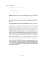
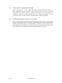
This Product is designed, developed and manufactured as contemplated for general use, including
without limitation, general office use, personal use and household use, but is not designed,
developed and manufactured as contemplated for use accompanying fatal risks or dangers that,
unless extremely high safety is secured, could lead directly to death, personal injury, severe
physical damage or other loss (hereinafter “High Safety Required Use”), including without
limitation, nuclear power core control, airplane control, air traffic control, mass transport operation
control, life support, weapon launching control. You shall not use this Product without securing the
sufficient safety required for the High Safety Required Use. If you wish to use this Product for
High Safety Required Use, please consult with our sale person in charge before such use
The contents of this manual is subject to change without prior notice.
All Rights Reserved. Copyright ¤ 2001 FUJITSU LIMITED
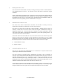
FOR SAFE OPERATION
Handling of This manual
This manual contains important information for using this product. Read thoroughly before using
the product. Use this product only after thoroughly reading and understanding especially the
section “Important Alert Items” in this manual. Keep this manual handy, and keep it carefully.
FUJITSU makes every effort to prevent users and bystanders from being injured or from suffering
damage to their property. Use the product according to this manual.
(Proceed to the Copyright Page)
C141-E124-01EN
i
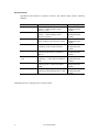
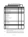
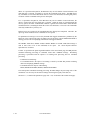
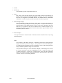
Related Standards
Specifications and functions of products covered by this manual comply with the following
standards.
Standard (Text) No.
ANSI X3. 131-1986
ANSI X3. 131-1994
X3T9.2/85-52 Rev 4.B
Name
American National Standard for Information
Systems --- Small Computer System
Interface (SCSI)
American National Standard for Information
Systems --- Small Computer System
Interface-2 (SCSI-2)
COMMON COMMAND SET (CCS) of the
Small Computer System Interface (SCSI)
X3T9.2 855D Rev 12
WORKING DRAFT Information
Technology SCSI-3 Parallel Interface
T10/1236-D Rev 12
WORKING DRAFT Information
technology SCSI Primary Commands-2
(SPC-2)
American National Standard for Information
Technology --- SCSI-3 Block Commands
(SBC)
WORKING DRAFT Information
technology SCSI-3 Architecture Model
(SAM)
WORKING DRAFT Information
technology SCSI Parallel Interface-3 (SPI3)
ANSI NCITS 306199x
X3T10/994D Rev 18
T10/1302D Rev 11
All Rights Reserved, Copyright ¤ 2001 Fujitsu, Limited
ii
C141-E124-01EN
Enacting Organization
American National
Standards Institute
(ANSI)
American National
Standards Institute
(ANSI)
American National
Standards Institute
(ANSI)
American National
Standards Institute
(ANSI)
American National
Standards Institute
(ANSI)
American National
Standards Institute
(ANSI)
American National
Standards Institute
(ANSI)
American National
Standards Institute
(ANSI)
REVISION RECORD
Edition
Date
published
01
March, 2001
Revised contents
Specification No.: C141-E124-**EN
C141-E124-01EN
iii
PREFACE
This manual explains concerning the MAH3182/MAH3091, MAK3728 and MAJ3364/MAJ3182/
MAJ3091 series 3.5 inch hard disk drives with internal SCSI controller.
The purpose of this manual is to provide specifications of each command and detailed explanations
of their functions for use of these magnetic disk drives incorporated into user systems, and to
present the information necessary for creating host system software. This manual is written for
users who have a basic knowledge of hard disk drives and their use in computer systems.
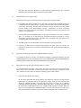
The composition of manuals related to these disk drives and the range of subjects covered in this
manual are shown in “Manual Organization,” provided on a subsequent page. Please use these
other manuals along with this manual as necessary.
Remark:
Product development of MAK3728 described in this manual has been discontinued.
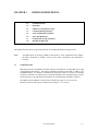
Composition and Contents of This Manual
This manual is composed of the 6 chapters shown below, a glossary and a list of abbreviations.
Chapter 1 Command Processing
This chapter describes the basic logical specifications related to SCSI command processing in the
disk drives.
Chapter 2 Data Buffer Management
This chapter describes the data buffer configuration provided in the disk drives and concerning
data transfer processing functions and cache operation.
Chapter 3 Command Specifications
This chapter describes specifications of SCSI commands provided by the disk drives and how to
use them.
Chapter 4 Parameter Data Formats
This chapter describes the parameter data formats provided by the disk drives and how to use
them.
Chapter 5 Sense Data and Error Recovery Methods
This chapter describes the configuration and contents of sense data which report to the host system
when an error occurs, etc., key information necessary for error recovery, recommended procedures
for error recovery to be executed through host system software and retry processing executed
internally in the disk drives for recovery
iv
C141-E124-01EN
Chapter 6 Disk Media Management
This chapter describes the procedure for initializing the disk media, methods of treating media
defects and data recovery methods for the disk drives.
Glossary
The glossary explains technical terms which are necessary to the reader’s understanding when
reading this manual.
List of Abbreviations
This list shows the full spelling of abbreviations used in this manual.
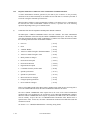
The model name of disk drives covered by this manual differs in its ending suffix (Note 1)
depending on its device type (3 types), the electrical conditions of the SCSI interface used to
connect the disk drive to the host system and its capacity and data format at the time it was
shipped, but in this manual, except in cases where models need to be especially distinguished, a
representative model name (Note 2) is used. In addition, these disk drives are called Intelligent
Disk Drive (IDD), “drive” or “device” in this manual.
Note 1:
Model Name
M AH 3 182 MC
Interface type
MP: Low voltage differential 16-bit SCSI Ultra-160/m
MC: Low voltage differential 16-bit SCSI Ultra-160/m
SCA2 connector
Formatted capacity (100 MB units)
Disk size
Type
AH: 1-inch height (7,200 rpm)
AK: Full-height (10,025 rpm)
AJ: 1-inch height (10,025 rpm)
C141-E124-01EN
v
Note 2:
Typical model name
Type model name
MAH3182
MAH3091
MAK3728
MAJ3364
MAJ3182
MAJ3091
Model name
MAH3182MP, MAH3182MC
MAH3091MP, MAH3091MC
MAK3728MP, MAK3728MC
MAJ3364MP, MAJ3364MC
MAJ3182MP, MAJ3182MC
MAJ3091MP, MAJ3091MC
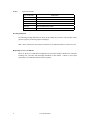
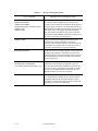
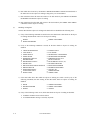
Warning Indications
The following warning indications are shown in this manual to prevent the user and other nearby
persons or property from being injured or damaged.
Note “Note” indicates the most effective method of use or information that is of value to the user.
Requesting for User’s Comments
Please use the User’s Comment Form attached to the end of this manual to identify user comments
including error, inaccurate and misleading information of this manual. Contact to your Fujitsu
representative for additional comment forms if required.
vi
C141-E124-01EN
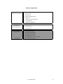
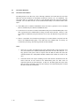
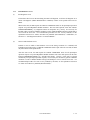
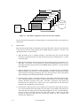
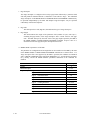
Manual Organization
Product/
Maintenance Manual
SCSI Physical
Interface Specifications
SCSI Logical Interface
Specifications
(This Manual)
1.
2.
3.
4.
5.
6.
7.
8.
General Description
Specifications
Data Format
Installation Requirements
Installation
Diagnostics and Maintenance
Error Analysis
Principle of Operation
1. SCSI Bus
2. SCSI Messages
3. Error Recovery
1.
2.
3.
4.
5.
6.
Command Processing
Data Buffer Management
Command Specifications
Parameter Data Formats
Sense Data Error Recovery Methods
Disk Media Management
C141-E124-01EN
vii
CONTENTS
page
CHAPTER 1 COMMAND PROCESSING .................................................................................. 1-1
1.1
Command Format ......................................................................................................... 1-1
1.2
Status Byte .................................................................................................................... 1-7
1.3
Outline of Command Processing................................................................................... 1-10
1.3.1
Single commands .......................................................................................................... 1-10
1.3.2
Command link............................................................................................................... 1-11
1.3.3
Disconnect/reconnect processing .................................................................................. 1-13
1.3.4
Synchronous mode data transfer/wide mode data transfer ............................................ 1-17
1.4
Command Queuing Function ........................................................................................ 1-19
1.4.1
Untagged queuing ......................................................................................................... 1-19
1.4.2
Tagged queuing............................................................................................................. 1-21
1.5
UNIT ATTENTION Condition .................................................................................... 1-23
1.5.1
Generation of the UNIT ATTENTION condition ........................................................ 1-23
1.5.2
Response and Release Condition at UNIT ATTENTION Condition Hold State.......... 1-24
1.5.3
UNIT ATTENTION condition multiple hold ............................................................... 1-25
1.6
Sense Data Hold State................................................................................................... 1-26
1.6.1
Sense data hold condition ............................................................................................. 1-26
1.6.2
Response and release conditions at sense data hold state ............................................. 1-27
1.7
Command Processing Exceptions ................................................................................. 1-28
1.7.1
Overlapping commands ................................................................................................ 1-28
1.7.2
Illegal LUN specification.............................................................................................. 1-29
1.7.3
Reserved operation code............................................................................................... 1-29
1.7.4
Command processing in the not ready state .................................................................. 1-29
1.7.5
Error recovery processing ............................................................................................. 1-31
1.7.6
Reset processing ........................................................................................................... 1-33
1.7.7
Fatal hardware errors .................................................................................................... 1-35
1.8
Data Block Addressing ................................................................................................. 1-36
1.8.1
Definition of data space ................................................................................................ 1-36
1.8.2
Logical block addressing .............................................................................................. 1-38
CHAPTER 2 DATA BUFFER MANAGEMENT ........................................................................ 2-1
2.1
Data Buffer ................................................................................................................... 2-1
2.1.1
Data buffer configuration and basic operation.............................................................. 2-1
C141-E124-01EN
ix
2.1.2
Operation mode setting ................................................................................................. 2-5
2.2
Look-Ahead Cache Feature .......................................................................................... 2-7
2.2.1
Caching operation ......................................................................................................... 2-7
2.2.2
Caching parameters....................................................................................................... 2-9
2.2.3
Look-Ahead operation, Look-Ahead volume................................................................ 2-10
2.3
Write Cache .................................................................................................................. 2-11
CHAPTER 3 COMMAND SPECIFICATIONS........................................................................... 3-1
3.1
Control/Sense Commands............................................................................................. 3-1
3.1.1
TEST UNIT READY (00) ............................................................................................ 3-1
3.1.2
INQUIRY (12)..............................................................................................................3-2
3.1.3
READ CAPACITY (25) ............................................................................................... 3-14
3.1.4
CHANGE DEFINITION (40)....................................................................................... 3-16
3.1.5
MODE SELECT (15) ................................................................................................... 3-21
3.1.6
MODE SELECT EXTENDED (55) ............................................................................. 3-30
3.1.7
MODE SENSE (1A) ..................................................................................................... 3-32
3.1.8
MODE SENSE EXTENDED (5A) ............................................................................... 3-38
3.1.9
REZERO UNIT (01)..................................................................................................... 3-40
3.1.10
START/STOP UNIT (1B)............................................................................................ 3-41
3.1.11
RESERVE (16) ............................................................................................................. 3-43
3.1.12
RESERVE EXTENDED (56) ...................................................................................... 3-47
3.1.13
RELEASE (17) ............................................................................................................. 3-48
3.1.14
RELEASE EXTENDED (57) ...................................................................................... 3-49
3.1.15
REQUEST SENSE (03)................................................................................................ 3-50
3.1.16
LOG SELECT (4C) ...................................................................................................... 3-52
3.1.17
LOG SENSE (4D) ........................................................................................................ 3-56
3.1.18
PERSISTENT RESERVE IN (5E) ............................................................................... 3-58
3.1.18.1
PERSISTENT RESERVE IN service actions ............................................................... 3-58
3.1.18.1.1
READ KEYS ................................................................................................................ 3-59
3.1.18.1.2
READ RESERVATIONS............................................................................................. 3-59
3.1.18.2
PERSISTENT RESERVE IN parameter data for READ KEYS .................................. 3-59
3.1.18.3
PERSISTENT RESERVE IN parameter data for READ RESERVATION ................. 3-61
3.1.18.3.1
Persistent reservations scope......................................................................................... 3-63
3.1.18.3.1.1 Logical unit scope......................................................................................................... 3-63
3.1.18.3.1.2 Element scope (not supported)...................................................................................... 3-63
3.1.18.3.2
Persistent reservations type........................................................................................... 3-63
3.1.19
PERSISTENT RESERVE OUT (5F)............................................................................ 3-65
x
C141-E124-01EN
3.1.19.1
PERSISTENT RESERVE OUT service actions ........................................................... 3-66
3.1.19.2
PERSISTENT RESERVE OUT parameter list............................................................. 3-67
3.1.20
REPORT LUNS (A0) ................................................................................................... 3-69
3.1.21
REPORT DEVICE IDENTIFIER (A3) ........................................................................ 3-71
3.1.22
SET DEVICE IDENTIFIER (A4) ................................................................................ 3-73
3.2
Data Access Commands................................................................................................ 3-75
3.2.1
READ (08).................................................................................................................... 3-75
3.2.2
READ EXTENDED (28).............................................................................................. 3-76
3.2.3
WRITE (0A) ................................................................................................................. 3-77
3.2.4
WRITE EXTENDED (2A) ........................................................................................... 3-78
3.2.5
WRITE AND VERIFY (2E)......................................................................................... 3-79
3.2.6
VERIFY (2F) ................................................................................................................ 3-80
3.2.7
SEEK (0B) .................................................................................................................... 3-81
3.2.8
SEEK EXTENDED (2B) .............................................................................................. 3-82
3.2.9
SET LIMITS (33) (Not Supported) .............................................................................. 3-83
3.2.10
SYNCHRONIZE CACHE (35) .................................................................................... 3-86
3.3
Format Commands........................................................................................................ 3-87
3.3.1
FORMAT UNIT (04) ................................................................................................... 3-87
3.3.2
REASSIGN BLOCKS (07)........................................................................................... 3-98
3.3.3
READ DEFECT DATA (37) ........................................................................................ 3-102
3.4
Maintenance, Diagnostic Commands............................................................................ 3-107
3.4.1
SEND DIAGNOSTIC (1D) .......................................................................................... 3-107
3.4.2
RECEIVE DIAGNOSTIC RESULTS (1C) .................................................................. 3-114
3.4.3
WRITE BUFFER (3B) ................................................................................................. 3-118
3.4.4
READ BUFFER (3C) ................................................................................................... 3-124
3.4.5
READ LONG (3E) ....................................................................................................... 3-129
3.4.6
WRITE LONG (3F)...................................................................................................... 3-131
3.4.7
WRITE SAME (41) ...................................................................................................... 3-133
CHAPTER 4 PARAMETER DATA FORMATS......................................................................... 4-1
4.1
Mode Parameters .......................................................................................................... 4-1
4.1.1
Read/Write error recovery parameters (page code = 1) ................................................ 4-1
4.1.2
Disconnect/reconnect parameters (page code = 2)........................................................ 4-11
4.1.3
Format parameter (page code = 3) ................................................................................ 4-15
4.1.4
Drive parameter (page code = 4) .................................................................................. 4-19
4.1.5
Verify error recovery parameters (page code = 7) ....................................................... 4-21
4.1.6
Caching parameters (page code = 8)............................................................................. 4-23
C141-E124-01EN
xi
4.1.7
Control mode parameters (page code = 0A) ................................................................ 4-29
4.1.8
Notch parameter (page code = 0C) ............................................................................... 4-33
4.1.9
Informational exceptions control page (page code = 1C) ............................................. 4-35
4.1.10
Additional error recovery parameters (page code = 21) ............................................... 4-39
4.2
Log Parameters ............................................................................................................. 4-40
4.2.1
Supprot log page (X'00') ............................................................................................... 4-40
4.2.2
Buffer overrun / underrun page (X'01')......................................................................... 4-41
4.2.3
Write error count page (X'02') ...................................................................................... 4-43
4.2.3.1
Write errors recovered without delays (Page 02, Code 0000) ...................................... 4-43
4.2.3.2
Write errors recovered with possible delays (Page 02, Code 0001) ............................. 4-44
4.2.3.3
Total posted write errors (Page 02, Code 0002) ........................................................... 4-44
4.2.3.4
Total posted recoverable write errors (Page 02, Code 0003)........................................ 4-45
4.2.3.5
Total write bytes processed (Page 02, Code 0005) ....................................................... 4-45
4.2.3.6
Total posted unrecoverable write errors (Page 02, Code 0006).................................... 4-46
4.2.4
Read error count page (X'03') ....................................................................................... 4-46
4.2.4.1
Read errors recovered without delays (Page 03, Code 0000) ....................................... 4-47
4.2.4.2
Read errors recovered with possible delays (Page 03, Code 0001) .............................. 4-47
4.2.4.3
Total posted read errors (Page 03, Code 0002) ............................................................ 4-48
4.2.4.4
Total posted recoverable read errors (Page 03, Code 0003)......................................... 4-48
4.2.4.5
Total read bytes processed (Page 03, Code 0005) ........................................................ 4-49
4.2.4.6
Total posted unrecoverable read errors (Page 03, Code 0006) ..................................... 4-49
4.2.5
Verify error count page (X'05') ..................................................................................... 4-50
4.2.5.1
Verify errors recovered without delays (Page 05, Code 0000) ..................................... 4-50
4.2.5.2
Vefiry errors recovered with possible delays (Page 05, Code 0001) ............................ 4-51
4.2.5.3
Total posted verify errors (Page 05, Code 0002) .......................................................... 4-51
4.2.5.4
Total posted recoverable verify errors (Page 05, Code 0003) ...................................... 4-52
4.2.5.5
Total verify bytes processed (Page 05, Code 0005)...................................................... 4-52
4.2.5.6
Total posted unrecoverable verify errors (Page 05, Code 0006) .................................. 4-53
4.2.6
Non-medium error count page (X'06') .......................................................................... 4-53
4.2.7
Temperature page (X'0D')............................................................................................. 4-54
4.2.7.1
Temperature (Page 0D, Code 0000) ............................................................................. 4-54
4.2.7.2
Reference temperature (Page 0D, Code 0001).............................................................. 4-55
4.2.8
Start-stop cycle counter page (X'0E')............................................................................ 4-55
4.2.8.1
Date of manufacture (Page 0E, Code 0001).................................................................. 4-56
4.2.8.2
Accounting date (Page 0E, Code 0002) ........................................................................ 4-57
4.2.8.3
Specified cycle count over device lifetime (Page 0E, Code 0003) ............................... 4-57
4.2.8.4
Start-stop cycle counter (Page 0E, Code 0004) ............................................................ 4-58
xii
C141-E124-01EN
4.2.9
Application client page (X'0F') ..................................................................................... 4-58
4.2.9.1
General usage application client parameter data (Page 0F, Code 0000-003F) ............. 4-59
4.2.10
Self-test result page (X'10') ........................................................................................... 4-59
4.2.10.1
Self-test result parameter data (Page 10, Code 0001-0014).......................................... 4-60
4.2.11
SMART status page (X'2F') .......................................................................................... 4-61
4.2.12
SMART data page (X'38')............................................................................................. 4-61
CHAPTER 5 SENSE DATA ERROR RECOVERY METHODS .............................................. 5-1
5.1
Sense Data .................................................................................................................... 5-1
5.1.1
Sense data format.......................................................................................................... 5-1
5.1.2
Sense data basic information......................................................................................... 5-3
5.1.3
Sense data additional information................................................................................. 5-11
5.2
INIT Error Recovery Methods (Recommended) .......................................................... 5-12
5.2.1
Termination status analysis and error recovery methods .............................................. 5-12
5.2.2
Sense data analysis and error recovery methods ........................................................... 5-15
5.2.3
Error logging................................................................................................................. 5-23
5.3
Disk Drive Error Recovery Processing ......................................................................... 5-24
5.3.1
Error states and retry processing procedures ................................................................ 5-24
5.3.2
Auto alternate block allocation processing ................................................................... 5-25
5.3.3
Error recovery processing control................................................................................. 5-27
CHAPTER 6 DISK MEDIA MANAGEMENT ............................................................................ 6-1
6.1
Defect Management ...................................................................................................... 6-1
6.2
Disk Media Initialization .............................................................................................. 6-4
6.2.1
Initialization during installation .................................................................................... 6-4
6.2.2
Re-initialization ............................................................................................................ 6-5
6.3
Data Block Verification Methods (Recommended) ...................................................... 6-7
6.4
Alternate Block Allocation Processing ......................................................................... 6-9
GLOSSARY....................................................................................................................................... GL - 1
ABBREVIATIONS ........................................................................................................................... AB - 1
C141-E124-01EN
xiii
FIGURES
Pages
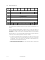
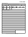
1.1
6-Byte CDB Basic Format ....................................................................................................... 1-2
1.2
10-Byte CDB Basic Format ..................................................................................................... 1-2
1.3
12-Byte CDB Basic Format ..................................................................................................... 1-3
1.4
Status Byte ............................................................................................................................... 1-7
1.5
Data space configuration.......................................................................................................... 1-37
2.1
Data buffer configuration (in the case of 8 cache segments)................................................... 2-2
2.2
Example of data buffer operation during read.......................................................................... 2-3
2.3
Example of data buffer operation during write......................................................................... 2-4
2.4
Parameters for controlling reconnection timing ....................................................................... 2-5
2.5
Cache control parameters ......................................................................................................... 2-9
3.1
Standard INQUIRY data .......................................................................................................... 3-4
3.2
Command support data............................................................................................................. 3-9
3.3
VPD information: VPD identifier list...................................................................................... 3-11
3.4
VPD information: device serial No. ........................................................................................ 3-12
3.5
VPD information: operation mode .......................................................................................... 3-13
3.6
READ CAPACITY data .......................................................................................................... 3-15
3.7
MODE SELECT parameter structure....................................................................................... 3-23
3.8
MODE SELECT command (Group 0) parameter configuration .............................................. 3-25
3.9
MODE SELECT EXTENDED command (Group 2) parameter configuration........................ 3-31
3.10
MODE SENSE command (Group 0) parameter configuration ................................................ 3-35
3.11
MODE SENSE EXTENDED command (Group 2) parameter configuration .......................... 3-39
3.12
SET LIMITS command: Specifying the range where access is permitted............................... 3-84
3.13
FORMAT UNIT command parameter list configuration ......................................................... 3-90
3.14
Defect descriptor: Byte distance from index format................................................................ 3-93
3.15
Defect descriptor: physical sector address format................................................................... 3-94
3.16
REASSIGN BLOCK command: defect data list configuration............................................... 3-99
3.17
READ DEFECT DATA command: Defect data configuration............................................... 3-103
3.18
SEND DIAGNOSTIC command: parameter list configuration .............................................. 3-110
3.19
SEND DIAGNOSTIC parameters: page code list................................................................... 3-111
3.20
SEND DIAGNOSTIC parameters: logical/physical address conversion ................................ 3-111
3.21
RECEIVE DIAGNOSTIC RESULTS command: Response data configuration ..................... 3-115
3.22
RECEIVE DIAGNOSTIC RESULTS response data: page code list ...................................... 3-116
3.23
RECEIVE DIAGNOSTIC RESULTS response data: logical/physical address conversion.... 3-116
3.24
WRITE BUFFER command: buffer data (Mode = 000, 001) ................................................. 3-119
3.25
READ BUFFER command: buffer data (Mode = 0000, 0001)............................................... 3-125
3.26
READ BUFFER command: buffer descriptor.......................................................................... 3-127
3.27
READ BUFFER command: Echo buffer descriptor................................................................. 3-128
xiv
C141-E124-01EN
4.1
MODE SELECT parameters: read/write error recovery parameters ........................................ 4-2
4.2
MODE SELECT parameters: disconnect/reconnect parameters .............................................. 4-11
4.3
MODE SELECT parameters: format parameters .................................................................... 4-15
4.4
MODE SELECT parameters: drive parameters ...................................................................... 4-19
4.5
MODE SELECT parameters: verify error recovery parameters.............................................. 4-21
4.6
MODE SELECT parameters: caching parameters ................................................................... 4-23
4.7
MODE SELECT parameters: control mode parameters........................................................... 4-29
4.8
MODE SELECT parameters: informal exception control page .............................................. 4-35
4.9
MODE SELECT parameters: additional error recovery parameters ....................................... 4-39
5.1
Expanded sense data format ..................................................................................................... 5-2
5.2
Sense key inherent information ................................................................................................ 5-4
5.3
Analysis of the termination status............................................................................................. 5-13
TABLES
1.1
Responses to Link Specification Commands............................................................................ 1-12
1.2
Types of Command and Disconnect Processing ...................................................................... 1-14
1.3
Sense data in not ready state .................................................................................................... 1-30
1.4
Outline of SCSI Bus Error Recovery Processing ..................................................................... 1-31
1.5
Outline of disk drive error recovery processing ....................................................................... 1-32
1.6
Reset processing during write .................................................................................................. 1-34
3.1
MODE SENSE Data Type Specifications................................................................................ 3-34
3.2
Persistent reservations type codes ............................................................................................ 3-64
3.3
PERSISTENT RESERVE OUT service action codes.............................................................. 3-66
3.4
PERSISTENT RESERVE OUT service action and valid parameters...................................... 3-68
3.5
FORMAT UNIT command defect processing ......................................................................... 3-96
3.6
Error recovery control flags during the self-diagnosis test....................................................... 3-108
4.1
Combination of error recovery flags ........................................................................................ 4-7
5.1
Sense key.................................................................................................................................. 5-5
5.2
Sense and subsense codes ........................................................................................................ 5-6
5.3
Sense data error classification .................................................................................................. 5-16
5.4
Error recovery processing procedures...................................................................................... 5-19
5.5
Disk drive errors and number of retries.................................................................................... 5-28
C141-E124-01EN
xv
CHAPTER 1
COMMAND PROCESSING
1.1
Command Format
1.2
Status Byte
1.3
Outline of Command Processing
1.4
Command Queuing Function
1.5
UNIT ATTENTION Condition
1.6
Sense Data Hold State
1.7
Command Processing Exceptions
1.8
Data Block Addressing
This chapter describes the basic logical specifications of the IDD command processing functions.
Note:
1.1
The IDD operates as the target (TARG) on the SCSI bus. In the explanations in this chapter,
the IDD is mentioned as “TARG”, except in cases where a particularly clear distinction is
necessary.
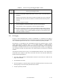
Command Format
Input/output operation commands from INIT (initiator) to the IDD are accomplished by the CDB
(Command Descriptor Block). The CDB is information transferred from INIT to TARG in the
COMMAND phase. In a number of commands, the parameters which are necessary for command
execution in the DATA OUT phase may be specified in addition to the CDB specification. Details
concerning these are described in the specifications for each individual command in Chapter 3.
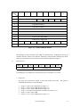
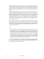
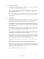
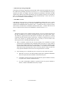
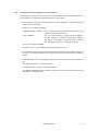
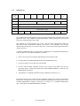
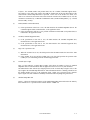
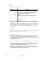
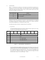
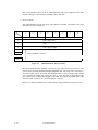
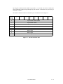
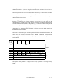
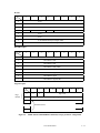
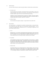
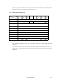
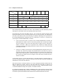
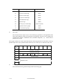
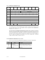
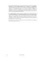
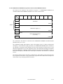
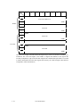
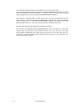
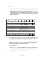
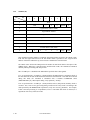
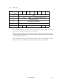
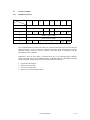
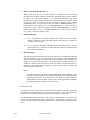
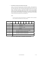
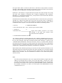
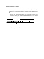
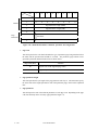
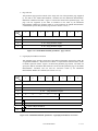
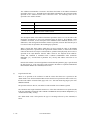
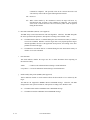
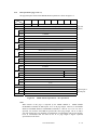
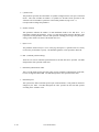
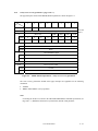
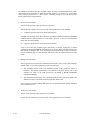
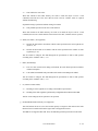
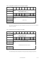
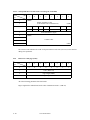
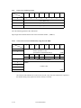
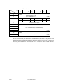
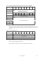
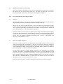
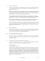
The CDB used by the IDD has 3 formats, these formats have length of 6, 10 and 12 bytes.
The basic format of each respective CDB is shown in Figures 1.1, 1.2 and 1.3.
C141-E124-01EN
1-1
Bit
Byte
7
6
5
0
3
LUN
Logical Block Address
3
Logical Block Address (LSB)
4
Transfer Data Length
5
Control Byte
Figure 1.1
Bit
7
6
5
0
0
6-Byte CDB Basic Format
4
3
2
1
0
0
0
0
0
0
0
Operation Code
1
LUN
0
0
2
Logical Block Address (MSB)
3
Logical Block Address
4
Logical Block Address
5
Logical Block Address (LSB)
6
1
Logical Block Address (MSB)
2
Byte
2
Operation Code
1
0
0
0
0
0
7
Transfer Data Length (MSB)
8
Transfer Data Length (LSB)
9
Control Byte
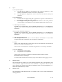
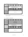
Figure 1.2
1-2
4
10-Byte CDB Basic Format
C141-E124-01EN
Bit
7
Byte
6
5
4
0
3
2
1
0
0
0
0
0
0
0
Operation Code
1
LUN
0
0
2
Logical Block Address (MSB)
3
Logical Block Address
4
Logical Block Address
5
Logical Block Address (LSB)
6
Transfer Data Length (MSB)
7
Transfer Data Length (LSB)
8
Transfer Data Length (MSB)
9
Transfer Data Length (LSB)
10
0
0
0
11
0
0
Control Byte
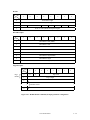
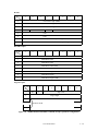
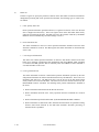
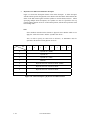
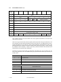
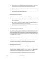
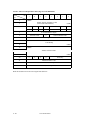
Figure 1.3
12-Byte CDB Basic Format
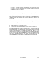
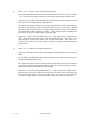
The meanings of each of the fields in the CDB are explained below. Depending on the type of
command, the basic format of the CDB, the definitions of fields and their meanings may differ.
Details are described in the specifications for each individual command in Chapter 3.
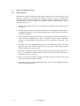
(1)
Operation code
Bit 7
6
5
Group Code
4
3
2
1
0
Command Code
The leading byte of all CDBs shows the format and type of command to be executed.
a. Group code
The group code specifies the number of bytes and format of the CDB.
commands shown below are used in the IDD.
x
x
x
x
x
x
Group 0
Group 1
Group 2
Group 3
Group 4
Group 5
The groups of
(“000”):6-byte CDB (Shown in Figure 1.1)
(“001”):10-byte CDB (Shown in Figure 1.2)
(“010”):10-byte CDB (Shown in Figure 1.2)
("011"):Reserved Operation Code (Shown in Section 1.7.3.)
("100"):16-byte CDB
("101"):12-byte CDB (Shown in Figure 1.3)
C141-E124-01EN
1-3
b. Command code
Command code specifies the type of command in each group.
(2)
LUN (Logical Unit Number)
This field specifies the address of the logical unit (device) connected under the TARG in cases
where the IDENTIFY message is not used. If the IDENTIFY message is used, the value of the
CDB’s LUN field is ignored when the LUN is specified.
Note:
It is possible that the definition of this field may be changed in future SCSI standards. It is
recommended that the LUN be specified using the IDENTIFY message, and that a zero be
specified in this CDB field.
(3)
Logical block address
This field shows the leading logical data block address of the data block on the disk media to be
processed by the command. In the group 0 CDB, 21-bit block addressing is possible and in the
group 1, group 2 and group 5 CDBs, 32-bit block addressing is possible. Specifications for logical
data block addressing in the IDD are described in Section 1.8.
(4)
Transfer data length
In this field, the length of data to be transferred between INIT and TARG when the command is
executed is specified by the number of logical data blocks or the number of bytes. In subsequent
descriptions, the former is called the “transfer block count” and the latter is called the “transfer
byte length” or “parameter list length.”
Furthermore, this field may be used with a different meaning, or it may not have any meaning at
all, depending on the type of command. There are also some commands which allocate 3 or more
bytes as the transfer data length field. Detailed specifications of these commands are described in
the individual command specifications in Chapter 3.
a. Transfer block count
When the “Transfer Data Length” is specified as the “Transfer Block Count,” this field
specifies the number of logical data blocks to be transferred between INIT and the IDD.
In commands where this field is 1 byte in length, if the field’s specified value is 0, it is
regarded as specifying 256 blocks, and it is possible to specify a block count ranging from 1 to
256 blocks. On the other hand, in commands where this field is 2 bytes in length, if the field’s
specified value is 0, no data transfer is executed. It is possible to specify a block count ranging
from 0 to 65,535 blocks.
1-4
C141-E124-01EN
b. Transfer byte length or parameter list length
When this field is specified as the “Transfer Byte Length” or “Parameter List Length,” that
command specifies data length to be transferred between the INIT and the IDD, expressed as
the number of bytes. When 0 is specified in this field, data transfer is not executed, except in
cases where it is expressly stated in the individual command specifications in Chapter 3.
In commands which send parameters necessary for executing a command from the INIT to the
IDD, this field is called the “Parameter List Length,” and it specifies the total number of types
in the parameter list which the INIT is sending.
On the other hand, in commands for receiving information from the IDD (REQUEST SENSE,
INQUIRY, etc.), this field is called the “Transfer Byte Length,” and specifies the maximum
number of bytes which the INIT can receive (the number of bytes of area secured within the
INIT for receiving information). The IDD transfers either the number of effective bytes of the
type of information specified in the command, or the value specified in the “Transfer Byte
Length” field, whichever is the smallest number of bytes, and only that number, to the INIT.
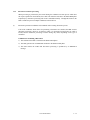
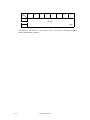
(5)
Control byte
Bit 7
6
5
4
3
2
1
0
0
0
0
0
0
0
0
Link
a. Link
Command link is specified by this bit is “1.” Details of the operation of the command link are
described in Section 1.3.2.
b. Bit 7, 6 (vendor unique)
Except in cases where it is expressly specified in the individual commands, specification of
these bits has no meaning, and the IDD disregards the specified values.
C141-E124-01EN
1-5
Note:
It is possible that bits 7 and 6 of the control byte will be used in future product
specifications as an inherent control field. It is recommended that zeros be specified in
this field.
(6)
Handling an illegal CDB
If there is an error in the contents of a description (specification) in the CDB, or if there is an error
in the specifications in parameters transferred from the INIT by CDB specifying, that command
ends with a CHECK CONDITION status. In the case of a command to change the data on the
disk media, when there is an error in the CDB’s specifications, the disk media is not changed by
that command. But when there is an error in the parameters transferred in the DATA OUT phase,
the contents of the disk media in the range specified by the command may be changed. Also, even
in cases where there is an error in the CDB’s specifications in a command accompanying the
DATA OUT phase, the DATA OUT phase is executed after the COMMAND phase is terminated,
but those data are not used. For example, if there is an error in the CDB specification of a WRITE
command, the IDD executes the transfers several bytes of data (the data length to be transferred is
not specified), but those data are not written to the disk media. Details are described in the
individual command specifications in Chapter 3.
If there is an error in the CDB specification in a command which executes disconnect processing
(shown in Section 1.3.3), the disconnect processing may be executed after the COMMAND phase
is terminated. In this case, reconnect processing is executed afterward and the status (CHECK
CONDITION) is reported.
Note:
If a CDB with an undefined group code (group 3, 4) is specified, the IDD requests transfer of
10 bytes in the COMMAND phase. After that has been received, the status (CHECK
CONDITION) is reported.
1-6
C141-E124-01EN
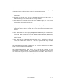
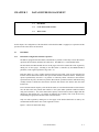
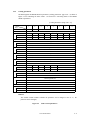
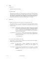
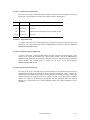
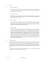
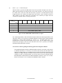
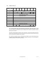
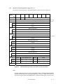
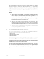
1.2
Status Byte
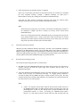
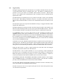
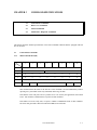
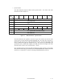
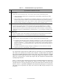
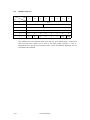
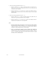
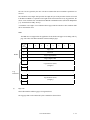
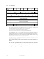
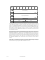
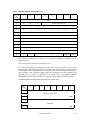
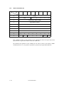
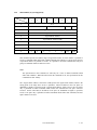
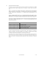
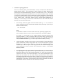
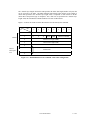
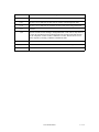
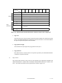
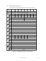
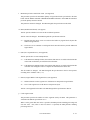
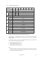
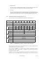
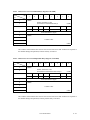
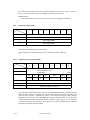
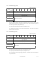
Figure 1.4 shows status byte format and the type of status that the IDD supports.
The status byte is one byte of information sent from the TARG to the INIT in the STATUS phase
when one command is completed, and notifies the INIT of the results of the command’s execution.
The status byte is also sent even in cases when the TARG is in a state which it makes it impossible
for it to execute the command when it receives a request for an input/output operation. However, if
the command is cleared by switching to the BUS FREE phase forcibly through an ABORT TASK
SET message, an ABORT TASK message, a CLEAR TASK SET message, a TARGET RESET
message, a RESET condition or a SCSI bus error state, etc., the status byte for that command is not
reported.
After the TARG reports the status byte in the STATUS phase, it will always send a TASK
COMPLETE message or a LINKED TASK COMPLETE (WITH FLAG) message to notify the
INIT of the validity of the status byte.
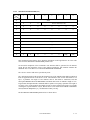
Bit 7
6
0
0
Bit
5
4
3
2
1
Status Byte Code
0
0
5 4 3 2 1
0 0 0 0 0
GOOD Status
0 0 0 0 1
CHECK CONDITION Status
0 0 0 1 0
CONDITION MET Status
0 0 1 0 0
BUSY Status
0 1 0 0 0
INTERMEDIATE Status
0 1 0 1 0
INTERMEDIATE CONDITION MET Status
0 1 1 0 0
RESERVATION CONFLICT Status
1 0 0 0 1
COMMAND TERMINATED Status
1 0 1 0 0
QUEUE FULL Status
Figure 1.4
Status Byte
C141-E124-01EN
1-7
(1)
GOOD status
This status indicates that execution of the command ended normally.
(2)
CHECK CONDITION status
This status is reported in the following cases a) to c). The IDD generates sense data when it
reports this status and indicates the detailed cause. The INIT issues a REQUEST SENSE
command when it receives this status and should sample sense data.
a) If the sense key of the sense data indicates RECOVERED ERROR [=1], the last command,
which is the last command, indicates that it ended normally with the error recovery processing
executed by the IDD.
b) If the sense key of the sense data indicates UNIT ATTENTION [=6], it indicates that the IDD
was holding the UNIT ATTENTION condition. Details of the UNIT ATTENTION condition
are described in Section 1.5.
c) In cases other than the above, it indicates that command execution is impossible, or that
command execution was terminated abnormally.
(3)
CONDITION MET Status
This status is reported when it is possible to secure the cache memory area necessary for reading all the
logical data blocks specified in the PRE-FETCH command (in the case of “Immed = 1”), or when
reading of all the specified logical data blocks is completed (in the case of “Immed = 0”).
The IDD does not support the PRE-FETCH command. Therefore, this status is not reported.
(4)
BUSY status
This status indicates that the IDD is in the busy state and it cannot receive a new command.
Normally, an INIT that receives this status reissues the original command after waiting an
appropriate period of time.
The IDD reports the BUSY status in the following cases (the command stack function is explained
in Section 1.4).
a) If the IDD receives a new command while it is executing or is queuing command (except a
command without executing disconnect processing as shown in Section 1.3.3) but the INIT
which issued that command does not satisfy the disconnect enable conditions.
b) If the IDD receives a command without executing disconnect processing (as shown in Section
1.3.3) while it is executing or is queuing command.
c) If the DISCONNECT message for command queuing has been rejected by the INIT while the
IDD is executing or queuing command.
d) If a command with executing untagged disconnect processing is received while the command
queue is full.
1-8
C141-E124-01EN
(5)
INTERMEDIATE status
This status indicates that a command which specifies a link (except the last command in a group of
linked commands with “1” as its Link bit) has been completed normally. If a command which
specifies a link is completed abnormally and the CHECK CONDITION status or RESERVATION
CONFLICT status is reported, the command link is broken an the subsequent linked commands are
not executed.
(6)
INTERMEDIATE CONDITION MET Status
This status is reported when it is possible to secure the cache memory area necessary to read all the
logical data blocks specified in a PRE-FETCH command which specifies a link (in the case of
“Immed = 1”), or when reading of all the specified logical data blocks is completed (in the case of
“Immed = 0”).
The IDD does not support the PRE-FETCH command. Therefore, this status is not reported.
(7)
RESERVATION CONFLICT status
This status indicates that the IDD is reserved by another INIT, and that use is impossible until the
reserved status is canceled. Normally, an INIT which receives this status reissues the original
command after waiting an appropriate period of time.
(8)
COMMAND TERMINATED status
This status is reported when the IDD has completed the executing input/output operation when it
received a TERMINATE I/O PROCESS message from the INIT.
(9)
QUEUE FULL status
This status is reported if the IDD cannot register a received tagged command in the command
queue because there is no empty space in the command queue.
C141-E124-01EN
1-9
1.3
Outline of Command Processing
1.3.1
Single commands
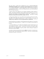
Following shows single command processing examples which are the most basic operations on the
SCSI bus. Furthermore, if disconnect processing is permitted, it may be accompanied by
disconnect/reconnect processing during the command execution, depending on the type of
command, but this operation is omitted in the following explanation. The disconnect function is
described in Section 1.3.3.
1) The INIT sets the initial values for the command in the command pointer, data pointer and
status pointer.
2) The INIT selects the TARG in the SELECTION phase after obtaining the SCSI bus usage in
the ARBITRATION phase. After the SELECTION phase is ended, the SCSI bus control is
entrusted to the TARG.
3) If the ATTENTION condition exists when the TARG responds to the SELECTION phase, the
TARG executes the MESSAGE OUT phase. Normally, the INIT sends the IDENTIFY
message as the initial message and specifies the device (LUN) that is the object of the
operation.
4) The TARG executes the COMMAND phase and receives the CDB from the INIT. The TARG
judges the length of the CDB by the group code in the first byte of the CDB and requests
transfer of the necessary number of bytes.
5) The TARG investigates the contents of the command and executes the requested operation. In
the case of commands for which data transfer on the SCSI bus is necessary, the DATA IN or
the DATA OUT phase is executed.
6) When execution of the command is completed, the TARG reports the execution results by the
status byte in the STATUS phase to the INIT.
7) The TARG reports the TASK COMPLETE message to the INIT in the MESSAGE IN phase
and enters the BUS FREE phase.
1 - 10
C141-E124-01EN
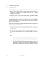
1.3.2
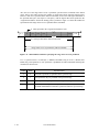
Command link
The command link function is a function which causes the TARG to execute continuous processing
of multiple commands. Following shows examples of command link processing.
1) The INIT sets the initial values for the command in the command pointer, data pointer and
status pointer.
2) Obtaining the SCSI bus usage, selection of the TARG and specification of the LUN by the
IDENTIFY message are the same as in the case of single command.
3) The TARG receives commands from the INIT in the COMMAND phase, but “1” is specified
in the Link bit of the control byte of the CDB.
4) The TARG analyzes the command and executes the requested processing.
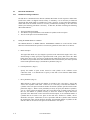
5) If processing of the command is completed normally, the TARG reports the INTERMEDIATE
status in the STATUS phase to the INIT. At this time, the command link function becomes
effective.
6) The TARG informs the INIT of the LINKED TASK COMPLETE or the LINKED TASK
COMPLETE WITH FLAG message, depending on the value of the Flag bit in the control byte
of the CDB. When the INIT has received the LINKED TASK COMPLETE (WITH FLAG)
message, the command, data and status pointers are updated to the initial values for the next
linked command.
7) The TARG enters the COMMAND phase immediately after the MESSAGE IN phase and
receives the command to be executed next. After that, it performs either single command
(Link bit = “0”) processing or command link (Link bit = “1”) processing.
The command link continues until a command with “0” specified in the Link bit of its CDB is
issued or until a command terminates abnormally.
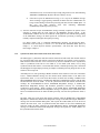
The command link function is made effective only in the case that commands with link
specifications are completed normally. If a command with a link specification is completed in an
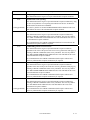
error state or in an exception state, the command link function is invalidated. Table 1.1 shows the
response of the IDD when commands with a Link specification are terminated.
C141-E124-01EN
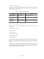
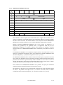
1 - 11
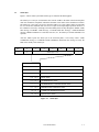
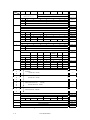
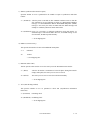
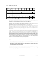
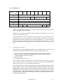
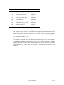
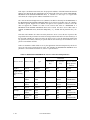
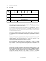
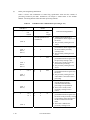
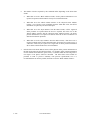
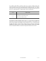
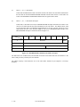
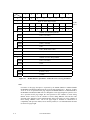
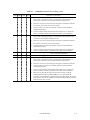
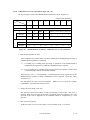
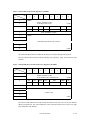
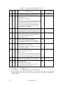
Table 1.1
Responses to Link Specification Commands
Flag
End Status
Status
Message
Link Function
0
Completed
Normally
INTERMEDIATE
LINKED TASK COMPLETE
Effective
1
Completed
Normally
INTERMEDIATE
LINKED TASK COMPLETE WITH
FLAG
Effective
u
Completed
Abnormally
CHECK CONDITION
TASK COMPLETE
Not Effective
0
Conditions Met
INTERMEDIATE
CONDITION MET
LINKED TASK COMPLETE
Effective
1
Conditions Met
INTERMEDIATE
CONDITION MET
LINKED TASK COMPLETE WITH
FLAG
Effective
u
Unable to Start
Receive
BUSY
TASK COMPLETE
Not Effective
u
Reserved State
RESERVATION
CONFLICT
TASK COMPLETE
Not Effective
u
Forced
Termination
COMMAND
TERMINATED
TASK COMPLETE
Not Effective
u
Queue Full State
QUEUE FULL
TASK COMPLETE
Not Effective
Only a single logical unit can operate a series of linked commands. When the IDD receives the
first command, the logical unit specified by the IDENTIFY message or the LUN field of the CDB
becomes the object of operation in a series of linked commands and the values specified in the
LUN field in the second and subsequent CDBs are disregarded.
Note:
An INIT which uses the command link function must make the ATN signal in the
SELECTION phase TRUE and notify the TARG that it is capable of receiving messages other
than the TASK COMPLETE message. If “1” has been specified in the Link bit of the CDB
without the ATN being made TRUE by the INIT in the SELECTION phase, the IDD
terminates that command abnormally by sending a CHECK CONDITION status (ILLEGAL
REQUEST [=5] / Invalid field in CDB [=24-00]).
1 - 12
C141-E124-01EN
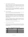
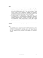
1.3.3
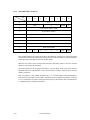
Disconnect/reconnect processing
When processing is performed by the TARG during the command execution process which does
not require operation on the SCSI bus, the TARG can return the SCSI bus to the BUS FREE phase
temporarily by disconnect processing and execute command internally. Through this function, the
INIT is enabled to process multiple commands on the SCSI bus.
(1)
Disconnect permission conditions and commands with executing disconnect process
If all of the conditions shown below for permitting a disconnect are satisfied, the IDD executes
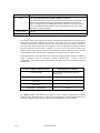
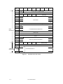
disconnect processing. However, As shown in Table 1.2, disconnect processing may be valid or
invalid, and the disconnect processing execution timing may differ, depending on the type of
command.
Conditions for Permitting a Disconnect
1) The SCSI ID of the INIT is notified in the SELECTION phase.
2) The INIT generates the ATTENTION condition in the SELECTION phase.
3) The INIT notifies the TARG that disconnect processing is permitted by an IDENTIFY
message.
C141-E124-01EN
1 - 13
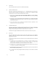
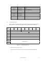
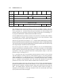
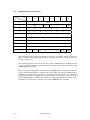
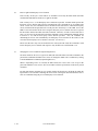
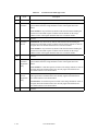
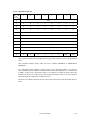
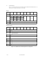
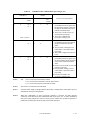
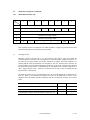
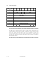
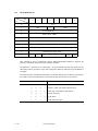
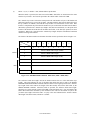
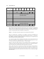
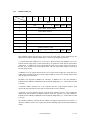
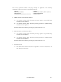
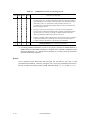
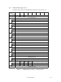
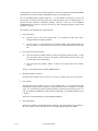
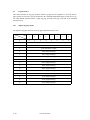
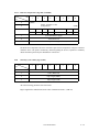
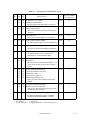
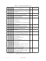
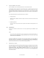
Table 1.2
Types of Command and Disconnect Processing
Commands with executing disconnect processing. (Note 2)
Commands without executing disconnect processing. (Note 1)
C
F
I
L
M
N
P
R
S
T
V
W
CHANGE DEFINITION
FORMAT UNIT
INQUIRY
LOG SELECT
LOG SENSE
MODE SELECT
MODE SELECT EXTENDED
MODE SENSE
MODE SENSE EXTENDED
(40)
(04)
(12)
(4C)
(4D)
(15)
(55)
(1A)
(5A)
PERSISTENT RESERVE IN
PERSISTENT RESERVE OUT
READ
READ BUFFER
READ CAPACITY
READ DEFECT DATA
READ EXTENDED
READ LONG
REASSIGN BLOCKS
RECEIVE DIAGNOSTIC RESULTS
RELEASE
REPORT DEVICE IDENTIFIER
REPORT LUN
REQUEST SENSE
RESERVE
REZERO UNIT
SEEK
SEEK EXTENDED
SEND DIAGNOSTIC
SET DEVICE IDENTIFIER
START/STOP UNIT
SYNCHRONIZE CACHE
TEST UNIT READY
VERIFY
WRITE
WRITE AND VERIFY
WRITE BUFFER
WRITE EXTENDED
WRITE LONG
WRITE SAME
(5E)
(5F)
(08)
(3C)
(25)
(37)
(28)
(3E)
(07)
(1C)
(17)
(A3)
(A0)
(03)
(16)
(01)
(0B)
(2B)
(1D)
(A4)
(1B)
(35)
(00)
(2F)
(0A)
(2E)
(3B)
(2A)
(3F)
(41)
O
O
O
O
O
O
O
O
O
O
O
O
O
O
O
O
O
O
O
O
O
O
O
O
O
O
O
O
O
O
O
O
O
O
O
O
O
O
(Note 1)
Commands without executing disconnect processing: In cases only where commands are
issued without a tag, queuing processing (see Section 1.4) and disconnect processing cannot be
performed in the execution sequence.
(Note 2)
Commands with executing disconnect processing: Regardless of command queuing, in a
command’s execution process (after the COMMAND phase is completed, or during or after the
completion of data transfer), disconnect processing is performed. However, in the case of commands
with a data state (in cases where it is hit in the cache, etc.), or with a number of processing modes,
1 - 14
C141-E124-01EN
other than cases where the command is in a queue, disconnect processing may not be executed
depending on the processing content specification of the command.
(2)
Basic disconnect processing procedure
Disconnect processing is executed basically by the following processing procedure.
1) If the IDD judges that it is possible for it to disconnect from the SCSI bus during execution of
a command, it sends a DISCONNECT message to the INIT and enters the BUS FREE phase.
At this time, if necessary, the IDD sends a message to activate a pointer in the INIT which
precedes sending of the DISCONNECT message. Furthermore, for details concerning
pointers, refer to the SCSI pointer description in “SCSI Physical Interface Specifications” and
“Chapter 2 SCSI Messages.”
2) After the IDD enters the BUS FREE phase, it is possible for the INIT to issue other commands.
Also, it is possible for an IDD which has performed disconnect processing to receive
input/output operation requests from each INIT (this is explained in the description of the
command queuing function in Section 1.4).
3) The IDD executes the command which performs disconnect processing internally.
4) After that, the IDD executes reconnection processing at the point, when it is necessary for
operation on the SCSI bus, to reconnect with the INIT (See item (6) concerning reconnection
processing).
(3)
Disconnect processing procedure after COMMAND phase execution
If commands are queued (see Section 1.4), disconnect processing is performed immediately after the
COMMAND phase execution is completed. In this case, the IDD switches from the COMMAND phase
to the MESSAGE IN phase and sends the DISCONNECT message to the INIT.
(4)
Disconnect processing procedure after data transfer execution
For commands which accompany a data transfer, disconnect processing may be performed during
DATA IN or DATA OUT phase execution or after transfer of the last data is completed. In this
case, caution is necessary when executing the following types of pointer controls.
a. If disconnecting during a data transfer
In cases where data transfer has begun (in DATA IN or DATA OUT phase) and it will take time
until transfer of subsequent data can be transferred (example: When the data buffer has been
emptied by a READ command, or the data buffer has ceased to be empty due to a WRITE
command), disconnect processing is performed during data transfer. In this case, the IDD sends
the SAVE DATA POINTER message before sending the DISCONNECT message. When the
INIT receives the SAVE DATA POINTER message, it must save the current value of the current
data pointer and make it possible to transfer data from the subsequent data at reconnection time.
C141-E124-01EN
1 - 15
b. If disconnecting after the final data transfer is completed
In the case of a disconnect after transfer of all the data necessary for execution of a command
has been completed normally, (example: a WRITE command), the IDD sends a
DISCONNECT message after sending the SAVE DATA POINTER message.
After that, the IDD executes reconnection processing and enters the STATUS phase
immediately and reports the status byte without requesting a data transfer.
Note:
In disconnect processing in this case, transfer of all the data accompanying execution of
the command is complete and there is actually no necessity for the SAVE DATA
POINTER message.
However, by issuing the SAVE DATA POINTER message, processing time increases due
to the message transfer, but as a result of the pointer restore operation that is executed
internally by the INIT during reconnection processing for the status report, the current
data pointer can reflect the final results of the data transfer.
(5)
Disconnect processing exceptions
When the previously mentioned disconnect processing is executed, if the ATTENTION condition is
generated for the DISCONNECT message sent by the IDD and the INIT returns the MESSAGE
REJECT message, the IDD executes the command with the connections to the SCSI bus remaining as is,
without executing disconnect processing. Cases of disconnect processing in which a pointer operation is
necessary and the SAVE DATA POINTER message is rejected are the same.
(6)
Reconnection processing procedure
The reconnection processing procedure is as shown below.
1) The IDD executes the ARBITRATION phase at the point when processing on the SCSI bus is
necessary and gets the SCSI bus control right, then reconnects with the INIT in the
RESELECTION phase.
2)
After that, the IDD sends the IDENTIFY message to the INIT and notifies it of the logical unit
number (LUN) necessary for reconnection processing. If a tagged queuing command is
executed, the IDD sends the SIMPLE message to inform the INIT of the tag ID. The INIT
reads the Saved pointer (command, data and status) corresponding to the LUN specified at this
time and restores it to the current pointer.
Note:
1)
1 - 16
If there is no response from the INIT within the specified time (default: 250 ms) in
the RESELECTION phase, the IDD performs timeout processing, then enters the
BUS FREE phase. In this case, after waiting 200 ms or longer, the IDD executes the
predetermined number of retries (re-executing the RESELECTION phase).
However, if it still cannot reconnect with the INIT after that, the IDD clears the
C141-E124-01EN
command necessary for reconnection processing and generates sense data indicating
ABORTED COMMAND[=B]/Select /Reselect failure[=45-00].
2)
If the INIT rejects the IDENTIFY message, or if it rejects the SIMPLE message
when executing a tagged queuing command, the IDD clears the command that was
being executed during reconnection processing and enters the BUS FREE phase. In
this case, the IDD generates sense data indicating ABORTED
COMMAND[=B]/Message error[=43-00].
3) After the INIT that accepts the IDENTIFY message normally completes the pointer restore
operation, it should make the ACK signal for the IDENTIFY message FALSE. If the
ATTENTION condition does not exist when the ACK signal becomes FALSE during sending
of the IDENTIFY message, the IDD regards the reconnection processing as having been
normally completed and begins subsequent processing.
For further details, refer to CHANGE DEFINITION parameter list (Reselection Retry,
Reselection Time-out Delay) in Section 3.1.4 and SCSI Bus (RESELECTION phase) in
Chapter 1 of “SCSI Physical Interface Specifications” and SCSI Bus Error Recovery
Processing in Chapter 3.
1.3.4
Synchronous mode data transfer/wide mode data transfer
The IDD equips a synchronous mode data transfer function and wide mode data transfer function
for processing high speed data transfers (DATA IN and DATA OUT phases) on the SCSI bus.
Data transfers on the SCSI bus can be executed in any desired combination of the asynchronous
mode or synchronous mode and in 8 bit widths or 16 bit widths (wide mode), but by using
synchronous mode data transfer or wide mode data transfer, command processing time is shortened
and throughput for input/output processing by multiple command processing using idle time on the
SCSI bus can be improved.
After IDD power on, after generating a RESET condition on the SCSI bus or after one of the INITs
issues a TARGET RESET message, the data transfer mode (default mode) of the IDD is the
asynchronous mode. To use wide mode data transfer, the INIT must exchange a WIDE DATA
TRANSFER REQUEST message or PARALLEL PROTOCOL REQUEST message with the IDD,
and determine the SCSI bus width. To use the synchronous mode data transfer, the INIT must
exchange the SYNCHRONOUS DATA TRANSFER REQUEST message or PARALLEL
PROTOCOL REQUEST message and determine parameters necessary for executing the
synchronous mode transfer. When exchange of the WIDE DATA TRANSFER REQUEST
message or PARALLEL PROTOCOL REQUEST message is completed, if the synchronous mode
has been established between the INIT and IDD previously, note that the asynchronous mode is
set.
The INIT which uses wide mode data transfer normally sends the WIDE DATA TRANSFER
REQUEST or PARALLEL PROTOCOL REQUEST message to the IDD following the IDENTIFY
message after the initial SELECTION phase, and requests the TARG (IDD) to set the SCSI bus
width in the wide mode. Also, if synchronous mode data transfer is used, after establishing the
SCSI bus width, the INIT exchanges the SYNCHRONOUS DATA TRANSFER REQUEST
message or PARALLEL PROTOCOL REQUEST message and requests the TARG (IDD) to set
the synchronous data transfer mode.
C141-E124-01EN
1 - 17
The data transfer mode set with the INIT once is effective until a RESET condition occurs or until
a TARGET RESET message is issued by any INITs. Therefore, in order for the INIT to avoid
overhead time for message exchange, the INIT should not send the WIDE DATA TRANSFER
REQUEST message and the SYNCHRONOUS DATA TRANSFER REQUEST message or
PARALLEL PROTOCOL REQUEST message to the TARG each time the SELECTION phase is
executed.
When the requesting synchronous mode transfer/wide mode data transfer by specifying of the
CHANGE DEFINITION command (synchronous mode transfer/wide mode data transfer request)
is permitted, and the IDD is maintaining the default transfer mode (asynchronous, 8-bit width), if a
WIDE DATA TRANSFER REQUEST message is not sent from the INIT, the IDD enters the
MESSAGE IN phase immediately after the COMMAND phase and sends the WIDE DATA
TRANSFER REQUEST message to the INIT for attempting to set the 16-bit width mode. After
establishing the bus width, the IDD sends the SYNCHRONOUS DATA TRANSFER REQUEST
message to the INIT and attempts the synchronous mode transfer parameters (REQ/ACK offset =
127, Transfer period = 25 ns).
The IDD maintains data transfer mode settings between itself and each INIT individually.
Therefore, an INIT which uses asynchronous mode transfer and an INIT which uses synchronous
mode transfer can both coexist on the same SCSI bus. Also, the parameters for synchronous mode
transfers decided by the SYNCHRONOUS DATA TRANSFER REQUEST message can differ for
each INIT and an INIT which uses the 8-bit width transfer mode can coexist with an INIT which
uses the 16-bit width transfer mode.
Note:
When the INIT issues the first command after the TARG’s power is switched on, or after a
RESET condition occurs, it can send the WIDE DATA TRANSFER REQUEST message and
the SYNCHRONOUS DATA TRANSFER REQUEST message. However, when the TARG is
set internally on a data transfer mode established previously by a TARGET RESET message
issued by another INIT, generally, the INIT is not aware of it. In such case, when requesting
synchronous mode/wide mode transfer is permitted by the specification of the CHANGE
DEFINITION command (synchronous mode/wide mode transfer request), the TARG (IDD)
sends the WIDE DATA TRANSFER REQUEST and SYNCHRONOUS DATA TRANSFER
messages to establish the synchronous mode/wide mode transfer again. Thus, the INIT shall
respond to these messages for setting necessary parameters again.
See “CHANGE DEFINITION” in Section 3.1.4, SCSI Bus (INFORMATION TRANSFER Phase)
in Chapter 1 and SCSI Messages (SYNCHRONOUS DATA TRANSFER REQUEST, WIDE
DATA TRANSFER REQUEST, PARALLEL PROTOCOL REQUEST) in Chapter 2 of “SCSI
Physical Interface Specifications” for further details.
1 - 18
C141-E124-01EN
1.4
Command Queuing Function
The IDD equips a command queuing function. Through queuing of commands, the IDD can
receive multiple commands in advance and execute them.
There are two methods used in the queuing function, tagged and untagged. In tagged queuing, the
IDD can receive multiple commands from each INIT. In untagged queuing, the IDD can receive a
single command from each INIT.
Both queuing methods are possible for the IDD, but an INIT can use only one queuing method at a
time. However, if another INIT selects a different method, the IDD controls both methods of
command queuing.
1.4.1
Untagged queuing
Using untagged queuing, the IDD can receive a command from an INIT while it is executing
processing of a command from another INIT. The IDD can receive one command at a time from
each INIT. It is the role of the INIT to confirm that only one command is issued every time.
When the IDD receives a new command from an INIT, if it is processing another command from a
different INIT, or if it is currently executing its initial self-diagnosis, that command is queued in
the command queue. In this case, the IDD executes disconnect processing after command queuing
processing is completed.
After the IDD finishes executing the current processing command, if there is a command in the
queue, it fetches that command and executes it. If there are multiple commands in the queue, they
are fetched and executed in the order in which they were received.
When a command is in the queued state, if a RESET condition occurs, or if the IDD receives a
TARGET RESET message from any INIT, it clears all the commands in the queue. At this time,
the IDD generates on UNIT ATTENTION condition for all the INITs.
When an ABORT message is sent from an INIT that has issued a command which is in the queue,
if the correct LUN (0) is specified, only the command issued by that INIT is cleared and the other
commands in the queue are not effected. If the LUN is not identified, an ABORT message which
specifies an illegal LUN (1 to 7) does not effect the commands in the queue.
Untagged queuing exception processing (events and operations executed by the IDD) is shown
below.
• If the TEST UNIT READY, REQUEST SENSE or INQUIRY command is received.
When one of these commands is received, if there is no link instruction in that command, the IDD
executes that command immediately without queuing the command or executing disconnect
processing. At this time, there is no effect on the commands from other INITs which are currently
being executed, or on the commands in the queue.
If these commands contain link instructions, they are queued.
C141-E124-01EN
1 - 19
• If disconnect processing is impossible.
If disconnect processing is impossible because the INIT which issued the command does not meet
the conditions for permitting a disconnect (see Section 1.3.3), or if the DISCONNECT message is
rejected by the INIT even though it meets the conditions for permitting a disconnect, the IDD
responds with a BUSY status without queuing the received command except the case described in
item 1) in following Note during executing or queuing command already. If this is not the case,
the received command is executed immediately.
• If the IDD is reserved
If the IDD has been reserved by an INIT using the RESERVE command and receives a TEST
UNIT READY command after that, when that command conflicts with the reserved state, it
responds with a RESERVATION CONFLICT status. Commands after that are queued, and the
reserved state is checked when a command is fetched from the queue. Conflicts with the reserved
state are explained in the description of the RESERVE command (Section 3.1.11).
Note:
Through the operation of the command queuing function, except for exceptions described on
this page, the IDD does not respond to commands issued by the INIT with a BUSY status.
This function is applied under the multi-initiator environment, and overhead for re-issuing
commands caused by the BUSY status is unnecessary. Normally, the INIT does not have to be
aware of the existence of a queuing function, but it is necessary to exercise caution in the
following items when controlling input/output processing.
1 - 20
1)
When a command is queued, the time from the queuing of the command to its actual
execution will vary depending on the commands already in the queue, or on the content of
the processing currently being executed. Particularly in cases where the FORMAT UNIT
command and START/STOP UNIT command (Immed = 0), and data access commands
which specify large processing block counts, are already queued or being executed, the
newly queued command will be forced to wait a long time until it is executed.
2)
In the following cases, a command may not be executed even after it has been queued.
a)
When there is an error in the CDB, the IDD responds with a CHECK CONDITION
status at the point when that command is fetched from the queue.
b)
If the IDD is in the not ready state at the point when the queued command is fetched,
it responds with a CHECK CONDITION status.
c)
If a UNIT ATTENTION condition is generated before the queued command is
fetched, a CHECK CONDITION status may be replied.
C141-E124-01EN
1.4.2
Tagged queuing
Through the tagged queuing function, the IDD can receive multiple commands from the same INIT
or from different INITs until the command queue is full. The number of commands that it is
possible to receive by the IDD is 128 maximum, without relation to the INIT. When the IDD
receives a new command, if the command queue is full, it responds to the new command with the
QUEUE FULL status.
The IDD manages the command queue, but it is possible for the INIT to add or clear commands
from the queue. When adding a command to the queue, it is possible for the INIT to specify the
order in which commands should be executed or the command that should be executed next to the
IDD.
If the disconnect right is not recognized in the IDENTIFY message of a tagged command, the IDD
responds with a BUSY status.
Through the QUEUE TAG message, the INIT can attach a unique tag (ID) to each command. The
INIT can set that command’s pointer correctly by the tag sent when the IDD reconnects. One INIT
can issue multiple commands to the IDD only when the respective commands have unique tags.
If an ORDERED message is used, the IDD executes the other commands not included in the
ORDERED message in the order in which they are received. All commands received with a
SIMPLE message before commands are received with an ORDERED message are executed before
those commands received with the ORDERED message. All commands with SIMPLE messages
received after commands received with the ORDERED message are executed after the commands
received with the ORDERED message.
Commands received with a HEAD OF QUEUE message are registered at the top of the queue for
waiting execution. The IDD does not interrupt the current command execution and executes them
after completion of current command execution. When commands with the HEAD OF QUEUE
message are received continuously, the IDD first executes the command which was received last.
During the IDD executes or queues a tagged command, the same INIT must issue untagged
commands except when the IDD is in the sense hold state.
The IDD handles a series of linked commands as if it were processing a single command and
processes the series of commands by the tag received with the first command. A command with a
HEAD OF QUEUE received before processing of a series of linked commands is completed is
executed by the IDD after all the linked commands in the series have been executed.
The RESERVE, RELEASE and RESERVE EXTENDED commands should be issued together
with an ORDERED message. If the HEAD OF QUEUE message is used with these commands,
previously issued commands and reserved states may become redundant.
The TEST UNIT READY and INQUIRY commands do not influence the state of the IDD, so they
can be issued together with a HEAD OF QUEUE message.
The INIT can specify 2 error recovery options by the QErr bit of the control mode parameter (Page
A) of the mode select parameters.
C141-E124-01EN
1 - 21
When “0” is specified in the QErr bit, the IDD enters any one of a number of sense hold states, and
when this state is released, it continues to execute the commands in the queue. The IDD queues
any commands received from other INITs while it is in the sense hold state, but during this period,
execution of all the commands in the queue is interrupted.
If “1” is specified in the QErr bit, if the IDD enters any one of a number of sense hold states, the
queue is cleared after the sense hold state is released. When the queue is cleared through this
recovery option, the UNIT ATTENTION condition is generated for all the INITs which had their
commands cleared (excluding the INIT that set the sense hold state). The sense code Commands
cleared by another INIT [=2F-00] is set.
Deferred errors are reported for all commands that have already been completed. Therefore, the
queue tag values attached to those commands are not reported.
If a QUEUE TAG message is received by the IDD when tagged commands are prohibited by the
DQue bit of the control mode page, the IDD rejects the message with the MESSAGE REJECT
message processes the accompanying command as an untagged command.
The ABORT TASK SET, ABORT TASK, TARGET RESET or CLEAR TASK SET message is
used to clear some or all of the commands in the queue. See “SCSI Physical Interface
Specifications” for details.
If ‘0001’ is specified in the Queue algorithm modifier of the control mode page, the IDD performs
command reordering processing of commands issued with a SIMPLE message. Reordering
processing is performed with the objective of reducing total processing time for command
processing.
• Conditions for Reordering:
If a command which is the object of reordering is issued by an INIT that permits reordering
with an accompanying SIMPLE message.
• Commands which are Objects of Reordering:
READ, READ EXTENDED, WRITE, WRITE EXTENDED
If an INIT permits command reordering processing, the IDD changes the processing order of the
commands. It is necessary for the INIT to manage concerning the legality of the data, etc.
Section 4.1.7, “Control mode parameters (page code = 0A)” for details of the control mode page.
1 - 22
C141-E124-01EN
1.5
UNIT ATTENTION Condition
The UNIT ATTENTION condition is a function used to notify the INIT asynchronously of an
event (status change) that has occurred in the TARG or logical unit.
1.5.1
Generation of the UNIT ATTENTION condition
Events which cause a UNIT ATTENTION condition to be generated are one of the following.
(1)
When power on, RESET or TARGET RESET occurs
If the IDD’s power is switched on, the IDD enters the RESET condition or is reset by a TARGET
RESET message, this UNIT ATTENTION condition is generated for all the INITs, regardless of
whether the disk drive is in the ready state or not.
(2)
Mode parameters changed (changed by another INIT)
If the parameters specified in the MODE SELECT or MODE SELECT EXTENDED command are
changed by any INIT, a UNIT ATTENTION condition is generated for all the INITs other than the
INIT which changed the parameters.
(3)
Commands cleared by another INIT
Commands which are being executed or which are queued are cleared if one of the following
events occurs, and this UNIT ATTENTION condition is generated.
•
The CLEAR TASK SET message is issued by any INIT.
•
Tagged queuing is prohibited by a MODE SELECT or MODE SELECT EXTENDED
command (Page A send) from any INIT. (DQue = “1”)
•
The sense hold state of an INIT is released when “1” is specified in the QErr bit of MODE
SELECT parameter page A.
However, the IDD does not enter the UNIT ATTENTION condition hold state for an INIT that
issues a CLEAR TASK SET message, an INIT that issues a MODE SELECT or MODE SELECT
EXTENDED command, or an INIT that releases the sense hold state.
(4)
Changed operating definition
When the operation mode is changed by the CHANGE DEFINITION command, the UNIT
ATTENTION condition is generated for all INITs.
C141-E124-01EN
1 - 23
1.5.2
Response and Release Condition at UNIT ATTENTION Condition Hold State
A UNIT ATTENTION condition generated by the IDD by the occurrence of the previously
mentioned events is held individually for each INIT and it is held until it is released by the INIT it
is held for issuing the commands specified below.
When the IDD is holding a UNIT ATTENTION condition, if the IDD receives a command from
the INIT that the UNIT ATTENTION condition is held for, it performs one of the following
operations depending on the type of command issued.
(1)
Commands other than the INQUIRY and REQUEST SENSE commands
The IDD reports a CHECK CONDITION status to the issue command. The UNIT ATTENTION
condition for that INIT is then cleared by the CHECK CONDITION status report. The sense key of the
sense data generated at this time is UNIT ATTENTION [=6] and the sense codes shown below indicate
the event that generated the UNIT ATTENTION condition.
x
Power on
[=29-01]
x
Reset
[=29-02]
x
TARGET RESET
[=29-03]
x
Transciever Mode Changed to SINGLE-ENDED
[=29-05]
x
Transciever Mode Changed to LVD
[=29-06]
x
Mode parameters changed
[=2A-01]
x
Reservations Preempted
[=2A-03]
x
Reservations Released
[=2A-04]
x
Registrations Preempted
[=2A-05]
x
Commands cleared by another INIT
[=2F-00]
x
Spindle synchronized
[=5C-01]
x
Spindle not synchronized
[=5C-02]
x
Microcode has been changed
[=3F-01]
x
Changed Operating Definition
[=3F-02]
x
Device Identifier Changed
[=3F-05]
However, if the IDD responds with a BUSY status or QUEUE FULL status due to its not being able to
receive the command that was issued, the UNIT ATTENTION condition is not cleared.
The above CHECK CONDITION status response that is the cause of the UNIT ATTENTION
condition hold can be prohibited by the specification of the CHANGE DEFINITION command.
When the CHECK CONDITION status response is prohibited, the IDD executes the commands it
receives normally, except in the case of a RESERVATION CONFLICT status, BUSY status or
QUEUE FULL status. In this case, the UNIT ATTENTION condition for the INIT that issued that
command is cleared.
See Section 3.1.4 “CHANGE DEFINITION” concerning setting details.
1 - 24
C141-E124-01EN
(2)
INQUIRY command
The INQUIRY command is executed normally, but the UNIT ATTENTION condition is not cleared.
(3)
REQUEST SENSE command
One of the following operations is performed depending on whether or not the IDD is in the sense
data hold state (shown in Section 1.6).
a. In the case of a Sense Data Hold state
The IDD executes the REQUEST SENSE command normally and sends the sense data which
are being held to the INIT. In this case, the UNIT ATTENTION condition is not cleared.
b. In the case of a State other than a Sense Data Hold state
The IDD executes the REQUEST SENSE command normally and sends the sense data which
indicate the UNIT ATTENTION condition and are being held to the INIT. At this time, the
UNIT ATTENTION condition for that INIT is cleared.
1.5.3
UNIT ATTENTION condition multiple hold
If any UNIT ATTENTION condition is generated and a new UNIT ATTENTION condition is
generated for a different reason before the INIT for which the first UNIT ATTENTION condition
was held clears it, those UNIT ATTENTION conditions are held together, and the IDD reports
these multiple UNIT ATTENTION conditions in sequence. For example, a “Mode parameters
changed,” “Spindle Synchronized” or “Spindle not Synchronized” or other UNIT ATTENTION
condition may be reported after the “Power on, RESET or TARGET RESET occurred” UNIT
ATTENTION condition is reported.
C141-E124-01EN
1 - 25
1.6
Sense Data Hold State
1.6.1
Sense data hold condition
The IDD generates sense data if any of the following conditions occurs and enters the sense data
hold state until the conditions for cancellation, described in Section 1.6.2, are established. The
sense data which are generated, are held for each individual INIT that issued the applicable
command. The sense data hold state is also maintained individually for each INIT which is their
object.
1) If the IDD reports a CHECK CONDITION status, sense data is generated for the command
that was terminated by the CHECK CONDITION status.
2) If a fatal error occurs on the SCSI bus and the IDD forcibly enters the BUS FREE phase, sense
data is generated for the command that was being executed on the SCSI bus. However, if the
LUN cannot be identified by the point when the error occurs, the IDD does not generate sense
data.
3) Since it is impossible for reconnection processing to be executed without a response from the
INIT in the RESELECTION phase, if the IDD clears the command that is necessary for
reconnection processing, sense data is generated for that command.
Notes:
1 - 26
1.
In the case of 3) above, the IDD does not clearly inform the INIT of the occurrence of an
error, but terminates the command abnormally and enters the sense data hold state. If a
long period of time passes with no response from the IDD, the INIT that issued the
command should issue a REQUEST SENSE command and confirm the content of the
error.
2.
If the INIT which is the object of holding of sense data cannot be identified because the
INIT’s SCSI ID was not notified in the SELECTION phase, the INIT enters an
unspecified special sense data hold state. In this case, the IDD regards this as the INIT
that is the object of holding of the sense data starting a new SELECTION phase in which
the INIT’s SCSI ID is not notified.
C141-E124-01EN
1.6.2
Response and release conditions at sense data hold state
The response of the IDD when it receives a new command while it is in the sense data hold state,
and conditions for releasing the sense data hold state are shown below.
1) If a command is issued to the logical unit in the sense data hold state by the INIT which is the
object of sense data holding.
–
–
In the case of an untagged command
REQUEST SENSE command:
The sense data held by the IDD are transferred to the INIT
and the sense hold state is released.
Other commands:
The sense data hold state is released and the command is
executed normally if commands issued from the INIT are
not queued. If commands issued from the INIT are queued,
the commands are treated as overlapping commands.
In the case of a tagged command
The BUSY status is reported and the sense data hold state is released.
2) If a command is issued to the logical unit in the sense data hold state from an INIT which is not
the object of sense data holding, the sense data hold state is not released and the command is
queued.
3) In the following cases, the sense data hold state is released and the sense data being held are
lost.
–
The RESET condition occurs on the SCSI bus.
–
A TARGET RESET message is issued by any INIT.
–
An ABORT TASK SET message is issued by an INIT for which sense data held for the logical
unit in the sense data hold state.
C141-E124-01EN
1 - 27
1.7
Command Processing Exceptions
1.7.1
Overlapping commands
If the following state occurs, the IDD recognizes that overlapping commands have been generated
and the command is terminated abnormally.
1) During the IDD is executing or queuing an untagged command, the INIT that issued that
command before the completion of the command execution issues either an untagged
command or a tagged command.
2) If the IDD is executing or queuing a tagged command, the INIT that issued that command
before the completion of the command execution issues another tagged command with the
same tag specified as the previous command or an untagged command.
Normally, completion of a command execution is at the point when the TARG notifies the INIT of
the TASK COMPLETE message. Execution of a command can also be terminated by the RESET
condition, a TARGET RESET message, CLEAR TASK SET message, ABORT TASK SET
message or ABORT TASK message.
The IDD abnormally terminates all the commands (commands being executed or queued) received
from an INIT which is overlapping commands and the command that generated the overlap
condition by the procedure described below.
1) If the command received form the INIT is being executed, the IDD stops execution of the
command. If the command is still in the queue and execution has not been started, the IDD
clears that command.
2) The IDD reports a CHECK CONDITION status for a command that generates an overlap. At
this time, the sense data generated by the IDD indicates ABORTED COMMAND
[=B]/Overlapped commands attempted [=4E-00], or Tagged Overlapped [=4D-nn] (nn: tag
No.).
Notes:
1 - 28
1)
In order for the INIT to stop processing of a command during a disconnect, it is
permitted to send an ABORT TASK message, ABORT TASK SET message,
CLEAR TASK SET message or TARGET RESET message with specifying the
logical unit (see Section 1.7.6).
2)
Specification of overlapping commands applies without dependence upon the type of
command that is issued second. For example, even if the command issued second is
the INQUIRY or REQUEST SENSE command, the IDD reports the CHECK
CONDITION status and terminates both the first command and the second command
abnormally.
C141-E124-01EN
1.7.2
Illegal LUN specification
The logical unit number (LUN) supported by the IDD is LUN = 0 only. If a LUN other than this
(1 to 7) is specified, the IDD performs one of the following operations, depending on the type of
command issued at that time.
1) The INQUIRY command is executed normally even if the LUN specification is illegal.
However, byte 0 of the “Standard INQUIRY Data” (“Qualifier” field and “Device Type Code”
field) transferred to the INIT for that command indicates X ‘7F.’
2) The REQUEST SENSE command is executed normally even if the LUN specification is
illegal. However, the sense data transferred to the INIT for that command indicates that the
LUN specification is illegal (ILLEGAL REQUEST [=5]/Logical unit not supported [=25-00]).
3) If an illegal LUN is specified for a command other than the INQUIRY command or REQUEST
SENSE command, that command is terminated abnormally with a CHECK CONDITION
status. The sense data generated at this time indicate that the LUN specification is illegal
(ILLEGAL REQUEST [=5] /Logical unit not supported [=25-00]).
1.7.3
Reserved operation code
Group 7 command operation codes (X ‘E0’ to X ‘FF’) are reserved by Fujitsu. When any
command is issued which includes these operation codes, the IDD does not always respond with a
CHECK CONDITION status (ILLEGAL REQUEST [=5] / Invalid command operation code [=2000]. The INIT should not issue commands which contain these operation codes.
1.7.4
Command processing in the not ready state
After the IDD’s power is switched on, the initial self-diagnosis is completed normally and the
spindle motor reaches the normal rotational speed, “system information,” which includes such
information as MODE SELECT parameters and disk media defect information is read from the
system space on the disk drive and each type of control information is initialized. When this
operation is completed, the IDD is in a state where it can be used (ready state). Furthermore, the
not ready state is defined as the IDD being in either of the following states.
• When the spindle motor has not reached the normal rotational speed.
• When reading of system information is not completed, or reading failed.
Also, if initialization of the disk media (formatting) has not been completed normally, it will be
impossible to access data on the disk media.
Processing of and response to commands received by the IDD when it is in the not ready state or in
the initialization incomplete state are described below. Furthermore, starting control of the spindle
motor when the power is switched on can be selected from either or two methods, through the
setting terminal (motor start mode) on the IDD, with rotation started at the same time as when the
power is switched on or through the START/STOP UNIT command.
C141-E124-01EN
1 - 29
(1)
General response in not ready state
The IDD reports a CHECK CONDITION status for a command, except in cases where the
command is one of the commands in item (2). The sense data generated at this time depends on
the state of the IDD, as shown in Table 1.3.
Table 1.3
IDD State
(2)
Sense data in not ready state
Sense Key
Spindle motor not
rotating at normal speed.
NOT READY
Reading system
information have not
completed.
Reading system
information failed.
NOT READY
Sense Code
Logical unit not ready
[=2]
[=04-01]
Logical unit not ready
[=2]
[=04-01]
HARDWARE ERROR
[=4]
Logical unit failed self-configuration
[=4C-nn]
Commands that can be executed even in the not ready state
If the IDD receives any of the following commands, it executes those commands even if it is in the
Not Ready state.
• START/STOP UNIT command
• RESERVE command
• RELEASE command
• WRITE BUFFER command
• READ BUFFER command
• INQUIRY command
• REQUEST SENSE command: The REQUEST SENSE command is executed normally. If the
IDD is in the sense data hold state, the sense data being held at that time are transferred to the
INIT. If not, sense data appropriate to the IDD’s state at that time are transferred to the INIT (See
Table 1.3).
• REZERO UNIT command: If the spindle motor has reached the normal rotational speed, this
command is executed even if reading of system information failed. If the spindle motor has not
reached the normal rotating speed, or if reading of system information is still in progress, a
CHECK CONDITION status is reported as in item (1).
1 - 30
C141-E124-01EN
(3)
Operation if formatting is not completed normally
While the FORMAT UNIT command is not being executed after a change in data format related
parameters by the MODE SELECT command, if the FORMAT UNIT command is terminated
abnormally for any reason (example: power cut off or RESET condition), the data on the disk
media cannot be accessed normally. In this case, the IDD reports a CHECK CONDITION status
for the command accessing the disk media.
The sense data generated at this time indicate a MEDIUM ERROR [=3] / Medium format
corrupted [=31-00] in the case of the former and MEDIUM ERROR [=3] / FORMAT command
failed [=31-01]. In either case, the IDD is restored to the ready state by reinitializing the disk
media using the FORMAT UNIT command.
1.7.5
Error recovery processing
If an error is detected an recoverable error on the SCSI bus or internally in the IDD, the IDD
attempts recovery processing of the detected error during command execution.
The INIT can specify detailed parameters related to error recovery processing and whether or not
there is a report for errors which were successfully recovered by using the MODE SELECT or
MODE SELECT EXTENDED command. It can also save those parameters in accordance with
INIT specifications in the system space on the disk media, and can change them temporarily
without saving them. After the power is switched on, or after a reset (RESET condition or
TARGET RESET message), the saved parameters are read and the error recovery processing
procedures is initialized.
See Section 3.1.5 “MODE SELECT” and Section 3.1.6 “MODE SELECT EXTENDED” for details of
the MODE SELECT or MODE SELECT EXTENDED command. See Section 5.3 “Disk Drive Error
Recovery Processing” and Chapter 3, “SCSI Bus Error Recovery Processing” of “SCSI Physical
Interface Specifications” for details of error recovery processing.
An outline of error recovery processing executed by the IDD is shown below.
(1)
Recovery processing for errors on SCSI bus
The IDD does not perform recovery processing for error detected on the SCSI bus. When error
recovery is impossible, or when a critical error related to SCSI bus protocols is detected, the IDD
may transfer the SCSI bus forcibly to the BUS FREE phase and clear the command that is
currently being executed.
Table 1.4
Item
1
2
3
4
5
6
Outline of SCSI Bus Error Recovery Processing
Type of Error
MESSAGE OUT phase parity error
COMMAND phase parity error
DATA OUT phase parity error
Received INITIATOR DETECTED ERROR message.
Received MESSAGE PARITY ERROR message.
RESELECTION phase time-out
C141-E124-01EN
Error Recovery Processing
“CHECK CONDITION” Status
“CHECK CONDITION” Status
“CHECK CONDITION” Status
“CHECK CONDITION” Status
“CHECK CONDITION” Status
Re-execute RESELECTION phase.
1 - 31
(2)
Recovery procedures for disk drive errors
The IDD executes error recovery listed in Table 1.5 for an error detected during access to data on
the disk. Note that the recovery increases command processing time because of rotation delay for
repositioning to the data block on the disk or initialization of the positioning control system.
The INIT can use the MODE SELECT parameter Page 1 (read/write error recovery parameter),
Page 7 (verify error recovery parameter), and Page 21 (additional error recovery parameter) to
control the retry count. However, use the default value specified by the IDD in general operation.
Table 1.5
Item
Outline of disk drive error recovery processing
Type of Error
Error Recovery Processing
1
Seek Error
Rezero (Return to Zero Cylinder), readjustment of positioning
control system, and repositioning to the data block.
2
Uncorrectable Data Error
Reread
3
Correctable Data Error
Correct by ECC.
Note:
The execution start timing of this automatic readjustment operation generally cannot be
predicted by the INIT. The automatic readjustment operation is performed when there are no
commands being executed or in the queue, but execution of commands issued immediately
after the IDD starts the readjustment operation, are forced to wait until the readjustment
operation is completed.
1 - 32
C141-E124-01EN
1.7.6
Reset processing
The INIT can reset the SCSI bus with following.
x
x
x
x
x
RESET condition
TARGET RESET message
CLEAR TASK SET message
ABORT TASK SET message
ABORT TASK message
The RESET condition resets all the SCSI devices connected on the same SCSI bus. The IDD is
initialized to the same state as when its power is switched on by the RESET condition, with the
currently executed command as well as all the commands in the queue cleared.
The TARGET RESET message resets only specific SCSI device (TARG) selected by the INIT,
and can initialize that TARG to the same state as when its power is switched on. However in a
multi-initiator environment, caution concerning clearing of commands issued by other INITs is
necessary.
The CLEAR TASK SET message clears all commands that the IDD is executing or queuing. The
previously set environment and conditions, such as MODE SELECT parameters, are not changed.
An INIT which wants to clear only specific commands it has issued itself must use an ABORT
TASK SET message or an ABORT TASK message. In this case, the INIT generates an
ATTENTION condition at the desired point in time if that command is currently being executed on
the SCSI bus, then sends the ABORT TASK SET message to the TARG. Also, if there is a
disconnect in effect, after the INIT selects the TARG, an ABORT message, in the case of an
untagged command, or an ABORT TASK message, in the case of a tagged command, is sent
following an IDENTIFY message which specifies the object logical unit, or the INIT waits until a
reconnection request occurs, then sends an ABORT TASK SET message or ABORT TASK
message. In the case of an ABORT TASK SET message, only the commands issued previously in
the logical unit specified at that time by the INIT that issues the ABORT TASK SET message
(currently being executed or queuing) are cleared and there is no influence on the other commands.
When an ABORT TASK message is received, only the command issued to the logical unit
specified at that time by the INIT which issued the ABORT TASK message is cleared, and there is
no influence on the other commands. No status byte or TASK COMPLETE message concerning
commands cleared in this processing is reported.
In particular, in the case of clearing of a write operation command for writing to the disk media
which is currently being executed, the IDD stops processing of that command as shown in Table
1.6. The case of halting an overlapping command that is currently being executed (see Section
1.7.1) is the same. The INIT must determine the complete completion state and if necessary, must
execute data recovery processing.
C141-E124-01EN
1 - 33
Table 1.6
Type of command
Reset processing during write
Halting process of command execution
WRITE
WRITE EXTENDED
WRITE AND VERIFY
SEND DIAGNOSTIC (Write/Read Test)
WRITE LONG
WRITE SAME
Data blocks which are currently being written are
processed normally, including the ECC portion, and
execution of the command is terminated at the point when
that processing is completed. Not all the data transferred
from the INIT to the IDD will necessarily be written to the
disk media. If the ATN signal is asserted immediately
after data transfer in the DATA OUT phase (to the first
ACK signal) and the ABORT TASK SET message is sent,
the data are not written to the disk media.
FORMAT UNIT
At the point when processing of the data block that is
currently being written (initialized) is completed,
execution of the command is halted. Since the formatting
results cannot be guaranteed for the entire disk surface, it
is necessary for the INIT to reissue the command.
REASSIGN BLOCKS
At the point when processing of alternate blocks which are
currently being assigned is completed, execution of the
command is halted. Not all the alternate blocks specified
for reassignment processing by the INIT will necessarily
have been processed.
MODE SELECT
MODE SELECT EXTENDED
LOG SENSE (Specifying parameter save)
If a parameter save operation has already started, that
command is executed until it is completed. However,
since the INIT cannot judge whether the parameters have
been saved or not, it is necessary for the INIT to confirm
the status by the MODE SENSE command or the LOG
SENSE command, or reissue the command.
SYNCHRONIZE CACHE
Data blocks which are currently being written are
processed normally, including the ECC portion and the
command is halted at the point when that processing is
completed. Not all the data which is the write object will
necessarily be written to the disk media.
1 - 34
C141-E124-01EN
1.7.7
Fatal hardware errors
(1)
Self-diagnostic errors
If a hardware fatal error is detected during the initial self-diagnosis, in off-line self diagnosis or in
on-line self-diagnosis (SEND DIAGNOSTIC command), rotation of the spindle motor will be
halted.
When in this state, the IDD reports the CHECK CONDITION status for all input/output operation
requests except the REQUEST SENSE command. The sense data reported at this time indicate
HARDWARE ERROR [=4] / Diagnostic failure on component “nn” [=40-nn]. It is necessary for
the INIT either to generate a RESET condition or send a TARGET RESET message and attempt to
recover from the error state. For recommended procedures for error recovery methods, see the
explanation in Section 5.2 “INIT’s Error Recovery Methods (Recommended).” Furthermore, see
Section 6.1.1 “Self-diagnostic Function” in “Product Manual.”
(2)
Unrecoverable hardware errors
Limited to cases in which a fatal hardware error occurs during execution of a command, and
termination processing such as a CHECK CONDITION status report cannot be executed, the IDD
may halt rotation of the spindle motor.
After this state occurs, the IDD reports the CHECK CONDITION status for all input/output
operation requests except the REQUEST SENSE command. The sense data reported at this time
indicate HARDWARE ERROR [=4] / Internal target failure [=44-nn]. If this state is reported
continuously for input/output operation requests, it is necessary for the INIT to generate a RESET
condition or send a TARGET RESET message and attempt to recover from the error state. For
recommended procedures for error recovery methods by the INIT, see the explanation in Section
5.2 “INIT’s Error Recovery Methods (Recommended).”
C141-E124-01EN
1 - 35
1.8
Data Block Addressing
1.8.1
Definition of data space
The IDD manages the data storage area on the disk drive in the following 2 types of data space.
x
x
User space: user data storage area
System space: IDD exclusive area
Within these 2 areas, the user can clearly access the user space. The data format and defect
management methods in this space are the same and it is possible to access this space by logical
data block addressing described in Section 1.8.2. System space is accessed by the IDD internally
when the power is switched on or during processing of specific commands, but it cannot be
accessed directly by the user.
Figure 1.5 shows the data space configuration on the disk drive. The number of cylinders allocated
to user space can be specified by the user (MODE SELECT or MODE SELECT EXTENDED
command).
A spare sector area (alternate area) for use as alternate sectors for defective sectors is allocated in
the user space. The IDD manages defects for each cell, which consists of several cylinders (see
Figure 1.5). The user can allocate the number of sectors in the last track of each cell and the
number of cylinders in the user space (alternate use cylinders) as the alternate area (by the MODE
SELECT or MODE SELECT EXTENDED command). Only one cylinder can be specified as an
alternate cylinder for the IDD.
Alternate data blocks are allocated in defect sector units for defective sectors on the disk media
through internal IDD defect management. Through this defect management, the INIT can access
all the logical data blocks in the user space as if they were error free.
For details concerning the data format on the disk media (cylinder configuration, track format and
sector format) and details concerning defect management techniques and alternate block allocation
techniques, Chapter 3 “Data Format” in the “Product Manual.” For an outline of defect
management techniques, see “Disk Media Management” in Chapter 6 of this manual.
1 - 36
C141-E124-01EN
Physical cylinder
[System space]
Track 0
Cylinder 0
Track 0
Cylinder 1
Cell 0
Track 0
Zone 0
Cylinder (a-1)
Cell 1
[User space]
Track 0
Alternate cylinder (b-1)
(b cylinders)
Zone 1
Cylinder (a-1)
Zone (x-1)
Alternate
cylinder
(c cylinders)
Last cylinder (d-1)
(Last cylinder)
Figure 1.5
Data space configuration
C141-E124-01EN
1 - 37
1.8.2
Logical block addressing
The IDD uses logical data block addressing which is not dependent on the disk drive’s physical
structure as the method of data access on the disk medium. The IDD makes correspondence
between each physical sector and each logical data clock address during formatting. Access to the
data on the disk medium is performed in logical data block units and the INIT specifies the logical
data block address that is its object during access.
In logical data block addressing, specifying of a data block address is a function which specifies 2
continuous binary numbers for each drive. Furthermore, the INIT can know the logical data block
address range in the user space where specification is possible using the READ CAPACITY
command.
(1)
User space logical block addresses
The top data block in the user space is made logical data block address “0,” then continuous
logical data block addresses are allocated to each data block until the last data block in the user
space.
The IDD makes cylinder 0, track 0 sector 0 the top logical data block, and allocates subsequent
logical data blocks in the order described below to addresses in ascending order.
1) Within the same track, logical data blocks are allocated to sector numbers in ascending order.
2) Within the same cylinder, excluding the final track, succeeding logical data blocks are
allocated to the sectors in each track according to 1) in the ascending order of track numbers.
3) Within the same cell, excluding the final track, succeeding logical data blocks are allocated to
the sectors in each track according to 1) in the ascending order of track numbers.
4) On the last track inside the same cell, succeeding logical data blocks are allocated to sectors
except for spare sectors according to 1).
5) After all the allocation in 1) to 4) is completed within the same cell, succeeding logical data
blocks are allocated to the next cell beginning with track 0, according to 1) to 3), and so on to
each cell number in ascending order until the last cylinder in each zone (refer to alternate
cilinder b-1 in Figure 1.5) in the user space, with the exception of alternate cylinders.
(2)
Alternate area
The alternate area in user space (spare sectors within each cylinder and alternate cylinders) are
excluded from the abovementioned logical data block addresses. Access to allocated sectors as
alternate blocks within the alternate area is performed automatically by the IDD’s defect
management (sector slip processing and alternate block processing), so it is not particularly
necessary for the user to access the alternate area. Also, data blocks in the alternate area cannot be
clearly specified and accessed directly.
1 - 38
C141-E124-01EN
CHAPTER 2
DATA BUFFER MANAGEMENT
2.1
Data Buffer
2.2
Look-Ahead Cache Feature
2.3
Write Cache
In this chapter, the configuration of the data buffer with which the IDD is equipped, its operation and the
operation of the cache feature are described.
2.1
Data Buffer
2.1.1
Data buffer configuration and basic operation
The IDD is equipped with a data buffer, which makes it possible to efficiently execute data transfer
operations between INIT (initiator) and a disk drive. The IDD have a 7,864 KB data buffer.
The data buffer, the IDD divided into 256 cache pages and can be assumed the cache segment by
uniting two or more pages. Dividing of the data buffer is controlled by the MODE SELECT
parameter (cache segment parameter: Page code = 8).
Each data buffer is 2 ports of FIFO (First-In First-Out) ring buffer, with one port allocated for
transfers with the disk media and the other port for data transfers with the SCSI bus. Mutual ports
operate asynchronously and since it is possible to efficiently absorb variations in data transfer
speed between the ports, the INIT can perform data transfer operations with the IDD while being
virtually unaware of differences between the SCSI bus data transfer rate and the disk drive data
transfer rate.
Even if the data transfer capacity of the SCSI bus (INIT) is lower than the disk drive's data transfer
rate, the data buffer can perform data transfers to the system under optimum conditions without
using sector interleave. Also, if the data transfer capacity of the SCSI bus (INIT) is higher than the
disk drive's data transfer rate, it is possible to minimize the occupancy time on the SCSI bus by
accumulating an appropriate amount of data in the data buffer.
Only one cache segment by uniting two or more pages of the divided data buffer is used by one
command and the data in the other cache segments are held.
Figure 2.1 shows the data buffer image.
C141-E124-01EN
2-1
Segment
Segment 7
Segment 6
Segment 5
Segment 4
Segment 3
Segment 2
Segment 1
Segment 0
Disk Media
Valid Data
INIT
Writeo
Writeo
mRead
mRead
Figure 2.1
Data buffer configuration (in the case of 8 cache segments)
The basic functions and operations of the data buffer in a read operation and a write operation are
shown below.
(1)
Read operation
Data read from the disk media are temporarily stored in the data buffer. Then, they are transferred
to the SCSI bus with the timing specified in the MODE SELECT parameter. The basic read
operation procedure is as shown below.
1) When the IDD receives a command, normally, it disconnects from the SCSI bus through
disconnect processing and locates the data block specified by the command where it is stored
on the disk media.
2) When the target data block has been located, the IDD reads the data form the disk media to the
data buffer. At this time, if a recoverable error is detected, the IDD performs error recovery
processing according to the specification in the MODE SELECT parameter or corrects the data
in the data buffer.
3) When the IDD has read the amount of data specified by the buffer full ratio in the MODE
SELECT parameter (see Section 2.1.2) to the data buffer, it performs reconnection processing
with the SCSI bus and begins transferring data to the INIT (SCSI bus) from the data buffer
while continuing to read subsequent data blocks to the data buffer.
4) If the data transfer capacity of the INIT (SCSI bus) is high and the data buffer becomes empty
before completing transfer of the number of data blocks specified by the command, the IDD
performs disconnect processing at that point. Thereafter, reconnection, data transfer and
disconnection (the operations in 3) and 4) above) are repeated until all the data blocks
specified in the command have been transferred.
5) If the number of blocks specified in the command to be transferred is larger than the capacity
of a cache segment and if the data transfer rate of the INIT is lower than the data transfer rate
of the disk drive, the empty space in the data buffer disappears from step 3) and the IDD may
soon not be able to read data from the disk media (data overrun). In this case, the IDD
relocates the block that caused the data overrun after waiting one disk revolution, and
continues the reading process.
2-2
C141-E124-01EN
6) When transfer of all the specified data is completed, the IDD reports the status and terminates
the command.
Note:
In order to avoid frequent repetition of the disconnect/reconnect processing after data
transfer starts on the SCSI bus, and avoid the occurrence of data overruns, it is necessary
to set the buffer full ratio (see Section 2.1.2) of the MODE SELECT parameter so the
difference in the data transfer rates between the INIT (SCSI bus) and the disk drive is
maintained in a good balance.
Figure 2.2 shows an example of the data buffer operating state during a read operation. Details are
explained in Section 2.1.2.
Sector
Disk
Amount of Data
in the Buffer
Buffer Full Ratio
DATA IN
SCSI Bus
Reconnection
Data Storage Completion Wait
Figure 2.2
(2)
Example of data buffer operation during read
Write operation
After data transferred from the INIT are stored temporarily in the data buffer, they are written to
the disk media. The basic write operation procedure is as shown below.
1) When the IDD receives a command and disconnects, it immediately reconnects and enters the
DATA OUT phase and stores data transferred from the INIT to the data buffer (data pre-fetch).
At this time, the IDD locates the position of the data block on the disk media specified by the
command in parallel.
When storing of all the data specified in the command in the data buffer is completed, or if the empty
space in the data buffer is all filled during data storage due to the volume of the specified data, the
IDD performs disconnect processing and disconnects from the SCSI bus.
2) When locating of the target data block on the disk media is completed, the IDD writes the data
in the data buffer to the disk media. If the target data block location operation is completed
during the data pre-fetch processing in 1), writing of data to the disk media is performed in
parallel with the data pre-fetch to the data buffer.
C141-E124-01EN
2-3
3) If the data transfer rate of the INIT (SCSI bus) is lower than the data transfer rate of the disk drive,
since the data pre-fetch of data that are to be written to that data block is not completed, it may not be
possible to write the data continuously to the disk (data underrun). In this case, the IDD waits one
disk revolution while continuing to pre-fetch data from the INIT, then repositions the block that
caused the data underrun and continues the writing of data to the disk.
4) After disconnect processing, if all the blocks of data specified in the command have not yet
been transferred from the INIT, as writing of data to the disk media progresses, at the point
when the empty space in the data buffer reaches the amount specified in the buffer empty ratio
in the MODE SELECT parameter, the IDD performs reconnection processing and begins
transferring the succeeding data (data pre-fetch).
Writing of data to the disk media is performed in parallel and data transfer with the INIT continues
until the empty space in the data buffer is full or until transfer of all the data specified in the
command is completed. From then on, disconnection, reconnection and data transfer are repeated
until transfer of all the blocks of data specified in the command is completed.
5) When writing of all the specified data is completed, the IDD reports the status and terminates
the command.
Notes:
1.
If the amount of transfer data specified in a command is smaller than the capacity of
the cache segment, all the data necessary for execution of the command are prefetched in a batch in the processing in 1) above, so the value specified in the buffer
empty ratio has not meaning.
2.
If the amount of data processed with a single command exceeds the capacity of one cache
segment, in order to avoid frequent repetition of disconnect and reconnect processing
during command execution, and in order to escape the occurrence of data underrun, it is
necessary to set the buffer empty ratio (see Section 2.1.2) of the MODE SELECT
parameter so the difference in the data transfer rates between the INIT (SCSI bus) and the
disk drive is maintained in a good balance.
Figure 2.3 shows an example of the data buffer operating state during a write operation.
Details are explained in section 2.1.2.
Sector
Disk
Amount of Data in the Buffer
SCSI
Bus
Figure 2.3
2-4
STATUS
DATA OUT
COMMAND
Disconnection
Reconnection
Example of data buffer operation during write
C141-E124-01EN
2.1.2
Operation mode setting
(1)
MODE SELECT parameter
In order to make it possible to control from the INIT the reconnection processing start timing for
executing data transfers with the SCSI bus in read and write operations, the IDD is provided with the
MODE SELECT parameter (Disconnect/Reconnect Parameter: Page code = 2) shown in Figure 2.4.
The user can set the optimum operating state in the system environment as necessary. The IDD holds
the MODE SELECT parameter individually for each INIT's SCSI ID, so the specified parameter
values can differ for each INIT. See Section 3.1.5 for details of the MODE SELECT command.
[Disconnect/Reconnect Parameter (Page code = 2)]
Bit
7
6
5
4
3
2
1
0
0
0
0
0
0
0
1
0
Byte
0
1
X‘0E’ (Page Length)
2
Buffer Full Ratio
Default Value: X‘00’
Variable Range: X‘00’ to X‘FF’
3
Buffer Empty Ratio
Default Value: X‘00’
Variable Range: X‘00’ to X‘FF’
4
~
~
~
~
~
~
(Other parameters)
15
Figure 2.4
Parameters for controlling reconnection timing
a. Buffer full ratio
This parameter specifies the timing for the IDD to start reconnection to perform data transfer
to the INIT in a READ or READ EXTENDED command.
The value specified in this parameter (n) shows the amount of data read to the IDD's data
buffer from the disk media as a proportion [n/256] of the total capacity of the data buffer until
reconnection processing with the SCSI bus is started. (Note)
If it is possible to transfer the amount of data specified in this parameter to the INIT from the
data buffer, reconnection processing is executed and transfer of data to the INIT begins.
However, if the total amount of transfer data specified in the command does not fill the
capacity of the cache segment, the IDD executes reconnection processing and begins
transferring data to the INIT when it becomes possible to transfer the amount of data blocks
from the data buffer which is equivalent to the proportion of the total volume of transfer data
blocks specified in the command that is specified by this parameter.
For example, if a read operation of 16 blocks with a logical data block length of 512 bytes (8
Kbytes) is requested, when the value specified in this parameter is 32, reconnection processing
C141-E124-01EN
2-5
is performed when it becomes possible to transfer 2 blocks of data [16 x (32/256)], from the
data buffer.
b. Buffer empty ratio
This parameter specifies the timing for the IDD to start reconnection when it is requested by
the INIT to transfer data in the WRITE, WRITE EXTENDED or WRITE AND VERIFY
command. In a write operation, after the IDD receives a command, the IDD begins transferring
data (data pre-fetch) while locating the position of the target data blocks on the disk media in
parallel. Therefore, if the total number of bytes of data specified in the command is less than
the capacity of a cache segment, all the data are pre-fetched in a batch, so the specification in
this parameter is not applied.
The value specified in this parameter (n) indicates a proportion of the total data buffer capacity
of the IDD when the buffer is empty [n/256]. (Note)
While the IDD is writing data to the disk media, it is using the data pre-fetched to the data
buffer in order and when the empty space in the data buffer reaches the amount specified in
this parameter, it executes reconnection processing, requesting transfer of the succeeding data.
However, if the number of data blocks remaining to be transferred according to the command
being executed does not reach the amount of data specified in this parameter, the IDD executes
reconnection processing at the point when the number of data blocks remaining in the data
buffer's empty space reaches the specified number of data blocks and requests transfer of the
succeeding data.
Note:
If the value specified for the "buffer full ratio" or the "buffer empty ratio" is not within
double the integral boundary of the logical data block length, the IDD rounds up the
specified value to the nearest data block boundary. In addition, if zero is specified for any
of these parameters, the IDD an appropriate value for the parameter that is determind by
IDD.
2-6
C141-E124-01EN
2.2
Look-Ahead Cache Feature
In order to use the data buffer more effectively and improve the disk drive's effective access speed,
the IDD is equipped with a simple cache feature called a "Look-Ahead Cache Feature." The LookAhead cache feature is an effective, simple cache function for an INIT which reads data block
groups on the disk media sequentially using multiple commands.
2.2.1
Caching operation
When the IDD is executing a READ command or a READ EXTENDED command, it reads the
requested data from the disk media and transfers it to the INIT while at the same time reading (looking
ahead at) data blocks which are subsequent to the last logical data block specified in that command to the
data buffer. Then, when a READ command or READ EXTENDED command issued later specifies any
of those Look-Ahead data blocks, the IDD transfers those data directly to the INIT from the data buffer
without accessing the disk media. In this way, when continuous logical data block groups are read
sequentially by multiple commands, mechanical access operations can be eliminated and effective access
time greatly reduced.
An INIT can prohibit the operation of this Look-Ahead cache feature by setting the caching
parameter described in section 2.2.2.
(1)
Caching object commands
Commands which execute caching operations are the commands shown below:
x
x
READ
READ EXTENDED
If all the data block groups which are objects of the processing specified in these commands, or a
portion of the data blocks, including the top logical data block specified in these commands are
relevant data (See item (2)) for caching in the data buffer (if they hit), when the IDD receives a
command and performs disconnect processing, it immediately reconnects and sends the data on the
data buffer which can be transferred to the INIT. The caching operation can be disabled by the
FUA bit of the READ EXTENDED command. If "1" is specified in the FUA bit, the IDD reads
data from the disk media.
On the other hand, if the top logical data block specified in a command is not relevant data for
caching in the data buffer (if they miss), reading of data is performed from the disk media using the
old cache segment.
(2)
Data which are objects of caching
Data which exist in the data buffer and which are objects of caching in item (1) (data which are not
accessed from the disk media but are transferred to the INIT from the data buffer) are as described
below.
a) Data read by a READ or a READ EXTENDED command and which have been read to the
data buffer by Look-Ahead are data which are objects of caching. Depending on the timing for
halting Look-Ahead, it is possible that data read by the READ command will be overwritten by
Look-Ahead.
C141-E124-01EN
2-7
b) Data which have been hit by the READ or READ EXTENDED command and transferred to
the INIT once are also objects of caching as long as they are not invalidated.
c) Data transferred from the INIT and written to the disk media by the WRTTE and WRITE
EXTENDED command are objects of caching.
d) Data transferred from the INIT and written to the disk media by the WRITE AND VERIFY
command is not the objects of caching.
(3)
Disabling caching data
Various data which are objects of caching in the data buffer are disabled in the following cases.
a) If any of the following commands is issued for the same data block as data which are the object
of caching, that data block ceases to be an object of caching.
x WRITE
x WRITE EXTENDED
x WRITE AND VERIFY
b) If any of the following commands is issued, all the data which are objects of caching are
disabled.
x
x
x
x
x
x
x
x
x
x
x
x
x
CHANGE DEFINITION
LOG SELECT
MODE SELECT
MODE SENSE
PERSISTENT RSV IN
READ BUFFER
READ DEFECT DATA
READ LONG
RECEIVE DIAGNOSTIC RESULTS
REPORT DEV ID
SEND DIAGNOSTIC
START/STOP UNIT
WRITE LONG
x
x
x
x
x
x
x
x
x
x
x
x
x
FORMAT UNIT
LOG SENSE
MODE SELECT EXTENDED
MODE SENSE EXTENDED
PERSISTENT RSV OUT
READ CAPACITY
READ DEFECT DATA (12)
REASSIGN BLOCKS
RELEASE EXTENDED
RESERVE EXTENDED
SET DEV ID
WRITE BUFFER
WRITE SAME
c) If the data buffer where data which are objects of caching are stored is used by any of the
following commands, the data existing in that data buffer which are objects of caching are
disabled.
x READ
x READ EXTENDED
x WRITE
x WRITE EXTENDED
x WRITE AND VERIFY
x VERIFY
d) If any of the following events occurs, all the data which are objects of caching are disabled.
x A RESET condition occurs on the SCSI bus.
x A TARGET RESET message is issued by any INIT.
2-8
C141-E124-01EN
2.2.2
Caching parameters
The IDD supports the MODE SELECT parameters (caching parameters: page code = 8) shown in
Figure 2.5 for controlling the cache feature. See Section 4.1 concerning details of the MODE
SELECT parameters.
[Caching Parameters (Page Code = 8)]
Bit
Byte
0
1
2
Default
Variable
3
4-5
Default
Variable
6-7
Default
Variable
8-9
Default
Variable
10-11
Default
Variable
12
Default
Variable
13
7
6
5
4
3
2
1
0
0
0
0
0
1
0
0
0
MS
0
0
RCD
0
1
IC
0
1
FSW
1
0
ABPF
0
0
LBCSS
0
0
X‘0A’ or X‘12’ (Page Length)
CAP
DISC
SIZE
WCE
0
0
0
1
0
0
0
1
X‘00’ (Reserved)
Prefetch-suppressed block count
X‘FFFF’
X‘0000’
Minimum prefetch
X‘0000’
X‘0000’
Maximum prefetch
X‘00xx’
X‘0000’
DRA
0
0
Maximum prefetch limit block count
X‘FFFF’
X‘0000’
VS
VS
Reserved
0
0
0
0
0
0
0
0
0
0
Cache segment count
Default
Variable
14-15
X‘10’
X‘3F’
Default
Variable
16
17-19
X‘0008’
X‘0000’
X‘00’ (Reserved)
Non cache buffer size
Default
Variable
X‘000008’
X‘000000’
Cache segment size
Remark:
The variable column indicates whether the parameter can be changed or not (if "1", the
parameter can be changed).
Figure 2.5
Cache control parameters
C141-E124-01EN
2-9
2.2.3
Look-Ahead operation, Look-Ahead volume
1) Excluding the conditions in 3) and 4) for the amount of data specified as the minimum prefetch volume, data are read for look-ahead irrespective of track boundaries or cylinder
boundaries. Commands which are already in the queue or commands which are newly
received while a look-ahead operation is in progress, are executed after the look-ahead
operation is completed. However, if the new command is a READ or READ EXTENDED
command, and it is a command in which the first specified logical data block is a sequential
access data block, the command is executed without the look-ahead operation being halted.
When a newly received command is a command which is not the object of caching, that
command is executed immediately in parallel with a look-ahead operation.
Also, in the case of a command which disables all data which are objects of caching (see
Section 2.2.1 (3)), the look-ahead operation is halted and that command is executed
immediately.
2) When commands exist in the queue, the look-ahead operation is halted at the point when
reading of the specified amount of data at the minimum pre-fetch volume is completed, then
execution of the new command starts. When there are no commands that need to be newly
executed, the data look-ahead operation is continued, even after the volume of data specified as
the minimum amount of pre-fetch data have been read, until one of the following conditions,
1), 3) or 4), occurs.
x
When "1" is specified in the DISC bit, if look-ahead of data equal in volume to a cache
segment is completed.
x
When "0" is specified in the DISC bit, if look-ahead of all the data is completed up to the
track boundary or the cylinder boundary.
3) During a data look-ahead operation, when any error occurs, the data look-ahead operation is
terminated at that point (retry is not executed).
4) When a RESET condition occurs on the SCSI bus, or when any INIT issues a TARGET
RESET message, the look-ahead operation is terminated at that point and all the look-ahead
data stored in the data buffer are invalidated.
5) During a look-ahead operation, if "sector slip processing" is applied, or defective sectors exist
in the same cylinder to which "alternate processing" is applicable, the look-ahead operation is
continued without interruption.
2 - 10
C141-E124-01EN
2.3
Write Cache
The IDD is equipped with a write cache function in order to reduce the INIT's command
processing time. If that operation is permitted by the MODE SELECT command (caching
parameters: Page code = 8, WCE bit), at the point when the IDD completes the transfer of all data
specified in the WRITE or WRITE EXTENDED command, it reports the GOOD status and
terminates the command.
Note:
If the write cache function is permitted, data transferred form the INIT by a WRITE or WRITE
EXTENDED command are written to the disk media after the GOOD status is reported, so
when an unrecoverable write error is detected in that write operation, sense data is generated.
When those sense data is being held, the IDD ordinarily responds to the command that is
executed next by a "CHECK" status (deferred error), notifying the INIT that sense data is
being held. However, ordinarily, it is troublesome for the INIT to retry when there is an
unrecoverable error in a write cache operation, so adequate caution should be exercised when
using this function.
C141-E124-01EN
2 - 11
CHAPTER 3
COMMAND SPECIFICATIONS
3.1
Control/Sense Commands
3.2
Data Access Commands
3.3
Format Commands
3.4
Maintenance, Diagnostic Commands
This chapter describes detailed specifications of the SCSI commands which the IDD is equipped with and
how to use them.
3.1
Control/Sense Commands
3.1.1
TEST UNIT READY (00)
Bit
Byte
7
6
5
4
3
2
1
0
0
0
0
0
0
0
X‘00’
1
LUN
2
0
0
0
0
0
0
0
0
3
0
0
0
0
0
0
0
0
4
0
0
0
0
0
0
0
0
5
0
0
0
0
0
0
Flag
Link
This command checks the status of the disk drive. This command is executed immediately without
queueing in a system which issues only commands with no tags or links.
If the IDD is in the ready state and it is possible for it to be used by the application client which
issues this command, a GOOD status is reported for this command.
If the IDD is not in the ready state, it reports a CHECK CONDITION status for this command.
The sense data generated at this time indicate the IDD's state at this time.
C141-E124-01EN
3-1
3.1.2
INQUIRY (12)
Bit
Byte
7
6
5
4
0
3
2
1
0
0
0
CmdDt
EVPD
0
0
0
0
Flag
Link
X‘12’
1
LUN
0
2
Page Code/Operation Cpde
3
0
0
0
4
0
0
Transfer Byte Length
5
0
0
0
0
0
This command transfers the information showing the IDD's characteristics (INQUIRY data) to the
application client. This command is executed immediately without queuing in a system which
issues only commands with no tags or links.
This command is executed normally even in cases where the UNIT ATTENTION condition is
held, and the UNIT ATTENTION condition is not cleared. This command is also executed
normally when the disk drive is not in the ready state or even when an illegal logical unit number
(LUN) is specified.
A CHECK CONDITION status is reported for this command and it is terminated abnormally only
in the case that one of the following conditions is detected.
x
There is an error in the specifications other than the LUN field of the CDB.
x
It is impossible to send INQUIRY data because of an IDD hardware error.
x
An unrecoverable error was detected on the SCSI bus.
x
An error detected during command execution was recovered in the IDD's error recovery
processing (Retry), but the mode which reports "RECOVERED ERROR" is specified in the
MODE SELECT parameter.
x
Applicability to overlapping command exception conditions (See Section 1.7.1.)
The functions which can be specified in this command's CDB and the contents of information
transferred to the application client from the IDD differ depending on the specifications in the
CHANGE DEFINITION command. Furthermore, see Section 3.1.4, "CHANGE DEFINITION
(40)" concerning the CHANGE DEFINITION command.
3-2
C141-E124-01EN
If bytes 1, the "EVPD (enable vital product data)" bits, the "CmdDt (Command Support Data)"
bits, and byte 2, the "Page code" field in the CDB are enabled only in the case that transfer of the
SCSI-2/SCSI-3 mode's INQUIRY data is specified. In the case of the SCSI-1/CCS mode, zero
must be set in these bits and in this field. And if both the "EVPD" and "CmdDt" bits are one, this
command is terminated by a CHECK CONDITION status (ILLEGAL REQUEST [=5] / Invalid
Field in CDB [=24-00]).
(1)
EVPD (Enable Vital Product Data)
a) If the specification in this bits is zero, the IDD transfers the standard INQUIRY data or the
command supported data, mentioned later, to the application client.
b) If the specification in this bits is one, product information called VPD (vital product data) is
transferred to the application client.
(2)
CmdDt (Command Supported Data)
a) If the specification in this bits is zero, the IDD transfers the standard INQUIRY data,
mentioned later, to the application client.
b) If the specification in this bits is one, the IDD transfers the command supported data,
mentioned later, to the application client.
(3)
Page code / Operation code
a) When the "EVPD" bits is one, this field specifies that the IDD transfers the kind of the VPD
information.
b) If the "EVPD" bit is zero and the "CmdDt" bits is one, this field specifies the operation code
(CDB byte 0) of commands generated command supported data.
(4)
Transfer Byte Length
Byte 4 of the CDB, the "Transfer Byte Length" field, shows the number of bytes of standard
INQUIRY data or VPD information that the application client can receive by this command.
The IDD transfers data with the byte length specified in the "Transfer Byte Length" field, or the
byte length in the standard INQUIRY data or VPD information which it is holding, whichever has
the smallest number of bytes, to the application client. When zero is specified in the "Transfer
Byte Length" field, this command is normally terminated without anything being transferred.
(5)
Standard INQUIRY data
Figure 3.1 shows the format and contents of the standard INQUIRY data transferred to the INIT by
this command if "0" is specified in the "EVPD" and the “CmdDt” bit.
C141-E124-01EN
3-3
Bit
7
6
5
4
3
2
1
SCSI mode
0
Byte
0
Qualifier
(0, 0, 0) or (0, 1, 1)
RMB
0
0
0
RMB
0
0
0
1
2
3
AENC TrmIOP
0
0
0
1
AERC Obsolete
0
0
4
0
1
0
0
SCCS
0
0
0
0
(Reserved)
5
6
0
0
BQue EncServ
0
0
0
0
RelAdr WBus32
0
0
RelAdr Obsolete
0
0
7
8
9
~
~
~
~
~
~
15
16
17
31
32
33
34
35
36
37
Device Type Code
(0, 0, 0, 0, 0) or (1, 1, 1, 1, 1)
Reserved
0
0
0
0
0
Device Type Code
0
0
0
0
0
Version
X’ 01’ (SCSI-1)
X’ 02’ (SCSI-2)
X’ 03’ (SPC) or X’ 04’ (SPC-2)
Response Data Format
0
0
0
0
0
1
0
0
0
0
1
0
HISUP
Response
Data
Format
NORMACA
0
0
0
0
1
0
Additional Data Length
0
1
1
0
1
1
0
0
0
0
0
0
Reserved
0
0
0
0
0
0
0
0
0
0
0
0
Port
DualP
Addr32 Addr16
ACKB
REQB
0/1
0
0
0
0
0/1
VS
MultiP MCHNGR
Obsolete
Addr16
0
0
0
0
0
0/1
0
0
0
0
0
0
WBus16
Sync
Linked
TTD
CmdQue SftRe
0/1
1
1
1
1
0
Wbus16
Sync
Linked
TranDis CmdQue
VS
0/1
1
1
1
1
0
SCSI-1/CCS
SCSI-2
SCSI-3
SCSI-1/CCS
SCSI-2
SCSI-3
~~
~~
~
~
(Product ID: ASCII)
~~
~~
Microcode Version No.
~
~
~
~
~
~
----
~~
~~
Device Serial No. (ASCII)
Reserved
0
0
----
(ASCII)
(Product Revision: ASCII)
X‘00’ (Vendor Specific)
X‘00’ (Reserved)
CLOCKING
0
0/1
0/1
X‘00’ (Reserved)
X‘00’ (Reserved)
Version Descriptor
X‘00’ (Reserved)
Figure 3.1
3-4
CCS/SCSI-2
SCSI-3
FUJITSU
(Vendor ID: ASCII)
0
74-95
---SCSI-1/CCS
SCSI-2
SCSI-3
---SCSI-1/CCS
SCSI-2
---SCSI-3
~
~
47
48-55
56
57
56-73
---SCSI-1/CCS
SCSI-3
SCSI-2
Standard INQUIRY data
C141-E124-01EN
QAS
0
IUS
0
~
~
CCS/SCSI-2
SCSI-3
CCS/SCSI-2
SCSI-3
a. Qualifier field
(0,0,0): The specified logical unit shows the type of input/output device shown in the "Device
Type Code" field. Even if this code is reported, it does not mean that that logical unit
is in the ready state.
(0,0,1): The specified logical unit shows the type of input/output device shown in the "Device
Type Code" field, but it shows that an actual input/output device is not connected to
that logical unit. The IDD does not report this code.
(0,1,1): Shows that the specified logical unit is not supported. When this code is reported, it X
'1F' is shown in the "Device Type Code" field.
b. Device type code
(0,0,0,0,0): Direct access device
(1,1,1,1,1): Undefined device
When LUN=0 is specified, the IDD reports "(0,0,0,0,0) : direct access device" as the device
type code. At this time, the "Qualifier" field is "(0,0,0)." Therefore, byte 0 indicates X '00.'
On the other hand, when a LUN other than "0" is specified, the IDD reports "(1,1,1,1,1) :
undefined device" as the device type code. At this time, the "Qualifier" field is "(0,1,1)."
Therefore, byte 0 indicates X '7F.'
c. RMB bit
When this bit is "1," it indicates that the storage media is a removable disk device. The IDD is
a fixed disk device, so this bit is always reported as "0."
d. Version
The VERSION field indicates the implemented version of this standard and is defined below.
Code
Description
X'01'
ANSI X3.131: 1986 (SCSI-1)
X'02'
ANSI X3.131: 1994 (SCSI-2)
X'03'
ANSI X3.301: 1997 (SPC Rev.11)
X'04'
T10/1236-D (SPC-2)
e. Response data format field
This field shows the code which shows the standard INQUIRY data format. The definition of
the code is (0,0,0,1) for SCSI-1/CCS mode or (0,0,1,0) for SCSI-2 or SCSI-3 mode.
C141-E124-01EN
3-5
f.
Additional data length
This field shows the length of the INQUIRY data (byte length) after byte 5. This value shows the
length in the INQUIRY data held by the IDD without relation to the specification in the transfer byte
length field in the CDB, and is always X‘5B’ (total data length = 96 bytes).
g. Supported functions
The bit positions shown below are valid only when the CHANGE DEFINITION command is
set so that the SCSI-2 or SCSI-3 mode INQUIRY data are transferred, and the functions which
the IDD supports are shown in the bit correspondence.
"1" indicates that that function is supported and "0" indicates that that function is not
supported. When the CHANGE DEFINITION command is not set so that SCSI-2 mode
INQUIRY data are transferred, "0" is displayed in all these bit positions.
x
3-6
SCSI-3 mode
[Byte 3]
- AERC (Asynchronous event reporting capability):
Asynchronous condition notify function
- NORMACA (Normal ACA supported):
ACA support
- HISUP (Hierarchical support):
Defined the hierarchical addressing model to assign LUN
[Byte 5]
- SCCS (SCC support):
Embedded storage array controller equipment
[Byte 6]
- BQue (Basic queuing):
Combination with CMDQUE
- EncServ (Enclosure service):
Enclosure service
- MultiP (Multi port):
Supported multi-port
- MChngr (Medium changer):
Medium Changer
- Addr16 (Wide SCSI address 16):
16 bit SCSI addressing
[Byte 7]
- RelAdr (Relative addressing):
Relative logical block addressing
- WBus16 (16-bit wide data transfer):
Data transfer on a 2-byte bus
- Sync (Synchronous data transfer):
Data transfer on the synchronous mode
- Linked (Linnked command):
Command link function
- TranDis (Transfer disable):
Continue task and target transfer disable message
- CmdQue (Command queuing):
Command queuing function
C141-E124-01EN
[0]
[0]
[0]
[0]
[0]
[0]
[0]
[0]
[0/1]
[0]
[0/1]
[1]
[1]
[1]
[1]
Bque
CmdQue
0
0
1
1
0
1
0
1
Description
No command queuing of any kink supported
Command queuing with all types of task tags supported
Basic task set model supported
Illegal combination of BQue and CmdQue bits
- VS (Vendor specific):
Not defined
x
[0]
SCSI-2 mode
[Byte 3]
- AENC (Asynchronous event notification capability):
Asynchronous condition notify function
- TrmIOP (Terminate I/O process):
TERMINATE I/O PROCESS message
[Byte 6]
- DualP (Dual port):
Dual port function
- Port:
Connection port, '0'= connect to port A
'1'= connect to port B
- ACKBREQB (ACKB/REQB):
Use the ACKB and REQB signals with the B cable or the Q cable
- Addr32 (Wide SCSI address 32):
32 bit SCSI addressing
- Addr16 (Wide SCSI address 16):
16 bit SCSI addressing
[Byte 7]
- RelAdr (Relative addressing):
Relative logical block addressing
- WBus32 (32-bit wide data transfer):
Data transfer on a 4-byte bus
- WBus16 (16-bit wide data transfer):
Data transfer on a 2-byte bus
- Sync (Scychronous data transfer
Data transfer in the synchronous mode
- Linked (Linked command):
Command link function
- TTD (Target transfer disable):
Target transfer disable message
- CmdQue (Command queuing):
Tagged command queuing feature
- SftRe (Soft Reset):
Soft reset condition
[0]
[0]
[0]
[0]
[0]
[0]
[0/1]
[0]
[0]
[0/1]
[1]
[1]
[1]
[1]
[0]
h. Vendor ID field
This field indicates the name of the product's supplier in left-justified ASCII code, and always
indicates FUJITSU. The unused right end is space for the ASCII code.
C141-E124-01EN
3-7
i.
Product ID field
The product's model name is displayed in left-justified ASCII code in this field.
j.
Product Revision field
The IDD's microcode version number is displayed in ASCII code in this field.
k. Device Serial Number field
The value following byte 4 of the device serial number in the VPD information is indicated in
this field. Higher order digits which do not contain valid numbers are filled with ASCII code
spaces (X '20').
l.
Clocking field
This field indicates the code which shows the clocking method. The definition of the code is as
shown below.
"Clocking" Bit 3 2
0
0
1
1
0
1
0
1
Description
Indicates the device server supports only ST
Indicates the device server supports only DT
Reserved
Indicates the device server supports ST and DT
m. QAS (Quick Arbitrate Supported) bit
This bit of one indicates that the device server supports the quick arbitrate feature. A value of
zero indicates that the device server does not support the quick arbitrate feature.
n. IUS (Information unit supported) bit
This bit of one indicates that the device server supports information units. A value of zero
indicates that the device server does not support information units.
o. Version Descriptor field
This field is provided for identifying upto eight standards to which the Device claims
conformance.
The IDD shall be indicated as shown below.
3-8
C141-E124-01EN
(6)
BYTE
Code
Description
58 to 59
OX00, OX40
SAM2
60 to 61
OX0B, OX18
SPI3 T10/1302D rev10
62 to 63
OX01, 0X3C
SPC ANSI X3.301: 1997
64 to 65
OXS01, OX9B
SBC T10/0996 rev08C
66 to 67
OX00, OX00
-
68 to 69
OX00, OX00
-
70 to 71
OX00, OX00
-
72 to 73
OX00, OX00
-
Command Support Data
Figure 3.2 shows the format and contents of the command support data transferred to the INIT by
this command if "0" is specified in the "EVPD" bit and "1" is specified in the "CmdDt" bit.
Bit
7
6
5
4
3
2
1
0
Byte
0
Qualifier
1
0
0
Device Type Code
0
0
0
2
Version
3
X'00' (Reserved)
4
X'00' (Reserved)
5
CDB Size (m-5)
Support
6
~
~
CDB Usage Data
~
m
Figure 3.2
Command support data
a. Qualifier, Device Type Code, Version
These fields are the same as those in the previously mentioned standard INQUIRY data.
C141-E124-01EN
3-9
b. Support
This field indicates the value defined below.
"Support" Bit 2 1 0
0 0 0
0 0 1
0 1 0
0 1 1
1 0 0
1 0 1
1 1 0
1 1 1
Description
Data about the requested SCSI operation code is not currently
available.
The device server does not support the tested SCSI operation
code. All data after byte 1 is undefined.
Reserved
The device server supports the tested SCSI operation code in
conformance with an SCSI standard.
Vendor-specific (undefined)
The device server supports the tested SCSI operation code in a
vendor-specific manner.
Vendor-specific (undefined)
Reserved
If the "Support" field contains "000b", all data after byte 1 is not valid. One possible reason
for "support" being "000b" is the device server's inability to retrieve information stored on the
media. When this is the case, a subsequent request for command support data may be
successful.
c. CDB size
This field contains the number of bytes in the CDB for the operation code being queried, and
the size of the "CDB Usage Data" field in the return data.
d. CDB usage data
This field contains information about the CDB for the operation code being queried. The first
byte of the "CDB usage data" contains the operation code for the operation being queried. All
bytes except the first byte of the "CDB usage data" contains a usage map for bits in the CDB
for the operation code being queried.
The bits in the "Usage map" have a one-for-one correspondence to the CDB for the operation
code being queried. If the device server evaluates a bit as all or part of a field in the CDB for
the operation code being queried, the usage map contains a one in the corresponding bit
position. If the device server ignores or treats as reserved a bit in the CDB for the operation
code being queried, the usage map contains a zero in the corresponding bit position. The
usage map bits for a given CDB field all have the same value.
Thus, the CDB usage bit map for this command for a device server that implements command
support data but not vital product data is: 12h, 02h, FFh, 00h, 07h.
3 - 10
C141-E124-01EN
(7)
VPD information
When "1" is specified in the "EVPD" bits of the CDB, the VPD information described below is
transferred to the INIT by this command. The INIT specifies the type of VPD information
required in the "Page code" field of the CDB. The type of VPD information supported by the IDD
and its page code number are as shown below.
Page Code Page (Hex)
Function
00
Page code list of supported VPD information
80
Device serial number
C0
Operation mode
Furthermore, if page codes other than those shown above (VPD information that is not supported
by the IDD) are specified in the CDB, that command is terminated with a CHECK CONDITION
status (ILLEGAL REQUEST [=5] / Invalid field in CBD [=24-00]).
The format and contents of each type of VPD information are shown below.
a. Page code list
This VPD information reports the page code list of VPD information supported by the IDD.
The format of this VPD information is shown in Figure 3.3.
Bit
Byte
0
7
6
5
4
3
Qualifier
2
0
Device Type Code
1
X‘00’ (Page Code)
2
X‘00’
3
X‘03’ (Page Length)
4
X‘00’ (Page Code List)
5
X‘80’ (Device Serial No.)
6
X‘C0’ (Operation Mode)
Figure 3.3
1
VPD information: VPD identifier list
The values indicated in the "Qualifier" and "Device Type Code" fields in byte 0 are the same
as those in the previously mentioned standard INQUIRY data. The "Page code" field in byte 1
indicates the page code (X '00') of this VPD information itself. Also, the "Page length" field in
byte 3 indicates the length (byte length) after byte 4. This value has no relationship to the
specification in the "Transfer Byte Length" in the CDB, but indicates the length of this VPD
information and is always X '03' (Total data length = 7 bytes).
C141-E124-01EN
3 - 11
Byte 4 and subsequent bytes list all the VPD information page codes supported by the IDD,
with the VPD page code indicated in ascending order in each byte.
b. Device serial No.
This VPD information reports the device serial number of the IDD. The format of this VPD
information is shown in Figure 3.4.
Bit
7
Byte
0
6
5
4
3
Qualifier
2
1
0
Device Type Code
1
X‘80’ (Page Code)
2
X‘00’
3
X‘0C’ (Page Length)
4
5
~
~
~
~
Device Serial No. (ASCII)
~
~
15
Figure 3.4
VPD information: device serial No.
The values indicated in the "Qualifier" and "Device Type Code" fields in byte 0 are the same
as those in the previously mentioned standard INQUIRY data. The "Page code" field in byte 1
indicates the page code (X '80') of this VPD information itself. Also, the "Page length" field in
byte 3 indicates the length (byte length) after byte 4. This value has no relationship to the
specification in the "Transfer Byte Length" in the CDB, but indicates the length of this VPD
information and is always X '0C' (Total data length = 16 bytes).
Bytes 4 to 15 indicate the IDD's device serial number in right-justified decimal (ASCII code).
3 - 12
C141-E124-01EN
c. Operation mode
This VPD information reports the IDD's current operation mode. The format of this VPD
information is shown in Figure 3.5.
Bit
Byte
7
0
6
5
4
3
Qualifier
2
1
0
RSRTY
0
Device Type Code
1
X‘C0’ (Page Code)
2
X‘00’
3
X‘04’ (Page Length)
4
0
0
0
WDTR
UNTAIN
SDTR
5
PHSCRC
AGD
ACE
0
0
0
6
X‘xx’ (Spindle Motor Start Delay Timing)
7
X‘00’ (Reserved)
Figure 3.5
RTD
VPD information: operation mode
The values indicated in the "Qualifier" and "Device Type Code" fields in byte 0 are the same
as those in the previously mentioned standard INQUIRY data. The "Page code" field in byte 1
indicates the page code (X 'C0') of this VPD information itself. Also, the "Page length" field
in byte 3 indicates the length (byte length) after byte 4. This value has no relationship to the
specification in the "Transfer Byte Length" in the CDB, but indicates the length of this VPD
information and is always X '04' (Total data length = 8 bytes).
Byte 4 and subsequent bytes list all the VPD information page modes currently set in the IDD.
This operation mode setting is performed by the CHANGE DEFINITION command, described
in Section 3.1.4, and Section 3.1.4 shows concerning a detailed definition of each bit.
C141-E124-01EN
3 - 13
3.1.3
READ CAPACITY (25)
Bit
Byte
7
6
5
0
4
3
2
1
0
0
0
0
0
0
X‘25’
1
LUN
2
Logical Block Address (MSB)
3
Logical Block Address
4
Logical Block Address
5
Logical Block Address (LSB)
6
0
0
0
0
0
0
0
0
7
0
0
0
0
0
0
0
0
8
0
0
0
0
0
0
0
PMI
9
0
0
0
0
0
0
Flag
Link
This command transfers information related to the disk drive's capacity and the data block size to
the INIT.
When bit 0 "PMI (partial medium indicator)" of CDB byte 8 is "0," the logical block address and
block length (byte length) of the final data block which is accessible in the disk drive (user space)
are transferred to the INIT. At this time, the "Logical Block address" field in the CDB must
specify zero.
When the "PMI" bit is "1," the logical block address and block length (byte length) of data blocks
which satisfy either of the following conditions is transferred to the INIT.
3 - 14
x
The data block on the cylinder where the specified block exists, which is just before the block
where the first alternate sector processing (not including defective block sector slip processing)
is implemented. However, when alternate sector processing is being implemented in the
specified block, the data block specified in the CDB.
x
When no alternate sector processed data block exists in the cylinder where the specified block
exists, the last data block in that cylinder.
C141-E124-01EN
By using this command with the "PMI" bit specified as "1", the INIT can search for usable data
space continuously without being interrupted by data transfers for alternate sector processing or
switching of cylinders.
The format of the data transferred to the INIT by this command is shown in Figure 3.6.
Bit
Byte
7
6
5
4
3
0
Logical Block Address (MSB)
1
Logical Block Address
2
Logical Block Address
3
Logical Block Address (LSB)
4
Block Length (MSB)
5
Block Length
6
Block Length
7
Block Length (LSB)
Figure 3.6
2
1
0
READ CAPACITY data
C141-E124-01EN
3 - 15
3.1.4
CHANGE DEFINITION (40)
Bit
Byte
7
6
5
4
3
2
1
0
0
0
0
0
0
0
0
0
0
Save
0
X‘40’
1
LUN
2
0
0
0
3
0
4
0
0
0
0
0
0
0
0
5
0
0
0
0
0
0
0
0
6
0
0
0
0
0
0
0
0
7
0
0
0
0
0
0
0
0
0
Flag
Link
SCSI Level
8
Parameter List Length
9
0
0
0
0
0
This command changes the IDD's SCSI level and the operation mode.
The INIT can know the SCSI level and operation mode that the IDD is currently using by the
INQUIRY command (Standard Inquiry Data and VPD Information - Operation Mode Page: Page
code X 'C0').
If the "Save" bit of CDB byte 2 specifies "1," the IDD saves the SCSI level and operation mode
specified in this command in the Boot-ROM (Flash ROM) when the command is executed.
If this bit specifies "0," the changes are not saved.
This command specifies a different SCSI level in the "SCSI level" field in SCB byte 3. The SCSI
level is indicated by 1 byte of code as shown in the following table. If a code other than the
following codes is specified, the command is terminated by a CHECK CONDITION status
(ILLEGAL REQUEST [=5] / Invalid field in CDB [=24-00] and the SCSI level and operation
mode are not changed.
Operation Code (HEX)
*1
SCSI Level
X'00'
Not Change
X'01'
SCSI-1 (Same as CCS)
X'02'
CCS (Same as SCSI-1)
X'03'
SCSI-2
X'04'
SCSI-3
*1 Set at shipping time.
3 - 16
C141-E124-01EN
If zero is specified in the "SCSI Level" field, the IDD operates at the current SCSI level without
changing the SCSI level. However, if the correct operation mode parameter (described later) is
transferred at the same time, the IDD changes its operation mode.
The total byte length of the operation mode parameter transferred by the INIT with this command
is specified in the "Parameter List Length" field in CDB byte 8.
If zero is specified in the "Parameter List Length" field, the command is terminated normally with
only the SCSI level being changed.
When changing the operation mode, the "Parameter List Length" field must always be specified by
the length (=8) defined by the operation parameter, described later. If a value other than the
defined length in the "Parameter Byte Length" field is specified, this command is terminated with a
CHECK CONDITION status (ILLEGAL REQUEST [=5] / Invalid field in CDB [=24-00]) and the
SCSI level and operation mode are not changed.
If the IDD's operation mode is changed by this command, a UNIT ATTENTION condition (UNIT
ATTENTION [=6] / INQUIRY Data has changed [=3F-00]) is generated for all the INITs except
the INIT that issued this command.
The format for the operation mode parameter transferred by this command from the INIT to the
IDD is shown below. If the operation mode parameter is transferred in a format other than that
shown below, this command is terminated with a CHECK CONDITION status (ILLEGAL
REQUEST [=5] / Invalid field in parameter list [=26-00]) and the SCSI level and operation mode
are not changed.
Bit
Byte
7
6
5
4
3
2
0
X‘00’
1
X‘00’
2
X‘00’
3
X‘04’ (Parameter Length)
4
0
0
0
5
PHSCRC
AGD
ACE
0
Header
WDTR UNTAIN SDTR
0
1
0
0
RSRTY
RTD
6
X‘xx’ (Spindle Motor Start Delay Time)
7
X‘00’ (Reserved)
0
Parameter
List
The operation mode parameter is configured from a 4-byte parameter list following a 4-byte
header.
C141-E124-01EN
3 - 17
(1)
Header
a) Bytes 0 to 2
X '00' must be specified in this field.
b) Parameter length
The parameter list length in byte 4 and subsequent bytes which follows the header must be
specified in this field. The parameter list length supported by the IDD is X '04' and the INIT
must not specify a value other than X '04' in this field. If a value other than X '04' is specified,
this command is terminated with a CHECK CONDITION status (ILLEGAL REQUEST [=5] /
Invalid field in parameter list [=26-00]) and the operation mode are not changed.
(2)
Parameter list
a) WDTR (wide data transfer request: Effective for 16-bit SCSI devices only.)
This specifies whether or not a wide mode data transfer request from the IDD is permitted.
If this bit is set to 1, also set SDTR to 1. If only this bit is set but SDTR is not set, error code
5-26-00 is returned.
"1" (Permitted): After the power is switched on, after a RESET condition occurs or when the
first command is received following reception of a BUS DEVICE RESET
message, if a WIDE DATA TRANSFER REQUEST (WDTR) message is
not sent by the INIT, the IDD sends the WDTR message and attempts to
establish wide mode data transfer.
"0"* (Prohibited): If it is necessary to establish wide mode data transfer, the IDD does not
send the WDTR message. However, if the INIT sends the WDTR message,
the IDD responds normally.
* Set at shipping time
b) UNTATN (UNIT ATTENTION report mode)
This specifies the response method to commands received from the INIT when the IDD is
holding a UNIT ATTENTION condition:
"1"* (Report):
The IDD reports a CHECK CONDITION status (Standard SCSI
specification) in response to commands other than INQUIRY and
REQUEST SENSE.
"0" (No Report): The IDD terminates all commands that are received normally. (A CHECK
CONDITION status which causes a UNIT ATTENTION condition is not
reported.)
* Set at shipping time
3 - 18
C141-E124-01EN
c) SDTR (synchronous data transfer request)
Specifies whether or not it is permitted for the TARG to request a synchronous mode data
transfer.
"1" (Permitted) : After the power is switched on, after a RESET condition occurs or when the
first command is received following reception of a BUS DEVICE RESET
message, if a SYNCHRONOUS DATA TRANSFER REQUEST (SDTR)
message is not sent by the INIT, the IDD sends the SDTR message and
attempts to establish synchronous mode data transfer.
"0"* (Prohibited): Even if it is necessary to establish synchronous mode data transfer, no
SDTR message is sent from the IDD. However, if a SDTR message is sent
from the INIT, the IDD responds normally.
* Set at shipping time
d) RSRTY (reselection retry)
This specifies the number of retries in the RESELECTION phase.
"1" *:
Unlimited
"0":
10 times
* Set at shipping time
e) PHSCRC (Phase CRC)
This bit specifies where send or receive the CRC bytes in the DT Data IN/OUT transfer.
"1" (Phase):
After the all transfer is terminated or before the phase during data transfer
changes other phase, the CRC bytes are sent or recieved.
"0"* (Block):
The CRC bytes are sent or recieved in each block boundary.
* Set at shipping time
f) ACE (AIP checking enabled)
This specifies whether or not it is permitted to check AIP (Asynchronous Information
Protection).
"1" (Permitted):
Permitting check
"0"*(Prohibited): Prohibiting check
* Set at shipping time
C141-E124-01EN
3 - 19
g) AGD (AIP generation disabled)
This specifies whether or not it is permitted to generate AIP (Asynchronous Information
Protection).
"1" (Prohibited): Prohibited generation
"0"*(Permitted): Permitted generation
* Set at shipping time
h) RTD (reselection timeout delay)
This specifies the reselection timeout delay time.
Bit 1
Bit 0
Reselection Time-out Delay
0
0
250 [ms]*
0
1
3
1
0
Reserved
1
1
Reserved
[ms]
* Set at shipping time
i) Spindle motor start delay time
This specifies the time after power on until the motor starts.
The IDD's motor starts after [(value specified in this parameter) x (IDD's SCSI ID x 0.1)] seconds
from the power is switched on. If X '00' is specified in this parameter, the motor starts immediately
after the power is switched on, no matter what SCSI ID is set in the IDD. Also, the IDD starts the
motor immediately no matter what value is specified in this parameter.
This parameter is enabled only when set in the "Auto Motor Start Mode" with a setting
terminal.
3 - 20
C141-E124-01EN
3.1.5
MODE SELECT (15)
Bit
Byte
7
6
5
4
3
2
1
0
PF
0
0
0
SP
0
X‘15’
1
LUN
2
0
0
0
0
0
0
0
0
3
0
0
0
0
0
0
0
0
0
Flag
Link
4
5
Parameter List Length
0
0
0
0
0
This command performs setting and changing of each type of parameter related to disk drive
physical attributes, data format, timing of SCSI bus disconnect/reconnect processing and error
recovery procedures, etc. The INIT can know the types of parameters, the current settings of each
parameter and the types of parameters which can be changed, and the ranges for such changes, etc.
by using the MODE SENSE or MODE SENSE EXTENDED command.
The data (MODE SELECT parameters) transferred from the INIT to the IDD by this command,
are configured from a "Header," "Block Descriptor" and one or more "Page Descriptors" which
describe each parameter, each of which will be explained later.
When the "PF (page format)" bit in CDB byte 1 is "1," it indicates that the MODE SELECT parameters
transferred from the INIT by this command are in the "Page Descriptor" format. The IDD disregards the
value specified in this bit and regards the MODE SELECT parameters transferred from the INIT as being
in the "Page Descriptor" format and executes this command.
The "SP (save pages)" bit in CDB byte 1 specifies whether or not to save the MODE SELECT
parameters specified in this command on the disk. It is possible for the IDD to save all the MODE
SELECT parameters described in the "Page Descriptor" (except for those on page C), but this bit's
specification is valid only for parameters other than "Format parameters (Page 3)" and "Drive
parameters (Page 4: excluding byte 17)."
If "1" is specified in the "SP" bit, the parameters transferred from the INIT are saved to the disk
when this command is executed, except for "Format parameters (page 3)" and "Drive parameters
(Page 4: excluding byte 17)." When the "SP" bit is "0," these parameters are not saved to the disk.
On the other hand, as for "Format parameters (Page 3)" and "Drive parameters (Page 4: excluding
byte 17)," regardless of the specification of the "SP" bit when this command is executed, these
parameters are always saved to the disk when the FORMAT UNIT command is executed.
The "Parameter length" field of the CDB specifies the total byte length of the MODE SELECT
parameters transferred from the INIT by this command. If zero is specified in the "Parameter
length" field, this command is terminated normally without data transfer being executed with the
INIT. The MODE SELECT parameters have specifically defined formats and lengths, as
explained by the descriptions of each page descriptor in this item, and the INIT must always
specify (transfer) those formats and lengths.
C141-E124-01EN
3 - 21
If a "Header," "Block Descriptor" or any "Page Descriptor" cannot be transferred with all the
defined length because the total defined length of the MODE SELECT parameters actually
transferred from the INIT do not match the value specified in the "Parameter List Length" field, or
if the total of the MODE SELECT parameter's defined length transferred from the INIT exceeds
the value specified in the "Parameter list length" field, this command is terminated with a CHECK
CONDITION status (ILLEGAL REQUEST [=5] / Invalid field in CDB [=24-00]) and all the
MODE SELECT parameters transferred in the command are disabled.
Three types of values exist in the MODE SELECT parameters, "Current," "Save" and "Default"
values. "Current" values are parameters which actually control the IDD's operation, and the
parameters specified by this command are converted to "Current" values. "Save" values are
parameter values specified by this command which are preserved on the disk. And "Default"
values are values which the IDD uses as "Current" values during the time until reading of "Save"
values is completed after the IDD's power is switched on, or when no "Save" values exist and no
MODE SELECT command is being issued.
The IDD has a common set of "Current", "Save" and "Default" values of all the MODE SELECT
parameters for all the INITs.
When the IDD's power is switched on, when a RESET condition occurs or when the IDD receives
a BUS DEVICE RESET message, the "Current" MODE SELECT parameter values are changed to
the "Save" parameter values, if they exist, and are changed to the "Default" parameter values if the
"Save" values do not exist.
When any of the parameters related to the data format on the disk media (Block Descriptor, Format
parameters: Page 3, and Drive parameters: Page 4), parameters related to the segment buffer
(Caching parameters: Page 8, byte 13) and parameters related to command queuing (Control mode
parameters: Page A, byte 3) is changed by this command, a UNIT ATTENTION condition (Mode
parameters changed [=2A-01]) is generated for all the INITs other than the INIT that issued this
command.
When the RESERVE command is issued which specifies the Third Party Reserve function, the
"Current" values of MODE SELECT parameters of the INIT that issued the RESERVE command
are copied to "Current" values for a third party device specified by the RESERVE command.
Details of this function are described in Section 3.1.11, "RESERVE (16)."
Followings show the relation between the three types of parameters, "Current," "Save" and
"Default".
3 - 22
C141-E124-01EN
Current values
MODE
SELECT
[Command to all INITs]
Pages:
1, 2, 7, 8, A, C, 1C, 21
Power-on
RESET condition
Save values
TARGET RESET
message
[Command to all INITs]
MODE SELECT (SP=1)
Pages:
1, 2, 7, 8, A, 1C, 21
Power-on
[Command to all INITs]
[Command to
all INITs]
FORMAT UNIT
Block descriptor
Pages: 3, 4
Power-on
RESET condition
TARGET RESET message
Default values
[Command to all INITs]
Pages:
1, 2, 7, 8, A, C, 1C, 21
Figure 3.7
Block descriptor
Pages: 3, 4
Remark
When the drive is shipped from the factory,
there are not parameter page “Save” values
except for Page 3 (Format Parameters) and
Page 4 (Drive Parameters). “Save” values for
the parameter pages specified in the MODE
SELECT command are generated for the first
time when that command is executed with “1”
specified in the “SP” bit.
MODE SELECT parameter structure
The MODE SELECT parameters include parameters which can be changed by the INIT as desired,
parameters which the INIT cannot change, which whose values are determined by the IDD
unilaterally and parameters which can be changed by the INIT within certain appropriate limits.
The IDD also contains parameter fields which are applicable for rounding processing ("rounding
up" or "rounding down") of parameter values specified by the INIT to values which the IDD can
use in actual operation.
When changing of parameters other than "variable parameters" is requested by the INIT in the
MODE SELECT parameters which it transfers in this command, or when changes which are
outside the permissible range are requested, even though they are "variable parameters," this
command is terminated with a CHECK CONDITION status (ILLEGAL REQUEST [=5] / Invalid
field in parameter list [=26-00]) and all the parameters specified by the INIT are disabled.
Furthermore, parameter fields exist which ignore the values specified by the INIT, even if the
parameters are "variable parameters." Details are explained in the description of each page
descriptor in this item.
C141-E124-01EN
3 - 23
If the IDD performs rounding processing ("rounding up" or "rounding down") of parameter values
specified by the INIT, in some cases a "CHECK CONDITION" status (RECOVERED ERROR
[=1] / Rounded parameter [37-00]) is reported, and in some cases it is not reported. Whether or
not a "CHECK CONDITION" status is reported is determined by the type of "rounding up" or
"rounding down" and the conditions.
If the INIT would like to confirm that the IDD is implementing rounding processing, it issues a
MODE SENSE or MODE SENSE EXTENDED command after issuing this command and reads
the values for the "Current" parameters, then compares them with the parameter values sent in the
MODE SELECT command.
Parameter fields which are the object of rounding processing are explained in the descriptions of
each page descriptor in this item.
Figure 3.8 shows the data configuration of the parameter list transferred by the INIT in this
command. The parameter list is configured from header 4 bytes in length followed by a block
descriptor with a length of 8 bytes. This is followed by one or more page descriptors, or, when
there is no block descriptor the 4-byte header is followed by one or more page descriptors. The
INIT may transfer a header only, or the header and block descriptor only without the page
descriptor added.
3 - 24
C141-E124-01EN
Header
Bit
7
Byte
6
5
4
3
0
X‘00’
1
X‘00’ (Media Type)
u
2
0
3
u
0
0
2
1
0
0
0
0
1
0
X‘00’ or X‘08’ (Product Descriptor Length)
Block Descriptor
Bit
7
Byte
6
5
4
3
2
0
Data Block Count (MSB)
1
Data Block Count
2
Data Block Count
3
Data Block Count (LSB)
4
X‘00’
5
Data Block Length (MSB)
6
Data Block Length
7
Data Block Length (LSB)
Page Descriptor
Bit
Byte
0
Page
Header
7
6
0
0
5
4
3
2
1
0
Page Code
1
Page Length
2
~
~
~
~
Parameter Field
~
~
n
Figure 3.8
MODE SELECT command (Group 0) parameter configuration
C141-E124-01EN
3 - 25
a. Header
x
Media type
X '00' (default type) must be specified in this field.
x
Byte 2
Bits 7 and 4 of this field have meaning only in the header transferred to the INIT by the
MODE SENSE and MODE SENSE EXTENDED commands. The values specified in
these bits are disregarded in the MODE SELECT and MODE SELECT EXTENDED
commands. "0" must always be specified by the INIT in the other bit positions.
x
Block descriptor length
This field indicates the length (block count) of the "Block descriptor" which follows the
header (not including the length of the "Page descriptor"). It is possible to define only 1
"Block descriptor" to the IDD, and either X '00' or X '08' must be specified in this field.
When X '00' is specified in this field, it indicates that the "Block descriptor" is not
included in the parameter list transferred from the INIT and the "Page descriptor" follows
immediately after the "Header."
b. Block descriptor
The logical attributes of the data format on the disk media are described in the 8-byte long
"Block descriptor."
Note:
The parameters in the "Block descriptor" are intimately related in the Format parameters
(Page 3) and the Drive parameters (Page 4). If the parameters in the "Block descriptor"
are changed, the INIT should also specify the appropriate values in the Format parameters
(Page 3) and Drive parameters (Page 4) to correct them.
If only the "Block descriptor" in this command is changed, the IDD changes the values in
the "Sector count/track," Data byte length/physical sector," "Track skew factor" and
"Cylinder skew factor," as well as the "Cylinder count" value in the drive parameters
(Page 4) in accordance with the contents specified in the "Block descriptor," and uses the
"Current" values as is for the other parameters.
3 - 26
C141-E124-01EN
x
Data block count
This field specifies the total number of logical data blocks (the block length is specified in
"Data block length) allocated in the user space on the disk media. The maximum logical
block address is a value with 1 subtracted from the value in this field.
The "Data block count" has an intimate relationship with the specifications on Pages 3
and 4.
If only the "Block descriptor" in this command is changed accessible data block count can
be limited without formatting if "Data block count" value is within a "Cylinder count"
value of page 4. "Cylinder count" value is not changed until the IDD is formatted. If a
value exceeding the data block count obtaining from the "Cylinder count" of page 4 is
specified, the "Cylinder count" on Page 4 is set to a realizable cylinder count which takes
into account the "Alternate track count/drive" and "Alternate sector count/zone"
components in Page 3 resulting from the value specified here (no rounding processing
report is made). If this cylinder count exceeds the maximum cylinder count that can be
use as the user space, the "Data block count" is rounded to the maximum value that is
realizable. (There is a rounding processing report in this case).
If zero is specified for the "Data block count," or when the block descriptor is not
specified, the IDD retains its current capacity, if the block size or alternate sector count
has not changed. If the "Data block count" is set to zero and the Data block size or
alternate sector count has changed, the IDD shall set to its maximum capacity when new
block size or alternate sector count to be effect.
x
Data block length
This field specifies the byte length of a logical data block on the disk media.
The logical data block length and physical data block length are the same in the IDD.
The data block length can be specified at 512 to 528 bytes (4-byte boundary).
If less than 512 bytes is specified in this field, the IDD performs rounding processing
(there is a rounding processing report), setting the data block length at 512 bytes. If more
than 528 bytes is specified, rounding processing is performed (there is a rounding
processing report), setting the data block length at 528 bytes. If the number except the
multiple of 4 is specified within this range, the number is rounded up at the multiple of 4
that is closest to the specified number. (Rounding processing is reported.)
If zero is specified in this field, the value specified in bytes 12 and 13 (Data byte
length/sector) of Page 3 (Format Parameter) is set. At that time, if Page 3 is not specified
at the same time, the current value in Page 3 is used.
If the value set in this field differs from the value specified in bytes 12 and 13 (Data byte
length/sector) of Page 3 (Format Parameter), the data block length in the block descriptor
is set.
C141-E124-01EN
3 - 27
c. Page descriptor
The "Page descriptor" is configured from a 2-byte page header followed by a parameter field
and each parameter function attribute is classified in a unit called a "Page." The individual
"Page descriptors" in the MODE SELECT and MODE SELECT EXTENDED commands may
be specified independently by the INIT and multiple "Page descriptors" may be specified
continuously in the desired sequence.
x
Page code
This field specifies a code (Page No.) that indicates the type of "Page descriptor."
x
Page length
This field indicates the length of the parameter field (number of bytes) after byte 2,
excluding the page header, of the "Page descriptor" and is a fixed value for each page
code. The INIT must specify the same value as the page length reported by the IDD in
the MODE SENSE or MODE SENSE EXTENDED command, except in cases it is
described in each of the page descriptor descriptions in this item.
d. MODE SELECT parameters of the IDD
The parameter list configuration and its length that can be transferred to the IDD by the INIT
in the MODE SENSE or MODE SENSE EXTENDED command are as shown below. If a
"Page descriptor" that is not supported by the IDD is specified, the command is terminated
with a CHECK CONDITION status (ILLEGAL REQUEST [=5] / Invalid field in parameter
list [=26-00]), and all the MODE SELECT parameters transferred in the command are
disabled.
Parameter
Header
Block Descriptor
Page Descriptor Page 1:
Read/Write Error Recovery Parameter
4
8 or 0
8 or 12
Page 2
Disconnect/Reconnect Parameter
12 or 16
Page 3:
Format Parameter
Page 4:
Drive Parameter
Page 7:
Verify Error Recovery Parameter
Page 8:
Caching Parameter
Page A: Control Mode Parameter
Page C
3 - 28
Byte Length
Notch Parameter
24
20 or 24
12
12 or 20
8 or 12
24
Page 1C Information exceptions control parameter
12
Page 21: Additional Error Recovery Parameter
4
C141-E124-01EN
Notes:
1.
The MODE SELECT parameter is ordinarily different in its configuration depending on
the input/output device and the type of controller. It is also possible that current
definitions may be expanded in accordance with the expansion of the functions of the IDD
in the future. In order to assure independence of software from the individual
specifications of input/output devices, before the INIT issues this command, it should
follow the procedure of using the MODE SENSE and MODE SENSE EXTENDED
command to determine the types of parameters the TARG is actually equipped with and
the attributes of those parameters, such as whether or not they can be changed.
2.
After changing anything in the "Block descriptor," "Format parameters (Page 3)" or
"Drive parameters (Page 4)," with the MODE SELECT or MODE SELECT EXTENDED
command, it is impossible to execute a command to access the data on the disk media
until execution of the FORMAT UNIT command is completed, and a CHECK
CONDITION status (MEDIUM ERROR [=3] / Medium format corrupted [=31-00]) is
reported for all such commands.
The configuration and functions of the "Page descriptors" supported by the IDD are described in
Section 4.1.
Note:
In the diagram that shows the configuration of each individual "Page Descriptor," the default
column shows that parameter's "default" value and the "variable" column shows whether or not
it is possible to vary that parameter ("1" indicates that it can be varied). The INIT can know
those values and attributes by using the MODE SENSE or MODE SENSE EXTENDED
command.
C141-E124-01EN
3 - 29
3.1.6
MODE SELECT EXTENDED (55)
Bit
Byte
7
6
5
4
3
2
1
0
PF
0
0
0
SP
0
X‘55’
1
LUN
2
0
0
0
0
0
0
0
0
3
0
0
0
0
0
0
0
0
4
0
0
0
0
0
0
0
0
5
0
0
0
0
0
0
0
0
6
0
0
0
0
0
0
0
0
Flag
Link
7
Parameter List Length (MSB)
8
Parameter List Length (LSB)
9
0
0
0
0
0
0
This command performs setting and changing of each type of parameter related to disk drive
physical attributes, data format, timing of SCSI bus disconnect/reconnect processing and error
recovery procedures, etc.
This command's function is the same as that of the Group 0 MODE SELECT command (Section
3.1.5), except that the format of its data transferred by the INIT differs partially from that of the
(MODE SELECT) data format.
Figure 3.9 shows the configuration of the parameter list (MODE SELECT parameters) transferred
by this command from the INIT. Compared to the 4-byte header in the Group 0 MODE SELECT
command, it is necessary for an 8-byte header to be transferred in this command. The contents of
each field in the header except that the byte positions differ, are the same as in the case of the
Group 0 MODE SELECT command. The contents of the other parameters (Block descriptor, Page
descriptor) are also the same as in the case of the Group 0 MODE SELECT command.
3 - 30
C141-E124-01EN
Header
Bit
7
Byte
6
5
4
0
X‘00’
1
X‘00’
2
X‘00’ (Medium Type)
u
3
0
u
0
3
2
1
0
0
0
0
0
1
0
4
X‘00’
5
X‘00’
6
X '00' (Block Descriptor Length: LSB)
7
X‘00’ or X‘08’ (block descriptor length: MSB)
Block Descriptor
Bit
7
Byte
6
5
4
3
2
0
Data Block Count (MSB)
1
Data Block Count
2
Data Block Count
3
Data Block Count (LSB)
4
X‘00’
5
Data Block Length (MSB)
6
Data Block Length
7
Data Block Length (LSB)
Page Descriptor
Bit
Byte
0
Page
Header
7
6
0
0
5
4
3
2
1
0
Page Code
1
Page Length
2
~
~
~
~
Parameter Field
~
~
n
Figure 3.9
MODE SELECT EXTENDED command (Group 2) parameter configuration
C141-E124-01EN
3 - 31
3.1.7
MODE SENSE (1A)
Bit
Byte
7
6
5
4
0
LUN
2
0
1
0
DBD
0
0
0
0
0
0
0
Flag
Link
PC
0
Page Code
0
0
4
5
2
X‘1A’
1
3
3
0
0
Transfer Byte Length
0
0
0
0
0
This command reports the values for each type of parameter related to the disk drive's physical
attributes, data format, timing for SCSI bus disconnect and reconnect processing, error recovery
procedures, etc., as well as the attributes of those parameters, to the INIT.
The data (MODE SENSE data) transferred to the INIT from the IDD by this command are
configured from a "Header," "Block Descriptor" and one or more "Page descriptors" which
describe each type of parameter, each of which will be described later in this item.
When "1" is specified in the "DBD (disable block descriptors)" bit of CDB byte 1, it indicates that
a "Block descriptor" is not included in the MODE SENSE data transferred to the INIT by this
command and the IDD transfers MODE SENSE data composed from the "Header" and the
specified "Page descriptor" only to INIT. When "0" is specified in this bit, the IDD transfers
MODE SENSE DATA composed of the "Header, " a single "Block descriptor" and the specified
"Page descriptor" to the INIT.
The "Page code" field in CDB byte 2 specifies the page code of the "Page descriptor" transferred
to the INIT by this command. The types of "Page descriptor" supported by the IDD and their page
codes and lengths are as shown below.
Page Code
3 - 32
Page Descriptor Name
CCS
SCSI-2
SCSI-3
1
Read/Write Error Recovery Parameter
8 bytes
12 bytes
12 bytes
2
Disconnect/Reconnect Parameter
12 bytes
16 bytes
16 bytes
3
Format Parameter
24 bytes
24 bytes
24 bytes
4
Drive Parameter
20 bytes
24 bytes
24 bytes
7
Verify Error Recovery Parameter
12 bytes
12 bytes
12 bytes
8
Read Caching Parameter
20 bytes
20 bytes
20 bytes
A
Control Mode Parameter
12 bytes
12 bytes
12 bytes
C
Notch Parameter
24 bytes
24 bytes
24 bytes
1C
Information of exceptions control parameter
12 bytes
12 bytes
12 bytes
21
Additional Error Recovery Parameter
4 bytes
4 bytes
4 bytes
3F
All Page Descriptors Supported by the IDD
68 bytes
160 bytes
160 bytes
C141-E124-01EN
When the value specified in the "Page code" field is other than X '3F', the specified "Page
descriptor" only is transferred to the INIT, and when X '3F' is specified, all the "Page descriptors"
supported by the IDD are transferred to the INIT in the ascending order of the page code, but if
SCSI-1/CCS is specified by the CHANGE DEFINITION command (SCSI level), Page code 7,
Page code 8 and Page code A are not transferred. Also, when X '00' is specified in the "Page code
field," the "Page descriptor" is not transferred. If page codes other than the abovementioned ones
("Page descriptors" which are not supported by the IDD) are specified, the command is terminated
with a CHECK CONDITION status (ILLEGAL REQUEST [=5] / Invalid field in CDB [=24-00]).
Also the "PC (page control)" field in CDB byte 2 specifies the type of parameter value in the "Page
descriptor" transferred to the INIT by this command, as shown in Table 3.1.
Note:
Even in cases where the value specified in the MODE SELECT or MODE SELECT
EXTENDED command is described in Table 3.1 as the value reported to the INIT by this
command, if parameter rounding processing is applied by the IDD, or in cases of a parameter
or bit with a specified value that is disregarded, different values than those specified by the
INIT will be reported. For details, see the descriptions of each page descriptor (in Section
3.1.5). Also, "0" is reported in byte positions and bit positions which are reserved in each page
descriptor.
C141-E124-01EN
3 - 33
Table 3.1
PC
MODE SENSE Data Type Specifications
Type of Parameter Transferred to the INIT
00 Current Values:
Reports each "Current" parameter value. The "Current" values are either of the following values.
x Values specified by a MODE SELECT or MODE SELECT EXTENDED command which is finally
normally terminated.
x When a MODE SELECT or MODE SELECT EXTENDED command is not executed after the power is
switched on, after a RESET condition or after a BUS DEVICE RESET message issued by any INIT is
received, the same values as "Save" values. However, if "Save" values do not exist for parameters other
than those on Page 3 and Page 4 (excluding byte 17), the same values as "Default" values.
01 Variable Values:
The INIT reports variable parameter fields and parameter bits through the MODE SELECT or MODE
SELECT EXTENDED command. A "1" is reported in the variable fields and bit positions in each page
descriptor and "0" is reported in the fields and bit positions which cannot be changed. See the description
of each page descriptor for the MODE SELECT command (Section 3.1.5) concerning the variability of each
parameter.
10 Default Values:
Reports the "Default" value of each parameter. See the description of each page descriptor for the MODE
SELECT command (Section 3.1.5) concerning the actual default value of each parameter.
11 Save Values:
Reports the "Save" value of each parameter. The "Save" values are either of the following values.
x For parameters other than those on Page 3 and Page 4 (excluding byte 17), these are the values specified
in a MODE SELECT or MODE SELECT EXTENDED command in which the "SP" bit after the final
execution is completed is "1." When a MODE SELECT or MODE SELECT EXTENDED command in
which the "SP" bit is "1" is not executed (when "Save" values do not exist), these are the same values as
the "Default" values.
x The values in the parameters in Page 3 and Page 4 (excluding byte 17) are the values save to the disk
media during execution of the FORMAT UNIT command.
The "Transfer Byte Length" field in the CDB specifies the total number of bytes of MODE SENSE
data which can be transferred to the INIT by this command. The IDD transfers the number of
bytes of all the MODE SENSE data specified in the "Page code" field or the portion of MODE
SENSE data with the length specified in the "Transfer Byte Length" field, whichever is smaller.
When zero is specified in the "Transfer Byte Length" field, this command is terminated without
anything being transferred.
Figure 3.10 shows the data configuration in the parameter list (MODE SENSE data) transferred to
the INIT by this command. The parameter list consists of a 4-byte header, an 8-byte block
descriptor and one or more page descriptors, specified in the CDB, which are transferred in order.
However, when "1" is specified in the DBD bit of the CDB, the block descriptor is not transferred.
Also, when X '00' is specified in the "Page code" field of the CDB, the page descriptor is not
transferred.
3 - 34
C141-E124-01EN
Header
Bit
7
Byte
6
5
4
3
0
Sense Data Length
1
X‘00’ (Media Type)
2
WP
0
3
0
DPOFUA
0
2
1
0
0
0
0
1
0
X‘00’ or X‘08’ (Block Descriptor Length)
Block Descriptor
Bit
7
Byte
6
5
4
3
2
0
Data Block Count (MSB)
1
Data Block Count
2
Data Block Count
3
Data Block Count (LSB)
4
X‘00’
5
Data Block Length (MSB)
6
Data Block Length
7
Data Block Length (LSB)
Page Descriptor
Bit
Byte
0
Page
Header
7
6
0
0
1
5
4
3
2
1
0
Page Code
Page Length
2
~
~
~
~
~
~
Parameter Field
n
Figure 3.10 MODE SENSE command (Group 0) parameter configuration
C141-E124-01EN
3 - 35
(1)
Header
a. Sense data length
This field indicates the length (number of bytes) of the parameter list (MODE SENSE data)
which it is possible to transfer to the INIT by this command. The length of the "Sense data
length" field itself is not included in this value. Also, a value for a portion of data with a
length that is supported by the IDD is reported in this field for a parameter list of the type
specified in the CDB regardless of the specification of the "Transfer byte length" field in the
CDB. In order for the INIT to confirm that all the parameter list requested in the command has
been transferred, it should check whether the value which has the length of the "Sense data
length" field itself added to the value indicated in this field is less than the value specified in
the "Transfer byte length" field.
b. Media type
X '00' (default type) is always reported in this field.
c. WP bit
When this bit is "1," it indicates that a write operation to the disk media is prohibited and
when "0" is specified, it indicates that a write operation is permitted. Prohibition or permission
of a write operation can be specified through the setting terminal (write protect) on the IDD.
See "Product Specifications/Installation Procedures" in the Product Manual concerning the
setting terminal.
d. DPOFUA bit
When this bit is “0”, it indicates that the IDD does not support the DPO and FUA bits. When
this bit is “1”, it indicates that the IDD supports the DPO and FUA bits.
e. Block descriptor length
This field indicates the "Block descriptor" length (byte length) which follows after the header.
The "Page descriptor" length is not included in this value. The IDD always reports X '08' in
this field if "0" is specified in the DBD bit of this command's CDB, and thus indicates that one
"Block descriptor" set follows after the header. When "1" is specified in the DBD bit of the
CDB, the value of this field is X '00'.
3 - 36
C141-E124-01EN
(2)
Block descriptor
The 8-byte "Block descriptor" indicates the logical attributes of the data format on the disk media.
a. Data block count
This field indicates the total number of logical data blocks (the block length is shown in the
"Data block length" field) existing in the "User Space" on the disk media. This value does not
include the number of spare sectors reserved for alternate block processing.
Furthermore, when this command specifies to transfer the "Default" value and "Variable"
value, the value shown in this field is X '00000000' (which means the maximum number of
logical data blocks that it is possible to rank in the "User Space").
b. Data block length
This field indicates the length (byte length) of 1 logical data block on the disk media.
(3)
Page descriptor
The "Page descriptor" is configured from a parameter field which follows a 2-byte page header,
and is divided into units called "Page" for each parameter's functional attributes. See the
description of the MODE SELECT command (Section 3.1.5) concerning the configuration of each
page descriptor and their contents.
a. PS bit
When this bit is "1," the parameter value defined in that "Page descriptor" can be saved on the
disk media, and when it is "0", it indicates that this is a parameter which cannot be saved to the
disk. It is possible to save all the "Page descriptors" supported by the IDD. However, "1" is
always indicated in this bit for all "Page descriptors" transferred by this command.
b. Page length
This field indicates the length of the parameter field (number of bytes) from byte 2, excluding
the page header of that "Page descriptor." The IDD always shows a value in this field which is
the same as the length defined in that "Page descriptor" regardless of the type of parameter
requested in the "PC (page control)" field of the CDB, and reports all the parameter fields that
"Page descriptor" in byte 2 and subsequent bytes.
c. Parameter field
The parameter field in byte 2 and subsequent bytes, indicates parameter values of the type
(current values, variable values, default values or save values) requested in the "PC (page
control)" field of the CDB. See the description of the MODE SELECT command (Section
3.1.5) concerning the definition of each parameter, "Default" values and "Variable" values.
C141-E124-01EN
3 - 37
3.1.8
MODE SENSE EXTENDED (5A)
Bit
Byte
7
6
5
4
0
3
2
1
0
DBD
0
0
0
X‘5A’
1
LUN
2
0
PC
Page Code
3
0
0
0
0
0
0
0
0
4
0
0
0
0
0
0
0
0
5
0
0
0
0
0
0
0
0
6
0
0
0
0
0
0
0
0
Flag
Link
7
Transfer Byte Length (MSB)
8
Transfer Byte Length (LSB)
9
0
0
0
0
0
0
This command reports the values for each type of parameter related to the disk drive's physical
attributes, data format, timing for SCSI bus disconnect and reconnect processing, error recovery
procedures, etc., as well as the attributes of those parameters, to the INIT.
The functions of this command are the same as those of the Group 0 MODE SENSE command
(Section 3.1.7) except that the format of data (MODE SENSE data) transferred to the INIT differs
somewhat.
Figure 3.11 shows the data configuration of the parameter list (MODE SENSE data) transferred to
the INIT by this command. Compared to the 4-byte header in the case of a Group 0 MODE
SENSE command, an 8-byte header is transferred in this command. The meanings of each field
and bit in the header are the same as in the case of the Group 0 MODE SENSE command, except
that the byte positions differ. Also, the contents of the other parameters (block descriptor and page
descriptors) are the same as in the case of the Group 0 MODE SENSE command.
3 - 38
C141-E124-01EN
Header
Bit
7
Byte
6
5
4
3
0
Sense Data Length (MSB)
1
Sense Data Length (LSB)
2
X‘00’ (Media Type)
3
WP
0
0
DPOFUA
0
2
1
0
0
0
0
4
X‘00’
5
X‘00’
6
X‘00’ (Block Descriptor Length: MSB)
7
X‘00’ or X‘08’ (Block Descriptor Length: LSB)
Block Descriptor
Bit
7
Byte
6
5
4
3
2
0
Data Block Count (MSB)
1
Data Block Count
2
Data Block Count
3
Data Block Count (LSB)
4
X‘00’
5
Data Block Length (MSB)
6
Data Block Length
7
Data Block Length (LSB)
1
0
Page Descriptor
Bit
Byte
0
7
6
PS
0
1
5
4
3
2
1
0
Page Code
Page Length
2
~
~
~
~
~
~
Parameter Field
n
Figure 3.11 MODE SENSE EXTENDED command (Group 2) parameter configuration
C141-E124-01EN
3 - 39
3.1.9
REZERO UNIT (01)
Bit
Byte
7
6
5
4
3
2
1
0
0
0
0
0
0
0
X‘01’
1
LUN
2
0
0
0
0
0
0
0
0
3
0
0
0
0
0
0
0
0
4
0
0
0
0
0
0
0
0
5
0
0
0
0
0
0
Flag
Link
This command moves the read/write heads of the disk drive to the initial position. A data block
with the logical block address of zero exists at the initial position (cylinder 0 / track 0).
Initialization of the disk drive's positioning control system and automatic adjustment are also
performed by this command.
3 - 40
C141-E124-01EN
3.1.10
START/STOP UNIT (1B)
Bit
Byte
7
6
5
4
3
2
1
0
0
0
0
0
Immed
0
X‘1B’
1
LUN
2
0
0
0
0
0
0
0
0
3
0
0
0
0
0
0
0
0
4
0
0
0
0
0
0
LoEj
Start
5
0
0
0
0
0
0
Flag
Link
This command controls starting and stopping of the disk drive's spindle motor. Control of the
spindle motor is performed through the "Start" bit in bit 0 of the CDB byte 4.
The spindle motor can be stopped if this command is issued with the "Start" bit as "0." On the
other hand, the spindle motor can be started by specifying "1" in the "Start" bit.
Bit 1 (LoEj (Load/Eject) of byte 4 of the CDB is the exclusive bit which controls devices with
replaceable recording media, and it has no meaning for the IDD. The IDD disregards the value
specified in this bit and controls starting and stopping of the spindle motor in accordance with the
"Start" bit only.
It is possible to select the disk drive's spindle motor starting mode through the setting terminal on
the IDD. If prohibition of motor starting control is set by this command at the setting terminal, the
spindle motor starts automatically when the IDD's power is switched on. It is also possible to
delay the starting time through the specifications in the CHANGE DEFINITION command. When
the setting terminal is being set to perform motor starting control by command, the IDD's spindle
motor will not start even when the power is switched on. In this case, it is necessary for the INIT
to issue a command to start the spindle motor. See the description of the motor starting mode in
Section 5.3.2 of the Product Manual concerning the setting terminal.
Note:
The setting terminal specifies only the spindle motor starting method at power on time, and
whichever mode is set, this command is valid.
The INIT can issue this command whenever it is desired and stop or start the spindle motor
regardless of the state of the setting terminal.
Depending on the value specified in the "Immed (immediate)" bit, bit 0 of CDB byte 1, the timing
of completion (status byte report) of this command differs as shown below.
C141-E124-01EN
3 - 41
a. In the case of the start specification ("Start" bit = "1")
x
When the "Immed" bit is "1," simply by instructing starting of the spindle motor, a
GOOD status is reported without waiting until the disk drive is in the Ready state, and
command execution is completed.
x
When the "Immed" bit is "0," the status byte is reported, and command execution is
completed, at the point when the disk drive has entered the Ready state after the spindle
motor has started.
b. In the case of the stop specification ("Start" bit = "0")
x
When the "Immed" bit is "1," simply by instructing stopping of the spindle motor, the
GOOD status is reported and command execution is completed.
x
When the "Immed" bit is "0," the status byte is reported, and command execution is
completed, after the spindle motor is in the stopped state.
Notes:
3 - 42
1.
When this command with the Start instruction is issued with a link to another command,
the specification in the "Immed" bit should be "0." If "1" is specified for the "Immed" bit,
ordinarily, the disk drive is still not in the Ready state at the point when this command is
completed, so a linked command cannot be executed normally
2.
Even if "1" is specified in the "Immed" bit of this command, if other commands are
already queued and another command exists which is already being executed, this
command is placed on the queue and disconnect processing is performed. Therefore,
even if "1" is specified in the "Immed" bit, the status will not necessarily be reported
immediately after the COMMAND phase.
C141-E124-01EN
3.1.11
RESERVE (16)
Bit
Byte
7
6
5
4
0
3
2
1
0
X‘16’
1
LUN
3rd Pty
3rd Pty Dev ID
0
2
u
u
u
u
u
u
u
u
3
u
u
u
u
u
u
u
u
4
u
u
u
u
u
u
u
u
5
0
0
0
0
0
0
Flag
Link
Together with the RELEASE command, this command controls exclusive access to the logical unit
(IDD) under a multi-initiator environment.
The IDD is reserved by this command for the INIT which issued this command or for some other
SCSI device specified in the CDB.
The INIT which issues this command must notify the IDD of its own SCSI ID when the
SELECTION phase is executed.. When the INIT's ID cannot be specified, this command is
terminated with a CHECK CONDITION status (ILLEGAL REQUEST [=5] / Initiator's SCSI ID
not identified [=90-00]) without being executed. Also, the values specified in bytes 2 to 4 of the
CDB have no meaning and are disregarded, but it is preferable that the INIT specify X '00' in these
bytes.
(1)
Logical unit reserve function
This command reserves the entire IDD (logical unit) for use as a special SCSI device. The reserve state
established by this command is maintained until any one of the following conditions occurs.
1)
2)
3)
4)
5)
The reserve condition is changed by the INIT that issued this command (Superseding Reserve).
Reserve is released by a RELEASE command from the INIT that issued this command.
A TARGET RESET message from any INIT.
A RESET condition.
Switching the IDD's power off or on.
When an IDD is reserved for any SCSI device, if this command is issued by an INIT that doesn't
have the "Reserve Right" for that IDD, this command is terminated with a RESERVATION
CONFLICT status. See item (3) concerning the "Reserve Right."
After the Reserved status is established, a command issued by an INIT other than the SCSI device that
reserved the IDD is rejected, except an INQUIRY, REQUEST SENSE or RELEASE command, and a
RESERVATION CONFLICT status is reported to the INIT that issued that command. The INQUIRY
and REQUEST SENSE commands are executed normally even when the IDD is reserved for use by
another SCSI device. Also, a RELEASE command is terminated with a GOOD status, but the release
operation specified in a RELEASE command issued to the IDD by a SCSI device which does not have
the Reserve Right is disregarded.
C141-E124-01EN
3 - 43
(2)
Reserve right and third party reserve function
If the "3rd Pty" bit in byte 1 of the CDB is "0," the IDD is reserved by the INIT which issued this
command and that INIT has the Reserve right for the IDD.
If the "3rd Pty" bit is "1," the third party reserve function is specified. An INIT which specifies the
third party reserve function and issues this command can reserve the IDD for use by another SCSI
device. In this case, this command reserves the IDD for the SCSI device (called the third party
device) with the SCSI ID specified in the "3rd Pty Dev ID" field in byte 1 of the CDB. Even if the
IDD is reserved for another SCSI device using the third party reserve function the reserve right for
that ID resides with the INIT that issued this command. Therefore, in order to release that reserve
state, it is necessary for the INIT that issued this command to issue a RELEASE command (shown
in Section 3.1.13) with the third party release function specified. Also, the conditions for
maintaining the reserve state established by the third party reserve function are the same as in the
case where the third party reserve function is not used. (See item (1).)
Please note that since only 3 bits are defined for the "3rd Pty Dev ID" field, this command is valid
for the third party reserve function with respect to only SCSI devices with SCSI ID 7 to 0.
(3)
Changing the reserve conditions (Superseding Reserve)
The INIT which has the reserve right for an IDD (the INIT which has issued this command in the
past and has established the IDD reserve state) can change the IDD's reserve conditions by issuing
a another RESERVE command (Superseding Reserve).
When a superseding reserve is executed, the IDD releases the reserve state it was in up to that
point and establishes a new reserve state in accordance with the specifications in this newly issued
command.
By using this function, the INIT can, for example, change the SCSI device (SCSI ID) for which the
logical unit is reserved while continuing the reserve state of the logical unit with which the reserve
state was established using the previous third party reserve function.
3 - 44
C141-E124-01EN
x
Reserve right and the third party reserve function
Remark
In order to clarify the jurisdiction related to reserve and release, the term "Reserve Right" is
used in this manual.
INIT
#B
INIT
#A
SCSI Bus
TARG/INIT
#1
TARG
#0
1. If INIT #A issues a RESERVE command which does not specify the third party reserve
function to TARG #0, TARG #0 enters the reserved state from INIT #A and INIT #A has the
reserve right with respect to TARG #0. In this case,
x
INIT #A has an exclusive monopoly over TARG #0.
x
Any commands issued to TARG #0 by any other SCSI device (INIT #B, TARG/INIT #1)
are rejected with a RESERVATION CONFLICT status, with the exception of an
INQUIRY, REQUEST SENSE or RELEASE command. The RELEASE command is
terminated normally, but TARG #0's reserve state is not influenced by it.
2. If INIT #A issues a RESERVE command which specifies the third party reserve function ("3rd
Pty Dev ID" = TARG/INIT#1), TARG #0 becomes reserved from TARG/INIT #1, but INIT
#A has the reserve right. In this case,
x
TARG/INIT #1 has an exclusive monopoly of TARG #0. However, if TARG/INIT#1
issues a RESERVE command, that command is rejected with a RESERVATION
CONFLICT status. Also, a RELEASE command is terminated normally, but it has no
influence on the TARG #0 reserve right.
x
INIT #A can issue INQUIRY, REQUEST SENSE, RELEASE and RESERVE commands
to TARG #0, but other commands are rejected with a RESERVATION CONFLICT
status. A RELEASE or RELEASE EXTENDED command issued by INIT #A releases
TARG #0's reserved state. Also, a RESERVE or RESERVE EXTENDED command
changes the reserve state of TARG #0.
x
Commands issued by INIT #B to TARG #0 are rejected with a RESERVATION
CONFLICT status, except the INQUIRY, REQUEST SENSE and RELEASE commands.
A RELEASE command is terminated normally, but it has no influence on the TARG #0
reserve right.
C141-E124-01EN
3 - 45
3. An example of the third party reserve function is applicable when using the COPY command.
For example, TARG/INIT #1 supports the COPY command, uses the COPY command and in
the case that a data transfer between TARG #0 and TARG/INIT#1 is executed, if the third
party reserve in 2) is executed before INIT #A issues a COPY command to TARG/INIT #1,
access to TARG #0 by INIT #B during execution of the COPY command can be prohibited.
3 - 46
C141-E124-01EN
3.1.12
RESERVE EXTENDED (56)
Bit
Byte
7
6
5
4
3
2
1
0
3rd Pty
0
0
0
0
u
u
u
u
u
0
X‘56’
1
2
LUN
u
u
u
3
Third Party Device ID
4
0
0
0
0
0
0
0
0
5
0
0
0
0
0
0
0
0
6
0
0
0
0
0
0
0
0
7
u
u
u
u
u
u
u
u
8
u
u
u
u
u
u
u
u
9
0
0
0
0
0
0
Flag
Link
This command controls exclusive access to a logical unit (IDD) under a multi-initiator
environment together with the RELEASE and RELEASE EXTENDED commands.
The IDD is reserved by the INIT that issued this command or for another SCSI device specified in
the CDB.
The functions of this command are the same as for the Group 0 RESERVE command (Section
3.1.11), except that it is possible to specify the third party reserve function to SCSI devices with
SCSI IDs 15 to 8.
C141-E124-01EN
3 - 47
3.1.13
RELEASE (17)
Bit
Byte
7
6
5
4
0
3
2
1
0
X‘17’
1
LUN
3rd Pty
3rd Pty Dev ID
0
2
u
u
u
u
u
u
u
u
3
0
0
0
0
0
0
0
0
4
0
0
0
0
0
0
0
0
5
0
0
0
0
0
0
Flag
Link
This command releases the reserve state of an IDD in relation to the INIT that issued this command.
When a reserve state in relation to the INIT that issues this command, or an IDD in the type of
reserve state which is the release object specified in the CDB of this command does not exist, or
even when the IDD is reserved by another SCSI device, this command is terminated normally with
a GOOD status, but it is no influence on the IDD's reserve state.
The INIT that issues this command must notify its own SCSI ID when the SELECTION phase is
executed. When the INIT's ID cannot be specified, this command is terminated with a CHECK
CONDITION status (ILLEGAL REQUEST [=5] / Initiator's SCSI ID not identified [=90-00]) without
this command being executed. Also, the value specified in CDB byte 2 has no meaning and is
disregarded, but it is desirable for X '00' to be specified by the INIT in this byte.
(1)
Release function
This command releases a reserve state if a reserve state exists, and if the INIT which issued this
command has a reserve right for the entire IDD (logical unit). See Reserve Right and Third Party
Reserve Function in RESERVE command (Section 3.1.11) concerning the definition of "Reserve
Right."
(2)
Release object and third party release function
When the "3rd Pty" bit in CDB byte 1 is "0," this command cancels a reserve state if it exists in the
IDD that has been reserved by a RESERVE command without the INIT that issued this command
specifying the third party reserve function.
When the "3rd Pty" bit is "1," the third party release function is specified and this command can release a
reserve state established in the past by the third party reserve function. When the third party release
function is specified, this command releases the reserve state only when the INIT that issued this
command is the same as the INIT that used the RESERVE command in the past to specify the third party
reserve function which caused the IDD to be reserved for the SCSI device (third party device) specified
in the "3rd Pty Dev ID" field in CDB byte 1 of this command.
3 - 48
C141-E124-01EN
Since only 3 bits are defined in the "3rd Pty Dev ID" in this command, the third party release
function is valid only for SCSI devices with SCSI IDs 7 to 0.
3.1.14
RELEASE EXTENDED (57)
Bit
Byte
7
6
5
4
3
2
1
0
3rd Pty
0
0
0
0
u
u
u
u
u
0
X‘57’
1
2
LUN
u
u
u
3
Third Party Devices ID
4
0
0
0
0
0
0
0
0
5
0
0
0
0
0
0
0
0
6
0
0
0
0
0
0
0
0
7
u
u
u
u
u
u
u
u
8
u
u
u
u
u
u
u
u
9
0
0
0
0
0
0
Flag
Link
This command releases the reserve state of an IDD in relation to the INIT which issued this
command.
This command function is the same as that of the Group 0 RELEASE command (Section 3.1.13),
except that it is also possible to specify the third party release function for SCSI devices with SCSI
IDs 15 to 8.
C141-E124-01EN
3 - 49
3.1.15
REQUEST SENSE (03)
Bit
Byte
7
6
5
4
3
2
1
0
0
0
0
0
0
0
X‘03’
1
LUN
2
0
0
0
0
0
0
0
0
3
0
0
0
0
0
0
0
0
0
Flag
Link
4
Transfer Byte Length
5
0
0
0
0
0
This command transfers sense data to the INIT. This command is executed immediately without
queueing in a system which issues only commands with no tags or links.
The length of the sense data in the IDD is 48 bytes. The "Transfer byte length" field in the CDB
indicates the number of bytes of sense data which can be received by the INIT. The IDD transfers
sense data to the INIT by either of the following two methods, depending on the specification in
the CHANGE DEFINITION command (SCSI level). Furthermore, see Section 3.1.4 (SCSI Level)
concerning the CHANGE DEFINITION command.
x
If the SCSI-3/SCSI-2 mode is specified in the CHANGE DEFINITION command, the
IDD transfers the number of bytes of sense data specified in the "Transfer byte length"
field or the number of bytes in the sense data held by the IDD (48 bytes), whichever is
smaller, to the INIT. When zero is specified in the "Transfer byte length" field, this
command is terminated with nothing transferred, but in this cases also, the sense data held
by the IDD are cleared.
x
If SCSI-1/CCS Mode is specified in the CHANGE DEFINITION command, when zero is
specified in the "Transfer byte length" field, the IDD transfers to the INIT only 4 bytes of
sense data, from the top. When a value other than zero is specified in the "Transfer byte
length" field, the IDD transfers to the INIT the number of bytes of sense data specified in
the "Transfer byte length" field or the length of sense data held by the IDD (48 bytes),
whichever is smaller.
As described in Section 1.6 "Sense Data Hold State," if the IDD terminates a command which it is
currently executing abnormally, it generates sense data for the INIT that issued that command and
maintains those sense data in the hold state.
Sense data are held in a valid state until they are read by a REQUEST SENSE command from the
INIT for which they are held. However, sense data which are being held are cleared by an
ABORT TASK SET message from the INIT for which they are held, a TARGET RESET message
or CLEAR TASK SET message from any INIT, or a RESET condition.
If a command is terminated with a CHECK CONDITION status, when the SCSI bus enters the BUS
FREE phase unintentionally during execution of a command, or when the INIT detects that there is no
reconnection request from the IDD, the INIT should issue this command and fetch the sense data.
3 - 50
C141-E124-01EN
Note:
See Section 1.6, "Sense Data Hold State" concerning details of the sense data hold state and
see Section 5.1, "Sense Data" concerning the format of sense data transferred by this command
from the IDD to the INIT, and its contents.
If this command is issued while the IDD is holding the UNIT ATTENTION condition, if the IDD
is not in the sense data hold state at that point, sense data indicating the UNIT ATTENTION
condition are sent to the INIT by this command and the UNIT ATTENTION condition is cleared.
For details, see Section 1.5, "UNIT ATTENTION Condition."
If this command is issued when valid sense data are not being held, the IDD sends the sense key
"NO SENSE[=0]" with sense data showing the message "No additional sense information [=0000]" to the INIT.
This command is terminated abnormally with a CHECK CONDITION status reported only when
the conditions shown below are detected. In this case, new sense data are generated and the sense
data which had been held up to that point are lost.
x
x
x
x
An error in a specification other than the LUN field of the CDB
Sense data cannot be sent due to a hardware error in the IDD
An unrecoverable error is detected on the SCSI bus.
A state appropriate to an overlapping command exception condition (see Section 1.7.1).
In cases other than the above, the sense data currently being held, or, when there are no sense data
being held, the sense data which indicate the state if an error occurred during execution of this
command, are sent to the INIT and it is terminated with a GOOD status. However, if an error
which has been recovered from by retry processing is detected during execution of this command,
and if the mode which reports "RECOVERED ERROR" is specified, this command is terminated
with a CHECK CONDITION status after sense data are sent to the INIT and sense data
(RECOVERED ERROR [=1]) which indicate the contents of that error are newly generated.
C141-E124-01EN
3 - 51
3.1.16
LOG SELECT (4C)
Bit
7
6
5
4
3
2
1
0
0
0
0
PCR
SP
0
0
0
0
0
0
Byte
1
X'4C'
2
LUN
3
PC
4
0
0
0
0
0
0
0
0
5
0
0
0
0
0
0
0
0
6
0
0
0
0
0
0
0
0
0
Flag
Link
7
Parameter List Length (MSB)
8
Parameter List Length (LSB)
9
0
0
0
0
0
This command provides a means for an application client to manage statistical information
maintained by the IDD about IDD. The INIT can know the types of statistical information and the
current maintaining of each statistical information by using the LOG SENSE command.
A "Save Parameters (SP)" bit is one indicates that after performing the specified LOG SELECT
operation the drive will save all parameters to the disc medium. A "SP" bit of zero specifies that
parameters is not saved. It is not an error to set the "SP" bit to one and to set the DS bit of a log
parameter to one. In this case, the parameter value for that log parameter is not saved.
The "Parameter Code Reset (PCR)" bit of one and a "Parameter list length" of zero cause all
implemented parameters to be set to zero. It also clears the SMART Failure Warning and the
Thermal Warning. If the "PCR" bit is one and the parameter list length is greater than zero, the
command is terminated with CHECK CONDITION status(ILLEGAL REQUEST [=5] / INVALID
FIELD IN CDB [=24-00]). In this case, the log paramters are not cleared. A PCR bit of zero
specifies that the log parameters is not reset.
The "Page Control (PC)" bits specifies a kind and treatment content of parameters that changed by
this command as shown below.
Value
3 - 52
Description
00b
Current threshold values
01b
Current cumulative values
10b
Default threshold values
11b
Default cumulative values
C141-E124-01EN
The "PC" bits are ignored by the drive. The drive assumes that current cumulative parameters are
selected.
The "Parameter List Length" field specifies the length in bytes of the parameter list that is located
in the Data-Out Buffer. If a parameter list length results in the truncation of any log parameter, the
device server terminates this command with CHECK CONDITION status (ILLEGAL REQUEST
[=5] / Invalid field in CDB [=24-00]).
A "Parameter List Length" of zero indicates that no pages shall be transferred. This condition shall
not be considered an error.
Note:
The IDD does not support that the application client should send pages in ascending order by
page code value if the Data-Out Buffer contains multiple pages.
Bit
Byte
Header
7
6
5
4
3
0
Page Code
1
Reserved
2
Page Length (MSB)
3
Page Length (LSB)
2
1
0
4
~
~
Log Parameter (First)
(Length x)
~
x+3
Log
Parameter
~
~
~
~
~
~
n-y+1
~
~
Log Parameter (Last)
(Length y)
~
n
(1)
Page code
This field indentifies which log page is being transferred.
The log pages that can be transferred by this command are shown below.
C141-E124-01EN
3 - 53
Page Code
(2)
Description
Changable Parameter
01
Buffer Overrun / Underrun Page
Disable
02
Write Error Counter Page
Enable
03
Read Error Counter Page
Enable
05
Verify Error Counter Page
Enable
06
Non-medium Error Page
Enable
0D
Tempature Page
Disable
0E
Start-stop Cycle Counter Page
0F
Application Client Log Page
Enable
10
Self-Test Result Log Page
Disable
Enable only 0002
Page length
This field specifies the length in bytes of the following log parameters. If the application client
sends a page length that results in the truncation of any parameter, the device server terminates the
command with CHECK CONDITION status (ILLEGAL REQUEST [=5] / Invalid field in
paramter list [=26-00]).
The log pages contain one or more special data structures called log parameters as shown below. Each log
paramter begins with a 4-byte parameter header followed by one or more bytes of "Parameter Value" data.
Bit
Byte
7
6
5
4
3
2
0
Parameter Code (MSB)
1
Parameter Code (LSB)
2
DU
DS
TSD
3
ETC
TMC
1
0
LBIN
LP
Parameter Length
4
~
~
Parameter Value
n
(1)
Paramter code
This field identifies the log paramter being transferred for that log page.
3 - 54
C141-E124-01EN
~
(2)
Byte 2
a) DU (Disable Update)
"1" : The IDD does not update the log parameter value except in responce to a LOG
SELECT command that specifies a new value for the parameter.
"0" : The IDD updates the log parameter value to reflect all events that are noted by that
parameter.
b) DS (Disable Save)
"1" : The IDD does not support saving that log parameter in response to LOG SELECT or
LOG SENSE command with an "SP" bit of one.
"0" : The IDD supports saving for that log paramter. The IDD saves the current parameter
value in response to LOG SELECT or LOG SENSE command with a "SP" bit of one.
c) TSD (Target Save Disable)
The IDD does not support this bit. For LOG SENSE command (See 3.1.17), the IDD always
report zero. Also, for this command, the IDD accepts this bit value of "1", but ignores its
functionality.
d) ETC (Enable Threshold Comparison)
The IDD does not support this bit. For LOG SENSE command (See 3.1.17), the IDD always
report zero. Also, for this command, the IDD accepts this bit value of "1", but ignores its
functionality.
e) TMC (Threshold Met Criteria)
This field is ignored when "ETC" bit is 0. For LOG SELECT command (See 3.1.17), the IDD
accepts this field value of other than "00b", but ignores its functionality.
f) LBIN
This bit is only valid if the "LP" bit is one. If the "LP" bit is one and this bit is zero then the list
parameter is a string of ASCII graphic codes.
If the "LP" bit is one and this bit is one then the list parameter is a list of binary information.
g) LP (List Parameter)
"1" : The parameter is a data counter.
"0" : The parameter is a list parameter.
If these bits are specified by LOG SELECT command, the IDD terminates normally.
But the IDD's action is not changed.
For LOG SENSE command, these bits always report value defined in each log page (see 4.2).
(3)
Parameter length
This field specifies the length in bytes of the following parameter value. If the application client
sends a parameter length value that results in the truncation of the parameter value, the device
server terminates the command with CHECK CONDITION status (ILLEGAL REQUEST [=5] /
Invalid field in parameter list [=26-00]).
(4)
Parameter value
This field indicates actual "threshold value" or "cumulative value". The size of this field differs in
each log parameter.
C141-E124-01EN
3 - 55
3.1.17
LOG SENSE (4D)
Bit
7
6
5
4
3
2
1
0
0
0
PPC
SP
Byte
0
X'4D'
1
LUN
2
0
PC
Page Code
3
0
0
0
0
0
0
0
0
4
0
0
0
0
0
0
0
0
0
Flag
Link
5
Parameter Pointer (MSB)
6
Parameter Pointer (LSB)
7
Parameter List Length (MSB)
8
Parameter List Length (LSB)
9
0
0
0
0
0
This command provides a means for the application client to retrieve statistical or other operational
information maintained by the device about the device or its logical units.
It is a complementary command to the LOG SELECT command.
The "Parameter Pointer Control (PPC)" bit is not supported. It should be zero.
An "Save Parameters (SP)" bit of zero indicates the device server performs the specified this
command and does not save any log parameters. If saving log parameters is implemented, an "SP"
bit of one indicates that the device server performs the specified this command and saves all log
parameters identified as savable by the "DS" bit to the disc medium.
The "Page Control (PC)" field defined the type of parameter values to be selected (see 3.1.16 for
the definition of the page control field).
The "PC" bits are ignored by the drive. The drive assumes that current cumulative parameters are
selected.
The "Page Code" field identifies which page of data is being requested. If the page code is
reserved or not implemented, the device server terminates the command with CHECK
CONDITION status (ILLEGAL REQUEST [=5] / Invalid field in CDB [=24-00]).
The "Page Code" assignments for the log pages are listed below.
3 - 56
C141-E124-01EN
Page Code
00
01
02
03
05
06
0D
0E
0F
10
2F
38
Description
Parameter Pointer
Supported Log Pages
Buffer Overrun / Underrun Page
Write Error Counter Page
Read Error Counter Page
Verify Error Counter Page
Non-medium Error Page
Temperature Page
Start-stop Cycle Counter Page
Application Client Log Page
Self-Test Result Log Page
SMART Status Page
SMART Data Page
Ignored
Supported
Supported
Supported
Supported
Should be zero
Supported
Supported
Supported
Supported
Ignored
Ignored
The "Parameter Pointer" field allows the application client to request parameter data beginning
from s specific parameter code to the maximum allocation length or the maximum parameter code
supported by the target, whichever is less. If the value of the "Parameter Pointer" field is larger
than the largest available parameter code known to the device server for the specified page, the
device server terminates the command with CHECK CONDITION status (ILLEGAL REQUEST
[=5] / Invalid field in CDB [=24-00]).
The "Parameter List Length" field in the CDB specifies the total number of bytes of log parameter
which can be transferred to the INIT by this command. The IDD transfers the number of bytes of
all log parameters specified in the "Page Code" field or the portion of log parameters with the
length specified in the "Parameter List Length" field, whichever is smaller. When zero is specified
in the "Parameter List Length" field, this command is terminated without anything being
transferred.
C141-E124-01EN
3 - 57
3.1.18
PERSISTENT RESERVE IN (5E)
Bit
7
6
5
4
3
2
1
0
Byte
0
X'5E'
1
0
0
0
Service Action
2
0
0
0
0
0
0
0
0
3
0
0
0
0
0
0
0
0
4
0
0
0
0
0
0
0
0
5
0
0
0
0
0
0
0
0
6
0
0
0
0
0
0
0
0
0
Flag
Link
7
Allocation Length (MSB)
8
Allocation Length (LSB)
9
0
0
0
0
0
This command is used to obtain information about persistent reservations and reservation keys that
are active within a device server. This command is used in conjunction with the PERSISTENT
RESERVE OUT command (see 3.1.19).
The actual length of the PERSISTENT RESERVE IN parameter data is available in a parameter
data field. The "Alloation Length" field in the CDB indicates how much space has been reserved
for the returned parameter list. If the length is not sufficient to contain the entire parameter list, the
first portion of the list shall be returned. This shall not be considered an error. If the remainder of
the list is required, the application client should send a new this command with a "Allocation
Length" field large enough to contain the entire list.
3.1.18.1 PERSISTENT RESERVE IN service actions
The service action codes for the PERSISTENT RESERVE IN command are defined below.
Code
Name
Description
00h
READ KEYS
Reads all registered Reservation Keys
01h
READ RESERVATION
Reads the current persistent reservations
Reserved
Reserved
02h-1Fh
3 - 58
C141-E124-01EN
3.1.18.1.1 READ KEYS
The READ KEYS service action requests that the device server return a parameter list containing a
header and a list of each currently registered initiator's reservation key.
If multiple initiators have registered with the same key, then that key value shall be listed multiple
times, once for each such registration.
3.1.18.1.2 READ RESERVATIONS
The READ RESERVATIONS service action requests that the device server return a parameter list
containing a header and the persistent reservation(s), if any, that is present in the device server.
Multiple persistent reservations may be returned only if element reservations are present.
3.1.18.2 PERSISTENT RESERVE IN parameter data for READ KEYS
The format for the parameter data provided in response to a PERSISTENT RESERVE IN
command with the READ KEYS service action is shown below.
Bit
Byte
0
~
7
6
5
4
3
~
(MSB)
(LSB)
8
(MSB)
~
~
First reservation key
15
~
~
~
Additional Length (n-7)
7
Reservation
key list
~
Generation
~
~
0
(LSB)
4
~
1
(MSB)
3
Header
2
(LSB)
~
~
n-7
~
~
~
(MSB)
~
~
Last reservation key
n
(LSB)
C141-E124-01EN
3 - 59
The "Generation" field shall contain a 32-bit counter maintained by the device server that shall be
incremented every time a PERSISTENT RESERVE OUT command requests a REGISTER, a
REGISTER AND IGNORE EXISTING KEY, a CLEAR, a PREEMPT, or a PREEMPT AND
ABORT service action. The counter shall not be incremented by a PERSISTENT RESERVE IN
command, by a PERSISTENT RESERVE OUT command that performs a RESERVE or
RELEASE service action, or by a PERSISTENT RESERVE OUT command that is not performed
due to an error or reservation conflict. Regardless of the "APTPL" bit value the generation value
shall be set to 0 as part of the power on reset process.
The "Additional Length" field contains a count of the number of bytes in the Reservation key list.
If the allocation length specified by the PERSISTENT RESERVE IN command is not sufficient to
contain the entire parameter list, then only first portion of the list (byte 0 to the allocation length)
shall be sent to the application client. The incre-mental remaining bytes shall be truncated,
although the "Additional Length" field shall still contain the actual number of bytes in the
reservation key list without consideration of any truncation resulting from an insufficient allocation
length. This shall not be considered an error.
The reservation key list contains the 8-byte reservation keys for all initiators that have registered
through all ports with the device server.
3 - 60
C141-E124-01EN
3.1.18.3 PERSISTENT RESERVE IN parameter data for READ RESERVATIONS
The format for the parameter data provided in response to a PERSISTENT RESERVE IN
command with the READ RESERVATIONS service action is shown below.
Bit
Byte
0
~
7
6
5
4
3
~
~
Generation
(MSB)
~
~
Additional Length (n-7)
7
(LSB)
(MSB)
8
~
0
(LSB)
4
~
1
(MSB)
3
Header
2
~
Reservation descriptor(s)
(see below)
~
(LSB)
n
The "Generation" field shall be as defined for the PERSISTENT RESERVE IN READ KEYS
parameter data (see 3.1.18.2).
The "Additional Length" field contains a count of the number of bytes to follow in Reservation
descriptor(s). If the allocation length specified by the PERSISTENT RESERVE IN command is
not sufficient to contain the entire parameter list, then only first portion of the list (byte 0 to the
allocation length) shall be sent to the application client. The incremental remaining bytes shall be
truncated, although the "Additional Length" field shall still contain the actual number of bytes of
Reservation descriptor(s) and shall not be affected by the truncation. This shall not be considered
an error.
The format of the Reservation descriptors is defined below. There shall be a Reservation descriptor
for the persistent reservation, if any, present in the logical unit and a Reservation descriptor for
each element, if any, having a persistent reservation.
C141-E124-01EN
3 - 61
Bit
Byte
0
~
7
6
5
4
3
2
1
(MSB)
~
~
Reservation Key
7
(LSB)
8
~
(MSB)
~
~
Scope-specific Address
11
(LSB)
12
13
14-15
0
X'00' (Reserved)
Scope
Type
X'00' (Reserved)
If a persistent reservation is present in the logical unit that does not contain elements, there shall be
a single Reservation descriptor in the list of parameter data returned by the device server in
response to the PERSISTENT RESERVE IN command with a READ RESERVATIONS service
action. The Reservation descriptor for each reservation shall contain the RESERVATION KEY
under which the persistent reservation is held. The "Type" and "Scope" of each persistent
reservation as present in the PERSISTENT RESERVE OUT command that created the persistent
reservation shall be returned.
If a persistent reservation is present in the logical unit that does contain elements, there shall be a
Reservation descriptor in the list of parameter data returned by the device server in response to the
PERSISTENT RESERVE IN command with a READ RESERVATIONS service action for the
Logical Unit persistent reservation that is held, if any, and each element persistent reservation that
may be held. The Reservation descriptor shall contain the RESERVATION KEY under which the
persistent reservation is held. The "Type" and "Scope" of the persistent reservation as present in
the PERSISTENT RESERVE OUT command that created the persistent reservation shall be
returned.
If the "Scope" is an Element reservation, the "Scope-specific Address" field shall contain the
element address, zero filled in the most significant bytes to fit the field. If the "Scope" is a Logical
Unit reservation, the "Scope-specific Address" field shall be set to zero.
3 - 62
C141-E124-01EN
3.1.18.3.1 Persistent reservations scope
The value in the "Scope" field shall indicate whether a persistent reservation applies to an entire
logical unit or to an element. The values in the "Scope" field are defined below.
Code
Name
Description
0h
Logical Unit
Persistent reservation applies to the full logical unit
1h
Reserved
Reserved
2h
Element
Persistent reservation applies to the specified element
3h-Fh
Reserved
Reserved
3.1.18.3.1.1 Logical unit scope
A "Scope" field value of LU shall indicate that the persistent reservation applies to the entire
logical unit. The Logical Unit scope shall be implemented by all device servers that implement
PERSISTENT RESERVE OUT.
3.1.18.3.1.2 Element scope (not supported)
A "Scope" field value of Element shall indicate that the persistent reservation applies to the
element of the logical unit defined by the "Scope-specific Address" field in the PERSISTENT
RESERVE OUT parameter list. An element is defined by the SCSI-3 Medium Changer Commands
(SMC) standard. The Element scope is optional for all device servers that implement
PERSISTENT RESERVE OUT.
3.1.18.3.2 Persistent reservations type
The value in the "Type" field shall specify the characteristics of the persistent reservation being
established for all data blocks within the element or within the logical unit. Table 3.2 defines the
characteristics of the different type values. For each persistent reservation type, table 3.2 lists code
value and describes the required device server support. In table 3.2, the description of required
device server support is divided into two paragraphs. The first paragraph defines the required
handling for read operations. The second paragraph defines the required handling for write
operations.
C141-E124-01EN
3 - 63
Table 3.2
Code
Name
0h
1h
Persistent reservations type codes
Description
Reserved
Write
Exclusive
Reads Shared: Any application client on any initiator may execute tasks that
request transfers from the storage medium or cache of the logical unit to the
initiator.
Writes Exclusive: Any task from any initiator other than the initiator holding the
persistent reservation that requests a transfer from the initiator to the storage
medium or cache of the logical unit shall result in a reservation conflict.
2h
3h
Reserved
Exclusive
Access
Reads Shared: Any task from any initiator other than the initiator holding the
persistent reservation that requests a transfer from the storage medium or cache of
the logical unit to the initiator shall result in a reservation conflict.
Writes Exclusive: Any task from any initiator other than the initiator holding the
persistent reservation that requests a transfer from the initiator to the storage
medium or cache of the logical unit shall result in a reservation conflict.
4h
5h
6h
7h-Fh
3 - 64
Reserved
Write
ExclusiveRegistrants
Only
Reads Shared: Any application client on any initiator may execute tasks that
request transfers from the storage medium or cache of the logical unit to the
initiator.
Exclusive
AccessRegistrants
Only
Reads Exclusive: A task that requests a transfer from the storage medium or cache
of the logical unit to an initiator that is not currently registered with the device
server shall result in a reservation conflict.
Writes Exclusive: A task that requests a transfer to the storage medium or cache of
the logical unit from an initiator that is not currently registered with the device
server shall result in a reservation conflict.
Write Exclusive: A task that requests a transfer to the storage medium or cache of
the logical unit from an initiator that is not currently registered with the device
server shall result in a reservation conflict.
Reserved
C141-E124-01EN
3.1.19
PERSISTENT RESERVE OUT (5F)
Bit
7
6
5
4
3
2
1
0
Byte
0
1
X'5F'
0
0
2
0
Service Action
Scope
Type
3
0
0
0
0
0
0
0
0
4
0
0
0
0
0
0
0
0
5
0
0
0
0
0
0
0
0
6
0
0
0
0
0
0
0
0
0
Flag
Link
7
Parameter List Length (MSB)
8
Parameter List Length (LSB)
9
0
0
0
0
0
This command is used to request service actions that reserve a logical unit or element for the
exclusive or shared use of a particular initiator. The command uses other service actions to manage
and remove such reservations. The command shall be used in conjunction with the PERSISTENT
RESERVE IN command and shall not be used with the RESERVE and RELEASE commands.
Initiators performing PERSISTENT RESERVE OUT service actions are identified by a
reservation key provided by the application client. An application client may use the
PERSISTENT RESERVE IN command to identify which initiators are holding a persistent
reservation and use the PERSISTENT RESERVE OUT command to preempt that reservation if
required.
If a PERSISTENT RESERVE OUT command is attempted, but there are insufficient device server
resources to complete the operation, the device server shall return a CHECK CONDITION status
(ILLEGAL REQUEST [=5] / Insufficient registration resources [=55-04]).
The PERSISTENT RESERVE OUT command contains fields that specify a persistent reservation
service action, the intended scope of the persistent reservation, and the restrictions caused by the
persistent reservation. The "Type" and "Scope" fields are defined in 3.1.18.3.1 and 3.1.18.3.2. If a
"Scope" field specifies a scope that is not implemented, the device server shall return a CHECK
CONDITION status (ILLEGAL REQUEST [=5] / Invalid field in CDB).
Fields contained in the PERSISTENT RESERVE OUT parameter list specify the information
required to perform a particular persistent reservation Service action.
The parameter list shall be 24 bytes in length and the "Parameter List Length" field shall contain
24 (18h). If the parameter list length is not 24, the device server shall return a CHECK
CONDITION status (ILLEGAL REQUEST [=5] / Parameter list length error [=1A-00]).
C141-E124-01EN
3 - 65
3.1.19.1 PERSISTENT RESERVE OUT service actions
When processing the PERSISTENT RESERVE OUT service actions, the device server shall
increment the generation value as specified in 3.1.18.2.
The PERSISTENT RESERVE OUT command service actions are defined in table 3.3.
Table 3.3 PERSISTENT RESERVE OUT service action codes
Code
Name
Description
00h
REGISTER
Register a reservation key with the device server.
01h
RESERVE
Creates a persistent reservation having a specified SCOPE and TYPE. The
SCOPE and TYPE of a persistent reservation are defined in 7.12.3.1 and
7.12.3.2.
02h
RELEASE
Releases the selected reservation for the requesting initiator.
03h
CLEAR
Clears all reservation keys and all persistent reservations.
04h
PREEMPT
Preempts persistent reservations from another initiator.
05h
PREEMPT &
ABORT
Preempts persistent reservations from another initiator and aborts the task set
for the preempted initiator.
06h
Register a reservation key with the device server.
REGISTER
AND IGNORE
EXISTING KEY
07h-1Fh Reserved
The parameter list values for each service action are specified in 3.1.19.2.
3 - 66
C141-E124-01EN
3.1.19.2 PERSISTENT RESERVE OUT parameter list
The parameter list required to perform the PERSISTENT RESERVE OUT command are defined
below.
All fields shall be sent on all PERSISTENT RESERVE OUT commands, even if the field is not
required for the specified service action and scope values.
Bit
Byte
0
~
7
6
5
4
3
2
(LSB)
8
(MSB)
~
(LSB)
16
(MSB)
~
~
Scope-specific Address
19
21-23
~
Service Action Reservation Key
15
20
~
Reservation Key
7
~
0
(MSB)
~
~
1
(LSB)
Reserved
APTPL
X'000000' (Reserved)
The "Reservation Key" field contains an 8-byte value provided by the application client to the
device server to identify the initiator that is the source of the PERSISTENT RESERVE OUT
command. The device server shall verify that the "Reservation Key" field in a PERSISTENT
RESERVE OUT command matches the registered reservation key for the initiator from which the
task was received, except for:
a) the REGISTER AND IGNORE EXISTING KEY service action where the "Reservation Key"
field shall be ignored; and
b) the REGISTER service action for an unregistered initiator which shall have a reservation key
value of zero.
Except as noted above, when a PERSISTENT RESERVE OUT command specifies a "Reservation
Key" field other than the reservation key registered for the initiator the device server shall return a
RESERVATION CONFLICT status. Except as noted above, the reservation key of the initiator
shall be verified to be correct regardless of the "Service Action" and "Scope" field values.
The "Service Action Reservation Key" field contains information needed for four service actions;
the REGISTER, REGISTER AND IGNORE EXISTING KEY, PREEMPT, and PREEMPT AND
ABORT service actions. For the REGISTER and REGISTER AND IGNORE EXISTING KEY
service action, the "Service Action Reservation Key" field contains the new reservation key to be
registered. For the PREEMPT and PREEMPT AND ABORT service actions, the "Service Action
Reservation Key" field contains the reservation key of the persistent reservations that are being
preempted. The "Service Action Reservation Key" field is ignored for all other service actions.
C141-E124-01EN
3 - 67
If the scope is an Element reservation, the "Scope-specific Address" field shall contain the Element
address, zero filled in the most significant bytes to fit the field. If the service action is REGISTER,
REGISTER AND IGNORE EXISTING KEY, or CLEAR or if the scope is a Logical Unit
reservation, the "Scope-specific Address" field shall be set to zero.
The "Activate Persist Through Power Loss (APTPL)" bit shall be valid only for the REGISTER, or
the REGISTER AND IGNORE EXISTING KEY service action. In all other cases, the "APTPL"
bit shall be ignored. Support for an "APTPL" bit equal to one is optional. If a device server that
does not support the "APTPL" bit value of one receives that value in a REGISTER or a
REGISTER AND IGNORE EXISTING KEY service action, the device server shall return a
CHECK CONDITION status (ILLEGAL REQUEST [=5] / Invalid field in parameter list [=2600]).
If the last valid "APTPL" bit value received by the device server is zero, the loss of power in the
target shall release the persistent reservation for all logical units and remove all reservation keys. If
the last valid "APTPL" bit value received by the device server is one, the logical unit shall retain
any persistent reservation(s) that may be present and all reservation keys for all initiators even if
power is lost and later returned
Table 3.4 summarizes which fields are set by the application client and interpreted by the device
server for each service action and scope value. The "APTPL" bit PERSISTENT RESERVE OUT
parameter is not summarized in table 3.4, since it is specified above.
Table 3.4 PERSISTENT RESERVE OUT service action and valid parameters
Parameters
Service Action
Allowed Scope
type
Reservation
Key
Reservation
Key
Service Action
Scope-Specific
Address
Register
ignored
ignored
valid
valid
ignored
Register And
Ignore Existing
Key
ignored
ignored
ignored
valid
ignored
Reserve
Logical Unit
Element
valid
valid
valid
ignored
ignored
ignored
valid(Element)
Release
Logical Unit
Element
valid
valid
valid
ignored
ignored
ignored
valid (Element)
Clear
ignored
ignored
valid
ignored
ignored
Preempt
Logical Unit
Element
valid
valid
valid
valid
valid
ignored
valid (Element)
Preempt &
Abort
Logical Unit
Element
valid
valid
valid
valid
valid
ignored
valid (Element)
3 - 68
C141-E124-01EN
3.1.20
REPORT LUNS (A0)
Bit
7
6
5
4
3
2
1
0
Byte
0
X'A0'
1
0
0
0
0
0
0
0
0
2
0
0
0
0
0
0
0
0
3
0
0
0
0
0
0
0
0
4
0
0
0
0
0
0
0
0
5
0
0
0
0
0
0
0
0
6
Allocation Length (MSB)
7
Allocation Length
8
Allocation Length
9
Allocation Length (LSB)
10
0
0
0
0
0
0
0
0
11
0
0
0
0
0
0
Flag
Link
This command requests that the peripheral device logical unit inventory be sent to the application
client.
This command normally operate under the reserve condition (RESERVE or PERSISTENT
RESERVE).
The "Allocation Length" should be at least 16 bytes. If the "Allocation Length" is less than 16
bytes, the IDD reports the CHECK CONDITION status (ILLEGAL REQUEST [=5] / Invalid Field
in CDB [=24-00]). If the "Allocation Length" is not sufficient to contain the entire logical unit
inventory, the device server shall report as many logical unit number values as fit in the specified
allocation length. This shall not be considered an error.
The device server shall report those devices in the logical unit inventory using the format shown in
below.
C141-E124-01EN
3 - 69
Bit
Byte
0
~
7
6
5
4
3
2
1
0
(MSB)
~
~
LUN List Length (N-7)
3
(LSB)
Header
4
~
(MSB)
~
7
(LSB)
8
~
(MSB)
First LUN
~
15
LUN List
~
~
~
Reserved
~
(LSB)
~
~
~
~
n-7
~
(MSB)
~
Last LUN
n
~
(LSB)
The "LUN List Length" field shall contain the length in bytes of the LUN list that is available to be
transferred. The "LUN list length" is the number of logical unit numbers in the logical unit
inventory multiplied by eight. If the allocation length in the command descriptor block is too small
to transfer information about the entire logical unit inventory, the LUN list length value shall not
be adjusted to reflect the truncation.
3 - 70
C141-E124-01EN
3.1.21
REPORT DEVICE IDENTIFIER (A3)
Bit
7
6
5
4
3
2
1
0
Byte
0
X'A3'
1
0
0
0
Service Action (X’ 05’)
2
0
0
0
0
0
0
0
0
3
0
0
0
0
0
0
0
0
4
0
0
0
0
0
0
0
0
5
0
0
0
0
0
0
0
0
6
Allocation Length (MSB)
7
Allocation Length
8
Allocation Length
9
Allocation Length (LSB)
10
0
0
0
0
0
0
0
0
11
0
0
0
0
0
0
Flag
Link
This command requests that the device server send device identification information to the
application client.
The "Service Action" field can be specified only X'05'.
The "Allocation Length" field indicates how much space has been reserved for the returned
parameter data. If the length is not sufficient to contain all the parameter data, the first portion of
the data shall be returned. This shall not be considered an error. The actual length of the parameter
data is available in the "Identifier Length" field in the parameter data. If the remainder of the
parameter data is required, the application client should send a new REPORT DEVICE
IDENTIFIER command with an "Allocation Length" field large enough to contain all the data.
The REPORT DEVICE IDENTIFIER parameter list are shown below.
Bit
Byte
0
~
7
6
5
4
3
1
0
(MSB)
~
~
Identifier Length (n-4)
3
(LSB)
4
~
2
(MSB)
~
~
Identifier
n
(LSB)
C141-E124-01EN
3 - 71
The "Identifier Length" field specifies the length in bytes of the "Identifier" field.
If the "Allocation Length" field in the CDB is too small to transfer all of the identifier, the length
shall not be adjusted to reflect the truncation. The identifier length shall initially equal zero, and
shall be changed only by a successful SET DEVICE IDENTIFIER command.
The "Identifier" field shall contain a vendor specific value. The value reported shall be the last
value written by a successful SET DEVICE IDENTIFIER command. The value of the identifier
shall be changed only by a SET DEVICE IDENTIFIER command. The identifier value shall
persist through resets, power cycles, media format operations, and media replacement.
The target shall return the same Identifier to all initiators on all ports.
The execution of a REPORT DEVICE IDENTIFIER may require the enabling of a nonvolatile
memory within the logical unit. If the nonvolatile memory is not ready, the device server shall
return CHECK CONDITION status, rather than wait for the device to become ready. The sense
key shall be set to NOT READY and the additional sense data shall be set as described in the
TEST UNIT READY command.
3 - 72
C141-E124-01EN
3.1.22
SET DEVICE IDENTIFIER (A4)
Bit
7
6
5
4
3
2
1
0
Byte
0
X'A4'
1
0
0
0
Service Action (X’ 06’)
2
0
0
0
0
0
0
0
0
3
0
0
0
0
0
0
0
0
4
0
0
0
0
0
0
0
0
5
0
0
0
0
0
0
0
0
6
Allocation Length (MSB)
7
Allocation Length
8
Allocation Length
9
Allocation Length (LSB)
10
0
0
0
0
0
0
0
0
11
0
0
0
0
0
0
Flag
Link
This command requests that the device identifier information in the logical unit be set to the value
received in the SET DEVICE IDENTIFIER parameter list.
On successful completion of this command a unit attention shall be generated for all initiators
except the one that issued the service action. When reporting the unit attention condition the
additional sense code shall be set to DEVICE IDENTIFIER CHANGED.
The "Service Action" field can be specified only X'06'.
The "Allocation Length" field specifies the length in bytes of the Identifier that shall be transferred
from the application client to the device server. The maximum value for this field shall be 512
bytes. A parameter list length of zero indicates that no data shall be transferred, and that
subsequent REPORT DEVICE IDENTIFIER commands shall return an Identifier length of zero.
Logical units that implement this command shall be capable of accepting a parameter list length of
512 bytes or less. If the parameter list length exceeds 512 bytes and the logical unit is not capable
of storing the requested number of bytes, then the device server shall return CHECK CONDITION
status (ILLEGAL REQUEST [=5] / Invalid field in CDB [=24-00]).
The SET DEVICE IDENTIFIER parameter list are shown below.
C141-E124-01EN
3 - 73
Bit
Byte
0
~
7
6
5
4
3
2
1
0
(MSB)
~
Identifier
n
(LSB)
The "Identifier" field shall be a vendor specific value, to be returned in subsequent REPORT
DEVICE IDENTIFIER commands.
3 - 74
C141-E124-01EN
3.2
Data Access Commands
3.2.1
READ (08)
Bit
Byte
7
6
5
4
0
3
1
0
X‘08’
1
LUN
Logical Block Address (MSB)
2
Logical Block Address
3
Logical Block Address (LSB)
4
Transfer Block Count
5
2
0
0
0
0
0
0
Flag
Link
This command reads the number of blocks of data in continuous logical data blocks specified in
the "Transfer block count" field with the logical data block on the disk media specified in the
"Logical block address" field in the CDB as the top.
The transfer block count can be specified up to a maximum of 256 logical data blocks. When zero
is specified in the "Transfer block count" field in byte 4 of the CDB, it specifies transfer of 256
logical data blocks and when a value other than zero is specified, it specifies the number of logical
data blocks that should be transferred.
When transfer of multiple data blocks is instructed by this command, when the data blocks which
are to be processed come to a track boundary, cylinder boundary or zone boundary, a head switch
or cylinder switch is executed automatically and reading of the specified number of blocks is
performed.
When the specifications in the "Logical block address" field and "Transfer block count" field in the
CDB exceed the maximum logical block address in the IDD, that command is terminated with a
CHECK CONDITION status (ILLEGAL REQUEST [=5] / Logical block address out of range
[=21-00]) and the reading of data from the disk media is not executed.
Error recovery processing during execution of this command can be specified by the MODE
SELECT parameter. If retry processing and data correction processing are not prohibited, when
this command is completed normally, or when it is completed with a "RECOVERED ERROR
[=1]" sense key report, the data transferred to the INIT by this command are error free. When a
correctable error check is detected, the IDD first corrects the data errors in the data buffer, then
transfers those data to the INIT.
When disconnect processing is permitted, the starting timing for reconnection processing in order
to execute data transfer on the SCSI bus can be specified by the MODE SELECT parameter
(buffer full ratio). Also, if the Look-Ahead cache feature is permitted, a caching operation is
performed using the IDD's data buffer by this command. See Chapter 2, "Data Buffer
Management," concerning details of data buffer operation and the Look-Ahead cache feature.
C141-E124-01EN
3 - 75
3.2.2
READ EXTENDED (28)
Bit
Byte
7
6
5
4
0
3
2
1
0
FUA
0
0
0
0
0
Flag
Link
X‘28’
1
u
LUN
2
Logical Block Address (MSB)
3
Logical Block Address
4
Logical Block Address
5
Logical Block Address (LSB)
6
0
0
0
0
0
0
7
Transfer Block Count (MSB)
8
Transfer Block Count (LSB)
9
0
0
0
0
0
0
This command reads the number of blocks of data in continuous logical data blocks specified in
the "Transfer block count" field with the logical data block on the disk media specified in the
"Logical block address" field in the CDB as the top.
The functions of this command are the same as those of the Group 0 READ command (Section
3.2.1) with the exception that it is possible to specify 4-byte logical block addresses and 2-byte
transfer block counts. However, when zero is specified for the "Transfer block count," the
command is terminated normally without seek and pre-fetch being performed.
x
FUA (force unit access)
When this bit is "0", it indicates that the IDD satisfy the command by accessing the cache
memory. Any logical blocks that are contained in the cache memory may be transferred to the
INIT directly from the cache memory.
When this bit is "1", it indicated that the IDD shall access the media in performing the
command prior to returning GOOD status. READ commands shall access the specified logical
blocks from the media (i.e., the data is not directly retrieved from the cache).
3 - 76
C141-E124-01EN
3.2.3
WRITE (0A)
Bit
Byte
7
6
5
4
0
3
2
0
X‘0A’
1
LUN
Logical Block Address (MSB)
2
Logical Block Address
3
Logical Block Address (LSB)
4
Transfer Block Count
5
1
0
0
0
0
0
0
Flag
Link
This command transfers the number of blocks of data specified in the "Transfer block count" field
from the INIT and writes them in continuous logical data blocks with the logical data block on the
disk media specified in the "Logical block address" field in the CDB as the top.
The transfer block count can be specified up to a maximum of 256 logical data blocks. When zero
is specified in the "Transfer block count" field in byte 4 of the CDB, it specifies transfer of 256
logical data blocks and when a value other than zero is specified, it specifies the number of logical
data blocks that should be transferred.
When transfer of multiple data blocks is instructed by this command, when the data blocks which
are to be processed come to a track boundary, cylinder boundary or zone boundary, a head switch
or cylinder switch is executed automatically and writing of the specified number of blocks is
performed.
When the specifications in the "Logical block address" field and "Transfer block count" field in the
CDB exceed the maximum logical block address in the IDD, that command is terminated with a
CHECK CONDITION status (ILLEGAL REQUEST [=5] / Logical block address out of range
[=21-00]) and writing of data to the disk media is not executed.
The IDD does not perform data transfer immediately after receiving the CDB, but after performing
automatic disconnect processing once, it executes pre-fetching of data. If disconnect processing is
permitted, the IDD either completes transfer of all the data specified in the command or, at the
point when the empty space in the data buffer runs out, disconnect processing is executed.
Positioning of the specified data blocks is performed in parallel with this data transfer, and writing
of data from the data buffer to the disk media is executed immediately after positioning is
completed. See Section 2.1 "Data Buffer" for details of data buffer operation and control of the
timing for starting reconnection processing by the MODE SELECT parameter (buffer empty ratio).
If the write cache function is enabled, the IDD reports a status byte at the point when reception of
all the data transferred from the INIT is completed. If an error occurs while data are being written
to the disk media, a CHECK CONDITION status is reported for the command to be executed next.
If the write cache function is disabled, a status byte is reported after writing to the disk media of all
the data transferred from the INIT is completed, then execution of the command is terminated.
C141-E124-01EN
3 - 77
Note:
Even when there is an error in the specification in the CDB, or when a write operation to the
disk media cannot be executed normally due to various other causes, the transfer of data (data
is pre-fetched to the data buffer) from the INIT to the IDD may be executed. In this case, the
length of data transferred from the INIT to the IDD is undefined. Also, all the data transferred
to the IDD will not necessarily be actually written to the disk media. However, if the
command is terminated with a CHECK CONDITION status and the sense key of the sense data
indicates "ILLEGAL REQUEST [=5]," the data from that command is not written to the disk
media by a write operation.
3.2.4
WRITE EXTENDED (2A)
Bit
Byte
7
6
5
4
0
3
2
1
0
FUA
0
0
0
0
0
Flag
Link
X‘2A’
1
u
LUN
2
Logical Block Address (MSB)
3
Logical Block Address
4
Logical Block Address
5
Logical Block Address (LSB)
6
0
0
0
0
0
0
7
Transfer Block Count (MSB)
8
Transfer Block Count (LSB)
9
0
0
0
0
0
0
This command transfers the number of blocks of data specified in the "Transfer block count" field
from the INIT and writes them in continuous logical data blocks with the logical data block on the
disk media specified in the "Logical block address" field in the CDB as the top.
The functions of this command are the same as those of the Group 0 WRITE command (Section
3.2.3) with the exception that it is possible to specify 4-byte logical block addresses and 2-byte
transfer block counts. However, when zero is specified for the "Transfer block count," the
command is terminated normally without pre-fetch being performed.
x
FUA (force unit access)
When this bit is "0", it indicates that the IDD satisfy the command by accessing the cache
memory. For write operations, logical blocks may be transferred directly to the cache memory.
GOOD status may be returned to the INIT prior to writing the logical blocks to the medium.
Any error that occurs after the GOOD status is returned is a deferred error and information
regarding the error is not reported until a subsequent command.
3 - 78
C141-E124-01EN
When this bit is "1", it indicated that the IDD shall access the media in performing the
command prior to returning GOOD status. WRITE commands shall not return GOOD status
until the logical blocks have actually been written on the media (i.e., the data is not write
cached).
3.2.5
WRITE AND VERIFY (2E)
Bit
Byte
7
6
5
4
0
3
2
1
0
0
0
0
0
0
0
Flag
Link
X‘2E’
1
u
LUN
2
Logical Block Address (MSB)
3
Logical Block Address
4
Logical Block Address
5
Logical Block Address (LSB)
6
0
0
0
0
0
0
7
Transfer Block Count (MSB)
8
Transfer Block Count (LSB)
9
0
0
0
0
0
0
This command transfers the number of blocks of data specified in the "Transfer block count" field
from the INIT and writes them in continuous logical data blocks with the logical data block on the
disk media specified in the "Logical block address" field in the CDB as the top, then reads those
data and performs a Verify check.
The functions of this command related to write operations are the same as those of the WRITE
EXTENDED command (Section 3.2.4), with the exception that the write cache function cannot be
applied. When zero is specified in the "Transfer block count," this command is terminated
normally without performing seek or pre-fetch.
The specification in bit 4 of CDB byte 1 is disabled in the IDD and the specified value is
disregarded.
The Verify check executed by this command is the ECC (data portion) normalcy check only. error
recovery processing when the verify check is executed is according tot he mode specified by the
MODE SELECT parameters (Verify error recovery parameter). For example, if data correction
processing is not prohibited, even if a correctable data check is detected during the verify check, it
is regarded as if the verify check succeeded.
C141-E124-01EN
3 - 79
3.2.6
VERIFY (2F)
Bit
Byte
7
6
5
4
0
3
2
1
0
0
0
BytChk
0
0
0
Flag
Link
X‘2F’
1
u
LUN
2
Logical Block Address (MSB)
3
Logical Block Address
4
Logical Block Address
5
Logical Block Address (LSB)
6
0
0
0
0
0
0
7
Transfer Block Count (MSB)
8
Transfer Block Count (LSB)
9
0
0
0
0
0
0
This command reads the number of continuous logical data blocks specified in the "Block count"
field with the logical data block on the disk media which is specified in the "Logical block
address" field in the CDB as the top, then executes a VERIFY check on those data.
The "Block count" field in the CDB specifies the number of data blocks which is the object of the
VERIFY check. When zero is specified in the "Transfer block count," the command is terminated
normally without performing seek and pre-fetch.
Bit 4 of CDB byte 1 is disabled in the IDD and the specified value is disregarded.
If "1" is specified in bit 1 of CDB byte 1, the BytChk bit, the IDD performs a comparison check of
the data read from the disk media and the data transferred from the INIT. If the data do not match
during this mode, the command is terminated with a CHECK CONDITION status
(MISCOMPARE [=E] / Miscompare during verify operation [=1D-00]).
If "0" is specified in bit 1 of CDB byte 1, the BytChk bit, an ECC (data portion) normalcy check is
executed. Also, error recovery processing during execution of the verify check is according to the
mode specified by the MODE SELECT parameter (verify error recovery parameter). For example,
if data correction processing is not prohibited, even if a correctable data check is detected, it is
regarded as if the verify check succeeded.
3 - 80
C141-E124-01EN
3.2.7
SEEK (0B)
Bit
Byte
7
6
5
4
0
3
2
1
0
X‘0B’
1
LUN
Logical Block Address (MSB)
2
Logical Block Address
3
Logical Block Address (LSB)
4
0
0
0
0
0
0
0
0
5
0
0
0
0
0
0
Flag
Link
This command executes a seek operation of the cylinder/track where the logical data block
specified in the "Logical block address" field in the CDB exists.
When disconnect processing is permitted, the IDD performs disconnect processing after receiving
the CDB. After that, the IDD executes reconnect processing at the point when the seek operation
is completed and reports the status.
When disconnect processing is not permitted, the IDD executes the seek operation while still
connected to the SCSI bus and when it is completed, reports the status of this command.
C141-E124-01EN
3 - 81
3.2.8
SEEK EXTENDED (2B)
Bit
Byte
7
6
5
4
0
3
2
1
0
0
0
0
0
X‘2B’
1
LUN
0
2
Logical Block Address (MSB)
3
Logical Block Address
4
Logical Block Address
5
Logical Block Address (LSB)
6
0
0
0
0
0
0
0
0
7
0
0
0
0
0
0
0
0
8
0
0
0
0
0
0
0
0
9
0
0
0
0
0
0
Flag
Link
This command executes a seek operation of the cylinder/track where the logical data block
specified in the "Logical block address" field in the CDB exists.
The functions and operation of this command are the same as those of the Group 0 SEEK
command (Section 3.2.7), except that it is possible to specify 4-byte logical block addresses.
3 - 82
C141-E124-01EN
3.2.9
SET LIMITS (33) (Not Supported)
Bit
Byte
7
6
5
4
0
3
2
1
0
0
0
RdInh
WrInh
0
0
Flag
Link
X‘33’
1
LUN
0
2
Logical Block Address (MSB)
3
Logical Block Address
4
Logical Block Address
5
Logical Block Address (LSB)
6
0
0
0
0
0
0
7
Transfer Block Count (MSB)
8
Transfer Block Count (LSB)
9
0
0
0
0
0
0
This command specifies the address range of logical data blocks on an ID which it is possible to
access by commands which follow this command and which are linked to it, and to specify the type
of operations which it is possible to execute. It is possible to issue this command once only in a
group of commands which are linked in a series.
Note:
The specifications in this command are valid only for a series of linked commands which
follow this command. When the link between the commands is cut, the specifications in this
command lose their validity.
The "Logical block address" field in the CDB specifies the logical block address which is the
staring point of the range where access is permitted. When an address in the User Space (X
'00000000' or higher) is specified in the "Logical block address" field, access to the User Space
only is permitted in linked commands which follow this command and CE space cannot be
accessed. On the other hand, if an address in CE space (X '80000000' or higher) is specified,
access to CE space only is permitted in linked commands which follow this command, and User
Space cannot be accessed.
C141-E124-01EN
3 - 83
Also, the size of the range where access is permitted, specified in this command in the "Block
count" field in the CDB, specifies the number of logical data blocks from that starting point.
However, when zero is specified in the "Block count" field, access to the final logical data block of
the specified data space (User Space or CE Space), with the logical data block specified in the
"Logical block address" field as the starting point, is permitted. Figure 3.12 shows the method for
specification of the range where access is permitted in this command.
n: Value specified in the "Logical block address" field
n
n–1
n+1
n+2
n+3
n+m+1
n+m
m: Value specified in the "Block count" field
Range where access is permitted by linked commands
Figure 3.12 SET LIMITS command: Specifying the range where access is permitted
If "1" is specified in bit 1 of CDB byte 1, "RdInh (read inhibit)" flag or in bit 0, "WrInh (write
inhibit) flag, read operations or write operations is prohibited for linked commands following this
command, as shown below.
3 - 84
RdInh
WrInh
Operation limits
0
0
Read/write operations are permitted in the specified range.
0
1
Read operations only are permitted in the specified range.
1
0
Write operations only are permitted in the specified range.
1
1
Both read and write operations are prohibited. Only access by the SEEK
and SEEK EXTENDED commands is permitted within the specified range.
C141-E124-01EN
When access to logical data blocks outside the address range defined by this command by linked
commands which follow this command is specified, or when a prohibited type of access operation
is specified, that command is terminated with a CHECK CONDITION status without being
executed. (When there is a violation of the (DATA PROTECT [=7] / Write protect [=27-00]:
"WrInh" flag, or when there is a violation of the (DATA PROTECT [=7] / No additional sense
information [=00-00]: "RdInh" flag.) When this command is issued again in a group of commands
linked in a series, the 2nd SET LIMITS command is rejected and a CHECK CONDITION status
(DATA PROTECT [=7] / Command sequence error [=2C-00]) is reported.
Notes:
1.
Commands which come under restrictions in read operations or write operations when "1"
is specified in the "RdInh" (read inhibit) or "WrInh" (write inhibit) flag are as follows.
“RdInh”
x READ
x READ EXTENDED (*)
x READ LONG
x VERIFY (*)
x WRITE AND VERIFY (*)
x PRE-FETCH
“WrInh”
x
x
x
x
x WRITE EXTENDED (*)
x WRITE LONG
x WRITE SAME
*
FORMAT UNIT
REASSIGN BLOCKS
WRITE
WRITE AND VERIFY (*)
When zero is specified in the processing block count, that command is not executed.
2.
Even if a write operation is prohibited by this command, "0" is indicated in the "WP
(write protect)" bit reported to the INIT in the MODE SENSE and MODE SENSE
EXTENDED commands.
3.
If "0" is specified in this command in the "WrInh" flag, execution of a FORMAT UNIT
command or REASSIGN BLOCKS command issued in linked form following this
command is permitted (the specification of the range where access is permitted is not
applied.)
C141-E124-01EN
3 - 85
3.2.10
SYNCHRONIZE CACHE (35)
Bit
Byte
7
6
5
4
0
3
2
1
0
0
0
Immed
0
0
0
0
0
Flag
Link
X‘35’
1
LUN
0
2
Logical Block Address (MSB)
3
Logical Block Address
4
Logical Block Address
5
Logical Block Address (LSB)
6
0
0
0
0
0
7
Block Count (MSB)
8
Block Count (LSB)
9
0
0
0
0
0
This command matches the logical block data in the data buffer with the same logical block data
recorded on the disk media. If the data in the logical block in the data buffer is newer than the data
on the disk media, those data are written to the disk media.
When the write cache is used, unwritten data held in the data buffer which are written to the disk
media are written using this command.
The values specified in the "Logical block address" field and "Block count" field in the CDB are
disregarded and if any unwritten data exist in the data buffer, writing of all those data to the disk
media is performed.
If bit 1 of CDB byte 1, the "Immed (immediate) bit, is "1," a GOOD status is reported immediately
at the point when the legality of the CDB is confirmed and the command is terminated. If this bit
is "0," a GOOD status is reported at the point when writing of the unwritten data in the data buffer
is completed and the command is terminated.
3 - 86
C141-E124-01EN
3.3
Format Commands
3.3.1
FORMAT UNIT (04)
Bit
Byte
7
6
5
4
0
LUN
0
0
FmtData CmpLst
0
0
0
3
Interleave factor (MSB)
4
Interleave factor (LSB)
5
2
1
0
X‘04’
1
2
3
0
0
0
0
0
Defect List Format
0
0
0
0
Flag
Link
This command initializes (formats) the entire area of the disk media that can be accessed from the
INIT (User Space). At the same time, the IDD also implements defect management processing,
allocating alternate blocks for defective portions of the disk media in accordance with the
specifications in this command.
Furthermore, when the disk media is initialized with any of the following format attributes
changed, the INIT must issue the MODE SELECT or MODE SELECT EXTENDED command
before issuing this command and specify those format attributes in advance.
x
x
x
x
Logical data block length
Logical data block count
User space cylinder count
Spare sector count for alternate blocks
C141-E124-01EN
3 - 87
(1)
Defect list
In order to register or specify the positions of defects on the disk media in connection with defect
management processing that can be specified from the INIT, the following types of “Defect List”
are defined.
a. P List: primary defect list
Defect position information (permanent defects) is registered in this list at the time the disk
drive is shipped from the factory. The P List registers areas on the disk media which clearly
cannot be accessed from the INIT. The INIT can refer to the contents of this list by the READ
DEFECT DATA command only, but cannot change or erase it.
b. D List: data defect list
The defect information in this list is defect position information transferred from the INIT
when this command is executed. The IDD registers this defect information on the disk media
as the G List.
c. C List: target certification list
This defect list contains position information on defective data blocks detected in the data
block verify operation (Certification) after initialization when the FORMAT UNIT command
is executed. The IDD generates this list internally when the FORMAT UNIT command is
executed and adds it to the G List.
d. G List: grown defect list
The defect information in this list contains defect position information specified by the NIT
and position information on defective data blocks detected by the IDD itself. The P List is not
included in this defect list. The IDD stores the G List in an area on the disk media which
clearly cannot be accessed from the INIT. The INIT can refer to the contents of this list by the
READ DEFECT DATA command. the following defect position information is included in
the G List.
x Defect information transferred from the INIT as the D List.
x Defect information detected in the Verify operation when this command was executed
(C List)
x Defect information specified from the INIT by the REASSIGN BLOCKS command.
x Defect information on data blocks where alternate block allocation was performed among
defective data blocks detected by the IDD when automatic allocation processing of
alternate blocks is permitted.
3 - 88
C141-E124-01EN
(2)
Specifying the initialization method
The INIT can specify the method of defect processing executed by this command in the “FmtData
(format data)” bit and “CmpLst (complete list)” bit of CDB byte 1 and the “Defect List Format”
field.
When “1” is specified in the “FmtData (format data) bit, it indicates that the format parameters
(header and defect list), described later, are transferred from the INIT when this command is
executed. When this bit’s specification is “0,” it indicates that the format parameters are not
transferred.
When the “CmpLst (complete list)” bit is “1”, it indicates that the previously existing G List is
replaced with the defect list (D List) transferred from the INIT when this command is executed.
When this bit is “0,” the contents of the D List are added to those of the previously existing G List.
The “Defect List Forma” field specifies the format of the defect list (D List) transferred from the
INIT when the “FmtData (format data)” bit is “1.” Any one of the following formats can be
specified for the defect list.
Defect List Format
D List Format
0
0
0
Block Address Format
1
0
0
Byte Distance from the Index Format
1
0
1
Physical Sector Address Format
If (0,0,0) is specified in the Defect List Format field and a value other than 0 is specified in
“Defect List Length” in the Format parameters, this command is terminated with a CHECK
CONDITION status (ILLEGAL REQUEST / Invalid field in parameter list).
The “Interleave factor” field in the CDB specifies the method of positioning logical data blocks in
physical sectors on the disk media. Whichever value is specified in this field, the IDD does not
apply sector interleave, but physically positions logical data blocks continuously in continuous
sectors.
C141-E124-01EN
3 - 89
(3)
Format parameters
Figure 3.13 shows the data format of the Format parameter transferred from the INIT when “1” is
specified in the “FmtData (format data)” bit of the CDB.
Header
Bit
7
Byte
6
5
4
0
3
2
1
0
0
0
Immed
0
2
1
0
X‘00’
1
FOV
DPRV
DCRT
STPF
0
0
0
0
1
0/1
0/1
u
2
Defect List Length (MSB)
3
Defect List Length (LSB)
Defect List (D List)
Bit
7
Byte
6
5
4
3
0
1
~
~
~
~
Defect Descriptor 0
~
~
x
~
~
~
~
~
~
xx
xx+1
~
~
~
~
Defect Descriptor n
~
~
xx+x
Figure 3.13 FORMAT UNIT command parameter list configuration
3 - 90
C141-E124-01EN
a. Header
The top of the format parameter transferred from the INIT is a 4-byte header. The INIT can
specify the method used for defect processing that is executed by this command by control
flags within the header.
x
x
FOV (format option valid)
0:
Indicates that the INIT does not specially specify concerning the functions specified
by the control flags in bits 6 to 4 of byte 1 (see following “DPRY” to “STPF”.). The
IDD executes format processing in accordance with the default values of the various
control flags. If the INIT specifies “0” in this bit, “0” must be specified in all the
control flags in bits 6 to 4 of byte 1.
1:
Indicates that the INIT is clearly specifying the functions specified by the control
flags in bits 6 to 4 of byte 1 (see following “DPRY” to “STPF”.). The IDD executes
format processing according to the values specified in the various control flags.
DPRY (disable primary): Default value: “0”
0:
Specifies execution of format processing using the P List. Alternate blocks are
allocated as substitutes for sectors in which defects registered in the P List exist, and
logical data blocks are not positioned there.
1:
Specifies use of the P List in defect processing. Even if this value is specified, the P
List itself is saved without being erased.
Note:
When the disk media is being initialized for normal operation, the P List must by all
means be used. Therefore, “0” should be specified in this bit.
x
DCRT (disable certification): Default value: “0”
0:
Specifies that data block verification be performed after initialization of the disk
media. The IDD confirms that all logical data blocks can be read from normally
after initialization is completed. Any defective data blocks detected in this verify
operation are registered as a C List and alternate blocks are allocated for those data
blocks.
1:
Indicates that data block verify operations are prohibited after initialization of the
disk media.
C141-E124-01EN
3 - 91
x
STPF (stop format): Default value: “1”
When the defect list (P List or G List) necessary for executing the defect processing
specified in this command, cannot be read from the disk media, this bit indicates whether
to continue (“0” is specified) or terminate (“1” is specified) command processing, but in
the IDD, this bit’s specification is disabled, and the specified value is disregarded. When
the necessary defect list cannot be read, this command is terminated with a CHECK
CONDITION status. The sense data at this time indicate “MEDIUM ERROR [=3] /
Primary defect list not found [=1C-01]” or “MEDIUM ERROR [=3] / Defect list error in
primary list [=19-02],” if the P List cannot be read and “MEDIUM ERROR [=3] / Grown
defect list not found [=1C-02]” or “MEDIUM ERROR [=3] / Defect list error in grown
list [=19-03],” if the G List cannot be read.
x
Immed (Immediate)
“1” : If “1” is specified in the Immed (immediate) bit, at the point when the CDB’s
legality is confirmed, or at the point when transfer of the defect list is completed, a
“GOOD” status is reported.
“0” : If “0” is specified in the Immed (immediate) bit, the specified operation is executed
and the status byte is reported at the point when that operation is completed, then
the command is terminated.
x
Defect list length
This field specifies the total number of bytes in the “Defect list” transferred from the INIT
following the header. The byte length of the “Defect descriptor” which configures the
defect list differs depending on its format and the value specified by this field must be a
multiple of 4 when the defect descriptor is in the block address format, and must be a
multiple of 8 when the defect descriptor is in the byte distance from the index format or
the physical sector address format. When zero is specified in this field, it indicates that
the defect list is not transferred.
Note:
The disk media defect processing method implemented during FORMAT UNIT
command execution is specified by the CDB and by header of the format parameters
transferred from the INIT. By specifying zero in the “Defect list length” field in the
Format parameter header, the INIT can specify the control flags related to formatting
processing without transferring the defect list (D List).
b. Defect list (D List)
The defect list (D List) contains defect position information about the disk media specified by
the INIT and is configured from one or more “Defect descriptors.” “Defect descriptors must
be described in the format specified in the “Defect List Format” field of the CDB.
The configurations which it is possible to specify for the “Defect descriptors” in the defect list
(D List), and their description formats, are shown below. Furthermore, it is possible only to
specify User Space and CE Space address information on the disk media in the Defect list (D
List).
3 - 92
C141-E124-01EN
x
Byte distance from the index format defect descriptor
Figure 3.14 shows this description format of the defect descriptor. Defect descriptor in
this format specifies the cylinder number, head (track) number and byte distance to the
top byte of those data (8 bytes), of the data which includes defective bits, on the disk
media. One defect is treated as a defect with a length of 8 bytes (64 bits length).
Therefore, for defects with a length which exceeds 8 bytes, 2 or more defect descriptors
must be specified. When multiple defect descriptors are specified, the cylinder number
must be specified in the top position, the byte distance from the index in the bottom
position, and the defect positions listed in ascending order.
Note:
In order to specify an entire track as defective, X ‘FFFFFFFF’ must be specified as
the byte distance from the index to the defect position.
Bit
Byte
7
6
5
4
3
0
Cylinder No. (MSB)
1
Cylinder No.
2
Cylinder No. (LSB)
3
Head No.
2
1
4
Byte distance from index to defect position (MSB)
5
Byte distance from index to defect position
6
Byte distance from index to defect position
7
Byte distance from index to defect position (LSB)
0
Figure 3.14 Defect descriptor: Byte distance from index format
C141-E124-01EN
3 - 93
x
Physical sector address format defect descriptor
Figure 3.15 shows this description format of the defect descriptor. A defect descriptor
with this format specifies the physical sector number of the data block which includes the
defect on the disk media together with the cylinder No. and the head (track) No. When
specifying multiple defect descriptors, the cylinder No. must be specified in the top
position and the physical sector No. in the bottom position, with the defect positions listed
in ascending order.
Note:
Sector numbers described in this format are physical sector numbers which to not
apply the “Track skew factor” and the “Cylinder skew factor.”
Also, in order to specify an entire track as defective, X ‘FFFFFFFF’ must be
specified as the defective block physical sector No.
Bit
Byte
7
6
5
4
3
0
Cylinder No. (MSB)
1
Cylinder No.
2
Cylinder No. (LSB)
3
Head No.
2
1
4
Physical sector No. of defective block (MSB)
5
Physical sector No. of defective block
6
Physical sector No. of defective block
7
Physical sector No. of defective block (LSB)
Figure 3.15 Defect descriptor: physical sector address format
3 - 94
C141-E124-01EN
0
x
Cautions in specifying the D list
The P List, containing defect position information, is always recorded on the IDD when it is
shipped from the factory. Also, information on defect positions for which alternate block
processing has been implemented during operation are recorded as the G List. The function
which specifies defect position information as the D List when the FORMAT UNIT command
is executed, is prepared mainly to specify initial defect position information of the disk media
which does not have the P List recorded on it. In the IDD, by specifying use of the P List and
G List, advance notice of the defect positions can be specified during initialization, so
ordinarily, it is not necessary to use the D List. When the D List is used for the IDD, caution
should be exercised in the follow points.
1.
The following formula is applied for the maximum number (p = n + m) of defective
sectors (logical data blocks) which make alternate block processing (sector slip or
alternate sectors) necessary.
3n + 5m d 61,436
where,
n is the number of defective sectors to which “sector slip” processing is applied, and
m is the number of defective sectors to which “alternate sector” processing is applied.
See Chapter 3 “Data Format” of the “Product Manual” concerning alternate block
processing methods. If defect processing which exceeds this limit is specified in the
FORMAT UNIT command, that command is terminated with a CHECK CONDITION
status (HARDWARE ERROR [=4] / No defect spare location available [=32-00]).
2.
A defect descriptor specified as the D List are received normally if the specified defect
position information is within a range which does not exceed the disk drive’s physical
boundaries (User Space), and is recorded as the G List, but formatting processing is
executed only for the User Space in the range specified in the “Block descriptor” and
“Format parameters” (Page 3), and the “Drive parameters” (Page 4) of the MODE
SELECT parameter.
3.
If a defect descriptor in the “Byte distance from the Index format” is specified in the D
List, depending on the byte position of the specified defective byte, 2 sectors may be
processed as defective sectors with one defect descriptor, or 1 sector may be processed as
a defective sector with 2 or more defect descriptors. Also, if the specified defective byte
position has no influence on data block read/write operations, that defect position
information is disregarded and is not the object of defective sector processing, and thus is
not recorded in the G List. Therefore, the defect position information specified in this
command may not necessarily coincide with the defect position information read with the
READ DEFECT DATA command after this command is terminated.
C141-E124-01EN
3 - 95
(4)
Defect processing during initialization
Table 3.5 shows each combination of control flag specification values and the contents of
processing executed by the IDD. Furthermore, see Chapter 3 “Data Format” of the “Product
Manual” concerning alternate block allocation processing methods.
Table 3.5
FORMAT UNIT command defect processing (1 of 2)
CDB Byte 1
Header
FmtData CmpLst
Defect
List
Format
0
– – –
–
FOV
DPRY
Defect
List
Length
(Format parameters not
transferred)
(Note 4)
1
0
d d d
0
0
1
0
d d d
1
1
Zero
d d d
0
1
0
0
Zero
d d d
1
1
Zero
1 0 0
0
0
>0
1 0 1
1
0
(Note 1,
Note 2,
Note 3)
1
0
Zero
(Note 1,
Note 2,
Note 3)
1
1
(Note 1,
Note 2)
1
1
(Note 1,
Note 2)
1
0
(Note 3)
3 - 96
C141-E124-01EN
Defect Processing Method
c Alternate block allocation is
performed for defects registered in
the P List.
d The previously existing G List is
erased.
c Alternate block allocation is
performed for defects registered in
the P List and the previously
existing G List.
d The previously existing G List is
saved.
c Alternate block allocation is
performed for defects registered in
the previously existing G List.
d The P List is saved, but it is not
used in defect processing.
e The previously existing G List is
saved.
c Alternate block allocation is
performed for defects registered in
the P List.
d The previously existing G List is
erased and it is not used in defect
processing.
c Neither the P List or the G List is
used in defect processing
(alternate block allocation
processing is not performed.)
d The P List is saved, but the
previously existing G List is
erased.
c Alternate block allocation is
performed for defects registered in
the P List, in the previously existing
G List and the defects described in
the D List transferred from the
INIT.
d The D List is added to the
previously existing G List.
Table 3.5
FORMAT UNIT command defect processing (2 of 2)
CDB Byte 1
Header
FmtData CmpLst
Defect list FOV
format
DPRY
Defect
List
Length
1
1 0 0
1
1
>0
1 0 0
0
0
>0
1 0 1
1
0
1 0 0
1
1
0
1 0 1
(Note 1, Note 3)
1
1
1
1
>0
1 0 1
Defect Processing Method
c Alternate block allocation is
performed for defects registered in
the previously existing G List and
the defects described in the D List
transferred from the INIT.
d The P List is saved, but it is not
used in defect processing.
e The D List is added to the
previously existing G List
c Alternate block allocation is
performed for defects described in
the D List transferred from the
INIT.
d The previously existing G List is
erased and it is not used in defect
processing.
e The D List is registered as the new
G list.
c Alternate block allocation is
performed for defects registered in
the P List and the defects described
in the D List transferred from the
INIT.
d The P List is saved, but it is not used
in defect processing.
e The previously existing G List is
erased and it is not used in defect
processing.
f The D List is added to the
previously existing G List.
Note 1)
ddd:
0,0,0= D List in the block address format.
1,0,0= D List in the byte distance from the index format.
1,0,1= D List in the physical sector address format.
Note 2)
The D List is not transferred from the INIT.
Note 3)
If the data block length is changed and the disk media is initialized, the INIT cannot specify a
combination defect processing method.
Note 4)
When this combination of defect processing methods is specified, the IDD performs
verification of the data blocks after initialization and creates the C List. In other combination
defect processing methods, the INIT can clearly specify whether the verification operation is
prohibited or permitted by the DCRT flag of the Format parameter.
C141-E124-01EN
3 - 97
3.3.2
REASSIGN BLOCKS (07)
Bit
7
Byte
6
5
4
3
2
1
0
0
0
0
0
0
0
X‘07’
1
LUN
2
0
0
0
0
0
0
0
0
3
0
0
0
0
0
0
0
0
4
0
0
0
0
0
0
0
0
5
0
0
0
0
0
0
Flag
Link
This command allocates alternate data blocks for defective data blocks specified in the “Defect
Data” list transferred form the INIT. See Chapter 3, “Product Specifications/Installation
Procedures” in the Product Manual concerning alternate block processing methods implemented
by this command.
The INIT specifies the logical block address of one or more defective data blocks in the “Defect
Data” list which it transfers to the IDD. The IDD searches for unused spare sectors for use as
alternate blocks and allocates these alternate blocks for the specified logical data blocks. Also, in
the case of data blocks for which alternate data blocks have already been specified, the IDD
allocates other usable spare sectors as alternate blocks for those data blocks.
Using this command, copying of the contents of the data in the logical data blocks specified in the
“Defect data” list to the allocated alternate data blocks is attempted. If the data in logical data
blocks which are specified in the “Defect data” list are correctable by ECC correction, the
corrected data are copied and those data which are not correctable by ECC are copied as is in the
uncorrected state (including the errors) and in the case of other media errors, X ‘00’ is copied in all
bytes. Furthermore, the contents of data in data blocks other than the logical data blocks specified
in the “Defect Data” list are not influenced by the alternate allocation processing through this
command.
Note:
Copying of the contents of data in the logical data blocks specified in the “Defect data” list to
alternate blocks allocated by this command is attempted, but in some cases, copying cannot be
done. Confirmation of the contents of the data in allocated alternate blocks, saving of data
before issuing this command and restoring of data after this command is executed are the
responsibility of the INIT.
3 - 98
C141-E124-01EN
The format of the “Defect Data” list transferred from the INIT by this command is shown in Figure
3.16.
Bit
7
Byte
Header
Defect
Descriptor
List
6
5
4
3
0
X‘00’
1
X‘00’
2
1
2
Defect List Length (m) (MSB)
3
Defect List Length (m) (LSB)
4
Defective Block Logical Block Address (MSB)
5
Defective Block Logical Block Address
6
Defective Block Logical Block Address
7
Defective Block Logical Block Address (LSB)
0
8
~
~
~
~
Defective Block Logical Block Address
~
~
n+3
Figure 3.16 REASSIGN BLOCK command: defect data list configuration
The “Defect data” list is configured from a 4-byte header and one or more defect descriptors which
follow it. One defect descriptor has a length of 4 bytes.
The “Defect list length” field in the header indicates the total number of bytes (m) of the defect
descriptor list transferred after the header, and must be a multiple of 4. Also, when zero is
specified in this field, this command is terminated without transfer of the defect descriptor list and
allocation processing of alternate blocks.
Note:
The Defect list length that can be specified for the IDD is 2,044 (X ‘7FC’) bytes or less.
Therefore, a maximum of 511 defective blocks can be specified in the REASSIGN BLOCKS
command.
C141-E124-01EN
3 - 99
The logical block address of defective data blocks is described in 4-byte format in the defect
descriptor. When multiple defect descriptors are specified, it is best for the INIT to describe defect
descriptors in the ascending order of the logical data block addresses.
Furthermore, if the addresses of logical data blocks specified in the defect descriptor list overlap
each other, This command is terminated with a CHECK CONDITION status (ILLEGAL
REQUEST [=5] / Invalid field in parameter list [=26-00] and none of the alternate block allocation
processing in that command is executed.
The IDD allocates alternate blocks to the specified data blocks in order from the top of the defect
descriptor list. When all the usable spare sectors have been used up, and it is impossible to
allocate alternate blocks, execution of this command is terminated at that point and a CHECK
CONDITION status is reported. The sense data at this time indicate the following contents.
• Sense key:
4 = HARDWARE ERROR
• Sense code/Sub-sense code: 32-00 = No defect spare location available
• “VALID” bit:
“1”
• Information field
Logical block address specified in the defect
descriptor at the point when alternate block
allocation becomes impossible.
• Command inherent information field
Also, when this command is terminated abnormally with a CHECK CONDITION status due to any
one of several other types of error besides the above error, the logical block address specified in
the first defect descriptor which did not undergo alternate block allocation is reported in the
“Command inherent information” field in the sense data. However, if alternate block allocation
processing of the defect descriptors for which alternate block allocation has not been implemented
cannot be specified, or if alternate block allocation of all the specified defect descriptors has been
completed, the “Command inherent information” field indicates X ‘FFFFFFFF.’
When alternate block allocation processing is successful, the defect position information on the
disk media related to the data blocks specified in the defect descriptor list is recorded on the disk
media as the defect list (G List). The INIT can read the contents of the G List using the READ
DEFECT DATA command. Also, this command has no influence on the contents of the primary
defect list (P List).
Note:
The defect position information in the G List is physical block addresses (logical data block
addresses are allocated when no defect exists on the disk media). Therefore, the values
specified in this command’s defect descriptor list (logical block addresses) may not necessarily
be the same as the contents of the G List read by the READ DEFECT DATA command after
this command is terminated. For details, see the description of the READ DEFECT DATA
command (Section 3.3.3).
3 - 100
C141-E124-01EN
Note: Precautions for use of command
If this command is terminated with a CHECK CONDITION status, the sense code/sub-sense code
in the sense data is other than “No defect spare location available [=32-00], and a valid logical
block address (other than X ‘FFFFFFFF’) is displayed in the “Command inherent information”
field, it is necessary for the INIT to reissue this command by the following procedure after
executing recovery processing (shown in Section 5.2) in accordance with the contents of the sense
data.
1. Delete the defect descriptors which precede the defect descriptor that specifies the logical
block address displayed in the “Command inherent information” field of the sense data from
the defect descriptor list specified in this command, and leave that defect descriptor in the list.
Defect Descriptor List
XXXX
Delete
Logical block address that indicates the “Command inherent
information” field of the sense data.
2. Change the “Defect List Length” in the header and add the new ”Defect descriptor list”
corrected in 1), then reissue the REASSIGN BLOCKS command.
C141-E124-01EN
3 - 101
3.3.3
READ DEFECT DATA (37)
Bit
7
Byte
6
5
4
3
2
1
0
0
0
0
0
0
0
X‘37’
1
LUN
2
0
0
0
PList
GList
3
0
0
0
0
0
0
0
0
4
0
0
0
0
0
0
0
0
5
0
0
0
0
0
0
0
0
6
0
0
0
0
0
0
0
0
0
Flag
Link
7
Transfer Byte Length (MSB)
8
Transfer Byte Length (LSB)
9
0
0
0
0
0
Defect List Format
This command transfers the list described in the defect position information of the disk media
(defect data) to the INIT.
There are two types of defect data, the P List (primary defect list) and the G list (grown defect list). The
P List indicates the defect position information at the time the disk drive was shipped from the factory.
On the other hand, the G List shows the defect position information specified from the INIT by the
REASSIGN BLOCKS command or automatic alternate block allocation processing, or when executing
the FORMAT UNIT command, or defective data block positional information from alternate block
allocation from Verify operation after initialization.
The INIT can specify the defect data type transferred to the INIT by the “P List (primary list)” bit
and “G List (grown list)” bit in the CDB and can specify the defect data format by the “Defect List
Format” field.
PList
GList
Defect Data Type
1
1
P List and G List
1
0
P List only
0
1
G List only
0
0
4-byte header information only (described in this section)
Defect List Format
3 - 102
Defect Data Format
0
0
0
Block Address Format
1
0
0
Byte Distance from the Index Format
1
0
1
Physical Sector Address Format
C141-E124-01EN
The “Transfer byte length” field in the CDB specifies the defect data length (number of bytes) that
can be received by the INIT. The IDD terminates data transfer when transfer of the length of
defect data specified in the “Transfer byte length” field is completed or when transfer of all the
defect data of the specified type is completed. Also, when zero is specified in the “Transfer byte
length” field, this command is terminated without execution of data transfer.
Figure 3.17 shows the format of defect data transferred to the INIT by this command.
Bit
7
Byte
6
5
0
4
3
2
1
0
X‘00’
1
0
0
0
PList
GList
Defect List Format
Header
2
Defect List Length (MSB)
3
Defect List Length (LSB)
4
Defect
Descriptor
List
~
~
~
~
Defect Data
~
~
n
Figure 3.17 READ DEFECT DATA command: Defect data configuration
C141-E124-01EN
3 - 103
(1)
Header
a. P List (primary list) bit
When this bit is “1,” it indicates that P List defect data are included in the defect descriptor list
that is actually transferred to the INIT. When it is “0,” it indicates that the P List defect data
are not included. See 3) of item (2).)
b. G List (grown list) bit
When this bit is “1,” it indicates that G List defect data are included in the defect descriptor list
that is actually transferred to the INIT. When it is “0,” it indicates that the G List defect data
are not included. See 3) of item (2).)
c. Defect list format
This field indicates the description format of the defect descriptor list that is actually
transferred to the INIT. It is possible for the IDD to transfer defect data in 3 different formats
which it can specify in the CDB, and the values in this field are the same as the values
specified in the “Defect List Format” field in the CDB.
d. Defect list length
This field follows the 4-byte header and indicates the total number of bytes of defect descriptor
list that can be transferred. It has either 4 or 8 bytes, depending on the format of the defect
descriptor. Also, the values shown in this field are the total number of bytes described in the
“Defect List Format” which specifies the specified type (P List or G List) of defect data,
regardless of the value specified in the “Transfer byte length” field in the CDB. The INIT
should check whether the value shown in this field plus 4 is a smaller value than that specified
in the “Transfer byte count” field in the CDB in order to confirm that all the defect data
requested in this command have been transferred. Also, since the value shown in this field is
divided by the number of bytes (4 or 8) per defect descriptor (quotient), the INIT can know the
number of defects on the disk media.
(2)
Defect descriptor list
The data transferred after the 4-byte header is the “Defect descriptor” list (Defect data) in which
the defect position information are described with the type and format specified in the CDB. One
“Defect descriptor” has a length of 4 bytes when in the “Block address format,” and a length of 8
bytes when in the “Byte distance from the index format” and “Physical sector address format.”
The “Defect descriptors” do not necessarily transfer defect position information in ascending
order.
See the description of the FORMAT UNIT command (Section 3.3.1) concerning the configuration
and contents of the “Defect descriptor” in each format.
3 - 104
C141-E124-01EN
Notes: Precautions for use of command
1.
When “1” is specified in both the “P List” bit and the “G List” bit in the CDB, and
transfer of both the P List and G List is requested, the IDD first of all transfers the P List,
then transfers the G List afterward (merging of the defect information in the two lists is
not performed).
2.
When “0” is specified in both the “PList” bit and the “GList” bit in the CDB, only the
header is transferred by that command, but the following information is shown in the
header at this time.
x PList bit: “0”
x GList bit: “0”
x Defect List Length field: The total number of bytes described in the “Defect List
Format” specifying defect data included in the P List and G
List.
3.
Even if defect data of the type specified in the CDB do not exist in the defect list (P List
or G List) (if the defect list is empty), “1” is displayed in the “PList” bit and the “GList”
bit in the header transferred to the INIT corresponding to the specification in the CDB.
4.
By the INIT issuing this command specifying “4” in the “Transfer Byte Length” field in
the CDB, and by investigating the information in the header transferred by the IDD, it can
know the length (number) of data included in the P List and G List.
5.
Depending on the combination of defect data type specifications and format
specifications, the following conditions exist concerning the transferred defect data, so
caution is necessary.
Defect List Format
PList
GList
Block Address Format
2)
2)
Byte Distance from the Index Format
1)
1), 3)
Physical Sector Address Format
1)
1)
1)
Regardless of the size of the User Space, all the defect position information for the
disk media other than the system space is reported. Defect position information is
also reported for areas which cannot be clearly accessed from the INIT, such as the
spare sectors for alternate blocks.
2)
Logical data blocks which have undergone slip processing due to defective sectors,
and logical data blocks which have undergone alternate processing, are reported.
Defect position information is not reported for areas which cannot be clearly
accessed from the INIT (areas which do not have logical block addresses) such as
cylinders and sectors, etc. which are not used as User Space or CE Space.
3)
The byte position which indicates the first byte in defective sector data is reported.
C141-E124-01EN
3 - 105
6.
7.
3 - 106
The number of defects reported by this command differs depending on the defect data
format.
x
When data are in the “Block Address Format,” defect position information is not
reported for portions which cannot be clearly accessed from the INIT.
x
When data are in the “Block Address Format” or the “Physical Sector Address
Format,” even if defects exist in multiple locations within that sector, that defect
information is reported by one defect descriptor.
x
When data are in the “Byte Distance from the Index Format,” all the registered
defect positions are reported when the P List is reported, but in the case of the
“Block Address Format” and the “Physical Sector Address Format,” the defect
position information is not reported for defects which do not have an influence on
data block read/write operations.
x
When data are in the “Byte Distance from the Index Format,” when the P List is
reported, multiple defect position information may be reported for a single sector, or
2 defective sectors may be reported as a single item of defect position information
due to defects which extend across sector boundaries.
In defect data in the block address format, all the physical defect position information on
the disk media cannot be described universally. For example, defect position information
in areas without block addresses (spare sectors, or cylinders which are not being used as
User Space or CE Space) cannot be described. The defect data in this format are
provided in order to preserve continuity with previous specifications, but it is
recommended that as much as possible, the INIT not use the “Block Address Format.”
C141-E124-01EN
3.4
Maintenance, Diagnostic Commands
3.4.1
SEND DIAGNOSTIC (1D)
Bit
Byte
7
6
5
4
3
2
1
0
PF
0
SelfTest
DevOfl
UnitOfl
0
0
0
0
0
0
Flag
Link
0
X‘1D’
1
2
SELF-TEST CODE
0
0
0
3
Parameter List Length (MSB)
4
Parameter List Length (LSB)
5
0
0
0
0
0
This command executes self-diagnosis tests which the IDD is equipped to perform and operation
specified in the parameter list transferred from the INIT.
(1)
Self-diagnosis test
When the “SelfTest (self test)” bit is “1,” and “Self-Test Code” field is “000” in the CDB, this
command specifies execution of the self-diagnosis test which the IDD is equipped to perform. At
this time, the “PF (page format)” bit and the “Parameter list length” field in the CDB have no
meaning and the values specified there are disregarded. Also, the “DevOfl (device off-line)” bit
specifies whether or not operations which have an influence on the status of logical units other than
the logical unit specified in this command during the self-diagnosis test, but in the IDD, there is
only 1 logical unit that exists. Therefore, the specification in this bit has no meaning and the
specified value is disregarded.
The INIT can specify the type of self-diagnosis test to be executed through the “UnitOfl (unit offline)” bit. When “1” is specified in the “SelfTest (self test)” bit, the IDD executes a series of selfdiagnosis tests in accordance with the combination with the “UnitOfl (unit off-line)” bit, as shown
below.
Type of Self-diagnosis Test
1) Controller Function Test
UnotOfl = “0”
UnitOfl = “1”
u
u
2) Disk Drive Seek Test
u
3) Disk Media (CE Space) Write/Read/Data Comparison Test
u
u: Execution Object
C141-E124-01EN
3 - 107
When the IDD completes all the specified self-diagnosis tests normally, it reports a GOOD status. On
the other hand, when an error is detected in any of the specified self-diagnosis tests, a CHECK
CONDITION status is reported and information related to the detected error is shown in the sense data.
For example, when an error is detected in the controller function test, the type of error is shown by
HARDWARE ERROR [=4] in the sense key, and the sense code/sub-sense codes show “Diagnostic
failure on component ‘nn’ [=40-nn].” (nn is the code in the range X ‘80’ to X ‘FF,’ which shows the type
of error. This code is a Fujitsu unique definition for the purpose of analysis when there is a failure, and
its meaning is not released to the public. The user should present the value displayed in this sense data as
repair information to the Fujitsu representative.)
Furthermore, error recovery processing when diagnostic tests (seek tests and write/read/data comparison
tests) related to the disk drive are executed are in accordance with the mode set in the MODE SELECT
command’s parameters (Page code 1: Read/Write Error Recovery parameter, Page code 21: Additional
Error Recovery parameter), except in the following special cases.
Special cases of MODE SELECT parameters during a self-diagnosis test are as shown below
x
x
The AWRE, ARRE and TB flags are not applied.
The PER and DTE flags are as shown in Table 3.6.
Table 3.6
Error recovery control flags during the self-diagnosis test
PER
DTE
Diagnostic test operation
0
0
The diagnostic test continues when error recovery is successful. The contents of
recovered errors are not reported. When an error which cannot be recovered from is
detected, the diagnostic test terminates at that point with an error.
0
1
– – – – – (Setting prohibited) – – – –
1
0
The diagnostic test continues when error recovery is successful. When an error
which cannot be recovered from is detected, the diagnostic test terminates at that
point with an error. Even when all the detected errors have been recovered, a
CHECK CONDITION status (RECOVERED ERROR [=1]) is reported after the
series of diagnostic tests is completed and the sense data show the contents of the last
error to be successfully recovered from.
1
1
When error recovery is successful, or even when error recovery is impossible, the
diagnostic test is terminated with an error at the point when the permitted error
recovery processing is completed and a CHECK CONDITION status is reported.
The sense data show the contents of the detected error.
Note:
When “1” is specified in the “SelfTest (self test)” bit in this command, the command execution
results are reported by the status byte and the sense data. Therefore, even if the RECEIVE
DIAGNOSTIC RESULTS command is executed after this command, the self-diagnosis test
execution results are not reported as response data.
3 - 108
C141-E124-01EN
Remark:
The error recovery control flag is valid only for PER. Therefore, the only error recovery flag
combination that is actually executed in the above self-diagnosis tests is the (PER, DTE) = (1,
0) combination.
(2)
Parameter specification
When “0” is specified in the “SelfTest (self test) bit in the CDB, the IDD executes the operations
specified in the parameter list transferred from the INIT by this command. In this case, the IDD reports a
GOOD status and terminates this command at the point when preparation of the “response data” is
completed after completing the specified operations. The INIT can read the execution results (response
data) by the RECEIVE DIAGNOSTIC RESULTS command.
When the “PF (page format)” bit in the CDB is “1,” the parameter list transferred from the INIT by
this command shows the page format, explained later, but the IDD disregards the value specified in
this bit and always handles the page format according to the specifications in the parameter list
when the parameter list is transferred by this command. Also, when the “SelfTest (self test)” bit is
“0,” the specifications in the “DefOfl (device off-line)” bit and the “UnitOfl (unit off-line)” bit
have no meaning and their specified values are disregarded.
The “Parameter list length” field in the CDB shows the length (number of bytes) of the parameter
list that is transferred from the INIT when the “SelfTest (self test)” bit’s specification is “0.”
When zero is specified in the “Parameter list length” field, this command is terminated without
anything being executed. Also, when the value specified in the “Parameter list length” field does
not reach the specified length for the parameter list, explained later, and as a result, not all the
bytes in the parameter list can be received, that command is terminated with a CHECK
CONDITION status (ILLEGAL REQUEST) [=5] / Invalid field in CDB [=24-00]).
Figure 3.18 shows the format of the parameter list (called the parameter page) transferred from the INIT
to the IDD by this command. The parameter page is configured from the 4-byte “Page Header” and the
“Page Parameters” which follow it. Furthermore, the INIT can specify only a single parameter page by
this command. Even when multiple parameter pages have been specified by the INIT, the IDD executes
only the operation specified by the top parameter page.
Notes
1.
When “0” is specified in the “SelfTest (self test)” bit in this command, the INIT can
specify only a single parameter page.
2.
In order to avoid loss of security to the execution results (response data) of this command
due to another command issued by another INIT, when “0” is specified in the “SelfTest
(self test)” bit, the INIT should issue this command linked to the RECEIVE
DIAGNOSTIC RESULTS command or reserve the IDD before issuing this command,
and should release the reserve status after executing the RECEIVE DIAGNOSTIC
RESULTS command.
3.
When a command other than the RECEIVE DIAGNOSTIC RESULTS command is linked to
this command, the execution results (response data) may no longer be secure.
C141-E124-01EN
3 - 109
Bit
7
Byte
6
5
0
4
3
2
1
0
0
0
0
Page Code
1
0
0
0
0
0
Header
2
Page Parameter Length (MSB)
3
Page Parameter Length (LSB)
4
Page
Parameter
~
~
~
~
~
~
Parameter
n
Figure 3.18 SEND DIAGNOSTIC command: parameter list configuration
x
Page code
This field specifies the code which identifies the type of parameter page being transferred from
the INIT and the operation that should be executed. The parameter pages which can be
specified by the INIT and their functions are as shown below.
Page Code (Hex)
x
Function
00
Reports a list of the supported page codes.
40
Logical/Physical Address Conversion
Page parameter length
This field specifies the byte length of the page parameter after byte 4. The INIT must specify
the same value as the length specified for each of the parameter pages, which will be explained
later.
x
Page parameter
This field specifies each of the inherent parameters in each page code. Depending on the page
code, this field may not be necessary (page parameter length = 0).
3 - 110
C141-E124-01EN
a. Page code list
This parameter page specifies transfer of the “Page code” list of the parameter page supported
by the IDD in the SEND DIAGNOSTIC command and the RECEIVE DIAGNOSTIC
RESULTS command to the INIT. Figure 3.19 shows the format of this parameter page. The
page code list supported by the IDD is transferred to the INIT by the RECEIVE
DIAGNOSTIC RESULTS command which is issued following the SEND DIAGNOSTIC
command that specifies this parameter page (shown in Section 3.4.2 (1) )
Bit
7
Byte
6
5
4
0
3
2
1
0
0
0
0
X ‘00’ (Page Code)
1
0
0
0
0
0
2
X ‘00’ (Page parameter length)
3
X ‘00’ (Page parameter length)
Figure 3.19 SEND DIAGNOSTIC parameters: page code list
b. Logical/physical address conversion
This parameter page specifies conversion of the address information expressed in either the
“Logical Block Address,” “Physical Sector Address” or “Byte Distance from the Index” format
to another expression format. Figure 3.20 shows this parameter page format. The INIT can
specify the address information that should be converted in this parameter page of the SEND
DIAGNOSTIC command, and can read the conversion results by the RECEIVE
DIAGNOSTIC RESULTS command (see Section 3.4.2 (2)).
Bit
7
Byte
6
5
0
4
X ‘40’
1
0
0
3
2
1
0
0
0
0
(Page Code)
0
0
0
2
X ‘00’
(Page Parameter Length)
3
X ‘0A’
(Page Parameter Length)
4
0
0
0
0
0
Address Format Before Conversion
5
0
0
0
0
0
Address Format After Conversion
6
7
~
~
~
~
Logical or Physical Address
~
~
13
Figure 3.20 SEND DIAGNOSTIC parameters: logical/physical address conversion
C141-E124-01EN
3 - 111
The “Address Format Before Conversion” field shows the format of the address information
specified in bytes 6 to 13. The IDD converts that address information to the expression format
specified in the “Address Format After Conversion” field. the following codes can be
specified as the “Address Format.”
Code
Address Format
0
0
0
Logical Block Address Format
1
0
0
Byte Distance from the Index Format
1
0
1
Physical Sector Address Format
The description format of the address information specified in bytes 6 to 13 is the same as the
description specification of the D List transferred from the INIT by the FORMAT UNIT
command. For details, see the description of the FORMAT UNIT command (Section 3.3.1).
furthermore, when the logical block address format is specified, it must be described in bytes 6
to 9 and zero must be specified in the remaining byte positions.
When a logical data block address which does not exist (outside the range of the MODE
SELECT parameter) is specified in the logical block address format, or when an area which
cannot be allocated as User Space on the disk drive (cylinders which physically do not exist) is
specified in the “Byte Distance from the Index” format or the “Physical Sector Address”
format, that command is terminated with a CHECK CONDITION status (ILLEGAL
REQUEST [=5] / Invalid field in parameter list [=26-00]) and address conversion is not
executed.
Details of the address conversion algorithm executed when this parameter page is specified and
the data format, etc. of the conversion results reported to the INIT are explained in RECEIVE
DIAGNOSTIC RESULTS command (Section 3.4.2).
(3)
Logical unit Self-Test
When "0" is specified in the "SelfTest" bit and the values other than zero is specified in the
"SELF-TEST Code" field in CDB, the IDD executes the Self-Test specified in CDB. In this case,
the INIT can read the executed results (page code= x10 : Self-Test Result Log Page) by the LOG
SENSE command.
The specified values in "PF" bit, "DevOffL" bit and "UnitOffL" bit in CDB are ignored.
The "Parameter List length" field shall contain zero. If the value other than zero is specified in this
field, this command is terminated with a CHECK CONDITION status (ILLEGAL REQUEST [=5]
/ Invalid field in CDB [=24-00]).
The "SELF-TEST Code" field specifies the type of executing Self-Test by this command, as
below.
3 - 112
C141-E124-01EN
SELF-TEST Code
Description
0,0,0
Refer to clause (2), Parameter Specification.
0,0,1
The device server shall start its short self-test routine in the background mode.
0,1,0
The device server shall start its extended self-test routine in the background mode.
0,1,1
Reserved
1,0,0
Abort the current self-test running in background mode. This value is only valid if a
previous this command specified a Background self-test function and that function
has not completed. If either of these conditions is not true, then the device server
shall it respond by returning a CHECK CONDTION status.
1,0,1
The device server shall start its short self-test routine in the foreground mode.
1,1,0
The device server shall start its extended self-test routine in the foreground mode.
1,1,1
Reserved
C141-E124-01EN
3 - 113
3.4.2
RECEIVE DIAGNOSTIC RESULTS (1C)
Bit
7
Byte
6
5
4
3
2
1
0
0
0
0
0
0
0
0
0
0
0
0
Flag
Link
0
X‘1C’
1
LUN
2
0
0
0
3
Transfer Byte Length (MSB)
4
Transfer Byte Length (LSB)
5
0
0
0
0
0
This command transfers data (response data) which show the results of executing the SEND
DIAGNOSTIC command from the IDD to the INIT. The format and content of response data are
determined by the parameter list (page code) specified by the INIT in the SEND DIAGNOSTIC
command.
The “Transfer byte length” field in the CDB shows the maximum number of bytes of response data
that can be received by the INIT by this command. The IDD transfers the number of bytes of data
specified by this field or all the bytes of the effective response data, whichever is smaller in length.
Also, when zero is specified in this field, this command is terminated without anything being
transferred.
Notes:
Exercise caution in the following points when using this command.
1.
In order to avoid damage to the results of SEND DIAGNOSTIC command execution
(response data) from a command issued by another INIT during the interval until this
command is issued, either this command should be linked to the SEND DIAGNOSTIC
command when it is issued or the SEND DIAGNOSTIC command and this command
should be executed after the IDD is reserved.
2.
Response data are valid only when “0” is specified in the “SelfTest (self test)” bit and
after a SEND DIAGNOSTIC command which specifies a specific operation in the
parameter list is executed, with the IDD transferring response data showing the execution
results of the latest SEND DIAGNOSTIC command. Also, even if this command is
executed, the response data in not cleared, and remains valid until the next SEND
DIAGNOSTIC command is executed.
3.
If this command is issued when valid response data do not exist, the IDD transfers a
maximum of 4 bytes of X ‘00’ data to the INIT.
Figure 3.21 shows the format of response data transferred to the INIT from the IDD by this
command. The response data are configured from a 4-byte “Page header” and the “Page
parameters” which follow it.
3 - 114
C141-E124-01EN
Bit
7
Byte
6
5
0
4
3
2
1
0
0
0
0
Page Code
1
0
0
0
0
0
Header
2
Page Parameter Length (MSB)
3
Page Parameter Length (LSB)
4
5
Page
Parameters
~
~
~
~
Parameter
~
~
n
Figure 3.21 RECEIVE DIAGNOSTIC RESULTS command: Response data configuration
x
Page code
This field is the same value as the page code specified in the parameter list transferred form the
INIT by the SEND DIAGNOSTIC command executed last, and shows a code which identifies
the type of response data reported in this command.
x
Page parameter length
This field shows the byte length of the page parameter after byte 4.
x
Page parameter
Data which show the execution results of the operation specified by the SEND DIAGNOSTIC
command are reported in this field.
(1)
Page code list
This response data reports the “Page code” list of the parameter page supported by the IDD in the
SEND DIAGNOSTIC command and the RECEIVE DIAGNOSTIC RESULTS command after
byte 4. The format and contents of this response data are shown in Figure 3.22.
C141-E124-01EN
3 - 115
Bit
7
Byte
6
0
5
4
3
2
1
0
0
0
0
0
X ‘00’ (Page Code)
1
0
0
0
0
2
X ‘00’ (Page Parameter Length)
3
X ‘02’ (Page Parameter Length)
4
X ‘00’ (Page Code List)
5
X ‘40’ (Logical/Physical Address Conversion)
Figure 3.22 RECEIVE DIAGNOSTIC RESULTS response data: page code list
(2)
Logical/physical address conversion
This response data reports the execution results of address conversion specified in the
“Logical/Physical Address Conversion” parameter in the SEND DIAGNOSTIC command in bytes
after byte 4. The format and contents of this response data are shown in Figure 3.23.
Bit
7
Byte
6
5
0
4
X ‘40’
1
0
0
3
2
1
0
0
0
0
(Page Code)
0
0
0
2
X ‘00’
(Page Parameter Length)
3
X ‘0A’
(Page Parameter Length)
4
0
0
0
0
0
Address Format Before Conversion
5
0
0
0
0
0
Address Format After Conversion
6
7
~
~
Logical or Physical Address
~
~
~
~
13
Figure 3.23
RECEIVE DIAGNOSTIC RESULTS response data: logical/physical address
conversion
Note:
The value of the “Page Parameter Length” field in this response data is a variable length within
the range of [2 + 8n] in the SCSI specifications. For example, If multiple logical data blocks
are located in 1 physical sector, or if 1 logical data block is located in multiple physical
sectors, n address information items are reported as the address conversion results.
In the current IDD specifications, multiple address information items are not reported in this
response data, but the “Page parameter length” always shows X ‘000A.’ However, considering
expanded specifications in the future, the INIT should make it possible to correspond to
variable lengths for the “Page parameter length.”
3 - 116
C141-E124-01EN
The “Address Format Before Conversion” field in byte 4 and the “Address Format After
Conversion” field in byte 5 are the same values as the codes which show the expression format for
address information specified by the SEND DIAGNOSTIC command parameters. The “Address
Format After Conversion” field shows the expression format of the address information reported in
bytes 6 to 13 of this response data. “Address format” codes are as shown below.
Code
Address Format
0 0 0
Logical Block Address Format
1 0 0
Byte Distance from the Index Format
1 0 1
Physical Sector Address Format
The description of address information shown in bytes 6 to 13 is the same as the description
specifications in the D List transferred from the INIT by the FORMAT UNIT command. For
details, see the description of the FORMAT UNIT command (Section 3.3.1). Furthermore, When
the logical block format is used, the address is shown in bytes 6 to 9 and zero is reported in the
remaining byte positions. However, when the address information specified in the “SEND
DIAGNOSTIC command points to a position on the disk media which is not used as physical data
blocks, X ‘FFFFFFFF 00000000’ is reported as the logical block address after conversion.
C141-E124-01EN
3 - 117
3.4.3
WRITE BUFFER (3B)
Bit
Byte
7
6
5
4
0
3
1
0
Flag
Link
X‘3B’
1
LUN
0
Mode
2
Buffer Address (MSB)
3
Buffer Address
4
Buffer Address
5
Buffer Address (LSB)
6
Transfer Byte Length (MSB)
7
Transfer Byte Length
8
Transfer Byte Length (LSB)
9
2
0
0
0
0
0
0
This command is used in combination with the READ BUFFER command to diagnose the
normality of the IDD’s data buffer memory or the SCSI bus, or to download microcode to the IDD.
The IDD stores data transferred from the INIT in accordance with the specifications in this
command's CDB to in the data buffer in the IDD. The IDD have 7,680 K (7,864,320) byte data
buffers. This command, using buffer addresses with a range of X'000000' to X'77FFFF', must
specify data storage positions in 1-byte units, and with 4-byte units addresses. The INIT can know
the IDD's buffer configuration and the units which addresses can be specified in by issuing the
READ BUFFER command.
The functions of this command and the format of data transferred from the INIT are specified in
the “Mode” field in byte 1 of the CDB and any of the transfer modes shown below can be selected.
3 - 118
C141-E124-01EN
“Mode Bit”
(1)
3
2
1
0
Transfer Mode
0
0
0
0
Header + Data, without Address Specification
0
0
0
1
Header + Data, with Address Specification
0
0
1
0
Data Only, with Address Specification
0
1
0
0
Microcode Download, without Saving
0
1
0
1
Microcode Download, with Saving
0
1
1
0
Microcode Download with offset, without Saving
0
1
1
1
Microcode Download with offset, and Saving
1
0
1
0
Echo buffer
Mode = 0, 0, 0, 0: Header + data, without address specification
In this mode, a 4-byte header (with all zero’s specified for the contents) must be added to the top of
the data transferred from the INIT. Also, zero must be specified in the “Buffer address” field of
the CDB.
The “Transfer byte length” field specifies the total number of bytes of data transferred form the
INIT. The transfer byte count specification includes the 4 bytes of the header. The IDD stores the
data transferred from the INIT with the header omitted (“Transfer byte length” – 4 bytes) in the
data buffer beginning in order from the top of the data buffer (Address: X ‘000000’).
Furthermore, a value which is less than the [IDD’s buffer size + 4 bytes] must be specified in the
“Transfer byte length” field in the CDB. When a value that is larger than this is specified, no data
transfer with the INIT is executed. Also, when zero is specified in the “Transfer byte length” field,
this command is terminated without data being transferred.
Figure 3.24 shows the format of data transferred from the INIT when this mode is specified.
Bit
7
6
5
4
3
2
1
0
0
0
0
0
0
0
0
0
0
1
0
0
0
0
0
0
0
0
2
0
0
0
0
0
0
0
0
3
0
0
0
0
0
0
0
0
Byte
Header
Data
4
Buffer Data (Byte 0)
5
Buffer Data (Byte 1)
~
~
~
~
n
~
~
Buffer Data (Byte n–4)
Figure 3.24 WRITE BUFFER command: buffer data (Mode = 000, 001)
C141-E124-01EN
3 - 119
(2)
Mode = 0, 0, 0, 1: Header + data, without address specification
The format of data transferred from the INIT in this mode must be the same as in the case of Mode
= 0, 0, 0, 0, and the 4-byte header (with zero specified in all its contents) must be added to them.
In this mode, the top address of the data buffer where the data transferred from the INIT are stored
can be specified in the “Buffer address” field in the CDB.
The “Transfer byte length” field in the CDB specifies the total number of bytes of data transferred
by the INIT. The transfer byte count specification includes the 4 bytes of the header. The IDD
stores data transferred from the INIT, in a length in which the number of bytes in the header has
been deleted from the data (“Transfer byte length” – 4 bytes) in the data buffer beginning at the
byte position specified in the “Buffer address” field in the CDB.
Furthermore, a value less than the [“IDD’s buffer size” – value specified in the “Buffer address”
field – 4 bytes] must be specified in the “Transfer byte length” field in the CDB. When a value
larger than that is specified, data transfer is not executed with the INIT. Also, when zero is
specified in the “Transfer byte length” field, this command is terminated without data transfer
being executed.
(3)
Mode = 0, 0, 1, 0: Data only, with address specification
In this mode, data transfer from the INIT includes buffer data only without the 4-byte header being
added.
The top address of the data buffer where the data transferred from the INIT are to be stored can be
specified in the “Buffer address” field.
The “Transfer byte length” field in the CDB specifies the total number of bytes of data transferred
by the INIT. The IDD stores data transferred from the INIT in the data buffer beginning at the byte
position specified in the “Buffer address” field in the CDB.
Furthermore, a value less than the [“IDD’s buffer size” – value specified in the “Buffer address”
field] must be specified in the “Transfer byte length” field in the CDB. When a value larger than
that is specified, data transfer is not executed with the INIT. Also, when zero is specified in the
“Transfer byte length” field, this command is terminated without data transfer being executed.
3 - 120
C141-E124-01EN
(4)
Mode = 0, 1, 0, 0: Microcode download, without saving
In this mode, the controller’s microcode or control information is transferred to the IDD’s control
memory area. “0” must be specified in the “Buffer ID” field and the “Buffer address” field.
The "Transfer byte length" field specifies the total number of transfer bytes of data transferred
from the INIT.
When downloading of microcode is completed, the IDD generates a UNIT ATTENTION
condition for all the INITs. At this time, the IDD performs microprogram reboot and generates
sense code.
The IDD operates according to this microcode until its power is switched off. If the power is
switched on again, the IDD’s operation returns to the existing microcode saved previously on the
disk.
Note:
Depending on the setting in the IDD, if done using the START/STOP command, it is necessary to
issue the START command after issuing his command. See the description of the motor starting
modes in Section 5.3.2 of the “Product Manual” concerning the setting terminal.
(5)
Mode = 0, 1, 0, 1 : Microcode download, with saving
In this mode, the controller’s microcode or control information is transferred to the IDD’s control
memory area and written to the disk. “0” must be specified in the “Buffer ID” field and the
“Buffer address” field.
The "Transfer byte length" field specifies the total number of transfer bytes of data transferred
from the INIT.
When all the data have been received, the IDD writes the new microcode to the disk’s system area
and operates in accordance with this microcode until new microcode is downloaded.
Note:
When abnormal termination for reasons other than ILLEGAL REQUEST [=5] / Invalid field in
CDB [=24-00] or ILLEGAL REQUEST [=5] / Invalid field in parameter list [=26-00] occurs,
the IDD indicates that downloading of the new microcode failed, and it is therefore necessary
for the INIT to quickly download the new microcode.
When downloading of microcode is completed, the IDD generates a UNIT ATTENTION
condition for all the INITs except the INIT that issued the WRITE BUFFER command. At
this time, the sense code indicates “Microcode has been changed [=3F-01].”
C141-E124-01EN
3 - 121
(6)
Mode = 0, 1, 1, 0 : Microcode Download with offsets, without saving
In this mode the INIT may split the transfer of the controller's microcode or control information
over two or more WRITE BUFFER commands.
If the last WRITE BUFFER command of a set of one or more commands completes successfully,
the microcode or control information shall be transferred to the control memory space of the IDD.
Since the download microcode or control information may be sent using several commands, when
the IDD detects the last download microcode with offsets, the IDD shall perform the verification of
the complete set of downloaded microcode or control information prior to returning GOOD status
for the last command. After the last command completes successfully the IDD generates a unit
attention condition for all INITs except the one that issued the set of WRITE BUFFER commands.
When reporting the unit attention condition, the IDD sets the additional sense code to
MICROCODE HAS BEEN CHANGED.
"0" must be specified in the "Buffer ID" field.
The microcode or control information is written to the logical unit buffer starting at the location
specified by the BUFFER Address field. If the IDD is unable to accept the specified buffer
address, it shall return CHECK CONDITION status and it shall set the sense key to ILLEGAL
REQUEST [=5] with an additional sense code of INVALID FIELD IN CDB [=24-00].
The "Transfer Byte Length" field specifies the maximum number of bytes that shall be present in
the Data-Out Buffer to be stored in the specified buffer beginning at the buffer offset. The INIT
should attempt to ensure that the parameter list length plus the buffer offset does not exceed the
capacity of the specified buffer. (The capacity of the buffer may be determined by the BUFFER
CAPACITY field in the READ BUFFER descriptor.) If the BUFFER Address and Transfer Byte
Length fields specify a transfer in excess of the buffer capacity, the IDD shall return CHECK
CONDITION status and shall set the sense key to ILLEGAL REQUEST [=5] with an additional
sense code of INVALID FIELD IN CDB [=24-00].
(7)
Mode = 0, 1, 1, 1 : Microcode Download with offset, with saving
In this mode the INIT may split the transfer of the controller's microcode or control information
over two or more WRITE BUFFER commands.
If the last WRITE BUFFER command of a set of one or more commands completes successfully,
the microcode or control information shall be saved in a non-volatile memory space.
Since the downloaded microcode or control information may be sent using several commands,
when the IDD detects the last download microcode with offsets and save mode WRITE BUFFER
command has been received, the IDD shall perform the verification of the complete set of
downloaded microcode or control information prior to returning GOOD status for the last
command. After the last command completes successfully the IDD generates a unit attention
condition for all INITs except the one that issued the set of WRITE BUFFER commands. When
reporting the unit attention condition, the IDD sets the additional sense code to MICROCODE
HAS BEEN CHANGED.
3 - 122
C141-E124-01EN
The microcode or control information is written to the logical unit buffer starting at the location
specified by the BUFFER Address field. If the IDD is unable to accept the specified buffer offset,
it shall return CHECK CONDITION status and it shall set the sense key to ILLEGAL REQUEST
[=5] with an additional sense code of INVALID FIELD IN CDB [=24-00].
(8)
Mode = 1, 0, 1, 0 : Echo buffer
In this mode the IDD transfers data from the INIT and stores it in the echo buffer. The BUFFER
ID and BUFFER OFFSET fields are ignored in this mode.
C141-E124-01EN
3 - 123
3.4.4
READ BUFFER (3C)
Bit
Byte
7
6
5
4
0
3
2
0
Flag
Link
X‘3C’
1
LUN
0
Mode
2
X‘00’ (Buffer ID)
3
Buffer Offset (MSB)
4
Buffer Offset
5
Buffer Offset (LSB)
6
Transfer Byte Length (MSB)
7
Transfer Byte Length
8
Transfer Byte Length (LSB)
9
1
0
0
0
0
0
0
This command is used in combination with the WRITE BUFFER command to diagnose the
normalcy of the IDD’s data buffer memory and the SCSI bus.
The IDD have a 7680 K byte size data buffer.. In this command, each data byte position in the
data buffer must be specified in 4-byte units using buffer addresses within the range X'000000' to
X'77FFFF'.
The functions of this command and the contents of the data transferred to the INIT are specified by
the “Mode” field in the CDB and one of the transfer modes shown below can be selected.
“Mode” Bit
3 - 124
3
2
1
0
Transfer Mode
0
0
0
0
Header + Data, without Address Specification
0
0
0
1
Header + Data, with Address Specification
0
0
1
0
Data Only, with Address Specification
0
0
1
1
Buffer Descriptor
1
0
1
0
Echo buffer
1
0
1
1
Echo buffer descriptor
C141-E124-01EN
(1)
Mode = 0, 0, 0, 0: Header + data, without address specification
When this mode is specified, the data stored in the IDD’s data buffer are transferred to the INIT
after the 4-byte header. Zero must be specified in the “Buffer offset” field in the CDB.
The “Transfer byte count” field in the CDB specifies the total number of bytes of the header and
buffer data which can be received by the INIT. The IDD reads the data from the data buffer from
the top (Address X ‘000000’), then adds the 4-byte header to it and transfers it to the INIT. Data
transfer is completed at the point when the number of bytes of the header and data from the IDD’s
data buffer, specified in the “Transfer byte length” field, has been transferred, or at the point when
transfer of the header and all the data in the IDD’s data buffer, to the final byte position, has been
completed. When zero is specified in the “Transfer byte length” field, this command is terminated
without executing a data transfer.
The format of the data transferred to the INIT when this mode is specified is shown in Figure 3.25.
Bit
Byte
0
7
6
5
4
3
2
1
0
0
0
0
0
0
0
0
0
1
Effective Buffer Data Length (MSB)
2
Effective Buffer Data Length
3
Effective Buffer Data Length (LSB)
4
Buffer Data (Byte 0)
5
Buffer Data (Byte 1)
Header
Data
~
~
~
~
n
~
~
Buffer Data (Byte n–4)
Figure 3.25 READ BUFFER command: buffer data (Mode = 0000, 0001)
The “Effective buffer data length” field in the header indicates the size of the data buffer (byte
length). This value indicates the size of the IDD’s data buffer that can be used by the WRITE
BUFFER and READ BUFFER commands without relation to the length specified in the “Transfer
byte length” field in the CDB or the length of the data actually stored in the data buffer by the
WRITE BUFFER command. When this mode is specified, the “Effective buffer data length”
shows the size (cache segment volume) of the IDD’s entire data buffer area. Also, the length of the
buffer data transferred to the INIT by this command is the value for the number of bytes in the
[“Transfer byte length” field in the CDB – 4 bytes] or the value indicated in the “Effective buffer
data length” field in the header, whichever is smaller.
C141-E124-01EN
3 - 125
(2)
Mode = 0, 0, 0, 1: Header + data, with address specification
The format of the data transferred to the INIT when this mode is specified is the same as the format
of the data in the case of Mode = 0, 0, 0, 0, with the data stored in the IDD’s data buffer
transferred to the INIT following the 4-byte header. In this mode, the address in the data buffer
can be specified in the “Buffer offset” field in the CDB.
The “Transfer byte length” field in the CDB specifies the total number of bytes of header and
buffer data that can be received by the INIT. The IDD reads the data from the data buffer
beginning from the byte position in the data buffer specified in the “Buffer offset” field of the CDB
and continuing in order, then adds the 4-byte header to it and transfers it to the INIT. Data transfer
is completed at the point when the number of bytes of the header and data from the IDD’s data
buffer, specified in the “Transfer byte length” field, has been transferred, or at the point when
transfer of the header and all the data in the IDD’s data buffer, to the final byte position, has been
completed. When zero is specified in the “Transfer byte length” field, this command is terminated
without executing a data transfer.
The format and contents of the 4-byte header transferred in this mode are the same as in the case of
Mode = 0, 0, 0, 0. However, the “Effective buffer data length” field in the header indicates the
size (byte length) of the data from the byte position in the data buffer specified in the “Buffer
offset” field in the CDB to the final byte position in the data buffer, including that byte. Also, the
length of the buffer data transferred to the INIT by this command is the value for the number of
bytes in the [“Transfer byte length” field in the CDB – 4 bytes] or the value indicated in the
“Effective buffer data length” in the header, whichever is smaller.
(3)
Mode = 0, 0, 1, 0: Data only, with address specification
The data transferred to the INIT when this mode is specified is only the data which the IDD reads
from the data buffer. The header is not transferred as it is in Mode = 0,0,0,0 and Mode = 0,0,0,1.
In this mode, address in the data buffer can be specified in the “Buffer offset” field in the CDB.
The “Transfer byte length” field in the CDB specifies the total number of bytes of buffer data that
can be received by the INIT. The IDD reads the data in order beginning from the byte position in
the data buffer specified in the “Buffer address” field and transfers it to the INIT. Data transfer is
completed at the point when the number of bytes of buffer data specified in the “Transfer byte
length” field has been completed or transfer of the buffer data to the final byte position of the
IDD’s data buffer is completed. When zero is specified in the “Transfer byte length” field, this
command is terminated without executing a data transfer.
3 - 126
C141-E124-01EN
(4)
Mode = 0, 0, 1, 1: Buffer descriptor
When this mode is specified, the IDD transfers only the 4-byte buffer descriptor to the INIT. the
IDD’s data buffer attributes are indicated in the 4-byte buffer descriptor. Zero must be specified in
the “Buffer offset” field in the CDB when this mode is specified. The IDD transfers the data
length specified in the “Transfer byte length” field in the CDB or 4 bytes, whichever portion of
data is smaller, to the INIT. When zero is specified in the “Transfer byte length” field, this
command is terminated without executing a data transfer.
Bit
Byte
7
6
5
4
3
0
X’02’ Addressing Boundary
1
X’78’ Buffer Capacity (MSB)
2
X’00’ Buffer Capacity
3
X’00’ Buffer Capacity (LSB)
2
1
0
Figure 3.26 READ BUFFER command: buffer descriptor
The "Addressing boundary" field in the buffer descriptor indicates the addressing boundary in the
data buffer which can be specified in the WRITE BUFFER Command and the READ BUFFER
Command as a "Power" when expressed as a "Power of 2." The IDDs report X'02' (=22),
indicating that it is possible to specify the address in 4-byte units. Also, the "Buffer capacity" field
indicates the byte length of the size of the data buffer which can be operated by the WRITE
BUFFER and READ BUFFER commands.
Note: Exercise caution regarding the following points when using this command.
If the WRITE BUFFER command or READ BUFFER command is used under a multi-initiator
or multitask environment, it is necessary to be careful of the contents of the data buffer being
changed by another initiator or a command that issues another task during the interval between
completion of WRITE BUFFER command execution and execution of the READ BUFFER
command. In order to avoid this problem, it is necessary either to issue the commands with the
READ BUFFER command linked to the WRITE BUFFER command or, in the case of a multiinitiator environment, to reserve the IDD by the RESERVE UNIT command.
C141-E124-01EN
3 - 127
(5)
Mode = 1, 0, 1, 0 : Echo buffer
In this mode the IDD transfers data to the INIT from the echo buffer. The echo buffer shall transfer
the same data as when the WRITE BUFFER command with the mode field set to echo buffer was
issued. The BUFFER ID and BUFFER OFFSET fields are ignored in this mode.
(6)
Mode = 1, 0, 1, 1 : Echo buffer descriptor
In this mode, a maximum of four bytes of READ BUFFER descriptor information is returned. The
device server shall return the descriptor information for the echo buffer. The "Buffer Offset" field
is reserved in this mode. The allocation length should be set to four or greater. The device server
shall transfer the lesser of the allocation length or four bytes of READ BUFFER descriptor. The
READ BUFFER descriptor is defined as shown in Figure 3.27.
Bit
Byte
7
6
5
0
3
3
2
Reserved
1
2
4
1
0
EBOS
Reserved
Reserved
Echo Butffer Capacity (MSB)
Echo Buffer Capacity (LSB)
Figure 3.27 READ BUFFER command: Echo buffer descriptor
The IDD return one in EBOS field, and the IDD verifies that echo buffer data from each initiator is the
same as that previously written by the same initiator.
The "Buffer Capacity" field returns the size of the echo buffer X'0200' in bytes aligned to a four-byte
boundary.
3 - 128
C141-E124-01EN
3.4.5
READ LONG (3E)
Bit
Byte
7
6
5
4
0
3
2
1
0
0
0
CORRCT
0
0
0
Flag
Link
X‘3E’
1
LUN
0
2
Logical Block Address (MSB)
3
Logical Block Address
4
Logical Block Address
5
Logical Block Address (LSB)
6
0
0
0
0
0
0
7
Transfer Byte Length (MSB)
8
Transfer Byte Length (LSB)
9
0
0
0
0
0
0
This command reads the logical data block data and its ECC byte, specified in the “Logical block
address” field in the CDB, from the disk media and transfers it to the INIT. Normally, this
command is used in combination with the WRITE LONG command to perform checks of the ECC
function. The operation object in this command is 1 data block only.
Remark
The Pad Byte and Sync Byte patterns are not included in the transfer data.
When “0” is specified in bit 1 of CDB byte 1, the “CORRCT (Corrected)” bit, the IDD does not
implement ECC correction processing of data read from the disk media. When “1” is specified in
the “CORRCT (Corrected)” bit, data errors that can be corrected by ECC are transferred to the
INIT after being corrected in the IDD’s data buffer.
The "Logical byte length" field in the CDB indicates the number of bytes of data transferred to the
INIT by this command and if 1 logical data block is configured from n logical sectors (n: 1, 2, 4), it
is necessary to specify a [Logical data block length + n x 44] byte length.
When the “Transfer byte length” specifies zero, this command executes a seek operation of the
cylinder/track existing in the logical data block which is specified in the “Logical block address”
field in the CDB., then is terminated without data being transferred to the INIT.
When a length (other than zero) which does not match the data format on the disk media is
specified in the “Transfer byte length” field in the CDB, this command is terminated with a
CHECK CONDITION status without executing a data transfer to the INIT. At this time, the sense
data indicate the following contents and the INIT can determine the correct “Transfer byte length”
from their contents.
C141-E124-01EN
3 - 129
x
x
x
x
x
Sense Key
: 05 = ILLEGAL REQUEST
Sense Code/Sub-sense Code : 24-00 = Invalid field in CDB
“VALID” Bit
: “1”
“ILI” bit
: “1”
Information Field : (“Transfer byte length in the CDB) – (Original “Transfer byte length”)
Remark
The calculation formula for the information field expresses 1 logical data block as n
physical sectors, and when negative, as a complement of 2.
Error recovery processing during execution of this command is in accordance with the
specifications in (Page code 1: Read/Write Error Recovery Parameter, Page code 21: Additional
error recovery parameters).
x
x
3 - 130
The ARRE flag and the DTE flag are not applied.
The TB flag is treated as if “1” was specified.
C141-E124-01EN
3.4.6
WRITE LONG (3F)
Bit
Byte
7
6
5
4
0
3
2
1
0
0
0
CORRCT
0
0
0
0
0
Flag
Link
X‘3F’
1
LUN
0
2
Logical Block Address (MSB)
3
Logical Block Address
4
Logical Block Address
5
Logical Block Address (LSB)
6
0
0
0
0
0
7
Transfer Byte Length (MSB)
8
Transfer Byte Length (LSB)
9
0
0
0
0
0
This command writes the data block data transferred from the INIT, together with the ECC to form
bytes, in the logical data blocks on the disk media specified in the “Logical block address” field in
the CDB. Normally, this command is used for checking the ECC function in combination with the
READ LONG command.
The object of this command’s operation is only 1 data block. Also, the data transferred from the
INIT by this command must have the same order and the same length as the data transferred to the
INIT from the IDD by the READ LONG command.
The “Transfer byte length” field in the CDB indicates the number of bytes of data transferred from
the INIT by this command. When the “Transfer byte length” specification is zero, this command is
terminated normally without performing anything.
C141-E124-01EN
3 - 131
If a value specifying a length (other than zero) that does not match the data format on the disk
media is specified in the “Transfer byte length” field in the CDB, that command is terminated with
a CHECK CONDITION status without data being transferred to the INIT. The sense data at this
time indicate the following contents and the INIT can determine the correct “Transfer byte length”
from their contents.
x
x
x
x
x
Sense Key
: 05 = ILLEGAL REQUEST
Sense Code/Sub-sense Code : 24-00 = Invalid field in CDB
“VALID” Bit
: “1”
“ILI” bit
: “1”
Information Field : (“Transfer byte length in the CDB) – (Original “Transfer byte length”)
Remark
The calculation formula for the information field expresses 1 logical data block as n
physical sectors and n sub-sectors, and when negative, as a complement of 2.
Error recovery processing during execution of this command is performed in accordance with the
specifications in the MODE SELECT parameters (Page code 1: Read/Write Error Recovery
Parameter, Page Code 21: Additional Error Recovery Parameter, but the AWRE flag and DTE
flag are not applied.
3 - 132
C141-E124-01EN
3.4.7
WRITE SAME (41)
Bit
Byte
7
6
5
4
0
3
2
LUN
0
0
PBdata LBdata RelAdr
2
Logical Block Address (MSB)
3
Logical Block Address
4
Logical Block Address
5
Logical Block Address (LSB)
0
0
0
0
0
7
Number of Blocks (MSB)
8
Number of Blocks (LSB)
9
0
X‘41’
1
6
1
0
0
0
0
0
0
0
0
0
Flag
Link
This command requests that the device server write the single block of data transferred by the
application client to the medium multiple times to consecutive multiple logical blocks.
A "Logical Block data (LBdata)" bit of zero and a "Physical Block data (PBdata)" bit of zero
indicates that the single block of data transferred by the application client shall be used without
modification. A "LBdata" bit of one requests that the device server replace the first four bytes of
the data to be written to the current logical block with the logical block address of the block
currently being written.
A "PBdata" bit of one requests that the device server replace the first eight bytes of the data to be
written to the current physical sector with the physical address of the sector currently being written
using the physical sector format.
The IDD is not supported a "PBdata" bit. Therefore, if "PBdata" bit is one, this command is
terminated with CHECK CONDITION status (ILLEGAL REQUEST [=5] / Invalid field in CDB
[=24-00]).
A "Relative Address (RelAdr)" bit of zero indicates that the "Logical Block Address" field
specifies the first logical block of the range of logical blocks for this command.
A "RelAdr" bit of one indicates that the "Logical Block Address" field is a two's complement
displacement. But the IDD is not supported this bit. Therefore, if this bit is one, this command is
terminated with CHECK CONDITION status (ILLEGAL REQUEST [=5] / Invalid field in CDB
[=24-00]).
The "Number of Blocks" field specifies the number of contiguous logical blocks to be written. A
"Number of Blocks" field of zero requests that all the remaining logical blocks onthe medium be
written.
C141-E124-01EN
3 - 133
CHAPTER 4
PARAMETER DATA FORMATS
4.1
Mode Parameters
4.2
Log Parameters
This chapter describes detailed parameter data formats provided by the IDD and how to use them.
4.1
Mode Parameters
This clause describes the block descriptors and the pages used with MODE SELECT and MODE SENSE
commands that are applicable to all SCSI devices. Pages specific to each device type are described in the
command standard that applies to that device type.
4.1.1
Read/Write error recovery parameters (page code = 1)
Figure 4.1 shows the format of the page descriptor of this MODE SELECT parameter.
C141-E124-01EN
4-1
Bit
Byte
0
7
6
5
4
3
2
1
0
0
0
0
0
0
0
0
1
1
X‘0A’ or X‘06’ (Page Length)
2
AWRE
ARRE
TB
RC
ERR
PER
DTE
DCR
Default
1
1
1
0
1
0
0
0
Variable
1
1
1
1
1
1
1
1
3
Number of retries during READ
Default
X‘3F’ (=63 times)
Variable
X‘FF’
4
Correctable Bit Length
Default
X‘E9’ (=233 bits)
Variable
X‘00’
5
X‘00’ (Head Offset Count)
6
X‘00’ (Data Strobe Offset Count)
7
X‘00’ (Reserved)
8
Number of retries during WRITE
Default
X‘3F’ (=63 times)
Variable
X‘FF’
9
X‘00’ (Reserved)
10-11
(See the
“Note”)
Recovery Time Limit
Default
X‘7530’ (=30 s)
Variable
X‘FFFF’
Figure 4.1
MODE SELECT parameters: read/write error recovery parameters
Note:
If transfer of this page descriptor is requested by the MODE SENSE or MODE SENSE
EXTENDED command, the IDD reports X '0A' as the page length (byte 1). However, if either
X '0A' or X '06' is specified for the page length in the MODE SELECT or MODE SELECT
EXTENDED command, the IDD treats it as though the correct page length was specified. If X
'06' is specified for the page length, the value specified in the "Number of retries during
READ" field is used as is in the "Number of retries during WRITE" field and the value
specified in the "Number of retries during READ" field is also used as is in the "Number of
retries during VERIFY" field. The X '06' page length is included in consideration of
compatibility with previous models, but as much as possible, it is recommended that the INIT
use the X '0A' page length.
4-2
C141-E124-01EN
Error recovery parameters defined in this page descriptor are applicable for the following
commands, except in cases where it is specifically pointed out.
x
x
x
x
READ
READ EXTENDED
READ LONG
SEND DIAGNOSTIC (Write/read test)
x
x
x
x
WRITE
WRITE AND VERIFY (Write operation)
WRITE EXTENDED
WRITE LONG
a. AWRE (automatic write reallocation enabled)
"1" : An "automatic alternate block allocation processing" operation is specified during
execution of a write operation.
"0" : An "automatic alternate block allocation processing" operation is prohibited during
execution of a write operation.
Automatic alternate block allocation processing is explained in Section 5.3.2.
b. ARRE (automatic read reallocation enable)
"1" : An "automatic alternate block allocation processing" operation is specified during
execution of a read operation.
"0" : An "automatic alternate block allocation processing" operation is prohibited during
execution of a read operation.
Automatic alternate block allocation processing is explained in Section 5.3.2.
c. TB (transfer block)
"1" : Data blocks which contain errors that are impossible to correct are transferred to the
INIT during a read operation.
C141-E124-01EN
4-3
"0" : Data blocks which contain errors that are impossible to correct are not transferred to the
INIT during a read operation.
d. RC (read continuous)
This bit specifies continuous transfer of all the data requested by a command unaccompanied
by a delay for executing error recovery processing.
The IDD disregards the specification in this bit and operates according to the default value
(=0).
e. EER (enable early recovery)
"1" : When a correctable data check has been detected, data correction according to the ECC
is applied immediately without executing retry (rereading) up to the number of times
specified in the "Number of retries during READ" parameter.
"0" : When a correctable data check has been detected, retry (rereading) is executed up to the
number of times specified in the "Number of retries during READ" parameter, then data
correction according to the ECC is applied if possible.
The IDD disregards this bit and operates according to the default value (=1).
f.
PER (post error)
"1" : When several errors (errors related to the disk drive), which were recovered from
normally through the IDD's error recovery processing, have been detected, a CHECK
CONDITION status is reported when execution of that command is completed. In the
sense data generated at this time, the sense key indicates "RECOVERED ERROR [=1]"
and the content of the first error to be corrected successfully is reported.
"0" : Even when several errors (errors related to the disk drive), which were recovered from
normally through the IDD's error recovery processing, have been detected, that
command is completed with a GOOD status and the contents of the recovered errors are
not reported.
g. DTE (disable transfer on error)
"1" : Even when several errors on the disk drive, which were recovered from normally
through the IDD's error recovery processing, have been detected, execution of that
command terminates at that point.
"0" : When several errors on the disk drive, which were recovered from normally through the
IDD's error recovery processing, have been detected, execution of that command is
continued.
The IDD disregards this bit and operates according to the default value (=0).
4-4
C141-E124-01EN
h. DCR (disable correction)
"1" : Even when a correctable data check has been detected, data correction according to the
ECC is prohibited. However, On-the-fly correction processing is not prohibited.
"0" : When a correctable data check has been detected, data correction according to the ECC
is applied.
The IDD disregards this bit and operates according to the default value (=0).
i.
Number of retries during read
This parameter specifies the number of retries that should be executed for "Data Check" type
errors detected in read operations on the disk media. The number of retries specified in this
parameter is the maximum number of times reading is retried for each individual portion of
data in each logical data block. If the IDD cannot perform correction of the data On-the-fly for
each portion of data in the data block, it retries the reading of those portions. The reread retry
is executed the number of times specified by the drive parameter internally by the IDD before
this retry is executed, so actually the retry is executed the number specified here plus the
number of internal retries.
The value specified in this parameter is applicable to the READ/READ EXTENDED
commands and the read test in the SEND DIAGNOSTIC command.
When the page length in Page 1 is specified as X '06,' the value specified in this field is copied
to the "Number of retries during WRITE" on this page and "Number of retries during
VERIFY" on Page 7.
j.
Correctable bit length
This parameter indicates the burst error length (bit length) which it is possible to apply data
correction according to the ECC to. It is impossible to change this parameter from the INIT.
The IDD disregards the value specified in this parameter and operates according to the
"Default" value.
k. Head offset count (not supported)
This field specifies in two's-complement notation an incremental offset position from the track
center to the radial position the heads are moved. Any value specified in this field does not
preclude the device server from using positive or negative head offset during error recovery.
However, after any error recovery is completed the device server returns the head offset to the
value specified in this field.
The IDD is not supported this field. Therefore, the IDD ignores the specified value in this
field.
C141-E124-01EN
4-5
l.
Data strobe offset count (not supported)
This field specifies in two's-complement notation an incremental position to where the
recovered data strobe is adjusted from its nominal setting. Any value specified in this field
does not preclude the device server from using positive or negative data strobe offset during
error recovery. However, after any error recovery is completed the device server returns the
data strobe offset to the value specified in this field.
The IDD is not supported this field. Therefore, the IDD ignores the specified value in this
field.
m. Number of retries during write
This field specifies the maximum number of times writing of data to the disk media is retried in
the case that there has been an interruption in a write operation such as a shock. The number
of retries specified in this field is applied to each logical block unit. When zero is specified in
this field, retrying of writing to the disk is prohibited.
The value specified in this field is applicable to the WRITE command, WRITE EXTENDED
command, write operation in the WRITE AND VERIFY command and write test in the SEND
DIAGNOSTIC command. When the page length in Page 1 is specified as X '06,' the value
specified in this field is not transferred from the INIT, but in this case, the value specified in
the "Number of retries during READ," on the same page, is also applied to this field by the
IDD.
n. Recovery time limit
This parameter specifies the maximum time that can be used by the TARG for error recovery
processing, as a 1ms constant. The value specified in this parameter is the maximum
permissible time for error recovery processing for each individual command. When both this
parameter and the "Number of retries" parameter are specified, the parameter which specifies
the shortest time must be given priority in application.
If less than 5000ms is specified, the IDD performs rounding processing and sets 5000ms.
4-6
C141-E124-01EN
Table 4.1
Combination of error recovery flags (1 of 4)
EER
PER
DTE
DCR
Error Recovery Procedure
0
0
0
0
1. Rereading is tried repeatedly up to the number of times specified in the "Read
Retry Count", "Write Retry Count" or "Verify Retry Count" parameter. If
possible, data correction is executed afterward according to the ECC.
2. When error recovery has succeeded, processing of the command is continued.
3. The contents of recovered errors are not reported.
4. If unrecoverable errors have been detected, execution of that command is
terminated at that point.
5. Transfer of data in blocks which include unrecoverable errors to the INIT is
done in accordance with the specification in the TB bit (read commands).
0
0
0
1
1. Rereading is tried repeatedly up to the number of times specified in the "Read
Retry Count", "Write Retry Count" or "Verify Retry Count" parameter. Data
correction is not executed according to the ECC.
2. When error recovery has succeeded, processing of the command is continued.
3. The contents of recovered errors are not reported.
4. If unrecoverable errors have been detected, execution of that command is
terminated at that point.
5. Transfer of data in blocks which include unrecoverable errors to the INIT is
done in accordance with the specification in the TB bit (read commands).
0
0
1
0
(Setting prohibited) (See *1 at the end of this table.)
0
0
1
1
(Setting prohibited) (See *1 at the end of this table.)
0
1
0
0
1. Rereading is tried repeatedly up to the number of times specified in the "Read
Retry Count", "Write Retry Count" or "Verify Retry Count" parameter. If
possible, data correction is executed afterward according to the ECC.
2. When error recovery has succeeded, processing of the command is continued.
3. If unrecoverable errors have been detected, execution of that command is
terminated at that point.
4. Transfer of data in blocks which include unrecoverable errors to the INIT is
done in accordance with the specification in the TB bit (read commands).
5. When recovery from all detected errors has been successful, a CHECK
CONDITION status (RECOVERED ERROR [=1]) is reported after all
processing of the command is completed and the sense data indicate the content
of the last error that was successfully recovered from and the address of the data
block where that error occurred.
C141-E124-01EN
4-7
Table 4.1
Combinations of error recovery flags (2 of 4)
EER
PER
DTE
DCR
Error Recovery Procedure
0
1
0
1
1. Rereading is tried repeatedly up to the number of times specified in the "Read
Retry Count", "Write Retry Count" or "Verify Retry Count" parameter. Data
correction is not executed according to the ECC.
2. When error recovery has succeeded, processing of the command is continued.
3. If unrecoverable errors have been detected, execution of that command is
terminated at that point.
4. Transfer of data in blocks which include unrecoverable errors to the INIT is
done in accordance with the specification in the TB bit (read commands).
5. When recovery from all detected errors has been successful, a CHECK
CONDITION status (RECOVERED ERROR [=1]) is reported after all
processing of the command is completed and the sense data indicate the content
of the last error that was successfully recovered from and the address of the data
block where that error occurred.
0
1
1
0
1. Rereading is tried repeatedly up to the number of times specified in the "Read
Retry Count", "Write Retry Count" or "Verify Retry Count" parameter. If
possible, data correction is executed afterward according to the ECC.
2. When error recovery has succeeded, or even when recovery is impossible,
execution of the command is terminated with a CHECK CONDITION status at
the point when error recovery processing is completed, and the sense data
indicate the data block address where that error occurred.
3. Transfer to the INIT of data in blocks with recovered errors is done, but transfer
to the INIT of data blocks in which the errors were unrecoverable is done in
accordance with the specification in the TB bit (read commands).
0
1
1
1
1. Rereading is tried repeatedly up to the number of times specified in the "Read
Retry Count", "Write Retry Count" or "Verify Retry Count" parameter. Data
correction is not executed according to the ECC.
2. When error recovery has succeeded, or even when recovery is impossible,
execution of the command is terminated with a CHECK CONDITION status at
the point when error recovery processing is completed, and the sense data
indicate the data block address where that error occurred.
3. Transfer to the INIT of data in blocks with recovered errors is done, but transfer
to the INIT of data blocks in which the errors were unrecoverable is done in
accordance with the specification in the TB bit (read commands).
4-8
C141-E124-01EN
Table 4.1
Combinations of error recovery flags (3 of 4)
EER
PER
DTE
DCR
Error Recovery Procedure
1
0
0
0
1. When a correctable data check is detected, immediately, correction is executed
according to the ECC. For data checks which cannot be corrected, rereading is
tried repeatedly up to the number of times specified in the "Read Retry Count",
"Write Retry Count" or "Verify Retry Count" parameter. However, if a
correctable error is detected during reading, data correction is executed at that
point according to the ECC.
2. When error recovery has succeeded, processing of the command is continued.
3. The contents of recovered errors are not reported.
4. If unrecoverable errors have been detected, execution of that command is
terminated at that point.
5. Transfer of data in blocks which include unrecoverable errors to the INIT is
done in accordance with the specification in the TB bit (read commands).
1
0
0
1
(Setting prohibited) (See *1 at the end of this table.)
1
0
1
0
(Setting prohibited) (See *1 at the end of this table.)
1
0
1
1
(Setting prohibited) (See *1 at the end of this table.)
1
1
0
0
1. When a correctable data check is detected, immediately, correction is executed
according to the ECC. For data checks which cannot be corrected, rereading is
tried repeatedly up to the number of times specified in the "Read Retry Count",
"Write Retry Count" or "Verify Retry Count" parameter. However, if a
correctable error is detected during reading, data correction is executed at that
point according to the ECC.
2. When error recovery has succeeded, processing of the command is continued.
3. If unrecoverable errors have been detected, execution of that command is
terminated at that point.
4. Transfer of data in blocks which include unrecoverable errors to the INIT is
done in accordance with the specification in the TB bit (read commands).
5. When recovery from all detected errors has been successful, a CHECK
CONDITION status (RECOVERED ERROR [=1]) is reported after all
processing of the command is completed and the sense data indicate the content
of the last error that was successfully recovered from and the address of the data
block where that error occurred. However, if the error is corrected with ECC
only, the CHECK CONDITION is not reported and no sense data is created.
1
1
0
1
(Setting prohibited) (See *1 at the end of this table.)
C141-E124-01EN
4-9
Table 4.1
Combinations of error recovery flags (4 of 4)
EER
PER
DTE
DCR
Error Recovery Procedure
1
1
1
0
1. When a correctable data check is detected, immediately, correction is executed
according to the ECC. For data checks which cannot be corrected, rereading is
tried repeatedly up to the number of times specified in the "Read Retry Count",
"Write Retry Count" or "Verify Retry Count" parameter. However, if a
correctable error is detected during reading, data correction is executed at that
point according to the ECC.
2. When error recovery has succeeded, or even when recovery is impossible,
execution of the command is terminated with a CHECK CONDITION status at
the point when error recovery processing is completed, and the sense data
indicate the data block address where that error occurred.
3. Transfer to the INIT of data in blocks with recovered errors is done, but transfer
to the INIT of data blocks in which the errors were unrecoverable is done in
accordance with the specification in the TB bit (read commands).
1
1
1
1
(Setting prohibited) (See *1 at the end of this table.)
*1 If a setting-prohibited combination of error recovery flags is specified, the MODE SELECT or
MODE SELECT EXTENDED command is terminated with a CHECK CONDITION status
(ILLEGAL REQUEST [=5] / Invalid field in parameter list [=26-00]) and all the parameters
specified at that time are disabled.
Remark:
Just as explained for the EER, PER, DTE and DCR bits, the IDD can only make a valid
specification for the PER bit. Therefore, among the error recovery flag combinations listed above,
the only one which can actually operated is (EER, PER, DTE, DCR) = (1, 0, 0, 0) and (1, 1, 0, 0).
4 - 10
C141-E124-01EN
4.1.2
Disconnect/reconnect parameters (page code = 2)
The format of the page descriptor in this MODE SELECT parameter is shown in Figure 4.2.
Bit
Byte
0
7
6
5
4
3
2
1
0
0
0
0
0
0
0
1
0
1
X‘0E’ or X‘0A’ (Page Length)
2
Buffer Full Ratio
Default
X‘00’
Variable
X‘FF’
3
(See the
"Note.")
Buffer Empty Ratio
Default
X‘00’
Variable
X‘FF’
4-5
Bus Inactivity Limit
Default
X‘0001’
Variable
X‘0000’
6-7
(=100 Ps)
Disconnect Time Limit
Default
X‘0000’
Variable
X‘0000’
8-9
Connect Time Limit
Default
X‘0000’
Variable
X‘0000’
10-11
Maximum Burst Size
Default
X‘0000’
Variable
X‘0000’
12
EMDP
FAIR ARBITRATION
DImm
DTDC
Default
0
0
0
0
0
0
0
0
Variable
0
1
1
1
0
0
1
1
13-15
X‘000000’ (Reserved)
Figure 4.2
MODE SELECT parameters: disconnect/reconnect parameters
Note:
If transfer of this page descriptor is required by the MODE SENSE or MODE SENSE EXTENDED
command, the IDD reports X '0E' as the page length (byte 1). However, if either X '0E' or X '0A' is
specified for the page length in the MODE SELECT command, the IDD regards it as if the correct
C141-E124-01EN
4 - 11
page length was specified. The X '0A' page length, is provided in consideration of compatibility with
previous models, but it is recommended that the page length X '0E' be used by the INIT to support
expansions in the specifications in the future.
See Section 2.1, "Data Buffer" concerning specification methods for the "Buffer Full Ratio" and "Buffer
Empty Ratio" parameters in this page descriptor and details of data buffer operation.
a. Buffer full ratio
This parameter specifies the timing for the IDD to start reconnection processing in order to
transfer data to the INIT by the READ or READ EXTENDED command.
The value specified in this parameter (n) shows the amount of data read to the IDD's data
buffer from the disk media as a proportion [n/256] of the total capacity of the data buffer until
reconnection processing with the SCSI bus is started. (Note)
If it is possible to transfer the amount of data specified in this parameter to the INIT from the data
buffer, reconnection processing is executed and transfer of data to the INIT begins.
The default value for this parameter is X’00’. The host can also specify X’00’ for this
parameter. If X’00’is specified, the IDD assigns an appropriate value for this parameter that is
determined by IDD.
b. Buffer empty ratio
This parameter specifies the timing for the IDD to start reconnection when it is requested by the
INIT to transfer data in the WRITE, WRITE EXTENDED or WRITE AND VERIFY command.
The value specified in this parameter (n) indicates the size of the empty area in the IDD's data
buffer as a proportion of the total data buffer capacity of the IDD [n/256]. (Note)
While the IDD is writing data to the disk media, it is using the data pre-fetched to the data
buffer in order, and when the empty space in the data buffer reaches the amount specified in
this parameter, it executes reconnection processing, requesting transfer of the succeeding data.
If the total number of bytes in the transferred data block count specified in the command is less
than the capacity of the buffer segment, all the data are pre-fetched in a batch, so the
specification in this parameter is not applied.
The default value for this parameter is X’00’. The host can also specify X’00’ for this
parameter. If X’00’is specified, the IDD assigns an appropriate value for this parameter that is
determined by IDD.
Note:
If the value specified for the "buffer full ratio" or the "buffer empty ratio" is not within
double the integral boundary of the logical data block length, the IDD rounds up the
specified value to the value which is the nearest data block boundary. Also, if zero is
specified in any of these parameters. If X’00’is specified, the IDD assigns an appropriate
value for this parameter that is determined by IDD. However, parameter values specified
from the INIT in the MODE SELECT or MODE SELECT EXTENDED command are
4 - 12
C141-E124-01EN
held as is and those values are reported in response to a MODE SENSE or MODE
SENSE EXTENDED command. (Rounding processing of the parameters is not done by
the IDD.)
c. Bus inactivity limit
This parameter indicates the maximum time that the TARG is permitted to keep the SCSI bus
in the busy state (BSY signal = TRUE) without executing a REQ/ACK handshake, in multiples
of 100 Ps. In the IDD, this value is 100 Ps during normal operation. It is impossible for this
parameter to be changed by the INIT. The IDD disregards the value specified in this
parameter and operates according to the "Default" value.
d. Disconnect time limit
This parameter specifies the maximum time that the TARG is permitted to continue in the
disconnect state until it starts reconnect processing, in multiples of 100 Ps.
In the IDD, this value is 0 Ps. It is impossible for this parameter to be changed by the INIT.
The IDD disregards the value specified in this parameter and operates according to the
"Default" value.
e
Connect time limit
This parameter specifies the maximum time that the TARG is permitted to use the SCSI bus
until it starts disconnect processing, in multiples of 100 Ps.
In the IDD, this value is unlimited. It is impossible for this parameter to be changed by the
INIT. The IDD disregards the value specified in this parameter and operates according to the
"Default" value.
f.
Maximum burst size
This parameter specifies the maximum volume of data the TARG is permitted to transfer
continuously in the DATA IN phase or the DATA OUT phase until it starts disconnect
processing, in multiples of number of bytes per sector.
In the IDD, this value is unlimited. It is impossible for this parameter to be changed by the
INIT. The IDD disregards the value specified in this parameter and operates according to the
"Default" value.
g. Data transfer disconnect control (DTDC)
DTDC: Controls how to perform disconnection.
00b= Perform disconnection according to the instructions of other parameters without
using DTDC.
01b= When a data transfer by the command is started, the target will never try
disconnection until transmission of all the data to be transferred by the
C141-E124-01EN
4 - 13
command is completed. The specified values in the "connect limit time" and
"bus inactivity limit" fields are ignored during the data transfer.
10b= Reserved.
11b= When a data transfer by the command is started, the target will never try
disconnection until execution of the command is completed. The specified
values in the "connect limit time" and "bus inactivity limit" fields are ignored
during the data tranfer.
h. Disconnect Immediate (DImm) (Not supported)
The IDD always control disconnection with itself algorithm. Therefore, The IDD disregards
the value specified in this parameter, and operates according to the "Default" value.
"0" : The IDD transfers data for a command during the same interconnect tenancy in which it
receives the command. Whether or not the target does so may depend upon the target's
internal algorithms, the rules of the applicable SCSI protocol, and settings of the other
parameters in this mode page.
"1" : The IDD does not transfer data for a command during the same interconnect tenancy in
which it receives the command.
i.
Fair arbitration
This field indicates whether the target uses fair or unfair arbitration when requesting an
interconnect tenancy.
"000b"
: Cannot use the arbitration fairness during a normal arbitration.
except above : Can use the arbitration fairness during a normal arbitration.
j.
Enable modify data pointer (EMDP) (Not supported)
This bit indicates whether or not the initiator allows the data transfer to be re-ordered by the
target.
The IDD are not supported a MODIFY DATA POINTER message. Therefore, The IDD
disregards the value specified in this bit, and operates according to the "Default" value.
"0" : The IDD cannot transfer a MODIFY DATA POINTER message.
"1" : The IDD can transfer a MODIFY DATA POINTER message.
4 - 14
C141-E124-01EN
4.1.3
Format parameter (page code = 3)
The Page descriptor format of this MODE SELECT parameter is shown in Figure 4.3.
Bit
7
6
5
0
0
0
4
3
2
1
0
0
0
0
1
1
Byte
0
1
X‘16’ (Page Length)
2-3
Track Count/Zone
Default
X‘xxxx’
Variable
X‘0000’
4-5
Alternate Sector Count/Zone
Default
X‘0018’
Variable
X‘FFFF’
6-7
Alternate Track Count/Zone
Default
X‘0000’
Variable
X‘0000’
8-9
Alternate Track Count/Drive
Default
X‘xxxx’
Variable
X‘0000’
10-11
Sector Count/Track
Default
X‘xxxx’
Variable
X‘0000’
12-13
Data Byte Length/Physical Sector
Default
X‘xxxx’
Variable
X‘FFFF’
14-15
Interleave Factor
Default
X‘0001’
Variable
X‘0000’
16-17
Track Skew Factor
Default
X‘xxxx’
Variable
X‘0000’
18-19
Cylinder Skew Factor
Default
X‘xxxx’
Variable
X‘0000’
20
SSEC
HSEC
RMB
SURF
0
0
0
0
Default
0
1
0
0
0
0
0
0
Variable
0
0
0
0
0
0
0
0
21-23
X‘000000’ (Reserved)
Figure 4.3
MODE SELECT parameters: format parameters
C141-E124-01EN
4 - 15
a. Parameters for specifying alternate processing areas for defective blocks (bytes 2 to 9)
The following 4 parameters specify the position and number of spare sectors for performing
defective block alternate allocation processing on the disk media. See Chapter 3, "Data
Format" of Product Manual for details of the IDD's alternate block processing.
x
Track count/zone
This parameter specifies the number of tracks a unit for alternating blocks. The INIT
cannot clearly specify this value. The IDD ignores the specification for this bit. If the
value of the Active Notch in Page C is 0, the “Number of Logic Heads a cell” is
reported for the MODE SENSE and MODE SENSE EXTENDED commands.
If not, the total number of track of the zone which is specified as the Active Notch is
reported.
x
Alternate sector count/zone
This parameter specifies the number of sectors per one cell as the number of spare sectors
secured for use as alternate blocks. In the IDD, this parameter indicates the number of
spare sectors secured in each cell. The maximum permissible value of this parameter
either the "number of physical sectors per track in the last cell - 1" or "24", whichever is
smaller. It is possible for the INIT to vary this parameter within a range of 0 to the
maximum permissible value. When a value which exceeds the maximum permissible
value is specified, the IDD performs rounding down of the parameter and sets a value
equal to this parameter's maximum permissible value. If the above rounding processing is
performed, a CHECK CONDITION status (RECOVERED ERROR [= 1] / Rounded
parameter [37-00] is reported for that command.
x
Alternate track count / zone
This parameter specifies the area secured for alternate blocks as the number of tracks per
one cell. It is impossible to change this parameter. When a value other than zero is
specified in this field, the IDD performs rounding down processing of this parameter and
always sets this parameter value at zero.
x
Alternate track count / drive
This parameter specifies the area secured for alternate blocks as the number of tracks per
disk drive. In the IDD, this parameter indicates the number of tracks in the spare area
secured as alternate cells. This value is fixed at a value that equals the number of tracks
per cylinder multiplied by the number of zones in the IDD. This parameter cannot be
changed by the INIT.
b. Parameters specifying track format (bytes 10, 11)
x
4 - 16
Sector count/track
This parameter specifies the number of physical sectors per 1 track. In the IDD, the
number of physical sectors in a track is set unilaterally according to the data format
specified by the "Data Block Length" parameter in the block descriptor or the "Data byte
length/Physical sector" parameter in this page descriptor, so this parameter cannot be
changed. The IDD disregards the value specified in this field. This parameter indicates
the value of zone specified in Active Notch of Page C. If it is 0, this parameter indicates
the value in zone 0.
C141-E124-01EN
c. Parameters specifying sector format (bytes 12 to 19)
x
Data byte length/physical sectors
This parameter specifies the data length per 1 physical sector as the number of bytes. In
the IDD, the data byte length per 1 physical sector is the same as the data byte length in 1
logical data block. The INIT can specify the value of this parameter at 0 or 512 to 528
bytes (4-byte boundary).
If a value less than 512 bytes, the IDD sets a byte length of 512. If more than 528 bytes is
specified, the IDD performs rounding processing and sets a byte length of 528. If an odd
number of bytes is specified within the specified range, the IDD performs rounding up
processing. If the above rounding processing is performed, the IDD reports the CHECK
CONDITION status (RECOVERED ERROR [=1] / Rounded parameter [37-00] for that
command.
If 0 is specified in this parameter, the value calculated based on the value of the "Data
block length" in the block descriptor is used as this parameter value.
When both this page descriptor and the block descriptor are specified by the same MODE
SELECT command, and a nonzero value is specified in this parameter which differs from
the value in the "Data block length" parameter in the block descriptor, the value specified
in the block descriptor has priority.
x
Interleave factor
This parameter field has meaning only with the MODE SENSE and MODE SENSE
EXTENDED commands. The interleave factor (in the IDD, this is always X '0001' :non
interleave) of the disk drive's current data format. The value specified in this field is
disregarded in the MODE SELECT and MODE SELECT EXTENDED commands.
x
Track skew factor
This parameter indicates the number of physical sectors existing between the data block
with the highest order logical block address on a track and the data block with the next
logical block address on the next track of the same cylinder (track skew). This parameter
cannot be changed. The IDD disregards the value specified in this field and sets the
optimum track skew value in the specified data block length. See Chapter 3, "Data
Format" in the Product Manual for details about track skew. This parameter indicates the
value of zone specified in active notch of Page C. If it is 0, this parameter indicates the
value in zone 0.
x
Cylinder skew factor
This parameter indicates the number of physical sectors existing between the data block
with the highest order logical block address in a cylinder and the data block with the next
logical block address in the next cylinder (cylinder skew). This parameter cannot be
changed. The IDD disregards the value specified in this field and sets the optimum
cylinder skew value in the specified data block length. See Chapter 3, "Data Format" in
the Product Manual for details about cylinder skew. This parameter indicates the value of
zone specified in active notch of Page C. If it is 0, this parameter indicates the value in
zone 0.
C141-E124-01EN
4 - 17
d. Parameters related to device type (byte 20)
4 - 18
x
SSEC (soft sectoring)
When this bit is "1," it indicates that the data formatting method on the disk media is "soft
sectoring." However, since the IDD uses only the "hard sectoring" method (refer to
previously shown item b), this bit is disregarded. Furthermore, it is impossible to change
this parameter.
x
HSEC (hard sectoring)
When this bit is "1," it indicates that the data formatting method on the disk media is
"hard sectoring." However, since the IDD uses only the "hard sectoring" method, this bit
is disregarded. Furthermore, it is impossible to change this parameter.
x
RMB (removable medium)
When this bit is "1," it indicates that the storage media of the disk drive can be replaced.
When this bit is "0," it indicates that the storage media is fixed. However, since the IDD
has a fixed media, this bit is disregarded. Furthermore, it is impossible to change this
parameter.
x
SURF (surface addressing)
When this bit is "1," it indicates that after logical data block address allocation is
performed over all the sectors in order on the same memory surface (same head), it is
proceeding to the next memory surface (next head) after all the sectors have been done.
When this bit is "0," it indicates that after logical data block address allocation is
performed over all the sectors in order in the same cylinder (all heads), it is proceeding to
the next cylinder. In the IDD, only the latter type of addressing is possible, so this bit is
disregarded. It is also impossible to change this parameter.
C141-E124-01EN
4.1.4
Drive parameter (page code = 4)
The page descriptor format of this MODE SELECT parameter is shown in Figure 4.4.
Bit
7
6
5
4
3
2
1
0
0
0
0
0
0
1
0
0
Byte
0
1
(See the
"Note")
X‘16’, X‘12’ or X‘0A’ (Page Length)
2-4
Cylinder Count
Default
X‘00xxxx’
Variable
X‘000000’
5
Number of Heads
Default
X‘00xx’
Variable
X‘0000’
6-8
"Write Precompensation" Starting Cylinder
Default
X‘000000’
Variable
X’000000’
9-11
"Reduced Write Current" Starting Cylinder
Default
X‘000000’
Variable
X‘000000’
12-13
Drive Step Rate
Default
X‘0000’
Variable
X‘0000’
14-16
Landing Zone Cylinder
Default
X‘000000’
Variable
X‘000000’
17
0
0
0
0
0
0
Default
0
0
0
0
0
0
0
0
Variable
0
0
0
0
0
0
0
0
18
RPL
Rotational Synchronization Offset
Default
X‘00’
Variable
X‘00’
19
X‘00’ (Reserved)
20-21
Rotational Speed
Default
X’2729’ or X’3A98’
Variable
X‘0000’
22-23
(10,025 rpm or
15,000 rpm)
X‘0000’ (Reserved)
Figure 4.4
MODE SELECT parameters: drive parameters
Note:
When transfer of this page is requested by the MODE SENSE or MODE SENSE
EXTENDED command, the IDD reports X '16' as the page length. However, in the MODE
SELECT and MODE SELECT EXTENDED commands, if either X '16,' X '12' or X '0A' is
specified, it is treated as if the IDD has specified the correct page length. The X '12' and X
'0A' page lengths have been included in consideration of compatibility with previous models,
but it is recommended that the INIT use the X '16' page length to support expanded
specifications in the future.
C141-E124-01EN
4 - 19
a. Cylinder count
This parameter specifies the total number of cylinders configured in the user space on the disk
media. This value includes the number of cylinders for alternate blocks specified in the
"Alternate Track Count/Drive" parameter of the format parameters (Page code = 3).
It is impossible to change this parameter.
b. Number of heads
This parameter indicates the number of data Read/Write heads in the disk drive. It is
impossible to change this parameter. If zero or a value which differs from the "Default" value
is specified in this parameter field, the IDD performs rounding processing of the parameter,
setting a value which is the same as the default value in it.
c. Bytes 6 to 16
The parameter defined in bytes 6 to 16 of this page descriptor is a parameter that it is clearly
not necessary for the INIT to specify. The IDD disregards the values specified in this field.
d. RPL (rotational position locking)
These bits are used for rotational synchronization of the disk and can be specified. The IDD
disregards the value specified in this field.
e. Rotational synchronization offset
This is a field which specifies the offset value used for rotational synchronization of the disk,
but it is not supported in the IDD. The IDD disregards the value specified in this field.
f.
Rotational speed
This specifies the disk's rotational speed in rpm (rotations/minute). This parameter cannot be
changed by the INIT. The IDD disregards the value specified in this field and operates
according to the “Default” value.
4 - 20
C141-E124-01EN
4.1.5
Verify error recovery parameters (page code = 7)
The page descriptor format of this MODE SELECT parameter is shown in Figure 4.5.
Bit
Byte
0
7
6
5
4
3
2
1
0
0
0
0
0
0
1
1
1
1
(See the
Note.)
X‘0A’ (Page Length)
2
(Reserved)
EER
PER
DTE
DCR
Default
0
0
0
0
1
0
0
0
Variable
0
0
0
0
1
1
1
1
3
Number of retries during VERIFY.
Default
X‘3F’
Variable
X‘FF’
4
Correctable Bit Length
Default
X‘E9’ (=233 bits)
Variable
X‘00’
5-9
X‘0000000000’ (Reserved)
10-11
Recovery Time Limit
Default
X‘7530’
Variable
X‘FFFF’
Figure 4.5
MODE SELECT parameters: verify error recovery parameters
The error recovery parameters divided in this page descriptor are applicable for the following
commands.
x
x
VERIFY
WRITE AND VERIFY (verify operation)
Note:
If selecting the SCSI-1/CCS mode in the CHANGE DEFINITION command specification, use
Page code = 1 (Read/Write Error Recovery Parameters) instead of this parameter.
C141-E124-01EN
4 - 21
a. Error recovery flags
x
x
x
x
EER (enable early recovery)
PER (post error)
DTE (disable transfer on error)
DCR (disable correction)
The definitions and functions of these control flags are the same as for the read/write error
recovery parameters. See item (1) concerning the details.
b. Number of retries during VERIFY
This parameter specifies the number of times reading of the disk media should be retried when
a "Data Check" type error is detected in a read operation. the number of retries specified by
this parameter is the maximum number of times reading of each individual data area in each
logical data block is retried. The IDD retries reading the data area in each data block the
specified number of times. When zero is specified in this field, retrying to read data from the
disk is prohibited.
When X '06' is specified as the page length on Page 1, the IDD applies the value specified in
the Number of retries during READ field on Page 1 to this field also.
c. Correctable bit length
This parameter indicates the burst error length (bit length) that can be applied for data
corrections according to the ECC. This parameter cannot be changed by the INIT. However,
the IDD disregards the value specified in this parameter and operations according to the
"Default" value.
d. Recovery time limit
This parameter specifies the maximum time the TARG can used for error recovery processing,
as a 1ms constant. The value specified in this parameter is the maximum permissible error
recovery processing time for an individual command. When both this parameter and the
"Number of retries during VERIFY" parameter are specified, priority must be given to
whichever parameter specifies the shortest time in its application.
The reported value in this field is a copy of the Recovery time limit in Page 1. The IDD
disregards the value specified in this field.
4 - 22
C141-E124-01EN
4.1.6
Caching parameters (page code = 8)
The page descriptor format of this MODE SELECT parameter is shown in Figure 4.6
Bit
7
6
5
0
0
0
4
3
2
1
0
0
1
0
0
0
Byte
0
1
X‘0A’ or X‘12’ (Page Length)
2
IC
ABPF
CAP
DISC
SIZE
WCE
MS
RCD
Default
0
0
0
0
0
1
0
0
Variable
1
0
0
0
0
1
0
1
3
Demand Read Retention Priority
Default
0
0
0
Variable
0
0
0
4-5
Write Retention Priority
0
0
0
0
0
0
0
0
0
0
Pre-fetch inhibit block count
Default
X‘FFFF’
Variable
X‘0000’
6-7
Minimum pre-fetch
Default
X‘0000’
Variable
X‘0000’
8-9
Maximum pre-fetch
Default
X‘xxxx’
Variable
X‘0000’
10-11
Maximum pre-fetch limit block count
Default
X‘FFFF’
Variable
12
X‘0000’
FSW
LBCSS
DRA
VS
VS
Default
1
0
0
0
0
0
0
0
Variable
0
0
0
0
0
0
0
0
13
(Reserved)
Cache Segment Count
Default
X‘08’
Variable
X‘3F’
14-15
Cache Segment Size
Default
X‘0000’
Variable
X‘0000’
16
X‘00’ (Reserved)
17-19
Non Cache Segment Size
Default
X‘000000’
Variable
X‘000000’
Figure 4.6
MODE SELECT parameters: caching parameters
C141-E124-01EN
4 - 23
The parameters defined in this page descriptor control the range of look-ahead data in the LookAhead cache feature and enable or disable the caching operation. See Section 2.2, "Look-Ahead
Cache Feature" and Section 2.3, "Write Cache" concerning details of the Look-Ahead cache
feature and parameter setting methods.
a. RCD (read cache disable)
This bit can be specified, and its operation is as specified.
This bit specifies whether or not to activate the cache operation for a read command.
"1" : Prohibits operation of the Look-Ahead cache function.
The IDD reads ahead all of the data requested by the READ command or READ EXTENDED
command from the disk and transfers it to the INIT. Moreover, it does not read ahead data
blocks after the requested data.
"0" : Specifies operation of the Look-Ahead cache function.
If part or all of the data, including logical data blocks of headers, requested by a READ
command or READ EXTENDED command exists in the data buffer, the IDD transfers that
data without accessing the disk. Also, depending on the instructions for the bytes beyond byte
4 of the parameter page, it reads ahead the data blocks after the requested data in the data
buffer.
b. Multiple selection (MS)
This bit specifies how to specify the "minimum prefetch count" (bytes 6 and 7) and "maximum
prefetch count" (bytes 8 and 9) parameters in this page descriptor.
1:
The "minimum prefetch count" and "maximum prefetch count" parameters indicate a
multiplier. The number of data blocks to be prefetch is calculated that the value in the
"transfer byte count" in the CDB specified by the READ or READ EXTENDED
command X multiplier.
0:
The "minimum prefetch count" and "maximum prefetch count" parameters indicate the
data block count to be prefetched with the logical data block count.
This bit cannot be changed, and the IDD ignores this bit specification and operates according
to the default value ('0').
c. WCE (write cache enable)
This bit can be specified, and its operation is as specified.
This bit specifies whether or not to activate the cache operation for a write command.
4 - 24
C141-E124-01EN
"1" : This enables the write cache.
Write data remains in the buffer memory, the cache is made the object even for a read
command, and when all of the write data has been received, "GOOD" status is reported
without disconnecting.
Sequential writing is performed without waiting for rotation.
"0" : This prohibits operation of the write cache function.
Write data remains in the buffer memory, the cache is not made the object even for a read
command, and as soon as all the data has been written to the disk, "GOOD" status is reported.
d. SIZE (size enable) (not supported)
"1" : Divides the data buffer in accordance with the value specified for the cache segment size
(bytes 14, 15).
"0" : Divides the data buffer in accordance with the value specified for the number of cache
segments (byte 13).
This bit cannot be changed. The IDD disregards the specification in this bit and operates
according to the "Default" value (= "0").
e. DISC (discontinuity)
"1" : Even if a track switch occurs during Look-Ahead, the Look-Ahead operation continues
without interruption.
"0" : Look-Ahead is terminated at the point where track switch occurs during Look-Ahead.
This bit cannot be changed. The IDD disregards the specification in this bit and operates
according to the "Default" value (= "0").
f.
IC (initiator control enable)
"1" : Dividing of cache segments is according to the SIZE bit specification.
"0" : Dividing of the cache segments is performed by an algorithm that is inherent in the IDD.
This bit can be changed, and its operation is as specified.
g. Demand Read Retention Priority (not supported)
This field advises the device server the retention priority to assign for data read into the cache
that has also been transferred from the logical unit to the application client.
The IDD are not supported this field. Thus, the IDD disregards the specification in this field.
C141-E124-01EN
4 - 25
"F" : Data put into the cache via a READ command was not replaced if there is other data in
the cache that was placed into the cache by other means and it may be replaced.
"1" : Data put into the cache via a READ command was replaced sooner than data placed into
the cache by other means.
"0" : Indicates the device server was not distinguish between retaining the indicated data and
data placed into the cache memory by other means.
h. Write Retention Priority (not supported)
This field advises the device server the retention priority to assign for data written into the
cache that has also been transferred from the cache memory to the medium.
"F" : Data put into the cache during a WRITE or WRITE and VERIFY command was not
replaced if there is ohter data in the cache that was placed into the cache by other means
and it may be replaced.
"1" : Data put into the cache during a WRITE or WRITE and VERIFY command was
replaced sooner than data placed into the cache by other means.
"0" : Indicates the device server was not distinguish between retaining the indicated data and
data placed into the cache memory by other means.
i.
Pre-fetch inhibit block count (not supported)
This parameter is used to selectively prohibit data Look-Ahead operations in the READ
command or the READ EXTENDED command. When the "Transfer block count" specified in
the CDB of the READ command or the READ EXTENDED command is greater than the
value in this parameter, data Look-Ahead operations are not executed in that command. This
bit cannot be changed. The IDD disregards the specification in this bit and operates according
to the "Default" value (= X 'FFFF').
j.
Minimum pre-fetch (not supported)
This parameter specifies the minimum quantity of logical data blocks pre-fetched to the data
buffer with the READ command or READ EXTENDED command.
This parameter cannot be changed. The IDD disregards the specification in this field.
k. Maximum pre-fetch (not supported)
This parameter specifies the maximum quantity of logical data blocks pre-fetched to the data
buffer with the READ command or READ EXTENDED command.
The IDD varies the pre-fetch volume according to the volume of data requested by the READ
command or READ EXTENDED command. The value reported to the MODE SENSE
command always indicates the number of blocks corresponding to 1 cache segment – 1.
This parameter cannot be changed. The IDD disregards the specification in this field.
4 - 26
C141-E124-01EN
l.
Maximum pre-fetch control block count (not supported)
This parameter specifies the maximum quantity of logical data blocks pre-fetched to the data
buffer with the READ command or READ EXTENDED command. In the IDD the maximum
pre-fetch quantity cannot be limited.
This parameter cannot be changed. The IDD disregards the specification in this field.
m. DRA (Disable Read-ahead) (not support)
This bit specifies whether or not activate the read-ahead operation.
This bit cannot be changed. The IDD disregards the specification in this bit.
"1" : Requests that the device server not read into the buffer any logical blocks beyond the
addressed logical blocks.
"0" : The device server continues to read logical blocks into the buffer beyond the addressed
logical blocks.
n. FSW (force sequential write) (not supported)
This bit specifies how to write multiple blocks.
"1" : If the IDD writes multiple blocks, this indicates that data are recorded on the disk media
in the order in which they are transferred from the INIT.
"0" : If the IDD writes multiple blocks, this indicates that data are recorded on the disk media
with their order changed in order to complete the command in the fastest time.
This bit cannot be changed. The IDD disregards the specification in this bit and operates
according to the "Default" value (="1").
o. LBCSS (Logical Block Cache Segment Size) (not supported)
"1" : Indicates that the "Cache segment size" field units are interpreted as logical blocks.
"0" : The "Cache segment size" field units are interpreted as bytes.
This bit is not supported for the IDD. The IDD disregards the specification in this bit.
p. Cache segment count
This parameter specifies the number of cache segments used by the IDD. This parameter is
valid when the SIZE bit specification is "0."
When a value greater than max value is specified, the IDD performs rounding processing and
sets max value. Also, when a value less than 3 is specified, the IDD performs rounding
processing and set 4.
C141-E124-01EN
4 - 27
This parameter indicates the same value for all initiators and if it is changed by any initiator, a
UNIT ATTENTION condition (UNIT ATTENTION [=6] / Mode select parameter changed
[=2A-01]) is generated for all the initiators that did not change it.
Mode select parameter (page 8-byte 13)
Cache segment length
4
5
6
7
8
9
10
11
12
13
14
15
16 (default)
17
18
19
20
21
22
23
24
25
26
27
28
29
30
31
32 (max)
(T. B. D)
q. Non cache buffer size
If this field is greater than zero, this field advises the device server how many bytes the
application client requests that the device server allocate for a buffer function when all other
cache segments are occupied by data to be retained. If the number is at least one, caching
functions in the other segments need not be impacted by cache misses to perform the SCSI
buffer function. The impact of this field equals 0 or the sum of this field plus this field greater
than the buffer size is vendor-specific.
This bit is not supported for the IDD. The IDD disregards the specification in this bit.
4 - 28
C141-E124-01EN
4.1.7
Control mode parameters (page code = 0A)
The page descriptor format of this MODE SELECT parameter is shown in Figure 4.7.
Bit
Byte
0
7
6
5
4
3
2
1
0
0
0
0
0
1
0
1
0
GLTSD
RLEC
1
X‘0A’ or X‘06’ (Page Length)
2
TST
(Reserved)
Default
0
0
0
0
0
0
0
0
Variable
0
0
0
0
0
0
1
1
3
Queue Algorithm Qualifier
Reserved
Qerr
DQue
Default
0
0
0
0
0
0
0
0
Variable
1
1
1
1
0
0
1
1
4
Reserved RAC
Reserved
SWP
RAERP UAAERP EAERP
Default
0
0
0
0
0
0
0
0
Variable
0
0
0
0
0
0
0
0
5
X‘00’ (Reserved)
6-7
Ready Aer Holdoff Period
Default
X‘0000’
Variable
X‘0000’
8-9
Busy Timeout Period
Default
X‘0000’
Variable
X‘0000’
10-11
Extended Self-Test Completion Time
Default
X‘xxxx’
Variable
X‘0000’
Figure 4.7
MODE SELECT parameters: control mode parameters
The parameters defined on this page control the operations of the tagged queuing function and
statistical information function.
C141-E124-01EN
4 - 29
a. TST (Task Set Type)
This field specifies the type of task set defined below.
Value
Description
000b
Task set per logical unit for all initiators
001b
Task set per initiator per logical unit
010b-111b
Reserved
The IDD operates according to "000b". If other value is specified in this field, the IDD reports
a "CHECK CONDITION" status (ILLEGAL REQUEST [=5] / Invalid parameter in list [=2600]).
b. GLTSD (Global Logging Target Save Disable) (not supported)
This bit specifies whether or not to permit the saving treatment of peculiar logging parameter
within the IDD.
Since the IDD performs the saving treatment with itself algorithm regardless of specified value
in this bit, disregards the specification in this bit.
c. RLEC (Report Log Exception Condition) (not supported)
This bit controls operations in cases where the accumulated value log parameter reaches the
maximum value.
"1" : The IDD reports a CHECK CONDITION status (UNIT ATTENTION [=6] / Log
counter at maximum [5B-02]).
"0" : The IDD executes the command which is issued next normally.
Since the IDD does not support the reporting function of exception condition, the IDD
disregards the specification in this bit.
d. Queue algorithm qualifier
This parameter controls the execution order algorithm of a command issued together with a
SIMPLE QUEUE TAG message.
When "0" is specified in this parameter, the IDD executes commands queued from each INIT
in the order in which they were received. However, the command execution order for the
READ, READ EXTENDED and PRE-FETCH commands may be changed.
When "1" is specified in this parameter, the IDD executes queued commands by the method
selected by the IDD. At this time, the INIT must verify the correctness of the data through
appropriate commands and QUEUE TAG messages.
When “F” is specified in this parameter, the IDD prohibits to order queued commands.
4 - 30
C141-E124-01EN
When other value is specified in this parameter, the IDD reports a CHECK CONDITION
status (ILLEGAL REQUEST [=5] / Invalid parameter in List [=26-00]).
e. QErr (queue error management)
This field controls processing of commands queued after a sense hold state is canceled when
the IDD is in the sense hold state.
Value
Description
00b
The IDD, when it has been in any one of various sense hold states, then that sense
hold state is cleared, continues executing the commands which are queued by
normal methods.
The IDD, when it has been in any one of various sense hold states, then that sense
hold state is cleared, clears the commands which are queued. At this time, the IDD
generates a UNIT ATTENTION condition (UNIT ATTENTION [=6] / Command
Cleared by Another Initiator [=2F-00]) for each of the INITs that issued the
commands which were cleared.
Reserved
The IDD, when it has been in any one of various sense hold states, then that sense
hold state is cleared, clears the commands which are queued by abnormal
terminated INIT.
01b
10b
11b
The IDD is not supported "11b" specified in this field. If "11b" or "10b" is specified in this
field, the IDD reports a CHECK CONDITION status (ILLEGAL REQUEST [=5] / Invalid
parameter in list [=26-00]).
f.
DQue (disable queuing)
This bit specifies whether the IDD will execute processing of tagged commands or not.
"1" : The IDD prohibits tagged queuing processing. The IDD clears queued commands and
generates a UNIT ATTENTION condition (Command cleared by another initiator [=2F00]) for each of the INITs that issued the commands which were cleared. After that, the
when a QUEUE TAG message is received, it is rejected with a MESSAGE REJECT
message and executed as an untagged command.
"0" : The IDD permits tagged queuing processing.
g. RAC (Report Check) (not supported)
The IDD is not supported in this bit. Therefore, the IDD always report "0", and ignore
specified value.
h. SWP (Soft Write Protect) (not supported)
This bit specifies whether or not to execute for the device server write operation to the
medium.
C141-E124-01EN
4 - 31
The IDD is not supported this bit. Therefore, the IDD always report "0", and ignore specified
value.
i.
RAERP, UAAERP, EAERP, READY AER HOLDOFF PERIOD (not supported)
These field specify the action method of asynchronous event reporting protocol.
The IDD is not supported these field. Therefore, the IDD always report '0', and ignore
specified value.
j.
Extended Self-Test Completion Time
This field contains advisory data that an application client may use to determine the time in
seconds that the device server requires to complete an extended self-test when the device
server is not interrupted by subsequent commands and no errors occur during execution of the
self-test.
This field only use to report the value by the MODE SENSE / MODE SENSE EXTENDED
command.
Therefore, the IDD ignores specified value by the MODE SELECT / MODE SELECT
EXTENDED command.
4 - 32
C141-E124-01EN
4.1.8
Notch parameter (page code = 0C)
Bit
7
6
5
0
0
0
4
3
2
1
0
0
1
1
0
0
Byte
0
1
X‘16’ (Page Length)
2
ND
LPN
X‘00’ (Reserved)
Default
0
0
0
0
0
0
0
0
Variable
0
1
0
0
0
0
0
0
3
X‘00’ (Reserved)
4-5
Maximum number of notches
Default
X‘00xx’
Variable
X‘0000’
6-7
Active Notch
Default
X‘0000’
Variable
X‘FFFF’
8-11
Starting Boundary
Default
X‘00000000’
Variable
X‘00000000’
12-15
Ending Boundary
Default
X‘xxxxxxxx’
Variable
X‘00000000’
16-23
Page Notch
Default
X‘0000000000000008’
Variable
X‘0000000000000000’
This page is used to report the top address and final address of each zone.
If the zone number + 1 of the notching zone is set in the "Active notch" field and this parameter is
issued, the starting and ending address of the specified zone can be referred to by the MODE
SENSE command.
Also, if Page 3 and Page 3F are specified by the MODE SENSE command, the parameters below
the zone specified in the notch page can be referred to.
x
x
x
x
Track/zone (Page 3, Byte 02, 03) (Note)
Sector count/track (Page 3, Bytes 10, 11)
Track Skew Factor (Page 3, Bytes 16, 17)
Cylinder Skew Factor (Page 3, Bytes 18, 19)
Note:
Normally, the number of tracks (logical heads) per cylinder is set in the track count/zone, but
in the case of notching only, the total track count (number of cylinders in the zone x number of
logical heads) of the affected zone is reported.
C141-E124-01EN
4 - 33
If this parameter is issued, only the format parameter of the zone specified by the MODE SENSE
command can be referred to without changing the number of accessible blocks.
Also, if a MODE SENSE command with a SP = "1" that includes a notch page is issued, the
current value is reported for this page and the zone value which is the object is reported if Page 3 is
notched, then the command is terminated normally. However, in the case of the FORMAT
CORRUPTED state, caution is necessary because the value following changing of the Format
parameter is reported.
The contents of each parameter are explained below.
x
ND (Notch Drive)
"0" : Since the device is not in the notched state, "0" is reported for LPN, active notch,
starting boundary and ending boundary.
"1" : Since the device is in the notched state, the starting boundary and ending boundary for
the zone number (+1) shown in the active notch is set in the format specified in the LPN
Bit.
x
LPN (Logical or Physical Notch)
"0" : This shows that the boundary address is based on the physical address format. At that
time, the higher order 3 bytes show the logical cylinder number and the lowest order
byte shows the logical head number.
"1" : This shows that the boundary address is based on the 4-byte logical block address
format.
This bit is a bit which must be set during MODE SELECT.
x
Maximum Number of Notches
This indicates the number of device zones. 16 (X'10') or 14 (X'0E') zones are set for all drives.
x
Active Notch
This specifies the zone number 1 to 16 or 14 of a notching zone. If "0" is specified, the page
and parameter changed by the notch page, and the notch page itself, are changed to the initial
value. If a value which exceeds the maximum number of notches has been specified, the test
ends by "CHECK CONDITION" status (ILLEGAL REQUEST [=5]/Invalid parameter in List
[=26-00]).
This field is a field which must be set during MODE SELECT.
x
Starting Boundary
This field is enabled by the MODE SENSE command. This field indicates the beginning of
the active notch or, if the active notch is zero, the beginning of the logical unit (IDD).
4 - 34
C141-E124-01EN
x
Ending Boundary
This field is valid in the MODE SENSE command. This field indicates the ending of the
active notch or, if the active notch is zero, the ending of the logical unit (IDD).
x
Page Notch
This is a bit map which shows whether or not other mode pages are being changed if the device
is notched. The most significant bit of this field corresponds to page code 3Fh and the least
significant bit corresponds to page code 00h. If it is specified, the IDD disregards this value.
4.1.9
Informational exceptions control page (page code = 1C)
The page descriptor format of this MODE SELECT parameter is shown in Figure 4.8.
Bit
Byte
0
7
6
5
4
3
2
1
0
0
0
0
1
1
1
0
0
Test
0
LogErr
1
Page length (X’0A’)
2
Perf
0
EBF
Default
0
0
0
0
1
0
0
0
Variable
1
0
1
1
1
1
0
1
3
0
0
0
0
Default
0
0
0
0
0
0
0
0
Variable
0
0
0
0
0
1
1
1
4-7
EWASC DExcpt
MRIE
Interval Timer
Default
X‘00000000’
Variable
X‘FFFFFFFF’
8-11
Report Count
Default
X‘00000001’
Variable
X‘FFFFFFFF’
Figure 4.8
MODE SELECT parameters: informal exception control page
This page specifies whether the drive failure prediction function is enabled or disabled and the
reporting method when a drive failure is predicted.
The log errors bit (LogErr) of zero indicates that the logging of informational exception
conditions within a target is vendor specific. A LogErr bit of one indicates the target logs
informational exception conditions.
A Test bit of one creates a false device failure at the next interval time, if the DExcpt bit is not set.
When the Test bit is one, the MRIE and Report count fields apply as if the Test bit were zero. The
C141-E124-01EN
4 - 35
false device failure is reported with an additional sense code of FAILURE PREDICTION
THRESHOLD EXCEEDED [=50-FF]. If both the Test and the DExcpt bits are one, the device
server terminate the MODE SELECT command with CHECK CONDITION status. The sense key
is set to ILLEGAL REQUEST [=5] with the additional sense code set to INVALID FIELD IN
PARAMETER LIST [=26-05]. A Test bit of zero instructs the device server not to generate any
false device faulure notifications.
A disable exception control (DExcpt) bit of zero indicates information exception operations is
enabled. The reporting of information exception conditions when the "DExcpt" bit is set to zero is
determined from the method of reporting informational exceptions field. A "DExcpt" bit of one
indicates the target disables all information exception operations. The method of reporting
informational exceptions field is ignored when "DExcpt" is set to one.
An enable warning (EWASC) bit of zero indicates the target disables reporting of the warning.
The "MRIE" field is ignored when "DExcpt" is set to one and "EWASC" is set to zero. An
"EWASC" bit of one indicates warning reporting is enabled. The method for reporting the
warning when the "EWASC" bit is set to one is determined from the "MRIE" field.
If background functions are supported, an Enable Background Function (EBF) bit of one indicates
the target enables background functions. An "EBF" bit of zero indicates the target disables the
functions.
A Performance (Perf) bit of zero indicates that informational exception operations that are the
cause of delays are acceptable. A Perf bit of one indicates the target is not cause delays while
doing informational exception operations. A Perf bit set to one may cause the target to disable
some or all of the informational exceptions operations, thereby limiting the reporting of
informational exception conditions.
The Method of Reporting Informational Exceptions (MRIE) field indicates the methods that is
used by the target to report informational exception conditions. The priority of reporting multiple
informational exceptions is vendor specific.
4 - 36
C141-E124-01EN
MRIE
X’00’
Descriptor
No reporting of informational exception conditions:
This method instructs the target to not report informational exception conditions.
X’01’
Asynchronous event reporting:
This method instructs the target to report informational exception conditions by using
the rules for asynchorous event reporting as described in the SCSI-3 Architecture
Model and the relevant Protocol Standard.
(setting prohibited)
X’02’
The sense key shall be set to RECOVERED ERROR and the additional sense code
shall indicate the cause of the informational exception condition.
Generate unit attention:
This method instructs the target to report informational exception conditions by
returning a CHECK CONDITION status on any command. The sense key shall be
set to UNIT ATTENTION and the additional sense code shall indicate the cause of
the informational exception condition.
The command that has the CHECK CONDITION shall not be executed before the
informational exception condition is reported.
X’03’
Conditionally generate recovered error:
This method instructs the target to report informational exception conditions,
dependent on the value of the per bit of the error recovery parameters mode page, by
returning a CHECK CONDITION status on any command. The sense key shall be
set to RECOVERED ERROR and the additional sense code shall indicate the cause
of the informational exception condition.
The command that has the CHECK CONDITION shall complete without error
before any informational exception condition may be reported.
X’04’
Unconditionally generate recovered error:
This method instructs the target to report informational exception conditions,
regardless of the value of the per bit of the error recovery parameters mode page, by
returning a CHECK CONDITION status on any command.. The sense key shall be
set to RECOVERED ERROR and the additional sense code shall indicate the cause
of the informational exception condition.
The command that has the CHECK CONDITION shall complete without error
before any informational exception condition may be reported.
X’05’
Generate no sense:
This method instructs the target to report informational exception conditions by
returning a CHECK CONDITION status on any command. The sense key shall be
set to NO SENSE and the additional sense code shall indicate the cause of the
informational exception condition.
(setting prohibited)
The command that has the CHECK CONDITION shall complete without error
before any informational exception condition may be reported.
C141-E124-01EN
4 - 37
MRIE
X’06’
Descriptor
Only report informational exception condition on request:
This method instructs the target to report informational exception(s) information. To
find out about information exception conditions the Application Client polls the
target by issuing an unsolicited REQUEST SENSE command. The sense key shall
be set to NO SENSE and the additional sense code shall indicate the cause of the
information exception condition.
X’07’- X’0B’
Reserved
X’0C’- X’0F’
Reserved (Vendor Specific)
The "Interval Timer" field indicates the period in 100 millisecond increments for reporting that an
informational exception condition has occurred. The target does not report informational
exception conditions more frequency than the time specified by the "Interval Timer" field and as
soon as possible after the timer interval has elapsed. After the informational exception condition
has been reported the interval timer is restarted. A value of zero in the "Interval Timer" field
indicates that the target shall only report the informational exception condition one time. A value
of X’FFFFFFFF’ in the "Inteval Timer" field indicates the timer interval is vendor specific.
In the implementation, actual period unit to be used in reporting information exception condition is
minute. Therefore a value is rounded-up to minute as shown below. a value of zero and
X’FFFFFFFF’ in the interval timer field indicates that drive report the information exception
condition once.
A value of TIMER INTERVAL field
0, 0xFFFFFFFFh
Actual time interval (minutes)
Drive reports the informatinal exception
condition once
1-600
1
601-1200
2
1201-1800
3
0xFFFFFE11-0xFFFFFFFE
7158279
The "Report Count" field indicates the number of timer to report an informational exception
conditions to the application client. A value of zero in the Report Count field indicates there is no
limit on the number of timers the target shall report an information exception condition.
4 - 38
C141-E124-01EN
4.1.10
Additional error recovery parameters (page code = 21)
The page descriptor format of this MODE SELECT parameter is shown in Figure 4.9
[Fujitsu unique parameter]
Bit
Byte
0
7
6
5
4
3
2
1
0
0
0
1
0
0
0
0
1
1
X‘02’ (Page Length)
Number of retries during a Seek Error
2
0
0
RPR
0
Default
0
0
0
0
1
1
1
1
Variable
0
0
0
0
1
1
1
1
3
RFJ
Default
0
0
0
0
0
0
0
0
Variable
0
0
0
0
0
0
0
0
Figure 4.9
MODE SELECT parameters: additional error recovery parameters
a. RPR (rounded parameter report)
This bit stipulates the operation in the case where rounding up or rounding down processing of
a MODE SELECT parameter is performed.
"1" : If rounding up or rounding down processing of parameters in the MODE SELECT
command has been performed, a CHECK CONDITION status is reported.
"0" : Even if rounding up or rounding down processing has been performed, a GOOD status
is reported and the command is terminated normally.
When this bit is set to "1," and "Round-up" or "Round-down' processing is performed by the
MODE SELECT command, "CHECK CONDITION" status is reported. The factory setting
for this bit is "0."
The IDD ignores the value set by this parameter. Whether or not to report the "CHECK
CONDITION" is determined by the type of error.
b. Number of retries during a seek error
This parameter specifies the number of times repositioning is retried when a seek error is
detected. When zero is specified in this field, repositioning retries are prohibited. The value
specified in this field is applicable for all commands which are accompanied by a seek
operation.
c. RFJ (reserved by Fujitsu)
All the bits in byte 3 are reserved by Fujitsu. The user should specify "0" in this bit.
C141-E124-01EN
4 - 39
4.2
Log Parameters
This clause describes the log page structure and the log pages that are applicable to all SCSI devices.
Pages specific to each device type are described in the command standard that applies to that device type.
The LOG SENSE command returns a single log page specifed in the page code field of the command
descriptor block.
4.2.1
Supprot log page (X'00')
The supported log page returns the list of log pages implemented by the drive.
Bit
Byte
0
4 - 40
7
6
5
4
3
2
1
0
0
0
0
0
0
0
0
0
1
X‘00’ (Reserved)
2
X'00' (Parameter Length)
3
X'0C' (Parameter Length)
4
X'00' (Supported Page)
5
X'01' (Supported Page)
6
X'02' (Supported Page)
7
X'03' (Supported Page)
8
X'05' (Supported Page)
9
X'06' (Supported Page)
10
X'0D' (Supported Page)
11
X'0E' (Supported Page)
12
X'0F' (Supported Page)
13
X'10' (Supported Page)
14
X'2F' (Supported Page)
15
X'38' (Supported Page)
C141-E124-01EN
4.2.2
Buffer overrun / underrun page (X'01')
Bit
Byte
0
7
6
5
4
3
2
1
0
0
0
0
0
0
0
0
1
1
X‘00’ (Reserved)
2
X'00' (Page Length)
3
X'0C' (Page Length)
4
X'00' (Reserved)
5
Count Basis
6
Cause
0
0
0
0
DU
DS
TSD
ETC
0
0
0
0
0
0
TMC
0
0
7
X'02' (Parameter Length)
8-9
X'0000' (Data Underrun)
10
X'00' (Reserved)
11
Count Basis
12
Type
0
0
LBIN
LP
0
0
Cause
0
0
0
0
DU
DS
TSD
ETC
0
0
0
0
0
Type
0
TMC
0
13
X'02' (Parameter Length)
14-15
X'0000' (Data Overrun)
0
0
0
LBIN
LP
0
0
Cause
0h
1h
2h
3h-Fh
:
:
:
:
Undefined
SCSI bus busy, optional
Transfer rate too slow, optional
Reserved
The drive dose not supports this field. Zero is always reported.
C141-E124-01EN
4 - 41
x
Count Basis
0h
: Undefined
1h
: Per command, optional
2h
: Per failed reconnect, optional
3h
: Per unit of time, optional
4h-7h : Reserved
The drive does not support this field. Zero is always reported.
x
Data Underrun
Count of data underruns which occur during write operation when a buffer empty condition
prevents continued transfer of data to the media from the buffer.
The drive does not support this field due to a hardware limitation. Zero is always reported.
x
Data Overrun
Count of data overruns which occur during read operation when a buffer full condition
prevents continued transfer of data from the media to the buffer.
The drive does not support this field due to a hardware limitation. Zero is always reported.
4 - 42
C141-E124-01EN
4.2.3
Write error count page (X'02')
Bit
Byte
0
7
6
5
4
3
2
1
0
0
0
0
0
0
0
1
0
1
X‘00’ (Reserved)
2
Page Length (MSB)
3
Page Length (LSB)
All of the following parameters have this header.
Page Length will be defined based on the value of Parameter Pointer. (CDB 5-6)
4.2.3.1 Write errors recovered without delays (Page 02, Code 0000)
Bit
Byte
4
7
6
3
2
1
X'0000' (Parameter code)
(Errors Recovered Without Delays)
DU
DS
TSD
ETC
0
0
0
0
7
8
4
0
(MSB)
5
6
5
TMC
0
0
(LSB)
LBIN
LP
0
0
X'04' (Parameter Length)
(MSB)
9
Counter Value
10
11
(LSB)
The Counter Value indicates the count of all recovered write errors that would not be reported to
the initiator during write operations, because no delay is incurred.
The drive does not support this field due to a hardware limitation. Zero is always reported.
C141-E124-01EN
4 - 43
4.2.3.2 Write errors recovered with possible delays (Page 02, Code 0001)
Bit
Byte
4
7
6
5
4
3
2
1
0
(MSB)
X'0001' (Parameter code)
(Errors Recovered With Possible Delays)
5
6
DU
DS
TSD
ETC
0
0
0
0
7
TMC
0
0
(LSB)
LBIN
LP
0
0
X'04' (Parameter Length)
8
(MSB)
9
Counter Value
10
11
(LSB)
The Counter Value indicates the count of all recovered write errors that would not be reported to
the initiator during write operations, because possible delay is incurred.
4.2.3.3 Total posted write errors (Page 02, Code 0002)
Bit
Byte
4
7
6
3
2
1
0
X'0002' (Parameter code)
(Total Posted Errors)
DU
DS
TSD
ETC
0
0
0
0
7
8
4
(MSB)
5
6
5
(LSB)
TMC
0
0
LBIN
LP
0
0
X'04' (Parameter Length)
(MSB)
9
Counter Value
10
11
(LSB)
The Counter Value indicates the count of all posted errors to the interface during write operations.
Implementation:
If a write error is posted, it will force a save of all error log pages information.
4 - 44
C141-E124-01EN
4.2.3.4 Total posted recoverable write errors (Page 02, Code 0003)
Bit
7
Byte
4
6
5
4
3
2
1
0
(MSB)
X'0003' (Parameter code)
(Total Posted Recoverable Errors)
5
6
DU
DS
TSD
ETC
0
0
0
0
7
TMC
0
0
(LSB)
LBIN
LP
0
0
X'04' (Parameter Length)
8
(MSB)
9
Counter Value
10
11
(LSB)
The Counter Value indicates the count of all posted recovered (01/xx/xx) errors to the interface
during write operations.
4.2.3.5 Total write bytes processed (Page 02, Code 0005)
Bit
7
Byte
4
6
5
4
3
2
1
0
(MSB)
X'0005' (Parameter code)
(Total Bytes Processed)
5
6
DU
DS
TSD
ETC
0
0
0
0
7
(LSB)
TMC
0
0
LBIN
LP
0
0
X'0A' (Parameter Length)
8
(MSB)
9
~
~
~
~
~
~
Total Write Bytes Processed (10 bytes)
16
17
(LSB)
The Total Write Bytes Processed indicates the total processed bytes during write operations.
C141-E124-01EN
4 - 45
4.2.3.6 Total posted unrecoverable write errors (Page 02, Code 0006)
Bit
Byte
4
7
6
5
4
3
2
1
0
(MSB)
X'0006' (Parameter code)
(Total Posted Unrecoverable Errors)
5
6
DU
DS
TSD
ETC
0
0
0
0
7
TMC
0
0
(LSB)
LBIN
LP
0
0
X'04' (Parameter Length)
8
(MSB)
9
Counter Value
10
11
(LSB)
The Counter Value indicates the count of all posted unrecovered errors (03/xx/xx) to the interface
during write operations.
4.2.4
Read error count page (X'03')
Bit
Byte
0
7
6
5
4
3
2
1
0
0
0
0
0
0
0
1
1
1
X‘00’ (Reserved)
2
Page Length (MSB)
3
Page Length (LSB)
All of the following parameters have this header.
Page Length will be defined based on the value of Parameter Pointer. (CDB 5-6)
4 - 46
C141-E124-01EN
4.2.4.1 Read errors recovered without delays (Page 03, Code 0000)
Bit
Byte
4
7
6
5
4
3
2
1
0
(MSB)
X'0000' (Parameter code)
(Errors Recovered Without Delays)
5
6
DU
DS
TSD
ETC
0
0
0
0
7
TMC
0
(LSB)
LBIN
LP
0
0
0
X'04' (Parameter Length)
8
(MSB)
9
Counter Value
10
11
(LSB)
The Counter Value indicates the count of all recovered read errors that would not be reported to
the initiator during read operations, because no delay is incurred.
4.2.4.2 Read errors recovered with possible delays (Page 03, Code 0001)
Bit
Byte
4
7
6
3
2
1
X'0001 (Parameter code)
(Errors Recovered With Possible Delays)
DU
DS
TSD
ETC
0
0
0
0
7
8
4
0
(MSB)
5
6
5
TMC
0
0
(LSB)
LBIN
LP
0
0
X'04' (Parameter Length)
(MSB)
9
Counter Value
10
11
(LSB)
The Counter Value indicates the count of all recovered read errors that would not be reported to
the initiator during read operations, because possible delay is incurred.
C141-E124-01EN
4 - 47
4.2.4.3 Total posted read errors (Page 03, Code 0002)
Bit
Byte
4
7
6
5
4
3
2
1
0
(MSB)
X'0002' (Parameter code)
(Total Posted Errors)
5
6
DU
DS
TSD
ETC
0
0
0
0
7
(LSB)
TMC
0
0
LBIN
LP
0
0
X'04' (Parameter Length)
8
(MSB)
9
Counter Value
10
11
(LSB)
The Counter Value indicates the count of all posted errors to the interface during read operations.
The value includes the count of all posted verify errors to the interface (page X'05', Parameter code
X'0002').
Implementation:
If a read error is posted, it will force a save of all error log pages information.
4.2.4.4 Total posted recoverable read errors (Page 03, Code 0003)
Bit
Byte
4
7
6
3
2
1
X'0003 (Parameter code)
(Total Posted Recoverable Errors)
DU
DS
TSD
ETC
0
0
0
0
7
8
4
0
(MSB)
5
6
5
TMC
0
0
(LSB)
LBIN
LP
0
0
X'04' (Parameter Length)
(MSB)
9
Counter Value
10
11
(LSB)
The Counter Value indicates the count of all posted recovered (01/xx/xx) errors to the interface
during read operations. The value includes the count of all posted recovered verify errors (page
X'05', Parameter code X'0003').
4 - 48
C141-E124-01EN
4.2.4.5 Total read bytes processed (Page 03, Code 0005)
Bit
7
Byte
4
6
5
4
3
2
1
0
(MSB)
X'0005' (Parameter code)
(Total Bytes Processed)
5
6
DU
DS
TSD
ETC
0
0
0
0
7
(LSB)
TMC
0
0
LBIN
LP
0
0
X'0A' (Parameter Length)
8
(MSB)
9
~
~
~
~
~
~
Total Write Bytes Processed (10 bytes)
16
17
(LSB)
The Total Read Bytes Processed indicates the total processed bytes during read operation.
The bytes includes the total processed bytes during verify operation. (page X'05', Parameter code
X'0005')
4.2.4.6 Total posted unrecoverable read errors (Page 03, Code 0006)
Bit
Byte
4
7
6
3
2
1
X'0006' (Parameter code)
(Total Posted Unrecoverable Errors)
DU
DS
TSD
ETC
0
0
0
0
7
8
4
0
(MSB)
5
6
5
TMC
0
0
(LSB)
LBIN
LP
0
0
X'04' (Parameter Length)
(MSB)
9
Counter Value
10
11
(LSB)
The Counter Value indicates the count of all posted unrecovered errors (03/xx/xx) to the interface
during read operations. The value includes the count of all posted unrecovered verify errors (page
X'05', Parameter code X'0006').
C141-E124-01EN
4 - 49
4.2.5
Verify error count page (X'05')
Bit
Byte
0
7
6
5
4
3
2
1
0
0
0
0
0
0
1
0
1
1
0
1
X‘00’ (Reserved)
2
Page Length (MSB)
3
Page Length (LSB)
All of the following parameters have this header.
Page Length will be defined based on the value of Parameter Pointer. (CDB 5-6)
4.2.5.1 Verify errors recovered without delays (Page 05, Code 0000)
Bit
Byte
4
7
6
3
2
X'0000' (Parameter code)
(Errors Recovered Without Delays)
DU
DS
TSD
ETC
0
0
0
0
7
8
4
(MSB)
5
6
5
TMC
0
0
(LSB)
LBIN
LP
0
0
X'04' (Parameter Length)
(MSB)
9
Counter Value
10
11
(LSB)
The Counter Value indicates the count of all recovered verify errors that would not be reported to
the initiator during verify operations, because no delay is incurred.
4 - 50
C141-E124-01EN
4.2.5.2 Vefiry errors recovered with possible delays (Page 05, Code 0001)
Bit
Byte
4
7
6
5
4
3
2
1
0
(MSB)
X'0001' (Parameter code)
(Errors Recovered With Possible Delays)
5
6
DU
DS
TSD
ETC
0
0
0
0
7
TMC
0
0
(LSB)
LBIN
LP
0
0
X'04' (Parameter Length)
8
(MSB)
9
Counter Value
10
11
(LSB)
The Counter Value indicates the count of all recovered verify errors that would not be reported to
the initiator during verify operations, because possible delay is incurred.
4.2.5.3 Total posted verify errors (Page 05, Code 0002)
Bit
Byte
4
7
6
3
2
1
X'0002' (Parameter code)
(Total Posted Errors)
DU
DS
TSD
ETC
0
0
0
0
7
8
4
0
(MSB)
5
6
5
(LSB)
TMC
0
0
LBIN
LP
0
0
X'04' (Parameter Length)
(MSB)
9
Counter Value
10
11
(LSB)
The Counter Value indicates the count of all posted errors to the interface during verify operations.
Implementation:
If a verify error is posted, it will force a save of all error log page information.
C141-E124-01EN
4 - 51
4.2.5.4 Total posted recoverable verify errors (Page 05, Code 0003)
Bit
7
Byte
4
6
5
4
3
2
1
0
(MSB)
X'0003' (Parameter code)
(Total Posted Recoverable Errors)
5
6
DU
DS
TSD
ETC
0
0
0
0
7
TMC
0
0
(LSB)
LBIN
LP
0
0
X'04' (Parameter Length)
8
(MSB)
9
Counter Value
10
11
(LSB)
The Counter Value indicates the count of all posted recovered (01/xx/xx) errors to the interface
during verify operations.
4.2.5.5 Total verify bytes processed (Page 05, Code 0005)
Bit
7
Byte
4
6
5
4
3
2
1
0
(MSB)
X'0005' (Parameter code)
(Total Bytes Processed)
5
6
DU
DS
TSD
ETC
0
0
0
0
7
(LSB)
TMC
0
0
LBIN
LP
0
0
X'0A' (Parameter Length)
8
(MSB)
9
~
~
~
~
~
~
Total Verify Bytes Processed (10 bytes)
16
17
(LSB)
The Total Verify Bytes Processed indicates the total processed bytes during verify operation.
4 - 52
C141-E124-01EN
4.2.5.6 Total posted unrecoverable verify errors (Page 05, Code 0006)
Bit
Byte
4
7
6
5
4
3
2
1
0
(MSB)
X'0006' (Parameter code)
(Total Posted Unrecoverable Errors)
5
6
DU
DS
TSD
ETC
0
0
0
0
7
TMC
0
0
(LSB)
LBIN
LP
0
0
X'04' (Parameter Length)
8
(MSB)
9
Counter Value
10
11
(LSB)
The Counter Value indicates the count of all posted unrecovered errors (03/xx/xx) to the interface
during verify operations.
4.2.6
Non-medium error count page (X'06')
Bit
Byte
0
7
6
5
4
3
2
1
0
0
0
0
0
0
1
1
0
1
X‘00’ (Reserved)
2
X'00' (Page Length)
3
X'08' (Page Length)
4
(MSB)
X'0000' (Parameter code)
(Non-medium Error Count)
5
6
DU
DS
TSD
ETC
0
0
0
0
7
8
(LSB)
TMC
0
0
LBIN
LP
0
0
X'04' (Parameter Length)
(MSB)
9
Counter Value
10
11
(LSB)
C141-E124-01EN
4 - 53
The Counter Value indicates the count of all non-medium errors (01/xx/xx, 02/xx/xx, 04/xx/xx,
05/xx/xx, 06/xx/xx, 07/xx/xx, 09/xx/xx and 0B/xx/xx) posted to the interface.
Implementation:
If a non-medium error is posted, it will force a save of all error log pages information.
4.2.7
Temperature page (X'0D')
Bit
Byte
0
7
6
5
4
3
2
1
0
0
0
0
0
1
1
0
1
1
X‘00’ (Reserved)
2
Page Length (MSB)
3
Page Length (LSB)
All of the following parameters have this header.
Page Length will be defined based on the value of Parameter Pointer. (CDB 5-6)
4.2.7.1 Temperature (Page 0D, Code 0000)
Bit
Byte
4
7
6
4
3
2
1
0
(MSB)
X'0000' (Parameter code)
(Temperature)
5
6
5
DU
DS
TSD
ETC
0
1
0
0
(LSB)
TMC
0
0
7
X'02' (Parameter Length)
8
X'00' (Reserved)
11
Temperature (degrees Celsius)
LBIN
LP
1
1
The Temperature sensed in the device at the time the LOG SENSE command is performed shall be
returned in the parameter code 0000h. The one byte binary value specifies the temperature of the
device in degrees Celsius. Temperatures equal to or less than zero degrees Celsius shall be
indicated by a value of zero. If a valid temperature cannot be detected because of a sensor failure
or other condition, the value returned shall be FFh. If EWASC (mode page 1C) is on, comparison
is performed between the temperature value specified in parameter 0000h and the reference
temperature specified in parameter 0001h.
4 - 54
C141-E124-01EN
4.2.7.2 Reference temperature (Page 0D, Code 0001)
Bit
Byte
4
7
6
5
4
3
2
1
0
(MSB)
X'0001' (Parameter code)
(Temperature)
5
6
DU
DS
TSD
ETC
0
1
0
0
(LSB)
TMC
0
0
7
X'02' (Parameter Length)
8
X'00' (Reserved)
11
Reference Temperature (degrees Celsius)
LBIN
LP
1
1
The Reference Temperature reflect the maximum reported sensor temperature in degrees Celsius at
which the device can operate continuously without degrading the device's operation or reliability
outside the limits specified by the manufacturer of the device.
4.2.8
Start-stop cycle counter page (X'0E')
Bit
Byte
0
7
6
5
4
3
2
1
0
0
0
0
0
1
1
1
0
1
X‘00’ (Reserved)
2
Page Length (MSB)
3
Page Length (LSB)
All of the following parameters have this header.
Page Length will be defined based on the value of Parameter Pointer. (CDB 5-6)
C141-E124-01EN
4 - 55
4.2.8.1 Date of manufacture (Page 0E, Code 0001)
Bit
Byte
4
7
6
3
2
1
X'0001' (Parameter code)
(Date of Manufacture)
DU
DS
TSD
ETC
0
1
0
0
7
8
4
0
(MSB)
5
6
5
(LSB)
TMC
0
LBIN
LP
0
1
0
X'06' (Parameter Length)
(MSB)
9
Year of manufacture (4 ASCII characters)
10
11
12
(LSB)
(MSB)
Week of manufacture (2 ASCII characters)
13
(LSB)
The year and week in the year that the device was manufactured shall be set in the parameter field
defined by parameter code 0001h. The date of manufacture shall not be savable by the application
client using the LOG SELECT command. The date is expressed in numeric ASCII characters
(30h-39h) in the form YYYYWW, as shown above.
4 - 56
C141-E124-01EN
4.2.8.2 Accounting date (Page 0E, Code 0002)
Bit
Byte
4
7
6
5
4
3
2
1
0
(MSB)
X'0002' (Parameter code)
(Accounting Date)
5
6
DU
DS
TSD
ETC
0
0
0
0
7
(LSB)
TMC
0
LBIN
LP
0
1
0
X'06' (Parameter Length)
8
(MSB)
9
Accounting date Year (4 ASCII characters)
10
11
(LSB)
(MSB)
12
Accounting date week (2 ASCII characters)
13
(LSB)
The Accounting date specified by parameter code 0002h is a parameter that may be savable using a
LOG SELECT command to indicate when the device was placed in service. If the parameter is not
yet set or is not settable, the default value placed in the parameter field shall be 6 ASCII blank
characters (20h). The field shall not be checked for validity by the device server.
4.2.8.3 Specified cycle count over device lifetime (Page 0E, Code 0003)
Bit
Byte
4
7
6
3
2
1
X'0003' (Parameter code)
(Specified Cycle Count Over Device Lifetime)
DU
DS
TSD
ETC
0
1
0
0
7
8
4
0
(MSB)
5
6
5
TMC
0
0
(LSB)
LBIN
LP
1
1
X'04' (Parameter Length)
(MSB)
9
Specified Cycle Count Over Device Lifetime (4-byte binary number)
10
11
(LSB)
The Specified cycle count over device lifetime is a parameter provided by the device sever. The
specified cycle count over device lifetime parameter shall not be savable by the application client
using the LOG SELECT command. The parameter value is a 4-byte binary number. The value
indicates how operation or reliability outside the limits specified by the manufacture of the device.
C141-E124-01EN
4 - 57
4.2.8.4 Start-stop cycle counter (Page 0E, Code 0004)
Bit
Byte
4
7
6
5
4
3
2
1
0
(MSB)
X'0004' (Parameter code)
(Accumulated Start-Stop Cycles)
5
6
DU
DS
TSD
ETC
0
1
0
0
7
(LSB)
TMC
0
0
LBIN
LP
1
1
X'04' (Parameter Length)
8
(MSB)
9
Accumulated Start-Stop Cycles (4-byte binary number)
10
11
(LSB)
The Accumulated start-stop cycles is a parameter provided by the device sever. The accumulated
start-stop cycles parameter shall not be savable by the application client using the LOG SELECT
command. The parameter value is a 4-byte binary number. The value indicates how many startstop cycles the device has detected since its date of manufacture. For rotating magnetic storage
device, a single start-stop cycle is defined as an operational cycle that begins with the disk spindle
at rest, continues while the disk accelerates to its normal operational rotational rate, continues
during the entire period the disk is rotating, continues as the disk decelerates toward a resting state,
and ends when the disk is no longer rotating. The count is incremented by one for each complete
start-stop cycle. No comparison with the value of parameter 0003h shall be performed by the
device server.
4.2.9
Application client page (X'0F')
Bit
Byte
0
7
6
5
4
3
2
1
0
0
0
0
0
1
1
1
1
1
X‘00’ (Reserved)
2
Page Length (MSB)
3
Page Length (LSB)
All of the following parameters have this header.
Page Length will be defined based on the value of Parameter Pointer. (CDB 5-6)
4 - 58
C141-E124-01EN
4.2.9.1 General usage application client parameter data (Page 0F, Code 0000-003F)
Bit
7
Byte
4
6
5
4
3
2
1
0
(MSB)
X'0000'-X'003F' (Parameter code)
(Application Client Parameter)
5
6
DU
DS
TSD
ETC
1
0
0
0
7
TMC
0
0
(LSB)
LBIN
LP
1
1
X'FC' (Parameter Length)
8
(MSB)
9
~
~
~
~
~
~
General Usage Paramter Bytes
258
259
(LSB)
The values stored in the General usage parameter bytes represent data sent to the device server in a
previous LOG SELECT command. If a previous LOG SELECT command has not occurred, the
data is zero.
4.2.10
Self-test result page (X'10')
Bit
Byte
0
7
6
5
4
3
2
1
0
0
0
0
1
0
0
1
0
1
X‘00’ (Reserved)
2
Page Length (MSB)
3
Page Length (LSB)
All of the following parameters have this header.
Page Length will be defined based on the value of Parameter Pointer. (CDB 5-6)
C141-E124-01EN
4 - 59
4.2.10.1 Self-test result parameter data (Page 10, Code 0001-0014)
Bit
7
Byte
4
6
5
4
3
2
1
0
(MSB)
X'0001'-X'0014' (Parameter code)
(Self-Test Result Parameter)
5
6
DU
DS
TSD
ETC
0
0
0
0
7
TMC
0
0
(LSB)
LBIN
LP
0
0
X'10' (Parameter Length)
8
Self-Test Code
0
9
Self-Test Result Value
Self-Test Segment Number
(MSB)
10
Time Stamp
11
(LSB)
12
~
~
(MSB)
~
~
~
~
Address of First Failure
19
20
(LSB)
0
0
0
0
21
Additional Sense Code
22
Additional Sense Code Qualifier
23
X'xx' (Vendor-specific)
Refer the document "T10/99-179r5 Logical Unit Self-test".
4 - 60
Sense Key
C141-E124-01EN
4.2.11
SMART status page (X'2F')
[Fujitsu unique page]
Bit
Byte
0
7
6
5
4
3
2
1
0
0
0
1
0
1
1
1
1
1
X‘00’ (Reserved)
2
Page Length (MSB)
3
Page Length (LSB)
4
~
~
~
~
~
~
SMART Status Parameter
n
This page contains parameters which allow the application client to check the predictive drive
failure condition of the IDD. The application client can check whether the IDD has predicted a
drive failure by periodically reading out this page.
The "Page Length" field indicates the length (byte length) after byte 4.
The "SMART Status Parameter" field is Fujitsu unique parameters. The details of this field are
outside the scope of this manual.
4.2.12
SMART data page (X'38')
[Fujitsu unique page]
Bit
Byte
0
7
6
5
4
3
2
1
0
0
0
1
1
1
0
0
0
1
X‘00’ (Reserved)
2
Page Length (MSB)
3
Page Length (LSB)
4
~
~
~
~
~
~
Log Parameters
n
This page reports data which the IDD collects for predicting drive failures.
The "Page Length" field indicates the length (byte length) after byte 4.
The "Log Parameters" field is Fujitsu unique parameters. The details of this field are outside the
scope of this manual.
C141-E124-01EN
4 - 61
CHAPTER 5
SENSE DATA ERROR RECOVERY METHODS
5.1
Sense Data
5.2
INIT Error Recovery Methods (Recommended)
5.3
Disk Drive Error Recovery Processing
In this chapter, the configuration and contents of sense data reported to the INIT (initiator) when an error
occurs, etc., key information for interpreting error states, recommended procedures for error recovery
processing that should be executed by software in the INIT and error recovery processing executed
internally by the IDD are described. Furthermore, see Chapter 3, “SCSI Bus Error Recovery Processing” in
the “SCSI Physical Interface Specifications” concerning recovery processing for errors detected in
operations on the SCSI bus.
5.1
Sense Data
When the IDD reports a CHECK CONDITION status, or in cases when some fatal error is detected in
connection with the SCSI bus, and as a result, the command that is currently being executed, or the
commands in the stack are cleared, it generates sense data for the INIT that issued that command. The
INIT can fetch the sense data by issuing a REQUEST SENSE command.
5.1.1
Sense data format
The IDD’s sense data is in the so-called “Expanded Sense Data” format. The expanded sense data
format supported by the IDD is shown in Figure 5.1.
Notes:
1.
In the SCSI specifications, each device is permitted to define whatever it chooses after
byte 18 of the expanded sense data, and the length and format differ for each device. The
length of expanded sense data is displayed in the sense data, so by analyzing the sense
data which it receives, the INIT can know its effective length.
2.
In the REQUEST SENSE command, even if a Transfer byte length that is shorter than the
length of the sense data supported by the device which is the object of the command, the
command will terminate normally, but in that case, some of the sense data only will be
received and the remaining information will be lost. Sufficient caution should be
exercised with regard to the devices connected to the INIT and all the sense data of those
devices should be read.
C141-E124-01EN
5-1
Bit
Byte
0
7
6
5
Valid
4
3
2
1
0
X ‘70’ or X ‘71’ (Error Code)
1
X‘00’
2
0
3
MSB
0
ILI
0
Sense Key
4
5
Information
6
LSB
7
8
X ‘28’ (Additional Sense Data Length)
MSB
9
Basic
Information
10
Command Inherent Information
11
LSB
12
Sense Code
13
Sub-sense Code
14
X‘00’
15
SKSV
16
Sense Key Inherent Information
17
18
0
0
0
19
0
CDB Operation Code
20
Additional
Information
Detailed Information
47
Figure 5.1
5-2
Expanded sense data format
C141-E124-01EN
IDD SCSI ID
5.1.2
Sense data basic information
Bytes 0 to 17 of the sense data are basic information which show the contents of the error that has
occurred. The INIT can know the contents of the error and the key information that is necessary
for recovery processing by analyzing this basic information. Each field and the meanings of bits in
the sense data basic information are explained below.
(1)
Valid
When this bit is “1,” it indicates that the values shown in the information field (bytes 3 to 6) are
valid. On the other hand, when this bit is “0”, it indicates that the information field does not
contain valid information.
(2)
Error code
This field shows the format and type of sense data. The IDD always displays X ‘70’ (current error)
or X ‘71’ (deferred error), which has the meaning “expanded sense data format” in this field.
(3)
ILI (incorrect length indicator)
When this bit is “1,” it indicates that the transfer byte length requested in the command did not
coincide with the data block length on the disk media. In the IDD, the only commands that it
reports “1” in this bit for are the READ LONG command and the WRITE LONG command. For
details, refer to the descriptions of these commands (Sections 3.4.5 and 3.4.6).
(4)
Sense key
This field shows the cause of the sense data being generated. More details reasons are indicated in
the sense code field (Byte 12) and the sub-sense code field (Byte 13). Table 4.1 shows a list of the
meanings of sense keys.
(5)
Information
This field shows information related to the error that has been detected and is valid only when the
Valid bit is “1.” Depending on the command where the error occurred, additional information
other than the information in this field may be indicated in the command inherent information field.
The information shown in this field has the following meanings depending on the value of the
“ILI” bit.
a) When the “ILI” bit is “0,” the logical block address of the data block where the error occurred
is indicated.
b) When the “ILI” bit is “1,” the difference between the transfer byte length requested by the
command and the actual data block length on the disk media is indicated. If the difference is a
minus value, (if the request transfer byte count is smaller), it is expressed as a complement of
2. In the IDD, only the READ LONG command and the WRITE LONG command display this
information. For details, see the descriptions of these commands (Sections 3.4.5 and 3.4.6).
C141-E124-01EN
5-3
(6)
Additional sense data length
This field indicates the length (number of bytes) after byte 8 of the sense data. The value shown in
this field shows the length of sense data provided by the IDD without relation to the value
specified in the “Transfer byte length” in the CDB of the REQUEST SENSE command. The
length of the IDD’s sense data is fixed at 48 bytes and this field always indicates X ‘28’ (40
bytes).
(7)
Command inherent information
This field indicates information that is inherent to the command where the error occurred. The
only command for which the value in this field is valid in the IDD is the REASSIGN BLOCKS
command. See the description of the REASSIGN BLOCKS command (Section 3.3.2) concerning
details of the information shown in this field.
(8)
Sense code, sub-sense code
The codes which indicate the reason for the error displayed by the sense key in detail are reported
in these fields. The INIT can decide procedures for error recovery according to the sense key and
these fields. The sense code and sub-sense code are defined in Table 5.2.
(9)
SKSV (sense key specific valid), sense key inherent information
When the sense key indicates one of “RECOVERED ERROR [=1],” “MEDIUM ERROR [=3]” or
“HARDWARE ERROR [=4],” and the “SKSV” bit indicates “1,” indicates the number of times the IDD
has attempted to recover from the detected error as shown in Figure 5.2 (a).
When the sense key indicates “NOT READY [=2]” and the “SKSV” bit indicates “1”, indicates the
progressing rate of the formatting operation by the FORMAT UNIT command with [n/65536] as
shown in Figure 5.2 (b) or the progressing rate of the drive self-test operation by the SEND
DIAGNOSTICS command (Self-Test = 0).
(a)
Bit
Byte
15
16
17
7
6
5
4
3
2
1
0
SKSV
0
0
0
0
0
0
0
2
1
0
0
0
X‘00’
Number of retries executed
(b)
Bit
Byte
15
16
17
7
SKSV
[MSB]
6
5
0
0
3
0
0
0
Progressing rate of formatting
or
Progressing rate of Self-Test operation
Figure 5.2
5-4
4
Sense key inherent information
C141-E124-01EN
[LSB]
Table 5.1
Sense
Key
Sense key
Name
Explanation
0
NO SENSE
The specific sense key does not exist.
1
RECOVERED
ERROR
1) Indicates that the command which was executed last was terminated
normally with a recovery operation by the IDD. If multiple errors
which were successfully recovered from during processing of a
single command occurred, the last error to have occurred is
reported.
2) Rounding processing of the MODE SELECT parameter was
performed.
2
NOT READY
The disk drive is not in a state where it can be accessed.
3
MEDIUM
ERROR
An irrecoverable error was detected due to a defect in the disk media or
an error in the recorded data.
4
HARDWARE
ERROR
The IDD detected an error in the hardware for which recovery processing is
impossible during command execution or self-diagnosis.
5
ILLEGAL
REQUEST
An illegal value was detected in the parameter transferred in the CDB or
the specification in the command. Also, an error in the LUN
specification. If the IDD detects an illegal parameter in the CDB, it
terminates the command without changing the contents of the disk
media. If an illegal parameter is detected in the parameters transferred
from the INIT in the DATA OUT phase, the contents of the disk media
may be changed by that command.
6
UNIT
ATTENTION
A UNIT ATTENTION condition occurred. (See Section 1.5 concerning
details of the UNIT ATTENTION condition.)
7
DATA
PROTECT
1) An illegal operation was attempted in an area where a read or write
operation is prohibited. In this case, that command is not executed.
2) A SET LIMITS command was issued 2 times in a group of
commands linked in a series.
8
BLANK CHECK
Not Used
9
(Reserved)
Not Used
A
COPY ABORTED
Not Used
B
ABORTED
COMMAND
The IDD terminated a command abnormally during execution. Normally,
the INIT can attempt to recover by reissuing that command.
C
EQUAL
Not Used
D
VOLUME
OVERFLOW
Not Used
E
MISCOMPARE
During execution of a Byte Check with the VERIFY command, the data
transferred from the INIT were compared to the data read from the disk
drive, but they did not match.
F
(Reserved)
Not Used
C141-E124-01EN
5-5
Table 5.2
Sense and subsense codes (1 of 5)
Name
Explanation
Sense
key
C*
Q*
00
00
06
I/O process terminated
I/O was interrupted by the Terminated I/O Process message.
0
01
00
No index/sector signal
The target sector was not detected by the sector counter within
the specified time.
4
03
00
Peripheral device write
fault
A write operation to the disk media was terminated abnormally.
• Off track during write.
1, 3, B
80
Peripheral device write
fault
A write operation to the disk media was terminated abnormally.
• Write current abnormality
4, B
82
Peripheral device write
fault
A write operation to the disk media was terminated abnormally.
• Servo mark not found during write.
1, 3, B
83
Peripheral device write
fault
A write operation to the disk media was terminated abnormally.
• Servo cell detected was detected during write.
• Write gate and sector pulse were activated at the same time
during write.
4, B
01
Logical unit in process of
becoming ready
Disk drive is getting ready.
(The spindle motor is not at its regular rotation speed or has
reached its regular rotation speed but is still reading the
information)
2
02
Logical unit not ready
Disk drive is in start command waiting state.
(initializing command required)
2
04
Logical unit not ready,
format in progress
The drive cannot be accessed since it is being formatted.
2
09
Logical unit not ready,
Self-Test in progress
The drive cannot be accessed since it is being Self-Test.
2
0B
01
Specified temperature
exceeded
Temperature exceeded established value.
0C
01
Write error recovered with A write error was recovered with auto reallocation.
auto reallocation
1
02
Write error – auto
reallocation failed
Write auto reallocation or the write that was applied to auto
reallocation was failed.
3
03
Write Error
Unrecovered Write Offtrack Error
• Write retries are exhausted in case of AWRE = 0
3
01
Read retries exhausted
Unrecovered error was detected during data read (retry out).
3, B
02
Error too long to correct
Unrecovered error was detected during data read (BCRC error
detected by SCSI)
3, B
04
Unrecovered read error,
auto reallocation failed
Auto allocation failed during read.
13
00
Sync Byte not found for
Data field
SB (Sync Byte) could not be detected in the Data area.
1, 3, B
14
00
Record entity not found
Expected data from a sector was undetected. (LBA compare
error detected by FMT)
1, 3, B
01
Record not found
The target data block (sector) could not be detected.
04
11
No additional sense
information
No specific sense code exists.
* C: Sense Code, Q: Sub-sense Code
5-6
C141-E124-01EN
0
0, 1, 6
3
3, B
Table 5.2
Sense and subsense codes (2 of 5)
Name
Explanation
Sense
key
C*
Q*
15
01
Mechanical positioning
Error
02
Positioning Error detected LBA did not match due to Cylinder number’s mismatch.
by read of medium
1, 3, B
01
Recovered data with retries A data error was recovered from by reading was retried.
1
02
Recovered data with
positive head offset
A data error was recovered by read retry with offsetting head to
positive direction.
1
03
Recovered data with
negative head offset
A data error was recovered by read retry with offsetting head to
negative direction.
1
06
Recovered data without
ECC: data autoreallocated
Automatic alternate allocation was applied without ECC
correcting a data error.
1
08
Recovered data without
ECC: recommended
rewrite
Rewriting to the same sector was performed without ECC
correcting a data error.
1
02
Defect list error in primary An error was detected during reading of the defect list (P List).
list
3
03
Defect list error in grown list An error was detected during reading of the defect list (G List).
3
80
Log information read error
An error was detected during reading of statistical information.
3
81
Log information write
error
A write error was detected during writing of statistical
information.
3
82
Drive Parameter SA read
Error
An error was detected during reading of SA information (Device
Information)
3
83
Drive Parameter SA write An error was detected during writing of SA information (Device
Error
Information)
3
84
Mode Select SA write
Error
3
1A
00
Parameter list length error There is a mistake in the indication of the parameter list page
length.
5
1C
01
Primary defect list not found The defect list (P List) header is incorrect.
3
02
Grown defect list not found The defect list (G List) header is incorrect.
3
90
SA information list not
found
3
00
Miscompare during verify Comparison of data transferred from the INIT by a VERIFY
operation
command (when the Byte Check mode was specified) with data
read from the disk media was terminated unsuccessfully.
E
80
Miscompare during selfconfiguration
E
00
Partial Defect List Transfer Read Defect Data command (37h) cannot transfer all the Defect
data in the target because the numbers of defect exceeded the
maximum.
17
19
1D
1F
A seek error occurred in the drive.
An error was detected during writing of SA information (Mode
Select Paramenter)
The SA information (MODE SELECT parameter) header is
incorrect.
There is an unmatch to compare read data with write data during
self-configuration.
1, 3, B
1
* C: Sense Code, Q: Sub-sense Code
C141-E124-01EN
5-7
Table 5.2
Sense and subsense codes (3 of 5)
Name
Explanation
Sense
key
C*
Q*
20
00
Invalid command
operation code
CDB byte 0 (operation code) is illegal.
5
21
00
Logical block address out
of range
A logical block address which exceeds the drive's maximum
value was specified.
5
24
00
Invalid field in CDB
There is an error in a specification in the CDB.
5
25
00
Logical unit not supported An illegal LUN was specified.
5
26
00
Invalid field in parameter
list
There is an error in the parameter list specifications transferred
from the INIT during command execution.
5
04
Invalid Release of
Persistent Reservation
There is unmatched valid reservation status in the parameter list
specifications
5
27
00
Write protected
A write operation was attempted in a write protected area. Or a
write operation is prohibited at the external operation panel.
7
29
01
Power on occurred
Microcode was downloaded immediately after power on.
6
02
SCSI reset occurred
A SCSI RESET was received.
6
03
TARGET RESET message A TARGET RESET message was received.
occurred
6
05
Transciever mode changed Transciever mode was changed to Single-Ended mode.
to Single-Ended
6
06
Transciever mode changed Transiever mode was changed to LVD mode.
to LVD
6
01
Mode parameter changed
The MODE SELECT parameter values were changed by another INIT.
6
03
Reservations preempted
A persistent reserve state was cleared by another INIT.
6
04
Reservations released
A persistent reserve state was released
6
2A
05
Registrations preempted
A persistent reserve state was prempted by another INIT.
6
2F
00
Command cleared by
another INIT
A command was forcibly terminated by another INIT during
execution or queuing.
• By a CLEAR QUEUE message
• The sense hold state was entered when the QErr bit was set on "1."
• The DQue bit was changed from "0" to "1."
6
31
00
Medium format corrupted The media format is different from the original format. (The
media was not formatted after the data format specification was
changed by the MODE SELECT command.)
3
01
FORMAT command failed For some reason, formatting cannot be completed and
reformatting is necessary.
No defect spare location
No usable alternate block area exists. Or alternate block
available
processing cannot be performed due to control table overflow.
3
32
00
01
Defect list update failure
Updating of the defect list (G List) failed.
* C: Sense Code, Q: Sub-sense Code
5-8
C141-E124-01EN
4
4
Table 5.2
Sense and subsense codes (4 of 5)
Name
Explanation
Sense
key
C*
Q*
37
00
Rounded parameter
3D
00
Invalid bits in IDENTIFY "1" was specified in the reserve bit of the IDENTIFY message.
message
5
3E
03
Logical unit failed SelfTest
4
3F
40
Rounding processing of the MODE SELECT parameter
specified by the command was performed.
The test segment error occurred during the Self-Test
1
04
Logical unit unable to update The IDD failed to update the Self-Test result log
4
01
Microcode has been changed Microcode was changed by another INIT.
6
02
Changed operating definition Operating definition was changed.
6
05
Device identifier changed
Device identifier was changed.
6
nn
Diagnostic failure on
component "nn"
An error was detected in self-diagnosis. ("nn" is a Fujitsu unique
code)
4
•
•
•
•
•
•
•
•
•
•
81: Buffer RAM compare error/bus error
82: Program RAM compare error/bus error
83: HDC register check error
84: Firmware header/check sum error
85: Firmware type unmatch
86: Parameter header/check sum error
88: Drive Serial No. unmatch
89: DE type unmatch
8F: Other MPU peripheral circuit diagnostic error
92: Spindle motor firmware initialize error
43
00
Message error
A message sent by the IDD was illegally rejected.
B
44
nn
Internal target failure
An internal hardware error was detected in the IDD. ("nn" is a
Fujitsu unique code)
4
•
•
•
•
•
•
•
•
•
•
•
•
•
•
•
•
•
•
83:
92:
99:
9A:
9B:
9C:
9D:
A3:
A8:
B0:
B1:
B2:
C0:
D1:
D2:
D3:
D4:
D5:
Undefined interrupt occurred.
Unexpected FMT interrupt occurred.
Overflow error occurred at SPC FIFO.
Unexpected SPC interrupt occurred.
SPC detected illegal command interrupt.
SPC detected illegal write interrupt.
SPC detected Sync offset error interrupt.
DBM buffer CRC error.
Data late error.
Flash ROM erasing failed.
Flash ROM writting failed.
No writing program to flash ROM
RDCLK error (FMT hang up)
DSP downloading failed.
DSP overrun (watch dog timer timeout, DRV harderror)
Serve gate window error
Illegal error was reported from DSP.
Write gate check error (unmatch)
90
Next Sector ID Compare
Error
HDC detected unexpected sector ID.
4
91
WCS RAM Parity Error
Parity error detected in Formatter’s WCS RAM
4
E0
Calibration Error
Any error detected during calibration
4
* C: Sense Code, Q: Sub-sense Code
C141-E124-01EN
5-9
Table 5.2
Sense and subsense codes (5 of 5)
Explanation
Sense
key
Select/Reselect failure
A response wait time-out from the INIT was detected in the
RESELECTION phase.
B
00
SCSI parity error
A parity error was detected on the SCSI data bus.
B
00
INITIATOR DETECTED The INITIATOR DETECTED ERROR message was received
ERROR message received from the INIT.
B
49
00
Invalid message error
An unsupported or inappropriate message was received.
B
4C
nn
Logical unit failed selfconfiguration
The IDD's initial setup failed. ('nn' is the Fujitsu unique code
(80 to FF))
4
4D
nn
Tagged overlapped
command
Before completing one command execution, new command
having the same tag number was issued to the same logical unit.
(nn=queue tag number)
B
4E
00
Overlapped commands
attempted
1) Before execution of an untagged command was completed,
the same INIT issued a new command to the same LUN.
B
C*
Q*
45
00
47
48
Name
2) Before execution of a tagged command was completed, the
same INIT issued a command to the same LUN with the same
tag. Or, an untagged command was issued when not in the
sense hold state.
55
04
Insufficient Registration
Resource
PERSISTENT RESERVATION OUT command is issued from
insufficient device server resource.
5
5C
01
Spindle synchronized
The rotational synchronization operation was completed.
6
02
Spindle not synchronized. Rotational synchronization deviated.
5D
nn
0, 1, 6
SMART predictive failure SMART related sense data
x 12:
The read error rate attribute has reached the failure
threshold.
x 14:
The frequency of grown defect allocation attribute has
reached the failure threshold.
x 43:
The seek error rate attribute has reached the failure
threshold.
x 56:
The spin up time attribute has reached the failure
threshold.
x 64:
The remaining alternate sector count attribute has reached
the failure threshold.
x FF:
The drive is in test mode.
90
00
Initiator's SCSI ID not
identified
Since the SCSI ID of the INIT was not notified in the
SELECTION phase, the RESERVE, RESERVE EXTENDED,
RELEASE AND RELEASE EXTENDED commands cannot be
executed.
5
C4
nn
Drive failure
A serious error was detected in the drive's control system. ('nn'
is a Fujitsu unique code (00 to FF)
4
* C: Sense Code, Q: Sub-sense Code
5 - 10
C141-E124-01EN
6
5.1.3
Sense data additional information
Bytes 18 to 47 of sense data are defined as a Fujitsu unique field, and indicate the additional
information which is explained below.
(1)
IDD SCSI ID
This field shows the SCSI ID of the very IDD which generated the sense data.
(2)
CDB operation code
This field indicates the operation code (the value in the first byte of the CDB) of the command
where the error occurred. When sense data are generated without relation to the INIT issuing a
command, this field shows zero.
(3)
Detailed information
The information displayed in bytes 20 to 47 of sense data is information defined by Fujitsu for the
specific product for the purpose of analyzing trouble, and the contents of this information are not
made public. However, the user should present this information to the persons in charge at Fujitsu
as troubleshooting and repair information collected in error logging (shown in Section 5.3.3) of all
the bytes in sense data, including this field.
C141-E124-01EN
5 - 11
5.2
INIT Error Recovery Methods (Recommended)
When a single command or a series of linked commands are not terminated with a GOOD status or
TASK COMPLETE message reported, the INIT should execute error recovery processing
corresponding to the state in which the command was terminated. Here, the procedure for
analyzing the command execution termination state and recommended procedures for error
recovery processing executed by the INIT in accordance with the results are explained.
5.2.1
Termination status analysis and error recovery methods
Figure 5.3 shows a model of the INIT's general processing flow from issuing of the command until
reception of the termination status. In the figure, a "BUS FREE Error" is the case where the SCSI
bus entered the BUS FREE phase at a point not intended by the INIT (at a point when entering the
BUS FREE phase was not permitted by the SCSI bus protocol specification), and normally, it is an
error detected by the host system's (INIT's) SCSI controller's hardware or firmware.
5 - 12
C141-E124-01EN
Command issue
END
status received ?
Yes
Yes
Normal end
GOOD
BUS FREE
error ?
Yes
No
Yes
To item (1)
BUSY
No
No
No
Timeout ?
Yes
QUEUE
FULL
Yes
To item (1)
No
PRESERVATION
CONFLICT
Yes
To item (2)
No
See item (3).
See item (4).
Issue of REQUEST
SENSE command
To Section
Section 5.3.2
4.3.2
To
Figure 5.3
Analysis of the termination status
C141-E124-01EN
5 - 13
(1)
BUSY/QUEUE FULL status
This status indicates that the IDD is currently executing processing of another command and that a
new command cannot be received. The INIT that receives this status can reissue the original
command.
Under a multi-initiator environment, when an INIT receives this status, the time until the IDD can
receive the next command depends on the operating state with other INITs, so ordinarily, it cannot
be predicted. In such a case, it is necessary for the INIT that issued the command for which this
status was received to repeatedly issue the command until it is accepted.
(2)
RESERVATION CONFLICT status
This status shows, under a multi-initiator environment, that the IDD is currently reserved by
another INIT, and cannot be used until that reserved status is released.
The period over which the reserved status continues should be managed by the system, but
normally, an INIT that receives this status reissues the original command after waiting an
appropriate length of time. The wait time until a command is reissued is generally an inherent
value of the system and it is necessary that consideration be given to the operating states of the
other INITs in the system when deciding it.
Of the INIT which reserved the IDD falls into a state which it cannot recover from for any reason
before the reserved state is released, it will be impossible for other INITs to access the IDD
because that reserved state will continue. In such a case, it is necessary for the INIT to take one of
the following measures to forcibly release the reserved state and recover the access right.
(3)
x
TARGET RESET message
x
RESET condition
Command completion wait time-out
This error is a state where the completed status for a command is not reported within the time
expected by the INIT that issued the command.
One cause of this error occurring, besides a malfunction of the IDD, is that the command was
cleared by some method which the INIT that issued the command cannot clearly detect, such as a
TARGET RESET message, or the command was cleared when an unrecoverable error was
detected in reconnection processing executed by the IDD, etc. When this error occurs, the INIT
should gather sense data by issuing the REQUEST SENSE command, then judge which recovery
method to use based on the contents of the sense data (see Section 5.2.2).
Not only does command execution time differ widely depending on the type and specified contents
of the command, but since it has an influence on the following factors, it is necessary to give
adequate consideration to these points when setting the monitoring time value at the INIT.
5 - 14
C141-E124-01EN
(4)
x
Since the command stack feature exists (see Section 1.4), even if the IDD accepts a command
normally, if a command issued by another INIT is being executed, or if there are other
commands in the stack, execution of the command is caused to wait until all the other
commands have been processed. The execution wait time is dependent upon the type of
command issued by the other INITs and the contents of its specifications.
x
If the IDD has executed error recovery processing (retried) for an error that occurred on the
SCSI bus or in the disk drive, command completion time will be longer than normal.
BUS FREE error
This error occurs in the case that the SCSI bus enters the BUS FREE phase at a time when the
INIT is not expecting it, during execution of a command on the SCSI bus. Even in cases where a
RESET condition is generated by another SCSI device on the bus, the same state occurs, but the
occurrence of an unexpected RESET condition should be processed as an abnormal state of the
system.
The cause of this error is the occurrence of an unrecoverable error on the SCSI bus, the occurrence
of a serious protocol error, etc. For details concerning the causes of errors, see Chapter 3, "SCSI
Bus Error Recovery Processing" in Chapter 3 of the "SCSI Physical Specifications." When this
error is detected, the INIT should issue the REQUEST SENSE command and gather sense data
then judge the error recovery method according to the contents of the sense data (see Section
4.2.2).
5.2.2
Sense data analysis and error recovery methods
The INIT can judge the procedure for error recovery by analyzing the contents of the sense data
fetched by the REQUEST SENSE command. Table 5.3 the classifications of error information
displayed in the sense data are shown and in Table 5.4, the procedures for error recovery
recommended for the INIT to execute are shown. The error recovery procedure which can be
executed by the INIT will differ depending on the system's condition, so the optimum processing
procedure should be selected for the user system with reference to the following descriptions.
C141-E124-01EN
5 - 15
Table 5.3
Sense data error classification (1 of 4)
L*
Recovery Method
(See Table 4.4.)
None
4
00
xx
xx
Sync byte not found for data field
Need
Positioning error
Recovered error without ECC
These errors are errors detected during accessing of
the disk media, but they are recovered from through
the IDD's retry processing. However, when "1" is
specified in the DTE flag in the MODE SELECT
parameters, the command may not necessarily be
executed until it is completed.
8
37
00
Rounded parameter
None
The IDD's rounding processing was applied to the
MODE SELECT parameters specified by the INIT.
9
2
04
01
Logical unit not ready
The logical unit specified by the command is in a
state where it cannot be accessed.
2
04
02
04
Logical unit not ready
Logical unit not ready, format in progress
The logical unit specified by the command is
currently being formatted, so access is impossible.
3
0C
03
Peripheral device write fault
Unrecovered write offtrack error
The maximum number of write offtrack retries was
reached when AWRE = 0.
3
11
13
14
3
3
K*
C*
Q*
Outline of Error
0
x
x
No sense data showing the error contents are held.
1
13
15
17
1
Need**
10**
None
11
Need
7
xx
00
01
Unrecovered read error
Need
Sync byte not found for data field
No record found
These errors were detected during accessing of the
disk media, but they were errors which could not be
recovered from through the IDD's retry processing.
12
15
xx
Need
12
19
xx
Positioning error
This is an error of the disk drive’s seek system
SA information error
Need
7
1C
xx
SA information error not found
The information recorded in (SA) on the disk
media cannot be read correctly.
*
K: Sense Key
C: Sense Code
Q: Sub-sense code
L: Logging Necessary? (shown in Section 5.2.3)
** Except within the time required for the disk drive to reach the ready state (approx. 20 seconds) after
the power has been switched on, or after a start instruction has been executed by the START/STOP
UNIT command.
5 - 16
C141-E124-01EN
Table 5.3
K*
C*
Q*
3
31
31
00
01
4
03
32
xx
01
4
15
xx
Sense data error classification (2 of 4)
Outline of Error
L*
Recovery Method
(See Table 4.4.)
Medium form at corrupted
FORMAT command failed
The data format on the disk media is not correct.
Peripheral device write fault
Defect list update failure
These are errors detected in the operation of the
disk drive.
Need
18
Need
7
Positioning error
Need
12
None
19
Need
13
Need
20
Need
10
This is an error of the disk drive's seek system.
4
32
00
No defect spare location available
No usable alternate blocks exist on the disk drive.
4
40
nn
Diagnostic failure on component 'nn'
An error was detected in the IDD's self-diagnosis.
4
44
nn
Internal target failure
An internal hardware error or a microcode
detection error was detected in the IDD.
4
4C
xx
Calibration failed
C4
xx
Drive failure
The initial seek was terminated abnormally. Or, a
serious error was detected in the drive's control
system.
5
20
21
24
25
26
00
00
00
00
00
Invalid command operation code
Logical block address out of range
Invalid field in CDB
Logical unit not supported
Invalid field in parameter list
There is an error in the command specification
contents.
None
2
5
3D
90
00
00
Invalid bits in IDENTIFY message
Initiator's SCSI ID not identified
An error was detected in the SCSI protocol in the
command execution sequence.
None
3
6
29
xx
Power on, reset, or BUS DEVICE RESET occurred
None
14
The IDD was initialized by a Power on, RESET
condition or BUS DEVICE RESET message.
*
K: Sense Key
Q: Sub-sense code
C: Sense Code
L: Logging Necessary? (shown in Section 5.2.3)
C141-E124-01EN
5 - 17
Table 5.3
K*
C*
Q*
Outline of Error
L*
Recovery Method
(See Table 4.4.)
6
2A
01
Mode parameters changed
The MODE SELECT parameters were changed by
another INIT.
None
21
6
2F
00
Commands cleared by another INIT
Commands were cleared by another INIT.
None
25
6
3F
01
02
Microcode has been changed
Changed operation definition
None
27
6
5B
01
Log exception (Threshold condition met)
The current cumulative value exceeded the current
threshold value.
None
26
02
Log count at maximum
The current cumulative value reached the maximum
value.
6
5C
01
Spindle synchronized
Rotational synchronization was completed.
None
22
6
5C
02
None
23
7
27
00
Spindle not synchronized
Rotational synchronization deviated.
Write protected
Access to a read protected or write protected.
None
15
7
2C
00
Command sequence error
The SET LIMITS command was issued 2 times
within a group of commands linked in a series.
None
2
B
03
11
13
14
15
43
45
47
48
49
xx
xx
xx
xx
xx
00
80
00
00
00
Peripheral device write fault
Unrecovered read error
Sync byte not found for data field
Record not found
Mechanical positioning error
Message error
Select/Reselect failure
SCSI parity error
INITIATOR DETECTED ERROR message received
Invalid message error
An unrecoverable SCSI related error occurred in
the command execution sequence.
Need
12
Need
6
4E
00
Overlapped commands attempted
None
Before execution of a command was completed, a
new command was issued by the same INIT.
4D
nn Tagged overlapped commands
K: Sense Key
C: Sense Code
Q: Sub-sense code
L: Logging Necessary? (shown in Section 5.2.3)
2
B
B
*
Sense data error classification (3 of 4)
5 - 18
C141-E124-01EN
Table 5.3
K*
C*
Q*
E
1D
00
Sense data error classification (4 of 4)
Error contents
Miscompare during verify operation
L*
Recovery method
(See Table 4.4.)
None
24
Data failed to match in the Byte check mode of the
Verify command.
*
K: Sense Key
Q: Sub-sense code
C: Sense Code
L: Logging Necessary? (shown in Section 5.2.3)
Table 5.4
Recovery
Method
Error recovery processing procedures (1 of 5)
Recovery Processing Procedure
0
It is not necessary to perform the error recovery processing. Continue processing.
1
Error recovery processing is impossible. Terminate processing.
2
This is a programming error and error recovery processing is impossible. Terminate
processing and correct the error in the system (INIT) programming.
3
This is an error in the SCSI protocol and error recovery processing is impossible. Terminate
processing and check the system's SCSI bus operation.
4
1)
Reissue the original command. (Retry)
2)
If the command is terminated with the same error when retried, perform recovery
method 3 or 1.
3)
If the command is terminated with a different error when retried, execute the recovery
processing procedure for that error.
1)
After waiting about 1 second, reissue the original command (Retry).
2)
If it doesn't recover after 10 retries, perform recovery method 1.
1)
Reissue the original command. (Retry)
2)
If it doesn't recover after 10 retries, perform recovery method 3.
1)
Reissue the original command. (Retry)
2)
If it doesn't recover after 10 retries, perform recovery method 1.
5
6
7
C141-E124-01EN
5 - 19
Table 5.4
Recovery
Method
8
Error Recovery Processing Procedures (2 of 5)
Recovery Processing Procedure
1)
If the DTE flag in the MODE SELECT parameter is "0," perform recovery method 0.
2)
If the DTE flag in the MODE SELECT parameter is "1," execute one of the following
according to the content indicated by the sense data.
x If the "Valid" bit is "1," and if the address of the final data block in the data block
group in the area specified in the command is indicated in the information field,
perform recovery method 0.
x If the "Valid" bit is "0," or even if the "Valid" bit is "1," but the address of a data
block which is not that of the final data group in the area specified in the command is
indicated in the information field, reissue the original command.
9
10
11
5 - 20
3)
If this error (Other than a positioning error [15-xx]) occurs repeatedly in the same data
block, implement alternate block allocation processing (shown in Section 6.4).
1)
Issue the MODE SENSE command and when a RECOVERED ERROR is reported,
read the "Current" value in the changed MODE SELECT or MODE SELECT
EXTENDED parameter.
2)
If the value actually set in that parameter page is within the INIT's permissible range,
perform recovery method 0.
3)
If the value actually set in that parameter page is not within the INIT's permissible
range, adjust the value specified in the parameter and issue the MODE SELECT or
MODE SELECT EXTENDED command again.
1)
Issue the START instruction using the START/STOP UNIT command ("Immed" = 0).
2)
When the START/STOP UNIT command is terminated abnormally, perform recovery
method 1.
3)
When the START/STOP UNIT command is terminated normally, reissue the original
command (Retry).
1)
Wait for formatting (FORMAT UNIT command) to be completed.
2)
Reissue the original command (Retry).
C141-E124-01EN
Table 5.4
Recovery
method
12
Error recovery processing procedures (3 of 5)
Recovery processing procedure
1)
Set the "Number of Retries" value in the MODE SELECT parameters at the "Default"
value.
2)
Reissue the original command (Retry). (Note)
3)
If the error is not recovered from after the first retry, issue the REZERO UNIT command.
4)
Reissue the original command (Retry). (Note)
5)
If the error is not recovered from, perform one of the following.
x When the sense key is "HARDWARE ERROR [=4]," perform recovery method 1.
x When the sense key is "MEDIUM ERROR [=3]," implement alternate block
allocation processing (shown in Section 6.4).
Note When the original command is the REASSIGN BLOCKS command, it may be
necessary to reconfigure the defect list. For details, see the description of the
REASSIGN BLOCKS command (Section 3.3.2).
13
14
15
16
1)
Generate the RESET condition or issue a BUS DEVICE RESET message for the IDD
that reported this error.
2)
After waiting 2 seconds or longer, reissue the original command (Retry), and if the
spindle motor's start mode is set on "Start by Command," issue the START instruction
by the START/STOP UNIT command ("Immed" = 0) before retrying.
3)
If the retry procedure (() does not terminate normally, perform recovery method 1.
1)
The MODE SELECT parameter is initialized at the "Save" value (if the "Save" value
does not exist, the "Default" value), so when it is necessary to set the inherent
parameter, issued the MODE SELECT command.
2)
Reissue the original command (Retry).
1)
When not linked from the SET LIMITS command, the cause of this error occurring is
that write operations at the setting terminal are prohibited, so cancel release that and
issue the original command. If it is impossible to release the write protected switch at
the system, perform recovery method 2.
2)
When linked from the SET LIMITS command, perform recovery method 2.
1)
Issue the LOG SENSE command and read the "Current" values in the LOG SELECT
parameters.
2)
If the parameters' values are appropriate, reissue the original command.
Note This error could also be caused by a UNIT ATTENTION condition being generated,
caused by a programming error of another INIT, so when the value in the parameter
read in ( is illegal, recovery method 2 should be performed, or the operations of the
other INITs should be confirmed.
C141-E124-01EN
5 - 21
Table 5.4
Error recovery processing procedures (4 of 5)
Recovery
method
Recovery processing procedure
17
If the PRIORITY RESERVE command issued by another INIT is proper in the system, performthe
necessary recovery processing in the system. If not, perform recovery method 2.
18
1)
Issue the MODE SENSE or MODE SENSE EXTENDED command and confirm the
values of the disk media data format related parameters (Block descriptor, Page 3:
Format parameters, Page 4: Drive parameters).
2)
If the parameter values are correct, issue the FORMAT UNIT command and initialize
the entire disk media surface. (Note)
3)
If the parameter values are not correct, issue a MODE SELECT or MODE SELECT
EXTENDED command and reset the necessary parameters, then reinitialize the entire
disk media surface by the FORMAT UNIT command. (Note)
Note In a system where multiple INITs are connected together, an error may have been
reported due to a MODE SELECT or MODE SELECT EXTENDED command, or a
FORMAT UNIT command issued by another INIT, so before executing this recovery
method, it is necessary to confirm the operations of the other INITs.
19
Initialize the entire disk media surface. It is desirable at this time to increase the number of
spare sectors as much as possible. If this error occurs repeatedly, it is necessary to perform
alternate block allocation processing through the system (shown in Chapter 6) or reconfirm
the use conditions of the disk drive, such as the installation environment.
20
1)
Reissue the original command (Retry).
2)
If it doesn't recover after 10 retries, perform recovery method 13.
1)
Issue the MODE SENSE or MODE SENSE EXTENDED command and read the
"Current" values in the MODE SELECT parameters.
2)
If the parameters' values are appropriate, reissue the original command.
21
Note This error could also be caused by a UNIT ATTENTION condition being generated,
caused by a programming error of another INIT, so when the values in the parameters
read in ( are illegal, recovery method 2 should be performed, or the operations of the
other INITs should be confirmed.
22
Reissue the original command (Retry).
23
1)
If it is necessary to reestablish rotational synchronization, issue the MODE SELECT or
MODE SELECT EXTENDED command (specify by Page 4, byte 17).
2)
Reissue the original command (Retry).
1)
Issue the READ or READ EXTENDED command and read the data for the block
where the error occurred.
2)
Investigate the cause of the data not matching and perform data recovery processing
from the INIT.
24
25
5 - 22
Reissue the original command (Retry). It is desirable at this time to confirm the operations of
the other INITs.
C141-E124-01EN
Table 5.4
Error recovery processing procedures (5 of 5)
Recovery
method
26
27
Recovery processing procedure
1)
Issue the LOG SENSE command and read the "Current" values of the LOG SELECT
parameters.
2)
Search for any parameter values which exceed the threshold value or have reached the
maximum value, then issue the LOG SELECT command from the INIT and perform
resetting.
3)
Reissue the original command.
1)
Issue the INQUIRY command and read the operation mode information.
2)
If the parameter values are appropriate, reissue the original command.
Note This error could also be caused by a UNIT ATTENTION condition being generated,
caused by a programming error of another INIT, so when the values in the parameters
read in ( are illegal, recovery method 2 should be performed, or the operations of the
other INITs should be confirmed.
5.2.3
Error logging
In order to collect information that is effective in maintenance, it is desirable for the INIT to
accumulate (log) error information related to the SCSI bus which it has detected itself (BUS FREE
error, command completion wait time-out, etc.) and error information reported by the IDD.
By specifying "1" in the PER bit in the "Read/Write Error Recovery parameter (Page 1) and the
"Verify Error Recovery parameter (Page 7) of the MODE SELECT or MODE SELECT
EXTENDED command, the INIT can know of the occurrence of errors which were recovered from
successfully by the IDD's internal error recovery processing and their contents. By logging that
error information, the INIT can obtain data for more detailed analysis of the disk drive's operating
condition.
Concerning the contents of the error log, it is recommended that the data have a time stamp affixed
so that they can be edited in a time series of the times the errors were detected, and that they
include the following information.
x
The source which issued the command and the SCSI ID of the SCSI device which was the
target of the command.
x
The CDB which was issued.
x
The receiving status, or, when the status was that the command could not be received, the code
showing the type of error detected by the INIT and its content.
x
All bytes reported by the IDD.
C141-E124-01EN
5 - 23
5.3
Disk Drive Error Recovery Processing
This section explains concerning error recovery processing methods and procedures executed by
the IDD for each type of disk drive related error. The INIT can control the error recovery
processing methods executed by the IDD using the MODE SELECT parameters.
5.3.1
Error states and retry processing procedures
(1)
Seek error
Mechanical malfunctions of the disk drive during a seek operation and failure of serial addresses
detected during verification of the ID area to match are included in this error.
When a seek error occurs, the IDD first executes rezero seek, then tries repositioning at the target
cylinder and restarts the original processing. If the error is not recovered from, retry processing
(rezero seek and repositioning) is performed up to the number of times specified in "Number of
Retries during Seek Error" in the MODE SELECT parameters.
If the error cannot be recovered from even when retry processing is executed the specified number
of times, the IDD terminates the command which is currently being executed with a CHECK
CONDITION status. The sense key in the sense data at this time is "HARDWARE ERROR [=4]"
and the sense code indicates "Mechanical positioning error [=15-01]" or "Positioning error
detected by read of medium [=15-02]."
(2)
Read error in uncorrectable data
This error is a failure to detect the Sync Byte pattern during reading of data or an ECC error for
which correction processing is impossible. If this error is detected, the IDD, after waiting one
revolution of the disk media, tries reading again. When the error is not recovered from, reading is
retried repeatedly the number of times specified in the MODE SELECT parameter ("Number of
Retries during Read" or "Number of Retries during Write").
In cases where correction is possible during execution of retry processing, the processing
procedure is according to "Correctable Data Read Error" in item (3). If errors cannot be recovered
from even after retry is executed the specified number of times, the IDD terminates the command
that is currently being executed with a CHECK CONDITION status. The sense key in the sense
data at this time is "MEDIUM ERROR [=3]" and the sense code indicates "Sync byte not found for
data field [=13-00]" or "Unrecovered read error [=11-01]."
In this error retry processing, rereading accompanied by head offset processing is performed.
5 - 24
C141-E124-01EN
(3)
Correctable data read error
This error is a correctable ECC error when data are being read. Processing methods when this
error is detected differ depending on the values specified in the EER flag and DCR flag in the
MODE SELECT parameters.
If immediate correction of errors is permitted (DCR = 0, EER = 1), the IDD immediately makes
error corrections in the data buffer and sends the corrected data to the INIT. Also, in the case of
Verify processing, at the point when it judges that correction is possible, it regards verification as
being successful and continues processing of subsequent data blocks.
If error correction is permitted but immediate correction is not permitted (DCR = 0, EER = 0),
reading of data as in item (2) is retried up to the number of times specified in the other MODE
SELECT parameters ("Number of Retries during Read" or "Number of Retries during Write").
If error correction is prohibited (DCR = 1, EER = 0), reading of data as in item (2) is retried up to the
number of times specified in "Number of Retries during Read" or "Number of Retries during Write."
If the error cannot be recovered from even when this retry processing is executed, the IDD
terminates the command that is currently being executed with a CHECK CONDITION status. The
sense key in the sense data at this time is "MEDIUM ERROR [=3]" and the sense code indicates
"Unrecovered read error [=11-00]."
(4)
Other internal IDD errors
If an irrecoverable error other than those in items (1) to (3) above is detected internally in the IDD, the
IDD terminates the command that is currently being executed with a CHECK CONDITION status. The
sense key in the sense data at this time is "HARDWARE ERROR [=4]."
5.3.2
Auto alternate block allocation processing
The IDD is equipped with a function which automatically executes alternate block allocation
processing for defective data blocks detected during execution of the READ and READ
EXTENDED commands.
(1)
Auto alternate block allocation processing during a read operation
This function is enabled by specifying "1" in the ARRE flag in the MODE SELECT parameters.
Furthermore, this function is applicable to the following commands only.
• READ command
• READ EXTENDED command
When this function is permitted, if, during read processing to the data area, an error which is an object of
retry processing is detected, and which it is impossible to recover from even when reading is retried (see
Section 5.3.1 (2)) the number of times specified in the "Number of Retries during Read" field in the
MODE SELECT parameters, the IDD allocates an alternate block for that data block and executes
copying of the alternate block to the data area. Alternate block allocation processing is the same as
processing with the REASSIGN BLOCKS command. Furthermore, recovered data copied to the
alternate block are data which are read out, skipping the ID area, if there is an ID area, or they are data
which have been corrected through the ECC.
C141-E124-01EN
5 - 25
This function is applied once only during execution of one command. Alternate block allocation
processing and copying are executed for the first defective data block to be detected during
execution of a command, but if a second defective data block is detected, the command that is
being executed at that point is terminated with an error. However, by the INIT's reissuing the same
command, auto alternate block allocation is applied sequentially and error recovery can be
attempted.
Remark:
(2)
1.
When this function is specified (ARRE = "1"), the EER flag's specification in the MODE
SELECT parameter is made invalid and Read retry processing is performed up to the
number of times specified in the "Number of Retries during Read" parameter. If "0" is
specified in the DCR flag, correction processing of the data is performed afterward (see
Section 5.3.1 (3)). When "1" is specified in the DCR flag, ECC correction processing is
prohibited, so even if "1" is specified in the ARRE flag, auto alternate block allocation
processing will not be executed for errors in the data area.
2.
When errors in the data area are recovered from by ECC correction processing, before
implementing alternate block allocation processing, rewriting of the recovered data and a
verify check (rereading) are performed. If data are recovered by rewriting, alternate block
allocation of that data block is not performed.
3.
When a write operation is prohibited through the setting terminal, the auto alternate block
allocation processing specification is disabled.
Auto alternate block allocation processing during a write operation
This function is enabled by specifying "1" in the AWRE flag in the MODE SELECT parameters.
Furthermore, this function is applicable to the following commands only.
• WRITE command
• WRITE EXTENDED command
• WRITE AND VERIFY
When this function is permitted, if, during read processing to the data area, up to 8 unrecoverable
read errors will be logged by the drive. The log will be checked before every WRITE command.
If a WRITE command has the same LBA in the log, then Sector Size +2 bytes of data will be
written to the sector, and it will be verified with less powered ECC. If the verify is successful, then
the AWRE will not be performed. (no sense will be reported).
If the verify is unsuccessful, then check the spare. Write the data onto the new spare, and verify it.
If the verify is successful, then the reallocation will be proceeded. If the verify is unsuccessful, then
the drive will add the defective spare onto the G-List, and then choose another spare, and try the
same thing to the new spare until the verify completes successfully. After reallocates all of the
logged LBA included in a WRITE command the drive will start the write operation.
5 - 26
C141-E124-01EN
5.3.3
Error recovery processing control
The INIT can, by specifying the MODE SELECT parameters, can control the error recovery
processing (retries) of the IDD with respect to each type of error related to the disk drive.
Table 5.5 shows the types of error and the method of specifying the number of retries for those
errors. for those items where the INIT can specify the number of retries, normally, it is
recommended that the default value or a greater number of times be specified. If a value smaller
than the default value is specified, and commands are terminated abnormally without error
recovery processing succeeding, the INIT should reset the corresponding MODE SELECT
parameters at the default value, then reexecute the original commands.
The MODE SELECT parameters related to disk drive error recovery processing which the INIT
can specify are shown below. See the description of the MODE SELECT command (Section
3.1.5) concerning details of the functions of each parameter. The INIT can issue the MODE
SELECT or MODE SELECT EXTENDED command as necessary and select the error recovery
flags and the number of retries.
a. Read/Write Error Recovery Parameters (Page Code = 1)
x
AWRE (automatic write reallocation enabled)
x
ARRE (automatic read reallocation enabled)
x
TB (transfer block)
x
EER (enable early recovery)
x
PER (post error)
x
DTE (disable transfer on error)
x
DCR (disable correction)
x
Number of retries during read (See Table 5.5)
x
Number of retries during write (See Table 5.5)
b. Verify Error Recovery Parameters (Page Code = 7)
x
EER
(enable early recovery)
x
PER
(post error)
x
DTE
(disable transfer on error)
x
DCR
(disable correction)
x
Number of retries during verify (See Table 5.5)
C141-E124-01EN
5 - 27
c. Additional Error Recovery Parameters (Page Code = 21)
x
Number of retries during seek error (See Table 5.5)
Table 5.5
Item
Type of Error
Disk drive errors and number of retries
Number of Tries Specification [Default value]
1
Seek Error
Number of Retries during a Seek Error
[15]
2
Data field Read Error
of Data field
Number of Retries during Read or
[64]
Number of Retries during Verify
Remark:
The number of retries is calculated single logical sector processing units, except in the
following cases.
5 - 28
x
The number of retries is calculated as individual retries.
x
In processing of data blocks for which alternate sector processing is completed, the
number of retries on the defective sectors is calculated separately from the number of
retries on the alternate sectors.
C141-E124-01EN
CHAPTER 6
DISK MEDIA MANAGEMENT
6.1
Defect Management
6.2
Disk Media Initialization
6.3
Data Block Verification Methods (Recommended)
6.4
Alternate Block Allocation Processing
In this chapter, disk media defect management methods, treatment methods for media defects which occur
during operation, reinitialization procedures and other disk media management methods are discussed.
Furthermore, see Chapter 3, "Data Format" in the "Product Manual" concerning details of the data
recording format on the disk media.
6.1
Defect Management
(1)
Defect lists
Information on the positions of defects in the disk media are managed by the types of defect list
shown below. See the description of the FORMAT UNIT command (Section 3.3.1) concerning
methods for using the defect lists.
• P List
Defect position information at the point when the disk drive was shipped from the
factory is recorded in this list. The defective portions included in this list are
permanent defects, and when the disk media is initialized, it is necessary that this list
be used and alternate block processing be executed.
• D List
This list includes defect position information specified by the INIT in the FORMAT
UNIT command when initializing the disk media.
• C List
This list contains information on the positions of defective blocks detected during the
data block Verify operation (Certification) after initialization by the FORMAT UNIT
command. This information is generated internally by the IDD when the FORMAT
UNIT command is executed.
• G List
This list is composed from the defective logical data block position information
specified by the INIT in the REASSIGN BLOCKS command, defective logical data
block position information from alternate blocks which have been allocated by the
IDD's auto alternate block allocation processing, information specified as the D List
and information generated as the C List.
The P List and G List are recorded in the system space on the disk media. The INIT can read the
contents of these lists by the READ DEFECT DATA command.
C141-E124-01EN
6-1
(2)
Alternate block allocation
Alternate data blocks are allocated in defective sector units for defective data blocks (= sectors) on
the disk media by the IDD's internal defect management methods.
a. Spare sector area
Spare sectors for allocation as alternate blocks are secured in one or both of the following
areas. When the INIT initializes the disk media, it can specify the spare sector area to be
prepared on the disk drive and the size of that area. For details, see the description in Section
3.1.2 "Spare Area for Alternates" in the "Product Manual."
•
Spare sectors within a cylinder
Spare sectors are secured in the final track of each cylinder. They are used as alternate
blocks for defective sectors within the same cylinder.
•
Alternate cylinders
This is an exclusive cylinder for allocation of alternate blocks. Alternate cylinders are secured
only in the specified quantity in order from the topmost cylinder. Spare sectors in an alternate
cylinder are used only in the case that the spare sectors within each cylinder are used up and
alternate block allocation is not possible within the same cylinder.
b. Alternate block allocation methods
Alternate block allocation processing is performed using one of the following methods.
•
Sector slip processing
This is a method of skipping defective sectors and writing the logical data blocks
corresponding to those sectors in order in physically consecutive sectors. Sector slip
processing is performed only within the same cylinder as the defective sectors and until
all the spare sectors within that cylinder are used up.
•
Alternate sector processing
This is a method of allocating logical data blocks corresponding to defective sectors to unused
spare sectors within the same cylinder or to unused spare sectors in an alternate cylinder.
c. Alternate block allocation processing
Alternate block allocation processing is implemented by the FORMAT UNIT command,
REASSIGN BLOCKS command or "Auto Alternate Block Allocation Processing." In sector
slip processing, the defective sectors re excluded and logical data blocks are located in
physically consecutive sectors, but when alternate block processing is performed, the affected
logical data blocks are located in spare sectors which are not physically consecutive with the
previous and following logical data blocks which are physically located on the disk. For
details, see the description in Section 3.3.2 "Alternate Block Allocation" in the "Product
Manual."
6-2
C141-E124-01EN
•
Alternate block allocation processing during FORMAT UNIT command execution
With the FORMAT UNIT command, alternate block allocation is done by sector slip
processing until all the spare sectors within the same cylinder have been used up for
defective sectors included in the type of defect list (P, G or D) specified in the command.
When all the spare sectors in the same cylinder have been used up, subsequent defective
sectors in that cylinder are treated by allocating spare sectors in an alternate cylinder by
alternate sector processing.
After implementing this alternate block allocation and initializing the disk media, at times
when a data block Verify (Certification) operation is not prohibited, the IDD, reads all the
initialized data blocks and verifies their normalcy. If a defective data block is detected
during this processing, the IDD generates the C List as defect position information and
allocates alternate blocks by alternate sector processing for those defective data blocks.
In this case, if there are any unused spare sectors in the same cylinder as the defective
data blocks, alternate blocks are allocated within the same cylinder, but if the spare
sectors are all used up in the same cylinder, alternate blocks are allocated in spare sectors
in an alternate cylinder.
•
Alternate block allocation processing by the REASSIGN BLOCKS command
With the REASSIGN BLOCKS command, alternate block allocation is performed by
alternate sector processing for defective logical data blocks specified by the INIT. In this
case, if there are unused spare sectors in the same cylinder as the specified defective
logical data blocks, alternate block allocation is done within the same cylinder, but if all
the spare sectors in the same cylinder have been used up, alternate blocks are allocated in
spare sectors in an alternate cylinder.
•
Auto alternate block allocation processing
If auto alternate block allocation processing is permitted by the AWRE flag or the ARRE
flag of the MODE SELECT parameters, the IDD executes alternate clock allocation
automatically by alternate sector processing for defective data blocks detected during
execution of the WRITE, WRITE EXTENDED, WRITE AND VERIFY, READ and
READ EXTENDED commands. The alternate block allocation method in this case is the
same as in the case of the REASSIGN BLOCKS command. See the description in
Section 5.3.2 concerning "Auto Alternate Block Allocation Processing".
C141-E124-01EN
6-3
6.2
Disk Media Initialization
6.2.1
Initialization during installation
The disk drive is initialized for the inherent (default) data format for each respective model name
(model class) when it is shipped from the factory, so ordinarily, it is not necessary to initialized
(format) the disk media when it is installed in a system. However, in cases where data attributes
which differ from the default format are necessary, initialization (formatting) of the entire disk
media by the following procedures is necessary. At this time, the INIT can change the following
data format attributes.
x
x
x
(1)
The logical data block length.
The number of logical data blocks or the number of cylinders in the User Space.
The size of the spare area for alternate blocks.
Issuing the MODE SELECT command
The MODE SELECT or MODE SELECT EXTENDED command is issued and the format
attributes on the disk media are specified. The necessary parameters at this time are as follows.
a. Block descriptor
The logical data block size (byte length) is specified in the "Data block length" field. Also,
when desiring to clearly specify the logical data block count, specify that value in the "Data
block count" field. If not, zero may be specified in the "Data block count" field. In that case,
the number of logical data blocks after initialization will be determined by the values specified
in the Format parameters (Page 3) and the Drive parameters (Page 4).
b. Format parameters (Page 3)
Specify the number of spare sectors secured in each cylinder in the "Alternate sector
count/zone" field. It is desirable not to specify a value that is lower than the IDD's default
value in this field.
c. Drive parameters (Page 4)
When desiring to clearly specify the number of cylinders in the "User Space," specify that
value in the "Cylinder count" field. In this case, it is necessary to note that the number of
cylinders in the User Space includes the number of alternate cylinders specified in the Format
parameters (Page 3). When it is not particularly necessary to specify the number of cylinders,
zero, or a value equal to the default value, may be specified in the "Cylinder count" field. In
this case, the number of cylinders necessary to secure the number of logical data blocks
specified in the "Data block count" field in the block descriptor, or the maximum number of
cylinders that can be used as User Space on the disk drive, whichever is smaller, will be
allocated to user space. Furthermore, if zero is specified in both the "Cylinder count" field and
the "Data block count" field in the block descriptor, the maximum number of cylinders on the
disk drive that can be used as User Space will be allocated to User Space.
6-4
C141-E124-01EN
(2)
Issuing the FORMAT UNIT command
Issue the FORMAT UNIT command and initialize the entire disk media surface.
In this FORMAT UNIT command, the entire disk media surface is initialized using the P List, then
after initialization, the data blocks are verified. If any defective blocks are detected in the Verify
operation, alternate blocks are allocated for those data blocks. Also, the defect position
information for only the defective data blocks detected in the Verify operation is recorded in the G
List.
The contents which need to be specified at this time are as follows.
a. CDB specification
Specify "0" in the "FmtData" bit and the "CmpLst" and "000" in the "Defect List Format" field
in the CDB.
b. FORMAT parameters
If the items values in the previous item are specified in the CDB, the Format parameter is not
necessary.
6.2.2
Re-initialization
The INIT can reinitialize the disk drive after it has been operated using the FORMAT UNIT
command.
Note:
If it is necessary after reinitialization to restore the data that were stored on the disk media, it is
necessary to save the data before executing reinitialization, then execute data restore using
system software after reinitialization.
The INIT can change the size of the spare sector area and its location as well as the number of
logical data blocks before reinitialization. The recommended procedure for reinitialization is
shown below. However, in cases where the logical data block length is changed, the initialization
procedure described in Section 6.2.1 must be followed during installation.
(1)
MODE SELECT command
If the logical data block count (size of the User Space) or the size of the spare sector area and its
location are changed, issue the MODE SELECT EXTENDED command and specify the disk
media format attributes. The parameter specification method is the same as in the case of
initialization processing during installation, described in Section 6.2.1. If the same format
attributes as at present will continue to be used, it is not necessary to issue the MODE SELECT
EXTENDED command.
C141-E124-01EN
6-5
(2)
FORMAT UNIT command
Issue the FORMAT UNIT command in either of the following two formats and initialize the entire
disk media surface.
a) Specify "1" in the "FmtData" bit, "0" in the "CmpLst" bit and "000" in the "Defect List
Format" field. Also, prepare only a 4-byte header, specify "0" in the "FOV," "DPRY,"
"DCRT" and "STPF" bits and zero in the "Defect List Length" field.
x
In this FORMAT UNIT command, the entire disk media surface is initialized using the P
List and the previously existing G List, then after initialization, the data blocks are
verified. If any defective blocks are detected in the Verify operation, alternate blocks are
allocated for those data blocks. Also, the previously existing G List is saved, and the
defect position information for the defective data blocks detected in the Verify operation
is added to the G List. During initialization, alternate blocks for which sector slip
processing was applied for previously known defects are reallocated, so optimization of
the logical data block locations on the disk media can be expected.
b) Specify "0" in the "FmtData" bit and in the "CmpLst" bit and "000" in the "Defect List
Format" field. In this case, specification of the format parameters is not necessary.
x
6-6
In this FORMAT UNIT command, the disk media is initialized using only the P List, then
after initialization, the data blocks are verified. If any defective blocks are detected in the
Verify operation, alternate blocks are allocated for those data blocks. Also, the
previously existing G List is erased and defect position information for the defective data
blocks detected in the Verify operation is recorded in a new G List.
C141-E124-01EN
6.3
Data Block Verification Methods (Recommended)
The recommended procedure for verifying from the INIT the normalcy of logical data blocks
located on the disk media is as shown below. It is desirable for the INIT to verify the data blocks
after initialization of the disk media is completed or when executing alternate block allocation
processing by the REASSIGN BLOCKS command.
Note:
The INIT must not recognize the defective data blocks included in the P List as normal data
blocks in the verification operation.
After the INIT has written a specific data pattern for logical data blocks which is the object of
verification using the procedure described below, it next reads those data or verifies the data
blocks by executing Verify.
(1)
Setting parameters by the MODE SELECT command
Issue the MODE SELECT or the MODE SELECT EXTENDED command and prohibit retry
processing, data correction and operation of the Read-Ahead Cache feature. The necessary
parameter settings are as shown below.
a. Read/Write Error Recovery Parameters (Page 1)
x
AWRE = 0, ARRE = 0
x
TB = 0 or 1
x
EER = 0, PER = 1, DTE = 1, and DCR = 1
x
Number of Retries during Read = Zero
x
Number of Retries during Write = Zero
b. Verify Error Recovery Parameters (Page 1)
x
EER = 0, PER = 1, DTE = 1, and DCR = 1
x
Number of Retries during Verify = Zero
c. Caching Parameters (Page 8)
x
RCD = 1
C141-E124-01EN
6-7
(2)
Writing a data pattern
Write a data pattern for verification in the data block which is the object. The recommended data
pattern at this time is X '0123456789ABCDEF' repeated. The WRITE, WRITE EXTENDED or
WRITE SAME command can be used to write data.
(3)
Reading and verification of data
Issue the READ, READ EXTENDED or VERIFY command and verify that the data written to the
disk media in item (2) were read correctly.
To verify reading of data, it is recommended that reading of the same data block be done at lease 2
times, but the number of times verification is performed is determined by the conditions on the
system. If reading of all data is completed normally, it can be recognized that use of that data
block can be used normally.
(4)
Error verification
When an error related to the disk media (Sense Key = 3: MEDIUM ERROR) occurs during writing
of the data pattern (see item (2)) or verification of data reading (see item (3)), reexecute the
rewriting and reading verification combination (two times) at least 8 times.
When the same type of error occurs even once during reexecution, it is recommended that the INIT
treat that data block as a defective block. If the reexecution of verification is completed normally
every time, it should be regarded that that data block can be used normally.
6-8
C141-E124-01EN
6.4
Alternate Block Allocation Processing
If errors on the disk media which cannot be recovered from are detected, or if a recoverable error
occurs repeatedly in the same data block, it is necessary for the INIT to allocate an alternate block
for the data block where the error occurred using the REASSIGN BLOCKS command. The
procedure for alternate block processing is shown below.
Note:
An attempt will be made to copy the contents of the data area of the logical data block
specified in the "Defect Data" list to the alternate block allocated by this command, but in
some cases, the data cannot be copied. Confirmation of the contents of data in the allocated
alternate block, saving of data before issuing this command and restoring of data after
executing this command are the responsibility of the INIT.
1) Verify data blocks in accordance with the procedure in Section 6.3 for data blocks where error
occur. When such a data block is judged to be normal, alternate block allocation need not be
implemented. In this case, rewrite the original data to that data block if necessary. When the
data block is judged to be defective, implement the processing in item 2) and after.
2) Specify a logical block address for a data block which is judged to be defective and issue the
REASSIGN BLOCKS command.
3) If the REASSIGN BLOCKS command is terminated normally, verify that logical data block
according to the procedure in Section 6.3. If that data block is judged to be correct, allocate an
alternate block and terminate processing. When the data block is judged to be defective, return
to 2) and issue the REASSIGN BLOCKS command again, then try reallocating another
alternate block for that logical data block.
The alternate block allocation history (defect position information) is registered as an addition to
the defect list (G List). Therefore, when reinitializing the hard disk with the FORMAT UNIT
command (see Section 6.2.2), if use of the G List is specified, defect processing can be performed
which reflects the operation results up to that time. Also, since "Alternate sector processing" is
applied in alternate block allocation in the REASSIGN BLOCKS command, the physical
connectivity of the logical data block positions on the disk media is destroyed, but by reinitializing
the disk, as long as the number of defective sectors in the cylinder does not exceed the number of
spare sectors per cylinder, the logical data blocks are relocated by sector slip processing so that
their physical connectivity is maintained.
C141-E124-01EN
6-9
Glossary
Bus Condition............ This is an asynchronous condition for changing the status transition on the SCSI bus.
There are two types, the ATTENTION condition and the RESET condition.
Bus Phase .................. This is the name given to the SCSI bus state. The SCSI bus is in one state or another,
the BUS FREE phase, the ARBITRATION phase, the SELECT phase, the
RESELECTION phase or the INFORMATION TRANSFER phase. In addition, the
INFORMATION TRANSFER phase is subdivided into the DATA IN, DATA OUT,
COMMAND, STATUS, MESSAGE AND MESSAGE OUT phases in accordance
with the type of information being transferred in the INFORMATION TRANSFER
phase.
CCS ......................... Common Command Set
This is the standard form of SCSI logical specifications stipulated by the operations
subcommittee of the American National Standards Institute (ANSI) which stipulates
functions which a direct access device (magnetic disk, etc.) should support.
CDB ......................... Command Descriptor Block
A series of data which describes commands related to input/output operations, sent
from the initiator to the target.
Command .................. This is a command to a target to perform an input/output operation, and it is
described as the CDB.
Disconnect................. This is processing which temporarily frees the connected state of the target with the
SCSI bus and the initiator at the point in the target's command processing execution
process when operations on the SCSI bus are not needed.
Initiator (INIT) ......... This is a SCSI device which initiates input and output operations on the SCSI bus. In
this manual, initiator has been abbreviated to "INIT."
Logical Unit............... This is the device unit which is the object of input/output operations on the SCSI bus.
LUN .......................... Logical Unit Number
This is the serial number which identifies a logical unit.
Message..................... This is control information that is delivered and received between the initiators and
targets operating on the SCSI bus for controlling a series of bus phases and
input/output operation execution sequences.
Reconnect .................. For a target which has executed disconnect processing, this is processing which
reconnects tot he initiator at the point when operations on the SCSI bus again become
necessary.
SCSI ......................... Small Computer System Interface
The standardized input/output interface of the American National Standards Institute
(ANSI). [Standard No.: ANSI X3. 131-1986]
C141-E124-01EN
GL - 1
SCSI Device .............. The general name given to a device which is connected to the SCSI bus (input/output
device, I/O controller, host adapter, etc.).
SCSI ID ..................... On the SCSI bus, this is the physical serial number which identifies a SCSI device.
This is a unique value for each SCSI device and the ID can be assigned from #0~#7
to correspond to the bit number of the SCSI data bus.
Sense Code ................ This is a 1-byte code displayed in the sense data and is information which specifies
the type of error that was detected.
Sense Data ................. When several items of error information are included in a command's completion
status, this is information generated by the target for reporting detailed information
on that status.
Sense Key.................. This is a 4-bit code displayed in the sense data. It contains information for
classifying the type of error that was detected.
Status ......................... This is 1 byte of information reported to the initiator by the target device when
execution of each command is completed, which displays the command's completion
state.
Target (TARG).......... This is the SCSI device that executes the input/output operations initiated by the
initiator (INIT). In this manual, target is abbreviated "TARG."
GL - 2
C141-E124-01EN
Abbreviations
O
A
ACK
ATN
AWG
OEM
Acknowledge
Attention
American Wire Gauge
R
REQ
RST
B
BSY
Original equipment manufacturer
Request
Reset
Busy
S
C
C/D
CCS
CDB
SCSI
SDTR
SEL
Control/data
Common command set
Common descriptor block
Small Computer System Interface
Synchronous data transfer request
Select
T
D
DB
DBP
DC
TARG
TRM
Data bus
Data Bus Parity
Direct current
TARGet
Terminator
E
EIA
Engineering Industries Association
G
GND
Ground
I
I/O
ID
IDD
INIT
ISO
Input/output
Identifier
Intelligent disk drive
Initiator
International Organization for
Standardization
L
LSB
LUN
Least significant byte
Logical unit number
M
MSB
MSG
Most significant byte
Message
C141-E124-01EN
AB - 1
Comments concerning this manual can be directed to one of the following addresses:
FUJITSU LIMITED
Business Planning
Solid Square East Tower
580 Horikawa-cho,Saiwai-ku, Kawasaki,
210-0913, Japan
TEL:
81-44-540-4056
FAX:
81-44-540-4123
FUJITSU COMPUTER PRODUCTS OF AMERICA, INC.
2904 Orchard Parkway, San Jose,
California 95134-2009, U.S.A.
TEL:
1-408-432-6333
FAX:
1-408-432-3908
FUJITSU CANADA INC.
2800 Matheson Blvd. East, Mississauga, Toronto,
Ontario L4W 4X5, CANADA
TEL:
1-905-602-5454
FAX:
1-905-602-5457
FUJITSU EUROPE LIMITED
2, Longwalk Road, Stockley Park, Uxbridge,
Middlesex UB11 1AB, ENGLAND
TEL:
44-81-573-4444
FAX:
44-81-573-2643
FUJITSU DEUTSCHLAND GmbH
Frankfurter Ring 211, 80807 München, GERMANY
TEL:
49-89-323780
FAX:
49-89-32378100
FUJITSU NORDIC AB
Kung Hans Väg 12, S-192 68 Sollentura, SWEDEN
TEL:
46-8-626-6000
FAX:
46-8-626-6711
FUJITSU ITALIA S.p.A.
Via Nazario Sauro, 38 20099 Sesto S. Giovanni (MI), ITALY
TEL:
39-2-26294-1
FAX:
39-2-26294-201
FUJITSU FRANCE S.A.
I, Place des Etas-Unis, SILIC 310,
94588 Rungis Cedex, FRANCE
TEL:
33-1-41-80-38-80
FAX:
33-1-41-80-38-66
FUJITSU ICL ESPAÑA S.A.
Almagro 40, 28010 Madrid, SPAIN
TEL:
34-91-681-8100
FAX:
34-91-681-8125
FUJITSU AUSTRALIA LIMITED
2 Julius Avenue (Cnr Delhi Road) North Ryde N.S.W. 2113,
AUSTRALIA
TEL:
61-2-9776-4555
FAX:
61-2-9776-4556
FUJITSU HONG KONG LTD.
10/F., Lincoln House, 979 King’s Road, Taikoo Place, Island East,
Hong Kong
TEL:
852-2827-5780
FAX:
852-2827-4724
FUJITSU KOREA LTD.
Coryo Finance Center Bldg, 23-6, YoulDo-Dong,
Young DungPo-Gu, Seoul, Republic of KOREA
TEL:
82-2-3787-6000
FAX:
82-2-3787-6070
FUJITSU COMPUTERS (SINGAPORE) PTE. LTD
20 Science Park Road #03-01,
TELETECH PARK SINGAPORE SCIENCE PARK II,
Singapore 117674
TEL:
65-777-6577
FAX:
65-771-5499
FUJITSU TAIWAN LTD.
8F, Hun Tai Center, 168-170, Tun Hwa North Road,
1st Sec., Taipei, TAIWAN
TEL:
886-2-545-7700
FAX:
886-2-717-4644
FUJITSU SYSTEMS BUSINESS (MALAYSIA) SDN. BHD.
Fujitsu Plaza, 1A, Jalan Tandang 204, P.O. Box 636 Pejabat Pos
Jalan Sultan
46770 Petaling Jaya, Selangor Darul Ehsan, Malaysia
TEL:
60-3-793-3888
FAX:
60-3-793-0888
FUJITSU SYSTEMS BUSINESS (THAILAND) LTD.
12th F1., Olympia Thai Tower, 444 Rachadapisek Road,
Samsennok, Huay Kwang, Bangkok 10320, Thailand
TEL:
66-2-512-6066
FAX:
66-2-512-6068
11
FUJITSU LIMITED
Reader Comment Form
We would appreciate your comments and suggestions for improving this publication.
Publication No.
Rev. Letter
Title
How did you use this publication?
Learning
Installing
Reference
Maintaining
What is your overall rating of this publication?
Very Good
Fair
Good
Current Date
Is the material presented effectively?
Sales
Fully
covered
Operating
Well
Illustrated
What is your occupation?
Very Poor
Poor
Your other comments may be entered here. Please be specific and give page,
paragraph and line number references where applicable.
Your Name & Return Address
Thank you for your interest. Please send this sheet to one of the addresses in a left page.
Well
Organized
Clean