1
This page is intentionally left blank.
Preface
Fujitsu would like to thank you for purchasing our ETERNUS DX60 S2 Disk storage system.
The ETERNUS DX60 S2 Disk storage system is designed to be connected to a Fujitsu
(PRIMEQUEST or PRIMERGY) or non-Fujitsu servers.
This guide describes operation management and maintenance for the ETERNUS DX60 S2 Disk
storage system.
This guide is intended for use of ETERNUS DX60 S2 Disk storage system in regions other than
Japan.
Please carefully review the information outlined in this manual.
Third Edition
May 2012
Microsoft, Windows and Windows Server are either registered trademarks or trademarks of
Microsoft Corporation in the United States and/or other countries.
The company names, product names and service names mentioned in this document are
registered trademarks or trademarks of their respective companies.
Microsoft product screen shot(s) reprinted with permission from Microsoft Corporation.
3
ETERNUS DX60 S2 Disk storage system User’s Guide -OperationCopyright 2012 FUJITSU LIMITED
P3AM-5512-03ENZ0
About this Manual
Organization
This document is composed of the following seven chapters and two appendices:
● Chapter 1 Components
This chapter describes the components of the ETERNUS DX60 S2 Disk storage system.
● Chapter 2 Standard Operations
This chapter explains how to turn on and off the ETERNUS DX60 S2 Disk storage system
and how to operate the buttons on the operation panel.
● Chapter 3 Setup
This chapter describes the required settings and notes for operation of the ETERNUS DX60
S2 Disk storage system.
● Chapter 4 Operations
This chapter describes the LAN for operation management of the ETERNUS DX60 S2 Disk
storage system and explains how to monitor the status of the ETERNUS DX60 S2 Disk
storage system.
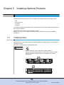
● Chapter 5 Installing Optional Products
This chapter describes how to install optional products.
● Chapter 6 Maintenance
This chapter describes maintenance for the ETERNUS DX60 S2 Disk storage system.
● Chapter 7 Troubleshooting
This chapter explains troubleshooting when errors occur in the ETERNUS DX60 S2 Disk
storage system.
"Event Notification Message List" and "Event (SNMP Trap) Display When Using ServerView
Operation Manager" are described as appendices.
4
ETERNUS DX60 S2 Disk storage system User’s Guide -OperationCopyright 2012 FUJITSU LIMITED
P3AM-5512-03ENZ0
About this Manual
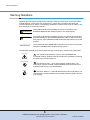
Warning Notations
Warning signs are shown throughout this manual in order to prevent injury to the user and/or
material damage. These signs are composed of a symbol and a message describing the
recommended level of caution. The following explains the symbols, their levels of caution, and
their meanings as used in this manual.
WARNING
CAUTION
IMPORTANT
This symbol indicates the possibility of serious or fatal injury if the
ETERNUS DX60 S2 Disk storage system is not used properly.
This symbol indicates the possibility of minor or moderate personal injury,
as well as damage to the ETERNUS DX60 S2 and/or to other users and
their property, if the ETERNUS DX60 S2 Disk storage system is not used
properly.
This symbol indicates IMPORTANT information for the user to note when
using the ETERNUS DX60 S2 Disk storage system.
The following symbols are used to indicate the type of warnings or cautions being described.
Electric Shock
No Disassembly
Unplug
The triangle emphasizes the urgency of the WARNING and
CAUTION contents. Inside the triangle and above it are details concerning
the symbol (e.g. Electrical Shock).
The barred "Do Not..." circle warns against certain actions. The
action which must be avoided is both illustrated inside the barred circle
and written above it (e.g. No Disassembly).
The black "Must Do..." disk indicates actions that must be taken. The
required action is both illustrated inside the black disk and written above it
(e.g. Unplug).
5
ETERNUS DX60 S2 Disk storage system User’s Guide -OperationCopyright 2012 FUJITSU LIMITED
P3AM-5512-03ENZ0
About this Manual
How Warnings are Presented in this Manual
A message is written beside the symbol indicating the caution level. This message is marked
with a vertical ribbon in the left margin, to distinguish this warning from ordinary descriptions.
An example is shown here.
Warning Level Indicator
Example Warning
Warning Type Indicator
Warning Details
To avoid damaging the ETERNUS DX60 S2 Disk storage system,
pay attention to the following points when cleaning
the ETERNUS DX60 S2 Disk storage system:
- Make sure to disconnect the power when cleaning.
- Be careful that no liquid seeps into the ETERNUS DX60 S2
Disk storage system when using cleaners, etc.
- Do not use alcohol or other solvents to clean
the ETERNUS DX60 S2 Disk storage system.
Warning Layout Ribbon
Additional Information
Symbols Used in This Manual
The following is an expression used throughout this manual:
Functions and know how which can be useful when setting up or operating
the ETERNUS DX60 S2 Disk storage system.
Abbreviations Used in This Manual
• "ETERNUS DX Disk storage system" refers to the ETERNUS DX60 S2 Disk storage system.
• "Host Bus Adapter (HBA)" refers to the interface module normally used by the server to
connect to the ETERNUS DX Disk storage systems.
"Interface module" may be referred to as "FC card", "LAN card", "Network Interface Card
(NIC)", or "SAS card", depending on the type of server and interface that are used.
• Trademark symbols such as ™ and ® are omitted in this document.
6
ETERNUS DX60 S2 Disk storage system User’s Guide -OperationCopyright 2012 FUJITSU LIMITED
P3AM-5512-03ENZ0
Table of Contents
Chapter 1
1.1
1.1.1
1.1.2
1.1.3
1.1.4
1.2
1.2.1
1.2.2
1.2.3
1.2.4
1.3
1.3.1
1.3.2
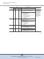
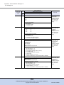
Controller Enclosure ......................................................................................... 12
Front .......................................................................................................................................... 12
Rear ........................................................................................................................................... 13
Components (Front) .................................................................................................................. 13
Components (Rear) ................................................................................................................... 17
Drive Enclosures .............................................................................................. 23
Front .......................................................................................................................................... 23
Rear ........................................................................................................................................... 23
Components (Front) .................................................................................................................. 24
Components (Rear) ................................................................................................................... 26
Power Distribution Units (for Regions other than EMEA&I) ............................. 28
Power Distribution Units (1U) .................................................................................................... 28
Power Distribution Units (2U) .................................................................................................... 29
Chapter 2
2.1
2.1.1
2.1.2
2.1.3
2.2
2.3
2.4
2.5
3.3.1
3.3.2
3.3.3
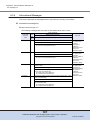
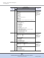
Switching On and Off the Main Line Switch on the Power Distribution Unit
(for Regions Other than EMEA&I) ............................................................................................. 30
Powering On .............................................................................................................................. 32
Powering Off .............................................................................................................................. 34
Attaching and Removing the Flange Cover ..................................................... 35
Attaching and Removing the Front Cover ........................................................ 37
Turning On and Off the AUTO POWER Switch ............................................... 39
Using the IP RESET Switch ............................................................................. 41
Setup .......................................................................................43
Data Encryption ................................................................................................ 43
Eco-mode ......................................................................................................... 43
Optimizing Volume Configurations ................................................................... 46
RAID Migration .......................................................................................................................... 47
Logical Device Expansion (LDE) ............................................................................................... 47
LUN Concatenation ................................................................................................................... 48
Chapter 4
4.1
Standard Operations..............................................................30
Powering On and Off ........................................................................................ 30
Chapter 3
3.1
3.2
3.3
Components ...........................................................................12
Operations ..............................................................................50
LAN for Operation Management ...................................................................... 50
7
ETERNUS DX60 S2 Disk storage system User’s Guide -OperationCopyright 2012 FUJITSU LIMITED
P3AM-5512-03ENZ0
Table of Contents
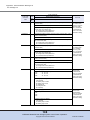
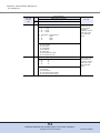
4.2
4.2.1
4.2.2
4.2.3
Monitoring ETERNUS DX Disk Storage System Status .................................. 51
LED Status Check ..................................................................................................................... 52
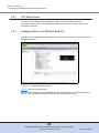
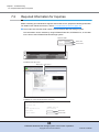
Displaying Status via ETERNUS Web GUI ............................................................................... 52
Event Notification ....................................................................................................................... 53
Chapter 5
5.1
5.1.1
5.1.2
5.1.3
5.1.4
5.2
5.2.1
5.2.2
5.2.3
5.2.4
5.2.5
Installing Disks ................................................................................................. 55
Installation Rules for Disks ........................................................................................................ 56
Installable Disks ......................................................................................................................... 57
Disk Handling Instructions ......................................................................................................... 58
Additional Disk Installation Procedure ....................................................................................... 60
Installing Drive Enclosures ............................................................................... 64
Installation Rules for Drive Enclosures ...................................................................................... 64
Installable Drive Enclosures ...................................................................................................... 64
Drive Enclosure Handling Instructions ....................................................................................... 65
Drive Enclosure Rack Installation Procedure ............................................................................ 66
Additional Drive Enclosure Installation ...................................................................................... 71
Chapter 6
6.1
6.2
6.3
6.4
6.4.1
6.4.2
Maintenance............................................................................77
Periodic Backup ............................................................................................... 77
Volume Formatting Time .................................................................................. 77
Rebuild/Copyback Process Time ..................................................................... 78
Maintenance Service ........................................................................................ 79
Maintenance Support Period ..................................................................................................... 79
Related Service ......................................................................................................................... 79
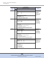
Chapter 7
7.1
7.2
Installing Optional Products .................................................55
Troubleshooting .....................................................................80
Check List ........................................................................................................ 80
Required Information for Inquiries .................................................................... 85
Appendix A Event Notification Message List ...........................................87
A.1
A.1.1
A.1.2
A.1.3
A.2
A.2.1
A.2.2
A.2.3
A.2.4
A.2.5
A.2.6
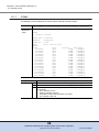
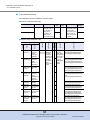
Message Format ............................................................................................... 87
E-Mail ........................................................................................................................................ 88
SNMP ........................................................................................................................................ 90
Host Sense ................................................................................................................................ 92
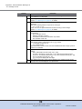
Message List ..................................................................................................... 93
Common Terms......................................................................................................................... 93
Error Messages ......................................................................................................................... 94
Warning Messages.................................................................................................................. 102
Informational Messages .......................................................................................................... 107
Test Messages ........................................................................................................................ 116
Sense Codes ........................................................................................................................... 116
8
ETERNUS DX60 S2 Disk storage system User’s Guide -OperationCopyright 2012 FUJITSU LIMITED
P3AM-5512-03ENZ0
Table of Contents
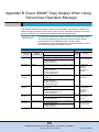
Appendix B Event (SNMP Trap) Display
When Using ServerView Operation Manager ....................119
9
ETERNUS DX60 S2 Disk storage system User’s Guide -OperationCopyright 2012 FUJITSU LIMITED
P3AM-5512-03ENZ0
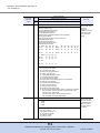
List of Figures
Figure 1.1
Figure 1.2
Figure 1.3
Figure 1.4
Figure 1.5
Figure 1.6
Figure 1.7
Figure 1.8
Figure 1.9
Figure 1.10
Figure 1.11
Figure 1.12
Figure 1.13
Figure 1.14
Figure 1.15
Figure 1.16
Figure 1.17
Figure 1.18
Figure 1.19
Figure 1.20
Figure 1.21
Figure 1.22
Figure 1.23
Figure 1.24
Figure 1.25
Figure 1.26
Figure 1.27
Figure 2.1
Figure 2.2
Figure 2.3
Figure 2.4
Figure 4.1
Figure 4.2
Figure 4.3
Figure 4.4
Figure 5.1
Figure 5.2
Front view of a 2.5" type controller enclosure............................................................................
Front view of a 3.5" type controller enclosure (with front cover)................................................
Front view of a 3.5" type controller enclosure (without front cover)...........................................
Rear view of a controller enclosure (single controller type).......................................................
Rear view of a controller enclosure (dual controller type) .........................................................
Operation panel (2.5" type controller enclosure) .......................................................................
Operation panel (3.5" type controller enclosure) .......................................................................
2.5" type disk .............................................................................................................................
Disk slot numbers (2.5" type controller enclosure) ....................................................................
3.5" type disk .............................................................................................................................
Disk slot numbers (3.5" type controller enclosure) ....................................................................
Controller (FC model) ................................................................................................................
Controller (iSCSI model)............................................................................................................
Controller (SAS model)..............................................................................................................
Power supply unit ......................................................................................................................
Front view of a drive enclosure (with front cover)......................................................................
Front view of a drive enclosure (without front cover).................................................................
Rear view of drive enclosure (single expander model)..............................................................
Rear view of drive enclosure (dual expander model) ................................................................
LEDs on the front side of the drive enclosure............................................................................
3.5" disk .....................................................................................................................................
Disk slot numbers (drive enclosure) ..........................................................................................
Expander ...................................................................................................................................
Power supply units ....................................................................................................................
Power distribution unit (1U) .......................................................................................................
Power Distribution Units (2U, Max 6 enclosures connection)....................................................
Power Distribution Units (2U, Max 8 enclosures connection)....................................................
ON position (marked "|") of the main line switches on a 1U power distribution unit ..................
ON position (marked "|") of the main line switches on a 2U power distribution unit ..................
OFF position (marked "O") of the main line switches on a 1U power distribution unit ..............
OFF position (marked "O") of the main line switches on a 2U power distribution unit ..............
LAN control (switching of the Master CM) .................................................................................
LAN control (when the IP address of the Slave CM is set)........................................................
ETERNUS Web GUI screen......................................................................................................
Event notification .......................................................................................................................
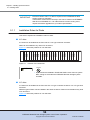
Position of 2.5" disk slots...........................................................................................................
Position of 3.5" disk slots...........................................................................................................
12
12
12
13
13
14
14
15
15
16
16
17
19
20
22
23
23
23
24
24
25
25
26
27
28
29
29
30
31
31
32
50
51
52
54
56
57
10
ETERNUS DX60 S2 Disk storage system User’s Guide -OperationCopyright 2012 FUJITSU LIMITED
P3AM-5512-03ENZ0
List of Tables
Table 1.1
Table 1.2
Table 1.3
Table 1.4
Table 1.5
Table 1.6
Table 1.7
Table 1.8
Table 1.9
Table 1.10
Table 1.11
Table 4.1
Table 5.1
Table 5.2
Table 5.3
Table 6.1
Table 6.2
Table 6.3
Status and meanings of each LED (operation panel (controller enclosure)) .............................
Status and meanings of each LED (2.5" disks) .........................................................................
Status and meanings of each LED (3.5" disks) .........................................................................
Status and meanings of each LED (FC model controller) .........................................................
Status and meanings of each LED (iSCSI model controller) .....................................................
Status and meanings of each LED (SAS model controller).......................................................
Status and meanings of each LED (power supply unit).............................................................
Status and meanings of each LED (in front of drive enclosure) ................................................
Status and meanings of each LED (3.5" disks) .........................................................................
Status and meanings of each LED (expander)..........................................................................
Status and meanings of each LED (power supply unit).............................................................
General status of ETERNUS Web GUI .....................................................................................
Installable disks (2.5" disks) ......................................................................................................
Installable disks (3.5" disks) ......................................................................................................
Installable drive enclosures .......................................................................................................
Time for volume formatting (disk) ..............................................................................................
Rebuild process time (disk) .......................................................................................................
Copyback process time (disk) ...................................................................................................
15
16
17
18
19
21
22
25
25
26
27
53
57
57
64
77
78
78
11
ETERNUS DX60 S2 Disk storage system User’s Guide -OperationCopyright 2012 FUJITSU LIMITED
P3AM-5512-03ENZ0
Chapter 1
Components
This chapter describes the components of the ETERNUS DX Disk storage system.
1.1
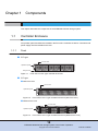
Controller Enclosure
An operation panel and disks are installed in the front of the controller enclosure. Controllers and
power supply units are installed in the rear.
1.1.1
Front
■ 2.5" type
2.5-inch disk
Operation panel
Flange cover
Figure 1.1
Front view of a 2.5" type controller enclosure
■ 3.5" type
● With front cover
Front cover
Operation panel
Figure 1.2
Front view of a 3.5" type controller enclosure (with front cover)
● Without front cover
3.5-inch disk
Operation panel
Figure 1.3
Front view of a 3.5" type controller enclosure (without front cover)
12
ETERNUS DX60 S2 Disk storage system User’s Guide -OperationCopyright 2012 FUJITSU LIMITED
P3AM-5512-03ENZ0
Chapter 1 Components
1.1 Controller Enclosure
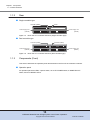
1.1.2
Rear
■ Single controller type
Cover
Controller (CM#0)
Power Supply Unit
(PSU#0)
Figure 1.4
Power Supply Unit
(PSU#1)
Rear view of a controller enclosure (single controller type)
■ Dual controller type
Controller (CM#1)
Controller (CM#0)
Power Supply Unit
(PSU#1)
Power Supply Unit
(PSU#0)
Figure 1.5
1.1.3
Rear view of a controller enclosure (dual controller type)
Components (Front)
This section describes the operation panel and the disks in the front of the controller enclosure.
■ Operation panel
An operation panel has LEDs, a power switch, an AUTO POWER switch, a MODE SELECT
switch, and an IP RESET switch.
13
ETERNUS DX60 S2 Disk storage system User’s Guide -OperationCopyright 2012 FUJITSU LIMITED
P3AM-5512-03ENZ0
Chapter 1 Components
1.1 Controller Enclosure
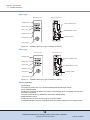
● 2.5" type
With a flange cover
Without a flange cover
POWER LED
AUTO POWER switch
READY LED
FAULT LED
MODE SELECT switch
IDENTIFY LED
IP RESET switch
CACHE LED
Power switch
Figure 1.6
Operation panel (2.5" type controller enclosure)
● 3.5" type
With a front cover
Without a front cover
POWER LED
AUTO POWER switch
READY LED
FAULT LED
MODE SELECT switch
IDENTIFY LED
IP RESET switch
CACHE LED
Power switch
Figure 1.7
Operation panel (3.5" type controller enclosure)
● Part explanation
• Power switch
This switch is used to turn on or off the ETERNUS DX Disk storage system.
• AUTO POWER switch
Enables the AC Auto-Link Mode (This function automatically turns on the linked device once
AC power is supplied).
The Auto Power function is disabled for the factory default setting.
• MODE SELECT switch
Enables the device power to be turned on via power linkage.
The MODE SELECT switch is enabled for the factory default setting. Do not change to OFF.
14
ETERNUS DX60 S2 Disk storage system User’s Guide -OperationCopyright 2012 FUJITSU LIMITED
P3AM-5512-03ENZ0
Chapter 1 Components
1.1 Controller Enclosure
• IP RESET switch
Click once to switch the Master CM LAN port from the current controller to the other controller.
Click twice in succession within a two second interval to revert the LAN port settings of the
ETERNUS DX Disk storage system to their factory settings.
• LEDs
The states of LEDs are listed below.
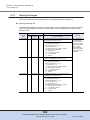
Table 1.1
Status and meanings of each LED (operation panel (controller enclosure))
LED name
LED status
ETERNUS DX Disk storage system status
POWER
DC power is supplied to the controller enclosure.
(green)
READY
(green)
The ETERNUS DX Disk storage system is available for
use.
(orange)
The ETERNUS DX Disk storage system is in error
status.
(blinks orange)
A part of the ETERNUS DX Disk storage system
requires preventive maintenance.
(blinks blue)
As ordered via ETERNUS Web GUI, the installation
location of the controller enclosure is identified.
(green)
There is data in the ETERNUS DX Disk storage system
cache memory.
(blinks green)
Data in the cache memory is saved to a non-volatile
memory.
FAULT
IDENTIFY
CACHE
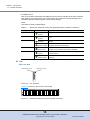
■ Disk
● For 2.5" Disk
DISK READY LED
Figure 1.8
DISK FAULT LED
2.5" type disk
Figure 1.9
Slot#16
Slot#17
Slot#18
Slot#19
Slot#20
Slot#21
Slot#22
Slot#23
Slot#8
Slot#9
Slot#10
Slot#11
Slot#12
Slot#13
Slot#14
Slot#15
Slot#0
Slot#1
Slot#2
Slot#3
Slot#4
Slot#5
Slot#6
Slot#7
Figure 1.9 shows the slot number of each disk.
Disk slot numbers (2.5" type controller enclosure)
15
ETERNUS DX60 S2 Disk storage system User’s Guide -OperationCopyright 2012 FUJITSU LIMITED
P3AM-5512-03ENZ0
Chapter 1 Components
1.1 Controller Enclosure
Do Not
WARNING
• System disks are installed in Slot#0 and Slot#1. Never remove
system disks. Doing so will render the ETERNUS DX Disk storage
system unusable.
● Part explanation
• LEDs
The states of LEDs are listed below.
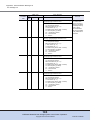
Table 1.2
Status and meanings of each LED (2.5" disks)
LED name
LED status
DISK READY
Disk status
The disk is operating normally.
(green)
(blinks green)
The disk is in error status.
DISK FAULT
(orange)
● For 3.5" Disks
DISK READY/FAULT LED
Figure 1.10 3.5" type disk
Figure 1.11 shows the slot number of each disk.
Slot#8
Slot#9
Slot#10
Slot#11
Slot#4
Slot#5
Slot#6
Slot#7
Slot#0
Slot#1
Slot#2
Slot#3
Figure 1.11 Disk slot numbers (3.5" type controller enclosure)
Do Not
WARNING
• System disks are installed in Slot#0 and Slot#1. Never remove
system disks. Doing so will render the ETERNUS DX Disk storage
system unusable.
● Part explanation
• LEDs
The states of LEDs are listed below.
16
ETERNUS DX60 S2 Disk storage system User’s Guide -OperationCopyright 2012 FUJITSU LIMITED
P3AM-5512-03ENZ0
Chapter 1 Components
1.1 Controller Enclosure
Table 1.3
Status and meanings of each LED (3.5" disks)
LED name
LED status
DISK READY/
FAULT
Disk status
The disk is operating normally.
(green)
(blinks green)
The disk is in error status.
(orange)
1.1.4
Components (Rear)
This section describes the controllers and the power supply units in the rear of the controller
enclosure.
1.1.4.1
Controllers
The controller contains a CPU, cache memory, System Capacitor Unit (SCU), non-volatile memory, host interface adapters, drive interface (DI) ports, and LAN ports.
The controller controls all operations in the ETERNUS DX Disk storage system.
■ FC model
SCU STATUS LED
IDENTIFY LED
DI (OUT) LINKUP LED
LAN (RMT) port
LAN (MNT) port
FC LINKUP/FAULT LED
FC port (0 (Left), 1 (Right))
UNIT READY/FAULT LED
MASTER LED
PWC port
ACT LED
LINK LED
DI (OUT) port
Figure 1.12 Controller (FC model)
● Part explanation
• LAN (RMT) port, LAN (MNT) port
These are the RJ-45 connectors to connect LAN cables. LAN (RMT) port is not used in the
EMEA&I region.
A single controller has one LAN (RMT) port and one LAN (MNT) port.
• FC port (0 (left), 1 (right))
These are the Dual LC connectors to connect FC cables.
17
ETERNUS DX60 S2 Disk storage system User’s Guide -OperationCopyright 2012 FUJITSU LIMITED
P3AM-5512-03ENZ0
Chapter 1 Components
1.1 Controller Enclosure
• PWC port
This port is used for power synchronization.
• DI (OUT) port
This port is used to connect a controller enclosure to a drive enclosure with a miniSAS cable.
• LEDs
The states of LEDs are listed below.
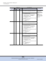
Table 1.4
Status and meanings of each LED (FC model controller)
LED name
LED status
SCU STATUS
Controller status
The SCU is in normal status.
(green)
SCU is charging.
(blinks green)
IDENTIFY
(blinks blue)
As ordered via ETERNUS Web GUI, the installation
location of the controller enclosure is identified.
(off)
DI (OUT) LINKUP
FC LINKUP/
FAULT
(green)
The link between the DI (OUT) port and the destination
has been established.
(green)
The link between the FC port (host interface port) and
the destination has been established.
The FC port (host interface port) is in error status.
(orange)
UNIT READY/
FAULT
The controller is in normal status.
(green)
• The controller is performing the initial setup after the
(orange)
power is turned on.
• The controller is in error status.
MASTER
The controller is set as a Master CM.
(green)
ACT
The controller is sending or receiving data via the LAN
port (for operation management).
(green)
LINK
The link between the LAN port (for operation
management) and the destination has been
established.
(green)
18
ETERNUS DX60 S2 Disk storage system User’s Guide -OperationCopyright 2012 FUJITSU LIMITED
P3AM-5512-03ENZ0
Chapter 1 Components
1.1 Controller Enclosure
■ iSCSI model
SCU STATUS LED
IDENTIFY LED
DI (OUT) LINKUP LED
LAN (RMT) port
LAN (MNT) port
iSCSI port (0 (Left), 1 (Right))
UNIT READY/FAULT LED
MASTER LED
PWC port
FAULT LED
LINK LED
ACT LED
LINK LED
DI (OUT) port
Figure 1.13 Controller (iSCSI model)
● Part explanation
• LAN (RMT) port, LAN (MNT) port
These are the RJ-45 connectors to connect LAN cables. LAN (RMT) port is not used in the
EMEA&I region.
A single controller has one LAN (RMT) port and one LAN (MNT) port.
• iSCSI port (0 (left), 1 (right))
These ports are RJ45 connectors for LAN cables.
• PWC port
This port is used for power synchronization.
• DI (OUT) port
This port is used to connect a controller enclosure to a drive enclosure with a miniSAS cable.
• LEDs
The states of LEDs are listed below.
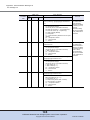
Table 1.5
Status and meanings of each LED (iSCSI model controller)
LED name
LED status
SCU STATUS
Controller status
The SCU is in normal status.
(green)
SCU is charging.
(blinks green)
IDENTIFY
(blinks blue)
As ordered via ETERNUS Web GUI, the installation
location of the controller enclosure is identified.
(off)
DI (OUT) LINKUP
The link between the DI (OUT) port and the destination
has been established.
(green)
19
ETERNUS DX60 S2 Disk storage system User’s Guide -OperationCopyright 2012 FUJITSU LIMITED
P3AM-5512-03ENZ0
Chapter 1 Components
1.1 Controller Enclosure
LED name
UNIT READY/
FAULT
LED status
Controller status
The controller is in normal status.
(green)
• The controller is performing the initial setup after the
(orange)
power is turned on.
• The controller is in error status.
MASTER
The controller is set as a Master CM.
(green)
ACT
The controller is sending or receiving data via the LAN
port (for operation management).
(green)
LINK
• The link between the LAN port (for operation
(green)
management) and the destination has been
established.
• The link between the iSCSI port (host interface port)
and the destination has been established.
FAULT
• The controller is performing the initial setup after the
(orange)
power is turned on.
• The iSCSI port (host interface port) is in error status.
■ SAS model
SCU STATUS LED
IDENTIFY LED
DI (OUT) LINKUP LED
LAN (RMT) port
LAN (MNT) port
SAS (HOST) LINKUP/FAULT LED
SAS port (0 (Left), 1 (Right))
UNIT READY/FAULT LED
MASTER LED
PWC port
ACT LED
LINK LED
DI (OUT) port
Figure 1.14 Controller (SAS model)
● Part explanation
• LAN (RMT) port, LAN (MNT) port
These are the RJ-45 connectors to connect LAN cables. LAN (RMT) port is not used in the
EMEA&I region.
A single controller has one LAN (RMT) port and one LAN (MNT) port.
• SAS port (0 (left), 1 (right))
These are the miniSAS (SFF8088) connectors to connect miniSAS cables.
20
ETERNUS DX60 S2 Disk storage system User’s Guide -OperationCopyright 2012 FUJITSU LIMITED
P3AM-5512-03ENZ0
Chapter 1 Components
1.1 Controller Enclosure
• PWC port
This port is used for power synchronization.
• DI (OUT) port
This port is used to connect a controller enclosure to a drive enclosure with a miniSAS cable.
• LEDs
The states of LEDs are listed below.
Table 1.6
Status and meanings of each LED (SAS model controller)
LED name
LED status
SCU STATUS
Controller status
The SCU is in normal status.
(green)
SCU is charging.
(blinks green)
IDENTIFY
(blinks blue)
As ordered via ETERNUS Web GUI, the installation
location of the controller enclosure is identified.
(off)
DI (OUT) LINKUP
SAS (HOST)
LINKUP/FAULT
(green)
The link between the DI (OUT) port and the destination
has been established.
(green)
The link between the SAS port (host interface port) and
the destination has been established.
The SAS port (host interface port) is in error status.
(orange)
UNIT READY/
FAULT
The controller is in normal status.
(green)
• The controller is performing the initial setup after the
(orange)
power is turned on.
• The controller is in error status.
MASTER
The controller is set as a Master CM.
(green)
ACT
The controller is sending or receiving data via the LAN
port (for operation management).
(green)
LINK
The link between the LAN port (for operation
management) and the destination has been
established.
(green)
■ System Capacitor Unit (SCU)
A SCU is installed in a controller as a backup power source in case of power outage.
The SCU is charged from an external power source while the ETERNUS DX Disk storage
system is running normally. If a power outage is detected, data in the cache memory is saved to
a non-volatile memory in the controller using the SCU. The saved data is retained in the nonvolatile memory indefinitely.
21
ETERNUS DX60 S2 Disk storage system User’s Guide -OperationCopyright 2012 FUJITSU LIMITED
P3AM-5512-03ENZ0
Chapter 1 Components
1.1 Controller Enclosure
1.1.4.2
Power Supply Units
The power supply unit transforms input AC power from a power socket to DC power and supplies
power to each component.
Each power supply unit contains fans.
Inlet
STATUS LED
Figure 1.15 Power supply unit
● Part explanation
• Inlet
This inlet is used to connect a power cord.
• LEDs
The states of LEDs are listed below.
Table 1.7
Status and meanings of each LED (power supply unit)
LED name
LED status
STATUS
Power supply unit status
(green)
AC power is supplied to the power supply unit and the
ETERNUS DX Disk storage system (DC power) is
turned on.
(blinks green)
AC power is supplied to the power supply unit but the
ETERNUS DX Disk storage system (DC power) is not
turned on.
The power supply unit or the fan in the power supply
unit is in error status.
(orange)
22
ETERNUS DX60 S2 Disk storage system User’s Guide -OperationCopyright 2012 FUJITSU LIMITED
P3AM-5512-03ENZ0
Chapter 1 Components
1.2 Drive Enclosures
1.2
Drive Enclosures
3.5" disks and LEDs are installed in the front of a 3.5" drive enclosure. Expanders and power
supply units are installed in the rear.
1.2.1
Front
● With front cover
Front cover
Operation panel
Figure 1.16 Front view of a drive enclosure (with front cover)
● Without front cover
3.5-inch disk
Operation panel
Figure 1.17 Front view of a drive enclosure (without front cover)
1.2.2
Rear
■ Single expander type
Expander (EXP#0)
Cover
Power Supply Unit
(PSU#0)
Power Supply Unit
(PSU#1)
Figure 1.18 Rear view of drive enclosure (single expander model)
23
ETERNUS DX60 S2 Disk storage system User’s Guide -OperationCopyright 2012 FUJITSU LIMITED
P3AM-5512-03ENZ0
Chapter 1 Components
1.2 Drive Enclosures
■ Dual expander type
Expander (EXP#0)
Expander (EXP#1)
Power Supply Unit
(PSU#0)
Power Supply Unit
(PSU#1)
Figure 1.19 Rear view of drive enclosure (dual expander model)
1.2.3
Components (Front)
This section describes the operation panel and the disks in the front of the drive enclosure.
■ Operation panel
An operation panel has LEDs, an AUTO POWER switch, a MODE SELECT switch, and an IP
RESET switch.
With a front cover
Without a front cover
POWER LED
READY LED
AUTO POWER switch
FAULT LED
MODE SELECT switch
IDENTIFY LED
This switch is not used.
Figure 1.20 LEDs on the front side of the drive enclosure
● Part explanation
• AUTO POWER switch
The AUTO POWER switch of the drive enclosure is turned to "OFF" as the factory setting,
and should not be turned to "ON".
• MODE SELECT switch
Enables the device power to be turned on via power linkage.
The MODE SELECT switch is enabled for the factory default setting. Do not change to OFF.
• LEDs
The states of LEDs are listed below.
24
ETERNUS DX60 S2 Disk storage system User’s Guide -OperationCopyright 2012 FUJITSU LIMITED
P3AM-5512-03ENZ0
Chapter 1 Components
1.2 Drive Enclosures
Table 1.8
Status and meanings of each LED (in front of drive enclosure)
LED name
LED status
POWER
Drive enclosure status
DC power is supplied to the drive enclosure.
(green)
READY
The ETERNUS DX Disk storage system is available for
use.
(green)
FAULT
The drive enclosure is in error status.
(orange)
(blinks orange)
A part of the drive enclosure requires preventive
maintenance.
(blinks blue)
As ordered via ETERNUS Web GUI, the installation
location of the drive enclosure is identified.
IDENTIFY
(off)
■ Disk
DISK READY/FAULT LED
Figure 1.21 3.5" disk
Figure 1.22 shows the slot number of each disk.
Slot#8
Slot#9
Slot#10
Slot#11
Slot#4
Slot#5
Slot#6
Slot#7
Slot#0
Slot#1
Slot#2
Slot#3
Figure 1.22 Disk slot numbers (drive enclosure)
● Part explanation
• LEDs
The states of LEDs are listed below.
Table 1.9
Status and meanings of each LED (3.5" disks)
LED name
DISK READY/
FAULT
LED status
Disk status
The disk is operating normally.
(green)
(blinks green)
The disk is in error status.
(orange)
25
ETERNUS DX60 S2 Disk storage system User’s Guide -OperationCopyright 2012 FUJITSU LIMITED
P3AM-5512-03ENZ0
Chapter 1 Components
1.2 Drive Enclosures
1.2.4
Components (Rear)
This section describes the expanders and the power supply units in the rear of the drive enclosure.
■ Expander
The expander is a component that controls how the controller and the disks interact.
IDENTIFY LED
DI (IN) LINKUP LED
UNIT READY/FAULT LED
DI (IN) port
These ports are not used.
Figure 1.23 Expander
● Part explanation
• DI (IN) port
These ports are connectors for miniSAS cables.
• LEDs
The states of LEDs are listed below.
Table 1.10
Status and meanings of each LED (expander)
LED name
LED status
IDENTIFY
(blinks blue)
Expander status
As ordered via ETERNUS Web GUI, the installation
location of the drive enclosure is identified.
(off)
DI (IN) LINKUP
LED
The link between the DI (IN) port and the destination
has been established.
(green)
The DI (IN) port is in error status.
(orange)
UNIT READY/
FAULT
The expander is in normal status.
(green)
• The controller is performing the initial setup after the
(orange)
power is turned on.
• The expander is in error status.
26
ETERNUS DX60 S2 Disk storage system User’s Guide -OperationCopyright 2012 FUJITSU LIMITED
P3AM-5512-03ENZ0
Chapter 1 Components
1.2 Drive Enclosures
■ Power Supply Units
The power supply unit transforms input AC power from a power socket to DC power and supplies
power to each component.
Each power supply unit contains fans.
Inlet
STATUS LED
Figure 1.24 Power supply units
● Part explanation
• Inlet
This inlet is used to connect a power cord.
• LEDs
The states of LEDs are listed below.
Table 1.11
Status and meanings of each LED (power supply unit)
LED name
LED status
STATUS
Power supply unit status
(green)
AC power is supplied to the power supply unit and the
ETERNUS DX Disk storage system (DC power) is
turned on.
(blinks green)
AC power is supplied to the power supply unit but the
ETERNUS DX Disk storage system (DC power) is not
turned on.
The power supply unit or the fan in the power supply
unit is in error status.
(orange)
27
ETERNUS DX60 S2 Disk storage system User’s Guide -OperationCopyright 2012 FUJITSU LIMITED
P3AM-5512-03ENZ0
Chapter 1 Components
1.3 Power Distribution Units (for Regions other than EMEA&I)
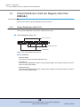
1.3
Power Distribution Units (for Regions other than
EMEA&I)
There are two sizes for power distribution units: 1U and 2U.
1.3.1
Power Distribution Units (1U)
The 1U power distribution unit has four outlets and two inlets.
■ Power Distribution Units (1U)
Main line switches
Outlets (OUTPUT)
Inlets (INPUT)
Figure 1.25 Power distribution unit (1U)
● Part explanation
• Main line switch
This turns on and off the power distribution unit.
• Inlet (INPUT)
This is a socket (IEC60320-C13) for incoming power supply. This socket is used to connect a
power cord (AC input cable).
• Outlet (OUTPUT)
This is a socket (IEC60320-C13) for outgoing power supply. This socket is used to connect a
power cord (AC output cable).
28
ETERNUS DX60 S2 Disk storage system User’s Guide -OperationCopyright 2012 FUJITSU LIMITED
P3AM-5512-03ENZ0
Chapter 1 Components
1.3 Power Distribution Units (for Regions other than EMEA&I)
1.3.2
Power Distribution Units (2U)
There are two types of 2U power distribution units: 2U power distribution units that can connect
up to six enclosures and 2U power distribution units that can connect up to eight enclosures.
■ Power Distribution Units (2U, Max 6 enclosures connection)
There are 12 outlets.
Main line switches
Outlets (OUTPUT)
Figure 1.26 Power Distribution Units (2U, Max 6 enclosures connection)
● Part explanation
• Main line switch
This turns on and off the power distribution unit.
• Outlet (OUTPUT)
This is a socket (IEC60320-C13) for outgoing power supply. This socket is used to connect a
power cord (AC output cable).
■ Power Distribution Units (2U, Max 8 enclosures connection)
There are 16 outlets.
Main line switches
Outlets (OUTPUT)
Figure 1.27 Power Distribution Units (2U, Max 8 enclosures connection)
● Part explanation
• Main line switch
This turns on and off the power distribution unit.
• Outlet (OUTPUT)
This is a socket (IEC60320-C13) for outgoing power supply. This socket is used to connect a
power cord (AC output cable).
29
ETERNUS DX60 S2 Disk storage system User’s Guide -OperationCopyright 2012 FUJITSU LIMITED
P3AM-5512-03ENZ0
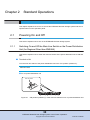
Chapter 2
Standard Operations
This chapter explains how to turn on and off the ETERNUS DX Disk storage system and how to
operate buttons on the operation panel.
2.1
Powering On and Off
This section explains how to turn on the ETERNUS DX Disk storage system.
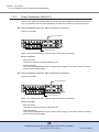
2.1.1
Switching On and Off the Main Line Switch on the Power Distribution
Unit (for Regions Other than EMEA&I)
This section explains how to switch the main line switch of the power distribution unit to ON and
OFF.
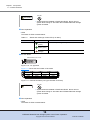
■ To switch to ON
Turn the main line switch of the power distribution unit to the "On" position (marked "I").
IMPORTANT
Make sure all of the main line switches are in the ON position.
● For 1U power distribution unit
Main line switch
Figure 2.1
ON position (marked "|") of the main line switches on a 1U power distribution unit
30
ETERNUS DX60 S2 Disk storage system User’s Guide -OperationCopyright 2012 FUJITSU LIMITED
P3AM-5512-03ENZ0
Chapter 2 Standard Operations
2.1 Powering On and Off
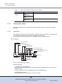
● For 2U power distribution unit
Main line switch
Figure 2.2
ON position (marked "|") of the main line switches on a 2U power distribution unit
■ To switch to OFF
Turn the main line switch of the power distribution unit to the "Off" position (marked "O").
For normal operation, there is no need to the turn the main line switch to
the "Off" position. If the ETERNUS DX Disk storage system must be turned
off, such as before any inspections of power supply devices are performed,
turn off the ETERNUS DX Disk storage system by using the procedure
described in "2.1.3 Powering Off" (page 34) and turn the main line to the
"Off" position.
● For 1U power distribution unit
Main line switch
Figure 2.3
OFF position (marked "O") of the main line switches on a 1U power distribution
unit
31
ETERNUS DX60 S2 Disk storage system User’s Guide -OperationCopyright 2012 FUJITSU LIMITED
P3AM-5512-03ENZ0
Chapter 2 Standard Operations
2.1 Powering On and Off
● For 2U power distribution unit
Main line switch
Figure 2.4
OFF position (marked "O") of the main line switches on a 2U power distribution
unit
IMPORTANT
2.1.2
When turning the main line switch to "On" (marked "I") right after turning the
main line switch to "Off" (marked "O"), turn it back to "On" (marked "I") after
the POWER LED of the power supply unit has turned off completely.
Powering On
This section explains how to turn on the ETERNUS DX Disk storage system.
There are two ways to turn the power on:
• Via the Power switch
Press the Power switch to turn on the ETERNUS DX Disk storage system.
• Via the power synchronized unit
Use the power synchronized unit to turn on the ETERNUS DX Disk storage system.
Before turning on the ETERNUS DX Disk storage system, make sure that
the main line switches of the power distribution units are "ON".
Do not turn the main line switches of the power distribution units to the OFF
position.
32
ETERNUS DX60 S2 Disk storage system User’s Guide -OperationCopyright 2012 FUJITSU LIMITED
P3AM-5512-03ENZ0
Chapter 2 Standard Operations
2.1 Powering On and Off
IMPORTANT
• After turning the power on, it takes about three minutes for the
ETERNUS DX Disk storage system to become READY (i.e. the READY
LED turns on). If an error is detected during the initial power-on
diagnostic phase, a longer time (up to ten minutes) may be required
before the READY LED turns on.
• Before turning the server on, check that the ETERNUS DX Disk storage
system and the network devices that connect the ETERNUS DX Disk
storage system and the server are all in READY status. If the server is
turned on while any of these devices are not in READY status, the
server may not be able to recognize the ETERNUS DX Disk storage
system.
• When turning on the power in conjunction with the power synchronized
unit, perform the appropriate waiting process so that the ETERNUS DX
Disk storage system is in the READY status before the server is turned
on. Since it takes up to ten minutes before the ETERNUS DX Disk
storage system change to READY status when an error is detected for a
component during the initial power-on diagnostic phase, take this into
consideration and specify an appropriate waiting process that is
sufficient.
• When the AUTO POWER switch of the controller enclosure is turned to
"ON", supplying power to the ETERNUS DX Disk storage system will
cause the ETERNUS DX Disk storage system to turn on automatically in
cases such as when the power cord is connected or the power is
recovered after power failure.
This section explains how to use the Power switch to turn on the ETERNUS DX Disk storage
system. For other procedures, refer to the related manuals.
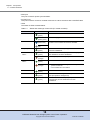
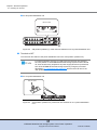
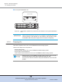
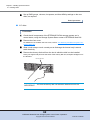
Procedure
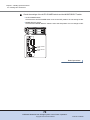
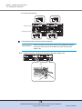
1
Press the power switch ( ) of the controller enclosure.
Controller enclosure POWER LED turns on.
When drive enclosures are installed, the power turns on
automatically.
Power switch
Drive Enclosure
Controller Enclosure
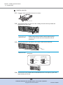
2
After three minutes, check that the READY LED on the controller enclosure are
lit up.
33
ETERNUS DX60 S2 Disk storage system User’s Guide -OperationCopyright 2012 FUJITSU LIMITED
P3AM-5512-03ENZ0
Chapter 2 Standard Operations
2.1 Powering On and Off
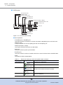
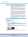
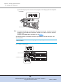
3
Check that all enclosure's POWER LED and READY LED are lit up.
LED for drive enclosure
Drive enclosure
Controller enclosure
LED for controller enclosure
End of procedure
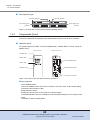
2.1.3
Powering Off
This section explains how to turn off the ETERNUS DX Disk storage system.
There are two ways to turn the power off:
• Via the Power switch
Press the Power switch to turn off the ETERNUS DX Disk storage system.
• Via the power synchronized unit
Use the power synchronized unit to turn off the ETERNUS DX Disk storage system.
IMPORTANT
• When turning off the ETERNUS DX Disk storage system, the power
shuts off after the data in the cache memory is written to the disk.
Therefore, it may take one minute (maximum six minutes) for the power
supply to be completely turned off.
• Do not turn off the power of the device or network devices that connect
the ETERNUS DX Disk storage system and server while the server is
operating. Turning the power off may result in the loss of data or prevent
data from being saved.
• When using a power synchronized unit for power control, make sure to
turn off the power with the server. Even if the ETERNUS DX Disk
storage system is turned off by using the Power switch, the power
synchronization function automatically turns on the power.
This section explains how to use the Power switch to turn off the ETERNUS DX Disk storage
system. For other procedures, refer to the related manuals.
34
ETERNUS DX60 S2 Disk storage system User’s Guide -OperationCopyright 2012 FUJITSU LIMITED
P3AM-5512-03ENZ0
Chapter 2 Standard Operations
2.2 Attaching and Removing the Flange Cover
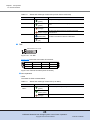
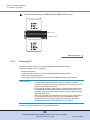
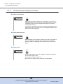
Procedure
1
Press and hold the console panel's power switch ( ) for 4 seconds or longer.
The READY LED should turn off.
IMPORTANT
Press the Power switch only once. If the Power switch is pressed
again while either the POWER LED or the READY LED is on, the
ETERNUS DX Disk storage system power may turn on.
Power switch
Drive Enclosure
Controller Enclosure
2
The ETERNUS DX Disk storage system power is turned off.
When the power is turned off, the POWER LED will go out.
When drive enclosures are installed, the power turns off
automatically.
End of procedure
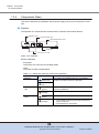
2.2
Attaching and Removing the Flange Cover
This section explains how to attach and remove the flange cover of the 2.5" type controller
enclosure.
Do
CAUTION
• At the completion of this operation, check that the flange cover is
attached.
35
ETERNUS DX60 S2 Disk storage system User’s Guide -OperationCopyright 2012 FUJITSU LIMITED
P3AM-5512-03ENZ0
Chapter 2 Standard Operations
2.2 Attaching and Removing the Flange Cover
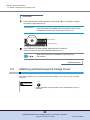
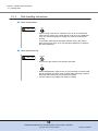
■ Procedure for attaching the flange cover
Attach the flange cover in the following order.
Procedure
1
Slide the tab inside the top of the flange cover over the top-left corner of the
controller enclosure.
IMPORTANT
When fitting the flange cover, be careful not to touch the power
switch (
).
Flange cover
2
Tighten the thumb screw to fasten the flange cover.
Thumb screw
End of procedure
■ Procedure for removing the flange cover
Loosen the thumb screw to remove the flange cover.
36
ETERNUS DX60 S2 Disk storage system User’s Guide -OperationCopyright 2012 FUJITSU LIMITED
P3AM-5512-03ENZ0
Chapter 2 Standard Operations
2.3 Attaching and Removing the Front Cover
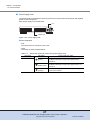
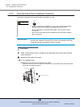
2.3
Attaching and Removing the Front Cover
This section explains how to attach and remove the front cover of the 3.5" type controller
enclosure or 3.5" type drive enclosure.
Do
CAUTION
• After completing the operation, be sure to reattach the front cover.
This section explains how to attach and remove the front cover of the 3.5"
type controller enclosure, but the same procedure is used to attach and
remove the front cover of the 3.5" type drive enclosure.
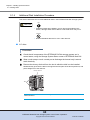
■ Procedure for attaching the front cover
Attach the front cover in the following order.
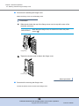
Procedure
1
Fit the front cover in the left end slot of the controller enclosure to attach.
IMPORTANT
Be careful so that the part of the front cover to be fit in the slot does
not touch the power switch (
).
Slot
37
ETERNUS DX60 S2 Disk storage system User’s Guide -OperationCopyright 2012 FUJITSU LIMITED
P3AM-5512-03ENZ0
Chapter 2 Standard Operations
2.3 Attaching and Removing the Front Cover
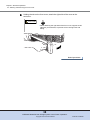
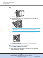
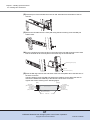
2
Holding the tab on the front cover, attach the right side of the cover to the
enclosure.
Do
CAUTION
• When attaching the right side of the front cover, support its left
side with your left hand, to prevent it from coming loose and
falling.
Tab
End of procedure
38
ETERNUS DX60 S2 Disk storage system User’s Guide -OperationCopyright 2012 FUJITSU LIMITED
P3AM-5512-03ENZ0
Chapter 2 Standard Operations
2.4 Turning On and Off the AUTO POWER Switch
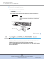
■ Procedure for removing the front cover
Remove the front cover in the following order.
Procedure
1
By holding the tab of the front cover, pull the cover toward you to remove it.
Do
CAUTION
• When removing the right side of the front cover, support its left
side with your left hand, to prevent it from coming loose and
falling.
Tab
End of procedure
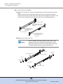
2.4
Turning On and Off the AUTO POWER Switch
This section explains how to enable the AC automatic linkage mode by turning the AUTO
POWER switch of the controller enclosure to "ON".
When AC automatic linkage mode is enabled, the ETERNUS DX Disk storage system is automatically turned on when the power supply recovers after a power failure.
When the AUTO POWER switch of the controller enclosure is set to "OFF", the AC automatic
linkage mode is disabled.
39
ETERNUS DX60 S2 Disk storage system User’s Guide -OperationCopyright 2012 FUJITSU LIMITED
P3AM-5512-03ENZ0
Chapter 2 Standard Operations
2.4 Turning On and Off the AUTO POWER Switch
Procedure
1
Remove the flange cover from the 2.5" type controller enclosure.
Remove the front cover from the 3.5" type controller enclosure.
For details on how to remove the flange cover, refer to "2.2 Attaching and Removing the
Flange Cover" (page 35).
For details on how to remove the front cover, refer to "2.3 Attaching and Removing the
Front Cover" (page 37).
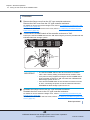
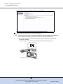
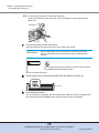
2
Turn the AUTO POWER switch of the controller enclosure to "ON".
Push up the AUTO POWER switch to the "ON" side using the pin that is provided with the
ETERNUS DX Disk storage system.
Pin
AUTO POWER
switch
IMPORTANT
3
• The AUTO POWER switch of the drive enclosure is turned to
"OFF" as the factory setting, and should not be turned to "ON".
• If AC power is being supplied, turning the AUTO POWER switch
of the controller enclosure to "ON" will cause the ETERNUS DX
Disk storage system to turn on.
• If the AUTO POWER switch of the controller enclosure is turned
to "ON", connecting the power cord to the outlet will cause the
ETERNUS DX Disk storage system to turn on.
Re-attach the flange cover to the 2.5" type controller enclosure.
Re-attach the front cover to the 3.5" type controller enclosure.
For details on how to attach the flange cover, refer to "2.2 Attaching and Removing the
Flange Cover" (page 35).
For details on how to attach the front cover, refer to "2.3 Attaching and Removing the Front
Cover" (page 37).
End of procedure
40
ETERNUS DX60 S2 Disk storage system User’s Guide -OperationCopyright 2012 FUJITSU LIMITED
P3AM-5512-03ENZ0
Chapter 2 Standard Operations
2.5 Using the IP RESET Switch
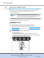
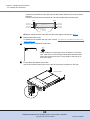
2.5
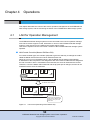
Using the IP RESET Switch
This section describes how to operate the IP RESET switch on the controller enclosure.
The following setting can be performed by operating the IP RESET switch:
• Switching the Master CM
For the dual controller model, the controller through which the
ETERNUS DX Disk storage system is set up and operated is called the
"Master CM", while the other controller is called the "Slave CM". The
single controller model only has a "Master CM" controller.
• Restoring the LAN port settings (network environment settings) to the factory default settings.
The procedure to operate the IP RESET switch is as follows:
Procedure
1
Remove the flange cover from the 2.5" type controller enclosure.
Remove the front cover from the 3.5" type controller enclosure.
For details on how to remove the flange cover, refer to "2.2 Attaching and Removing the
Flange Cover" (page 35).
For details on how to remove the front cover, refer to "2.3 Attaching and Removing the
Front Cover" (page 37).
2
Operate the IP RESET switch to change settings.
• To switch the Master CM
Press the IP RESET switch once.
The MASTER LED on the controller that is set as the Master CM turns green.
• To restore the LAN port settings (network environment settings) to the factory default
Press the IP RESET Switch twice within two seconds.
IP RESET
switch
41
ETERNUS DX60 S2 Disk storage system User’s Guide -OperationCopyright 2012 FUJITSU LIMITED
P3AM-5512-03ENZ0
Chapter 2 Standard Operations
2.5 Using the IP RESET Switch
3
Re-attach the flange cover to the 2.5" type controller enclosure.
Re-attach the front cover to the 3.5" type controller enclosure.
For details on how to attach the flange cover, refer to "2.2 Attaching and Removing the
Flange Cover" (page 35).
For details on how to attach the front cover, refer to "2.3 Attaching and Removing the Front
Cover" (page 37).
End of procedure
42
ETERNUS DX60 S2 Disk storage system User’s Guide -OperationCopyright 2012 FUJITSU LIMITED
P3AM-5512-03ENZ0
Chapter 3
Setup
This chapter describes the required settings for operation of the ETERNUS DX Disk storage
system and provides notes for setting up the ETERNUS DX Disk storage system.
3.1
Data Encryption
Encrypting data as it is being written to the disk prevents information leakage caused by fraudulent decoding.
Even if a disk is removed and stolen by malicious third parties, data cannot be decoded.
The encryption function only encrypts the data stored on the disks, so server access results in
the transmission of plain text. Therefore, this function is effective against leakage of data being
transferred via sneaker net, but has no effect on data leakage via server access.
This section describes the restrictions and notes on encrypting data.
For details on the data encryption procedure, refer to "ETERNUS Web GUI User's Guide" or
"ETERNUS CLI User's Guide".
• Encrypted volumes cannot be changed to unencrypted volumes.
To cancel the encryption for a volume, back up the data in the encrypted volume, delete the
encrypted volume, and restore the backed up data.
• When copying encrypted volumes (using copy operations via server), transfer performance
may not be as good as when copying unencrypted volumes.
• Snap Data Pool Volumes (SDPVs) cannot be encrypted after they are created. To create an
encrypted SDPV, set encryption when creating a volume.
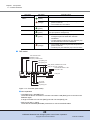
3.2
Eco-mode
Eco-mode is a function that is specifically designed to reduce the power consumption that is
characteristic of Massive Arrays of Idle Disks (MAID). Eco-mode saves power by managing the
scheduled operation times of specified disks and stopping the motors of disks during periods
when they are not required.
Disk spin-up and spin-down schedules can be set for each RAID group, and can also be set to
allow backup operations.
If an access occurs while a motor is stopped, the disk is immediately spun up and access proceeds normally after approximately one to three minutes.
The disk motors can be turned on and off as required by linking the following Storage Foundation
Software ETERNUS SF to Eco-mode.
• ETERNUS SF Storage Cruiser
• ETERNUS SF AdvancedCopy Manager
43
ETERNUS DX60 S2 Disk storage system User’s Guide -OperationCopyright 2012 FUJITSU LIMITED
P3AM-5512-03ENZ0
Chapter 3 Setup
3.2 Eco-mode
The following hierarchical storage management software can be also linked with Eco-mode.
When using the Eco-mode function with these software, an Eco-mode disk operation schedule
does not need to be set, since these software turns on the disk motors when stopped disks are
accessed.
• IBM Tivoli Storage Manager for Space Management
• IBM Tivoli Storage Manager HSM for Windows
• Dynamic Storage Tiering (DST) function in Symantec Veritas Storage Foundation
The restrictions and notes on using Eco-mode are described below.
For details on the Eco-mode procedure, refer to "ETERNUS Web GUI User's Guide" or
"ETERNUS CLI User's Guide".
• To set Eco-mode, use ETERNUS Web GUI, ETERNUS SF Storage Cruiser, or ETERNUS SF
AdvancedCopy Manager (hereinafter, referred to as Storage Foundation Software ETERNUS
SF).
• Eco-mode cannot be used for the following disks:
- System disks
- Hot spares
• Disk motors in the following RAID groups are not stopped by the Eco-mode schedule:
- RAID groups that contain a system disk
- RAID groups in which no volumes are registered
- RAID groups in which SDPVs are registered
• The operation time of disks varies depending on the Eco-mode schedule and the disk access.
- Access to a stopped disk outside of the scheduled operation time period causes the motor
of the stopped disk to be spun up, allowing normal access in about one to three minutes.
When a set time elapses since the last access to a disk, the motor of the disk is stopped.
- If a disk is activated from the stopped state more than a set amount of times in a day, the
Eco-mode schedule is not applied and disk motors are not stopped by the Eco-mode.
44
ETERNUS DX60 S2 Disk storage system User’s Guide -OperationCopyright 2012 FUJITSU LIMITED
P3AM-5512-03ENZ0
Chapter 3 Setup
3.2 Eco-mode
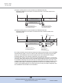
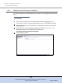
(Example 1) Setting the Eco-mode schedule via ETERNUS Web GUI
Operation schedule is set as 9:00 to 21:00 and there are no accesses outside of the
scheduled period
9:00
1:00
Stopped
0:00
21:00
Scheduled Operation
Stopped
Disk Motors Running
Disk motors are spun up
30 minutes before the start of
the scheduled operation
Disk motors are stopped
30 minutes after the end of
the scheduled operation
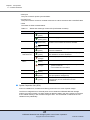
(Example 2) Setting the Eco-mode schedule via ETERNUS Web GUI
Operation schedule is set as 9:00 to 21:00 and there are accesses outside of the
scheduled period
1:00
9:00
21:00
Scheduled Operation
Disk Motors Running
Disk motors are spun up
30 minutes before the start of
the scheduled operation
Access
Access finishes
Stopped Operation
Stopped
Disk Motors Running
Access OK in
one to three minutes
Disk motors are
stopped 30 minutes
after the end of
the scheduled operation
• Eco-mode schedules are executed according to the date and time that are set in the ETERUS
DX Disk storage system. To turn on and turn off the disk motors according to the schedule
that is set, use the Network Time Protocol (NTP) server in the date and time setting in
ETERNUS Web GUI to set automatic adjustment of the date and time.
• Up to eight 2.5" drives or four 3.5" drives can be activated at the same time in a single drive
enclosure. When these maximums are exceeded, the first eight 2.5" drives or four 3.5" drives
are activated, followed by the rest of the drives in matching increments for each size. If the
number of drives that are activated in a single drive enclosure is increased, the time for drive
activation takes longer, causing the response times for the server to increase, which may
result in access paths being lost. To prevent this from occurring, the RAID configuration and
drive installation must be taken into consideration.
45
ETERNUS DX60 S2 Disk storage system User’s Guide -OperationCopyright 2012 FUJITSU LIMITED
P3AM-5512-03ENZ0
Chapter 3 Setup
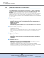
3.3 Optimizing Volume Configurations
3.3
Optimizing Volume Configurations
The ETERNUS DX Disk storage system allows for the expansion of volumes and RAID group
capacities, migration among RAID groups, and the changing of RAID levels when the volumes
are defined.
Exact details depend on the desired operation. Select from the following procedures.
This section describes the restrictions on using each function of the ETERNUS DX Disk storage
system and the notes on setting up each function of the ETERNUS DX Disk storage system.
For details on the above procedures, refer to "ETERNUS Web GUI User's Guide" or "ETERNUS
CLI User's Guide".
■ Expansion of volume capacity
• RAID Migration (with increased migration destination capacity)
When volume capacity is insufficient, a volume can be moved to a RAID group that has
enough free space. This function is recommended for use when the desired free space is
available in the destination.
• LUN Concatenation
Adds areas of free space to an existing volume to expand its capacity. This uses existing free
space to efficiently expand the volume.
■ Expansion of RAID group capacity
• Logical Device Expansion
Adds new disks to an existing RAID group to expand the RAID group capacity. This is used to
expand the existing RAID group capacity instead of adding a new RAID group to add the
volumes.
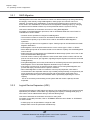
■ Migration of RAID groups
• RAID Migration
If the performance of the current RAID groups is not satisfactory due to conflicting volumes,
RAID Migration may be used to improve the performance by redistributing the RAID group
configuration.
■ Changing the RAID level
• RAID Migration (to a RAID group with a different RAID level)
Migrating to a RAID group with a different RAID level changes the RAID level of volumes.
This is used to change the RAID level for a specific volume.
• Logical Device Expansion (and changing RAID levels when adding the new disks)
The RAID level may also be changed when adding new disks to a RAID group. This is used to
convert the RAID level of all the volumes belonging to a given RAID group.
46
ETERNUS DX60 S2 Disk storage system User’s Guide -OperationCopyright 2012 FUJITSU LIMITED
P3AM-5512-03ENZ0
Chapter 3 Setup
3.3 Optimizing Volume Configurations
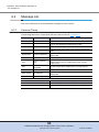
3.3.1
RAID Migration
RAID Migration is a function that transfers a volume to a different RAID group while guaranteeing
the integrity of the data. By using RAID Migration, RAID groups and volumes can be hot
switched. This allows easy redistribution of volumes among RAID groups in response to customer needs. The redistribution of volumes and reconfiguration of RAID groups (e.g. changing
the RAID level from RAID5 to RAID1+0) can be performed while the system is running.
This section describes the restrictions and notes on using RAID Migration.
For details on the RAID Migration procedure, refer to "ETERNUS Web GUI User's Guide" or
"ETERNUS CLI User's Guide".
• Volumes can be specified as a target for RAID Migration.
• The maximum number of volumes for simultaneous RAID Migration operations is 32.
• A total volume capacity of up to 8TB can be used for simultaneous RAID Migration
operations.
• The volume type that can be migrated is "Open". RAID groups can be selected as the RAID
Migration destination.
• RAID Migration cannot be performed when the source volume type is "SDV" or "SDPV".
• Select RAID groups with an unused area that is more than the capacity of the RAID Migration
source volume.
• RAID levels that are supported by the ETERNUS DX Disk storage system can be set for the
source and destination RAID groups.
• The final volume number (LUN) will be the same as the initial volume number, and from the
point of view of the server, pre-migration, migrating and post-migration volumes are accessed
indistinguishably.
• During RAID Migration, the access performance for the RAID groups that are specified as the
RAID Migration source and RAID Migration destination may be reduced.
• If the power is turned off or an electrical power outage occurs during RAID Migration, the
process will simply continue when the power is restored.
• When RAID Migration is used to increase the volume (LUN) capacities, note that the
increased size of the expanded volumes may not always be dynamically re-recognized by the
server, depending on the server-side OS (type and version) being used. Refer to the
applicable OS and file system documentation before dynamically expanding the volume
capacity.
This is not necessary when building a new system after the volume capacity has been
expanded.
3.3.2
Logical Device Expansion (LDE)
Logical Device Expansion (LDE) allows the capacity of an existing RAID group to be dynamically
expanded by the addition of extra disks. By expanding the capacity of existing RAID group, a
new volume can be added without having to add new RAID groups.
This section describes the restrictions and notes on using LDE.
For details on the LDE procedure, refer to "ETERNUS Web GUI User's Guide" or "ETERNUS
CLI User's Guide".
• A RAID group can be specified as a target for LDE.
• Multiple LDEs cannot be performed simultaneously.
47
ETERNUS DX60 S2 Disk storage system User’s Guide -OperationCopyright 2012 FUJITSU LIMITED
P3AM-5512-03ENZ0
Chapter 3 Setup
3.3 Optimizing Volume Configurations
• LDE can be performed if the new RAID group capacity is the same or larger than the old
capacity.
• When adding disks, use a disk with a capacity that is the same or with a larger capacity than
the disks in the RAID groups that are targets for LDE. After LDE completes, all the disks in the
target RAID groups are recognized as having the same capacity as the disk with the smallest
capacity in the RAID group. The rest of the capacity in the disks that have a larger capacity
cannot be used.
• LDE can be performed on a RAID group that contains an Advanced Copy target (copy source
or copy destination) volume.
• Capacity expansion and changing the level of a RAID group can be performed at the same
time.
• Since the data cannot be recovered after the failure of LDE, back up all the data of the
volumes in the target RAID group to another area before performing LDE. If LDE fails, recover
using this backup data.
• Volumes cannot be added to the target RAID groups while LDE is running. Volumes can be
added after LDE is complete. Volumes cannot be deleted from the target RAID groups while
LDE is running.
• If the power is turned off or an electrical power outage occurs during LDE, the process will
simply continue when the power is restored.
3.3.3
LUN Concatenation
LUN Concatenation is a function that is used to add new area to a volume for expanding the volume capacity available to the server. The ability to concatenate widely distributed free areas in
the ETERNUS DX Disk storage system allows efficient use of the disk capacity.
Unused areas, which may be either part or all of a RAID group, are used to create new volumes
that are then added together (concatenated) to form a single large volume.
This section describes the restrictions and notes on using LUN Concatenation.
For details on the LUN Concatenation procedure, refer to "ETERNUS Web GUI User's Guide" or
"ETERNUS CLI User's Guide".
•
•
•
•
•
Volumes can be specified as a target for LUN Concatenation.
Multiple volumes can be concatenated. Up to 16 volumes can be concatenated.
Maximum concatenated volume capacity is 32TB.
The minimum required capacity of each volume being concatenated is 1GB.
Conditions for volumes to be concatenated are as follows:
- Only "Open" type volumes can be used for LUN Concatenation. SDV cannot be
concatenated. The encryption status of a concatenated volume is the same status as a
volume that is to be concatenated.
- The RAID levels may be any that are supported by the ETERNUS DX Disk storage system
with no need for all to be the same or any other limitation. It is also possible to connect up
volumes with different RAID levels. Volumes in RAID groups with different types (such as
capacity or speed) of disks can be concatenated. However, RAID groups with the same
RAID level and same disk type are recommended for concatenated volumes to ensure
that performance is not affected.
• LUN Concatenation cannot be performed under the following conditions:
- When the volume to be concatenated contains an Advanced Copy session.
48
ETERNUS DX60 S2 Disk storage system User’s Guide -OperationCopyright 2012 FUJITSU LIMITED
P3AM-5512-03ENZ0
Chapter 3 Setup
3.3 Optimizing Volume Configurations
•
•
•
•
•
•
•
•
•
- When the number of volumes to be concatenated is fewer than the maximum number of
volumes that can be concatenated but the resulting capacity exceeds the maximum single
LUN capacity allowed by the ETERNUS DX Disk storage system.
It is possible to add extra volumes to an already concatenated volume.
After concatenation, any number of formatting processes can be started at once.
Because the server-side LUNs are not changed by volume concatenation, an OS reboot is
not required. However, this function only expands the volumes in the ETERNUS DX Disk
storage system. Server-side recognition and volume expansion is OS dependent.
The logical unit number of each concatenated volume does not change and remains
accessible from the server before, during, and after the concatenation.
If the power is turned off or an electrical power outage occurs during LUN Concatenation, the
concatenation will simply continue the next time the power is turned on.
It is recommended that the data on the volumes that are to be concatenated be backed up
first.
When LUN Concatenation is used to increase the volume (LUN) capacities, note that the
increased size of the expanded volumes may not always be dynamically re-recognized by the
server, depending on the server-side OS (type and version) being used. Refer to the
applicable OS and file system documentation before dynamically expanding the volume
capacity.
This is not necessary when building a new system after the volume capacity has been
expanded.
A concatenated volume can be used as an OPC, EC, or QuickOPC copy source or copy
destination. It can also be used as a SnapOPC+ copy source.
When a volume that is using ETERNUS SF AdvancedCopy Manager to run backups is
expanded via LUN Concatenation, the volume will need to be registered with ETERNUS SF
AdvancedCopy Manager again.
49
ETERNUS DX60 S2 Disk storage system User’s Guide -OperationCopyright 2012 FUJITSU LIMITED
P3AM-5512-03ENZ0
Chapter 4
Operations
This chapter describes the control of the LAN for operation management of the ETERNUS DX
Disk storage system, and the monitoring the status of the ETERNUS DX Disk storage system.
LAN for Operation Management
The ETERNUS DX Disk storage system must be connected to the LAN for operation management. When remote support is used, information on errors of the ETERNUS DX Disk storage
system or other events can be notified to the remote support center.
This section explains how the LAN control controller of the ETERNUS DX Disk storage system
operates.
■ LAN Control Controller (Master CM/Slave CM)
CM#0
has failed
IP:x.x.x.a
Slave
CM
MNT
Master
CM
RMT
MNT
RMT
For a dual-controller type, the controller (CM) that is given the authority to manage the LAN is
called the Master CM and the other CM is called the Slave CM.
When an error occurs in the Master CM or LAN, the Master CM is switched automatically.
IP addresses of the LAN ports are not assigned to each CM. These IP addresses are assigned to
the role of master or slave. If the Master CM is switched, the same IP addresses are reused.
Therefore, even if the Master CM is switched and the physical port is changed, access can be
maintained via the same IP addresses.
CM#0
CM#1
Controller enclosure
ETERNUS DX Disk storage system
CM#0
IP:x.x.x.a
Controller enclosure
CM#1
When the Master CM is
switched, the IP addresses
of the previous Master CM’s
are taken over by the new
Master CM.
ETERNUS DX Disk storage system
Figure 4.1
Master
CM
MNT
Slave
CM
RMT
MNT
The Master CM is switched.
RMT
4.1
LAN control (switching of the Master CM)
50
ETERNUS DX60 S2 Disk storage system User’s Guide -OperationCopyright 2012 FUJITSU LIMITED
P3AM-5512-03ENZ0
Chapter 4 Operations
4.2 Monitoring ETERNUS DX Disk Storage System Status
• Each CM has an LED that lights up green to identify when it is the
Master CM.
• Setting the IP address of the Slave CM ensures that ETERNUS Web
GUI or ETERNUS CLI can be used from the Slave CM if an error occurs
on the LAN path for the Master CM.
The Master CM and the Slave CM perform different functions. The
Slave CM can only switch the Master CM and display the status of the
ETERNUS DX Disk storage system.
The IP address of the Slave CM does not need to be set for normal
operation.
IP:x.x.x.a
CM#0
Controller enclosure
ETERNUS DX Disk storage system
Figure 4.2
4.2
Slave
CM
MNT
Master
CM
RMT
MNT
RMT
LAN path
error
IP:x.x.x.b
CM#1
The IP address of the Slave CM is used
to switch the Master CM and display
the status of
the ETERNUS DX Disk storage system.
LAN control (when the IP address of the Slave CM is set)
Monitoring ETERNUS DX Disk Storage System
Status
Check the status of the ETERNUS DX Disk storage system regularly by checking the LEDs or
the status display function of ETERNUS Web GUI.
CAUTION
Impending trouble may be indicated by the warning message FAULT
LEDs of the ETERNUS DX Disk storage system. The LEDs and the
general status of ETERNUS Web GUI should be checked regularly to
prevent any serious trouble from occurring.
In addition, setting event notification enables e-mail notification messages or SNMP Trap
messages for events with the ETERNUS DX Disk storage system in order to monitor the status
of the ETERNUS DX Disk storage system.
Event notification and status display for the ETERNUS DX Disk storage
system can be performed by ETERNUS CLI. When ETERNUS CLI is used,
refer to "ETERNUS CLI User's Guide".
51
ETERNUS DX60 S2 Disk storage system User’s Guide -OperationCopyright 2012 FUJITSU LIMITED
P3AM-5512-03ENZ0
Chapter 4 Operations
4.2 Monitoring ETERNUS DX Disk Storage System Status
4.2.1
LED Status Check
The status of the ETERNUS DX Disk storage system can be checked by the LEDs.
If the FAULT LED in front of the ETERNUS DX Disk storage system is orange, contact your
maintenance engineer.
4.2.2
Displaying Status via ETERNUS Web GUI
The status of the ETERNUS DX Disk storage system can be checked in the Overview screen of
ETERNUS Web GUI.
Figure 4.3
ETERNUS Web GUI screen
Table 4.1 shows the general status.
Status of each component in the ETERNUS DX Disk storage system is monitored periodically,
and the result is displayed as a general status image with character strings.
52
ETERNUS DX60 S2 Disk storage system User’s Guide -OperationCopyright 2012 FUJITSU LIMITED
P3AM-5512-03ENZ0
Chapter 4 Operations
4.2 Monitoring ETERNUS DX Disk Storage System Status
Table 4.1
General status of ETERNUS Web GUI
General status
ETERNUS DX Disk storage system status
The ETERNUS DX Disk storage system is in normal state.
Normal (Green)
Not Ready (Red)
The ETERNUS DX Disk storage system is in error state.
Error (Red)
Maintenance (Orange)
Warning (Yellow)
Warning (Gray)
"Not Ready" is a status where an abnormality is detected at a
power-off, and I/O access from the server cannot be received.
The ETERNUS DX Disk storage system is under maintenance.
The ETERNUS DX Disk storage system is in warning state.
The component is installed in the ETERNUS DX Disk storage
system, but not used.
Refer to "ETERNUS Web GUI User's Guide" for details.
4.2.3
Event Notification
By setting event notification, if an error (event) occurs in the ETERNUS DX Disk storage system,
the event information is notified.
The methods that can be used to notify an event are "E-Mail", "SNMP Trap", "REMCS", and
"Host Sense Key Code Qualifier". Note that REMCS is not available in the EMEA&I region.
For the procedure on setting event notification, refer to "User's Guide -Installation-".
■ E-Mail
When an event occurs in the ETERNUS DX Disk storage system, an e-mail is sent to the specified e-mail address.
For more details on notified event information, refer to "Appendix A Event Notification Message
List" (page 87).
■ SNMP Trap
When an event occurs in the ETERNUS DX Disk storage system, an SNMP Trap is sent to the
SNMP Manager (monitoring server).
For more details on event information notified by SNMP Trap, refer to "Appendix A Event
Notification Message List" (page 87).
■ REMCS
The information for errors that occur in the ETERNUS DX Disk storage system is notified to the
remote support center.
Warning and Error events are notified.
■ Host Sense Key Code Qualifier
When an event occurs in the ETERNUS DX Disk storage system, host senses (sense codes) are
sent to the server. For details on sense codes, refer to "Appendix A Event Notification Message
List" (page 87).
53
ETERNUS DX60 S2 Disk storage system User’s Guide -OperationCopyright 2012 FUJITSU LIMITED
P3AM-5512-03ENZ0
Chapter 4 Operations
4.2 Monitoring ETERNUS DX Disk Storage System Status
Mail
server
Server (host)
SNMP
manager
SNMP Trap
E-mail
Remote
support
center
Host sense
ETERNUS DX Disk
storage system
REMCS/SNMP (*1)
*1: SNMP for the EMEA&I region and REMCS for all other regions
Figure 4.4
Event notification
54
ETERNUS DX60 S2 Disk storage system User’s Guide -OperationCopyright 2012 FUJITSU LIMITED
P3AM-5512-03ENZ0
Chapter 5
Installing Optional Products
The following optional products can be installed in the ETERNUS DX Disk storage system:
•
•
•
•
Disk
Drive enclosure
Controller
Expander
This chapter explains the installation rules, handling instructions, and installation procedures for
these optional products.
Disks and drive enclosures can be added by yourself.
However, be sure to read "Safety Precautions" before performing any of these installation
procedures.
5.1
Installing Disks
Optional disks can be installed while the ETERNUS DX Disk storage system is running without
affecting the system.
This section explains how to install optional disks.
CAUTION
Do Not
• Do not uninstall or move a disk that is already installed.
Contact your sales representative or maintenance engineer if disks
that are installed by default need to be uninstalled or moved to
another slot.
55
ETERNUS DX60 S2 Disk storage system User’s Guide -OperationCopyright 2012 FUJITSU LIMITED
P3AM-5512-03ENZ0
Chapter 5 Installing Optional Products
5.1 Installing Disks
Firmware version V20L11 or later is required in the ETERNUS DX Disk
storage system to add disks.
The firmware version that is currently in use can be checked via ETERNUS
Web GUI or ETERNUS CLI. If an older firmware version is being used,
request a firmware upgrade from your sales representative.
IMPORTANT
Installation Rules for Disks
This section explains the installation rules for disks.
■ 2.5" disks
2.5" disks can be installed in the front side of a 2.5" type controller enclosure.
Figure 5.1
Slot#23
Slot#22
Slot#21
Slot#20
Slot#19
Slot#18
Slot#17
Slot#16
Slot#15
Slot#14
Slot#13
Slot#11
Slot#12
Slot#10
Slot#9
Slot#8
Slot#7
Slot#6
Slot#5
Slot#4
Slot#3
Slot#2
Slot#1
Disks can be installed in any slots of an enclosure.
Figure 5.1 shows the positions of 2.5" disk slots.
Slot#0
5.1.1
Position of 2.5" disk slots
Do Not
WARNING
• System disks are installed in Slot#0 and Slot#1. Never remove system
disks. Doing so will render the ETERNUS DX Disk storage system
unusable.
■ 3.5" disks
3.5" disks can be installed in the front side of a 3.5" type controller enclosure or a 3.5" type drive
enclosure.
Different types of disks can be installed in the same enclosure. Disks can be installed in any slots
of an enclosure.
Figure 5.2 shows the positions of 3.5" disk slots.
56
ETERNUS DX60 S2 Disk storage system User’s Guide -OperationCopyright 2012 FUJITSU LIMITED
P3AM-5512-03ENZ0
Chapter 5 Installing Optional Products
5.1 Installing Disks
Figure 5.2
Slot#8
Slot#9
Slot#10
Slot#11
Slot#4
Slot#5
Slot#6
Slot#7
Slot#0
Slot#1
Slot#2
Slot#3
Position of 3.5" disk slots
Do Not
WARNING
• System disks are installed in Slot#0 and Slot#1 of the controller
enclosure. Never remove system disks. Doing so will render the
ETERNUS DX Disk storage system unusable.
5.1.2
Installable Disks
Table 5.1 and Table 5.2 show the installable disks.
Table 5.1
Installable disks (2.5" disks)
Model name
Product name
ETED3HB-L, FTS:ETED3HB-L
Disk Drive(2.5inch) 300GB 10krpm x1 for DX60 S2
ETED4HB-L, FTS:ETED4HB-L
Disk Drive(2.5inch) 450GB 10krpm x1 for DX60 S2
ETED6HB-L, FTS:ETED6HB-L
Disk Drive(2.5inch) 600GB 10krpm x1 for DX60 S2
ETED9HB-L, FTS:ETED9HB-L
Disk Drive(2.5inch) 900GB 10krpm x1 for DX60 S2
ETEN1HB-L, FTS:ETEN1HB-L
Disk Drive(2.5inch) 1TB 7.2krpm x1 for DX60 S2
Table 5.2
Installable disks (3.5" disks)
Model name
Product name
ETED3HA-L, FTS:ETED3HA-L
Disk Drive(3.5inch) 300GB 15krpm x1 for DX60 S2
ETED4HA-L, FTS:ETED4HA-L
Disk Drive(3.5inch) 450GB 15krpm x1 for DX60 S2
ETED6HA-L, FTS:ETED6HA-L
Disk Drive(3.5inch) 600GB 15krpm x1 for DX60 S2
ETEN1HA-L, FTS:ETEN1HA-L
Disk Drive(3.5inch) 1TB 7.2krpm x1 for DX60 S2
ETEN2HA-L, FTS:ETEN2HA-L
Disk Drive(3.5inch) 2TB 7.2krpm x1 for DX60 S2
ETEN3HA-L, FTS:ETEN3HA-L
Disk Drive(3.5inch) 3TB 7.2krpm x1 for DX60 S2
At time of purchase, the installable disk type may be different from those described.
To find the web-site to check the latest version of this manual, refer to "Read Me First".
57
ETERNUS DX60 S2 Disk storage system User’s Guide -OperationCopyright 2012 FUJITSU LIMITED
P3AM-5512-03ENZ0
Chapter 5 Installing Optional Products
5.1 Installing Disks
5.1.3
Disk Handling Instructions
■ About condensation
Do
CAUTION
• When moving a disk from a cold place, such as an un-conditioned
store house in winter, to a warmer places such as an air-conditioned
room, the severe temperature change may result in condensation
forming.
To avoid this, allow the packed disks sufficient time in the warmer
place (one hour for each 15°C of temperature difference) to adapt to
the new temperature.
■ About static electricity
CAUTION
Do Not
• Do not touch the surface of the board of the disks.
Do
• When handling disks, make sure to wear a wrist strap or touch a metal
part to discharge the human body's natural static electricity. Failure to
discharge static electricity may cause device failure.
• Leave the disk in its package until ready to install it.
58
ETERNUS DX60 S2 Disk storage system User’s Guide -OperationCopyright 2012 FUJITSU LIMITED
P3AM-5512-03ENZ0
Chapter 5 Installing Optional Products
5.1 Installing Disks
■ About shock
CAUTION
Do Not
• Do not lay the disks directly on a desk or similar hard surface. Always
use a rubber mat or other soft material to cushion the disks against
physical shocks.
• Do not stack disks or stand disks on end.
• Do not apply external force to the interface connectors.
• Do not knock or drop the disks on hard objects.
59
ETERNUS DX60 S2 Disk storage system User’s Guide -OperationCopyright 2012 FUJITSU LIMITED
P3AM-5512-03ENZ0
Chapter 5 Installing Optional Products
5.1 Installing Disks
5.1.4
Additional Disk Installation Procedure
This section describes how to install additional disks in the ETERNUS DX Disk storage system.
Do
CAUTION
• If additional disks are installed in a way other as described in this
section, damage and/or device failure or electrical shock may occur.
Do Not
• Do not install disks that are for use in other devices.
■ 2.5" disks
Procedure
1
Check that all components of the ETERNUS DX Disk storage system are in
normal status, using the Storage System Status screen of ETERNUS Web GUI.
2
Wear a wrist strap or touch a metal part to discharge the human body's natural
static electricity.
3
Remove the dummy disk unit from the slot in which the disk is to be installed.
Simultaneously push into the tabs in the upper and lower parts of the dummy disk unit, and
pull it straight out of the disk slot.
Dummy disk unit
Tabs
IMPORTANT
The removed dummy disk unit should be retained for future use.
60
ETERNUS DX60 S2 Disk storage system User’s Guide -OperationCopyright 2012 FUJITSU LIMITED
P3AM-5512-03ENZ0
Chapter 5 Installing Optional Products
5.1 Installing Disks
4
Install the new disk.
4-1 Press the catch on the disk lock lever to unlock it.
Catch
Lock lever
4-2 Insert the disk all the way into in the slot, making sure that it is firmly seated and
keeping the lock lever open.
IMPORTANT
Hold the disk with both hands to protect against jarring.
4-3 Swing the lock lever in the direction of the arrow, until the lock clicks shut.
Lock lever
4-4 Check that the newly installed disk's DISK READY LED lights up green after
approximately 30 seconds.
5
Repeat Step 3 and Step 4 for each additional disk.
6
If a wrist strap is used, remove the wrist strap.
7
On the Storage System Status screen of ETERNUS Web GUI, check that the
added disks have been recognized.
61
ETERNUS DX60 S2 Disk storage system User’s Guide -OperationCopyright 2012 FUJITSU LIMITED
P3AM-5512-03ENZ0
Chapter 5 Installing Optional Products
5.1 Installing Disks
8
Set up RAID groups, volumes, hot spares, and Host Affinity settings on the new
disks, as required.
End of procedure
■ 3.5" disks
Procedure
1
Check that all components of the ETERNUS DX Disk storage system are in
normal status, using the Storage System Status screen of ETERNUS Web GUI.
2
Remove the front cover.
For details on how to attach the front cover, refer to "2.3 Attaching and Removing the Front
Cover" (page 37).
3
Wear a wrist strap or touch a metal part to discharge the human body's natural
static electricity.
4
Remove the dummy disk unit from the slot in which the disk is to be installed.
Hook your fingers and push into the holes of the dummy disk unit, and pull it straight out of
the disk slot.
Dummy disk unit
IMPORTANT
The removed dummy disk unit should be retained for future use.
62
ETERNUS DX60 S2 Disk storage system User’s Guide -OperationCopyright 2012 FUJITSU LIMITED
P3AM-5512-03ENZ0
Chapter 5 Installing Optional Products
5.1 Installing Disks
5
Install the new disk.
5-1 Press the catch on the disk lock lever to unlock it.
Catch
1
2
Lock lever
5-2 Insert the disk all the way into in the slot, making sure that it is firmly seated and
keeping the lock lever open.
IMPORTANT
• Hold the disk with both hands to protect against jarring.
• Insert the disk until the lock lever hooks reach the slot
protrusions.
5-3 Swing the lock lever in the direction of the arrow, until the lock clicks shut.
Lock lever
IMPORTANT
Make sure that the lock lever hooks have engaged the slot
protrusions.
Lock lever hooks
have engaged
Lock lever hooks
have not engaged
Slot
protrusion
Slot
protrusion
Hook
Hook
5-4 Check that the newly installed disk’s DISK READY/FAULT LED lights up green after
approximately 30 seconds.
63
ETERNUS DX60 S2 Disk storage system User’s Guide -OperationCopyright 2012 FUJITSU LIMITED
P3AM-5512-03ENZ0
Chapter 5 Installing Optional Products
5.2 Installing Drive Enclosures
6
Repeat Step 4 and Step 5 for each additional disk.
7
Remove the wrist strap.
8
Remove the front cover.
For details on how to attach the front cover, refer to "2.3 Attaching and Removing the
Front Cover" (page 37).
9
On the Storage System Status screen of ETERNUS Web GUI, check that the
added disks have been recognized.
10 Set up RAID groups, volumes, hot spares, and Host Affinity settings on the new
disks, as required.
End of procedure
5.2
Installing Drive Enclosures
Optional drive enclosures can be installed while the ETERNUS DX Disk storage system is running without affecting the system.
This section explains how to install optional drive enclosures.
5.2.1
Installation Rules for Drive Enclosures
Only one drive enclosure can be connected to a 3.5" type controller enclosure.
Drive enclosures cannot be connected to 2.5" type controller enclosures.
5.2.2
Installable Drive Enclosures
Table 5.3 shows the installable drive enclosures.
Table 5.3
Installable drive enclosures
Model name
Product name
ETEED1DU-L, FTS:ETEED1DU-L
Drive enclosure for DX60 S2 (3.5inch, single-expander type)
ETEED2DU-L, FTS:ETEED2DU-L
Drive enclosure for DX60 S2 (3.5inch, dual-expander type)
At time of purchase, the installable drive enclosure model may be different from those described.
To find the web-site to check the latest version of this manual, refer to "Read Me First".
64
ETERNUS DX60 S2 Disk storage system User’s Guide -OperationCopyright 2012 FUJITSU LIMITED
P3AM-5512-03ENZ0
Chapter 5 Installing Optional Products
5.2 Installing Drive Enclosures
5.2.3
Drive Enclosure Handling Instructions
■ About condensation
Do
CAUTION
• When moving a drive enclosure from a cold place, such as an unconditioned store house in winter, to a warmer place such as an airconditioned room, the severe temperature change may result in
condensation forming.
To avoid this, allow the packed drive enclosures sufficient time in the
warmer place (one hour for each 15°C of temperature difference) to
adapt to the new temperature.
■ About static electricity
Do
CAUTION
• When handling drive enclosures, make sure to wear a wrist strap or
touch a metal part to discharge the human body's natural static
electricity. Failure to discharge static electricity may cause device
failure.
■ About shock
CAUTION
Do Not
• Do not handle the drive enclosure roughly or subject it to physical
shocks when laying it down.
• Do not stack the drive enclosures.
• Do not knock or drop the drive enclosure on hard objects.
65
ETERNUS DX60 S2 Disk storage system User’s Guide -OperationCopyright 2012 FUJITSU LIMITED
P3AM-5512-03ENZ0
Chapter 5 Installing Optional Products
5.2 Installing Drive Enclosures
5.2.4
Drive Enclosure Rack Installation Procedure
This section describes how to install a drive enclosure in a rack.
Do
CAUTION
• If drive enclosures are installed in a way other as described herein,
damage and/or device failure or electrical shock may occur.
• Do not install drive enclosures with cables, such as power cords,
connected.
• Do not knock the other devices installed in the rack when installing
drive enclosures.
IMPORTANT
• Connect the cables after installing the drive enclosure in a rack by
following the "Add Drive Enclosure" procedure of ETERNUS Web GUI.
• Install the disk after expanding the drive enclosure.
Procedure
1
Wear a wrist strap or touch a metal part to discharge the human body's natural
static electricity.
2
Attach the rack rails to the rack.
■ For the EMEA&I region
(1)Attach the 2U rack rail to the left rear rack pillar.
The M5 centering screws should be inserted in the 1st and 6th holes above the base
line of the controller enclosure.
2U Bracket
M5 Centering screws (10mm)
66
ETERNUS DX60 S2 Disk storage system User’s Guide -OperationCopyright 2012 FUJITSU LIMITED
P3AM-5512-03ENZ0
Chapter 5 Installing Optional Products
5.2 Installing Drive Enclosures
(2)Insert the pins of the left slide rail in the 1st and 3rd holes from the bottom of the 2U
rack rail.
(3)Secure the left slide rail to the front pillar using the M5 centering screw and M5 pan
head screws.
(4)For the right slide rail, insert the pins in the holes of the rear pillar, and secure the other
side of the slide rail to the front pillar in the same way as the left slide rail.
M5 Centering screw (10mm)
M5 Cage nut
M5 Pan head screw (10mm)
(5)Push the M5 cage nuts into the 2nd holes of the front rack pillars above the base line of
the drive enclosure.
The M5 centering screw and M5 pan head screw positions for the slide rails and 2U
rack rail are determined relatively to the base line of the drive enclosure.
Tighten the screws referring to the following figure.
[Left]
[Right]
3rd position
(M5 centering screw)
3rd position
(M5 centering screw)
2nd position
(M5 cage nut)
2U
Drive enclosure
2nd position
(M5 cage nut)
1st position
(M5 pan head screw)
1st position
(M5 pan head screw)
Base line of
drive enclosure
Rack rails
67
ETERNUS DX60 S2 Disk storage system User’s Guide -OperationCopyright 2012 FUJITSU LIMITED
P3AM-5512-03ENZ0
Chapter 5 Installing Optional Products
5.2 Installing Drive Enclosures
■ For regions other than EMEA&I
(1)Adjust the sizes of the rack rail (for left side) and the rack rail (for right side) to fit the
rack.
Loosen the M4 screws to adjust the length of the rack rails to match the distance
between the front and rear rack pillars. Leave the M4 screws slightly unscrewed, as the
rack rail must be attached to the rack before they can be completely tightened.
(Rear rack pillars)
Loosen the M4 screws, and
adjust the rack rails to the depth
of the rack.
Rack rail (for left side)
"L" is stamped on the inner
side of the rack rail
(for left side).
[Left]
(Front rack pillars)
Rack rail (for right side)
"R" is stamped on the inner
side of the rack rail
(for right side).
[Right]
(2)Attach the rack rails to the rack.
• If the rack pillars have square (approx. 9mm) holes, screw
holders will need to be used when attaching the rack rails.
• Make sure to attach the rack rails and rack pillars so that they
fit exactly together without any space between them.
Washers
M5 screws
M5 screws
Rack rail (for left side)
(Rear rack pillars)
Washers
Washers
M5 screws
(Front rack pillars)
M5 screws
Rack rail (for right side)
Washers
68
ETERNUS DX60 S2 Disk storage system User’s Guide -OperationCopyright 2012 FUJITSU LIMITED
P3AM-5512-03ENZ0
Chapter 5 Installing Optional Products
5.2 Installing Drive Enclosures
The M5 screw positions for the rack rails are determined relative to the drive enclosure
base line.
The M5 screws should be inserted in the 1st and 3rd holes above the base line.
[Left]
3rd position
(M5 screws)
[Right]
2U
3rd position
(M5 screws)
Drive enclosure
1st position
(M5 screws)
1st position
(M5 screws)
Base line of
drive enclosure
Rack rails
(3)Tighten the M4 screws of the rack rails that were slightly unscrewed in Step (1).
3
Remove the front cover.
For details on how to attach the front cover, refer to "2.3 Attaching and Removing the Front
Cover" (page 37).
4
Install the drive enclosure in the rack.
Do
CAUTION
• When installing or removing the drive enclosure to or from the
rack, make sure to have the right and left sides and the bottom
of the drive enclosure by two or more people. Failure to do so
may cause injury.
5
Fix the drive enclosure in the rack.
Use the two thumb screws at the front of the drive enclosure to fasten it in the rack.
(Rear rack pillars)
Thumb screw
69
ETERNUS DX60 S2 Disk storage system User’s Guide -OperationCopyright 2012 FUJITSU LIMITED
P3AM-5512-03ENZ0
Chapter 5 Installing Optional Products
5.2 Installing Drive Enclosures
6
Check the settings of the AUTO POWER switch and the MODE SELECT switch.
• AUTO POWER switch
Check that the AUTO POWER switch is set to the OFF position. Do not change to ON.
• MODE SELECT switch
Check that the MODE SELECT switch is set to the ON position. Do not change to OFF.
AUTO POWER
switch
MODE SELECT
switch
End of procedure
70
ETERNUS DX60 S2 Disk storage system User’s Guide -OperationCopyright 2012 FUJITSU LIMITED
P3AM-5512-03ENZ0
Chapter 5 Installing Optional Products
5.2 Installing Drive Enclosures
5.2.5
Additional Drive Enclosure Installation
This section explains how to install additional drive enclosures in the ETERNUS DX Disk storage
system.
Procedure
1
Check that all components of the ETERNUS DX Disk storage system are in
normal status, using the Storage System Status screen of ETERNUS Web GUI.
2
Wear a wrist strap or touch a metal part to discharge the human body's natural
static electricity.
3
Click [Add Drive Enclosure] under the [Hardware Maintenance] menu on the
[Maintenance] tab in the ETERNUS Web GUI screen.
The [Add Drive Enclosure] initial screen appears.
4
Click the [Next>] button.
71
ETERNUS DX60 S2 Disk storage system User’s Guide -OperationCopyright 2012 FUJITSU LIMITED
P3AM-5512-03ENZ0
Chapter 5 Installing Optional Products
5.2 Installing Drive Enclosures
A screen to show how to install the drive enclosure appears.
5
Connect the miniSAS cable (for drive enclosures).
5-1 Connect the DI (OUT) port at controller 0 (CM#0) of controller enclosure, to the DI (IN)
port at expander 0 (EXP#0) of the drive enclosure 1 with the miniSAS cable.
(1) Connect the plug to be connected to DI (OUT) port, to the DI (OUT) port of the
Controller 0 (CM#0).
Remove the port cover from the DI (OUT) port before inserting the plug.
Controller enclosure
72
ETERNUS DX60 S2 Disk storage system User’s Guide -OperationCopyright 2012 FUJITSU LIMITED
P3AM-5512-03ENZ0
Chapter 5 Installing Optional Products
5.2 Installing Drive Enclosures
(2) Connect the plug to be connected to DI (IN) port, to the DI (IN) port of the expander
0 (EXP#0).
Drive enclosure
5-2 For a dual-controller type, connect the DI (OUT) port at controller 1 (CM#1) of controller
enclosure, to the DI (IN) port at expander 1 (EXP#1) of the drive enclosure 1 with the
miniSAS cable.
Connect the miniSAS cable in the same way as Step 5-1.
The following shows the miniSAS connection figure between controller enclosure and
drive enclosure.
IMPORTANT
Do not connect anything to the DI (OUT) port on the drive enclosure.
- For a single-controller type
EXP#0
Drive enclosure
Controller enclosure
CM#0
73
ETERNUS DX60 S2 Disk storage system User’s Guide -OperationCopyright 2012 FUJITSU LIMITED
P3AM-5512-03ENZ0
Chapter 5 Installing Optional Products
5.2 Installing Drive Enclosures
- For a dual-controller type
EXP#0
EXP#1
Drive enclosure
Controller enclosure
6
CM#0
CM#1
Connect the power cord to the drive enclosure.
IMPORTANT
A drive enclosure has two power supply units (PSU#0 and PSU#1).
The power cords must be connected to the inlets of both power
supply units.
6-1 Connect the power cord plugs to the inlets of the power supply units.
PSU#0
PSU#1
Inlets
Power cord plug
74
ETERNUS DX60 S2 Disk storage system User’s Guide -OperationCopyright 2012 FUJITSU LIMITED
P3AM-5512-03ENZ0
Chapter 5 Installing Optional Products
5.2 Installing Drive Enclosures
6-2 Fix the plug of the power cord with the release tie.
Wrap the release tie around the power cord. The release tie can be fastened from
either side.
Release tie
7
Connect the power cords to the socket.
Connect the plug at the other end of each power cord to the socket.
IMPORTANT
CAUTION
Power supply failure can be prevented by connecting the power
cords on the PSU#0 side and the PSU#1 side to different power
sources.
Do Not
• Do not use the server service outlet to connect a power cord for
the ETERNUS DX Disk storage system.
The drive enclosure turns on.
8
Check that the drive enclosure's POWER LED and READY LED are on.
Drive enclosure
9
Click the [Next>] button.
The drive enclosure recognition process is performed. When the process completes, the
drive enclosure's AUTO POWER switch check procedure screen is displayed.
75
ETERNUS DX60 S2 Disk storage system User’s Guide -OperationCopyright 2012 FUJITSU LIMITED
P3AM-5512-03ENZ0
Chapter 5 Installing Optional Products
5.2 Installing Drive Enclosures
10 Check the drive enclosure's AUTO POWER switch is OFF, and click the [Next>]
button.
The expansion completion screen is displayed.
11 Click the [OK] button.
The [Add Drive Enclosure] screen is closed.
12 On the Storage System Status screen, check that the added drive enclosures
have been recognized.
13 Install the disks.
Refer to "5.1.4 Additional Disk Installation Procedure" (page 60) for the appropriate
procedure.
14 If a wrist strap is used, remove the wrist strap.
15 Attach the front cover.
For details on how to attach the front cover, refer to "2.3 Attaching and Removing the Front
Cover" (page 37).
End of procedure
76
ETERNUS DX60 S2 Disk storage system User’s Guide -OperationCopyright 2012 FUJITSU LIMITED
P3AM-5512-03ENZ0
Chapter 6
Maintenance
This chapter describes maintenance for the ETERNUS DX Disk storage system.
6.1
Periodic Backup
In case of a system failure, important data should be regularly backed up.
Do
CAUTION
• We recommend that you backup important data regularly. If the
ETERNUS DX Disk storage system fails and the data has not been
backed up, it may be lost.
6.2
Volume Formatting Time
Table 6.1 shows the time for volume formatting (when the volume capacity is 100GB).
Table 6.1
Time for volume formatting (disk)
RAID level
No. of disks
Volume formatting time (*1)
2.5" SAS disks
3.5" SAS disks
Nearline SAS disks
RAID1
2
Approx. 40 minutes/
100GB
Approx. 35 minutes/
100GB
Approx. 73 minutes/
100GB
RAID1+0
8
Approx. 30 minutes/
100GB
Approx. 25 minutes/
100GB
Approx. 43 minutes/
100GB
RAID5
5
Approx. 25 minutes/
100GB
Approx. 25 minutes/
100GB
Approx. 49 minutes/
100GB
RAID5+0
6
Approx. 30 minutes/
100GB
Approx. 25 minutes/
100GB
Approx. 43 minutes/
100GB
RAID6
6
Approx. 40 minutes/
100GB
Approx. 30 minutes/
100GB
Approx. 58 minutes/
100GB
*1:
The value shows the time required for volume formatting when the volume capacity is 100GB and
there is no server I/O. The time that is required depends on the type and configuration of the disk.
77
ETERNUS DX60 S2 Disk storage system User’s Guide -OperationCopyright 2012 FUJITSU LIMITED
P3AM-5512-03ENZ0
Chapter 6 Maintenance
6.3 Rebuild/Copyback Process Time
6.3
Rebuild/Copyback Process Time
This section explains the time required for Rebuild/Copyback.
■ Rebuild process time
Table 6.2 shows the time required for the rebuild process (when the volume capacity is 100GB).
Table 6.2
Rebuild process time (disk)
RAID level
No. of disks
Rebuild process time (*1)
2.5" SAS disks
3.5" SAS disks
Nearline SAS disks
RAID1
2
Approx. 27 minutes/
100GB
Approx. 20 minutes/
100GB
Approx. 47 minutes/
100GB
RAID1+0
8
Approx. 7 minutes/
100GB
Approx. 5 minutes/
100GB
Approx. 11 minutes/
100GB
RAID5
5
Approx. 10 minutes/
100GB
Approx. 10 minutes/
100GB
Approx. 15 minutes/
100GB
RAID5+0
6
Approx. 7 minutes/
100GB
Approx. 7 minutes/
100GB
Approx. 11 minutes/
100GB
RAID6
6
Approx. 13 minutes/
100GB
Approx. 13 minutes/
100GB
Approx. 21 minutes/
100GB
*1:
The time required to rebuild a 100GB volume of the indicated RAID level, number and type of disks
when there is no concurrent server I/O. The time that is required depends on the type and
configuration of the disk.
■ Copyback process time
Table 6.3 shows the time required for the copyback process (when the volume capacity is
100GB).
Table 6.3
Copyback process time (disk)
RAID level
No. of disks
Copyback process time (*1)
2.5" SAS disks
3.5" SAS disks
Nearline SAS disks
RAID1
2
Approx. 27 minutes/
100GB
Approx. 20 minutes/
100GB
Approx. 49 minutes/
100GB
RAID1+0
8
Approx. 7 minutes/
100GB
Approx. 5 minutes/
100GB
Approx. 11 minutes/
100GB
RAID5
5
Approx. 10 minutes/
100GB
Approx. 7 minutes/
100GB
Approx. 16 minutes/
100GB
RAID5+0
6
Approx. 7 minutes/
100GB
Approx. 5 minutes/
100GB
Approx. 11 minutes/
100GB
RAID6
6
Approx. 13 minutes/
100GB
Approx. 13 minutes/
100GB
Approx. 20 minutes/
100GB
*1:
The time required to copyback a 100GB volume of the indicated RAID level, number and type of disks
when there is no concurrent server I/O. The time that is required depends on the type and
configuration of the disk.
78
ETERNUS DX60 S2 Disk storage system User’s Guide -OperationCopyright 2012 FUJITSU LIMITED
P3AM-5512-03ENZ0
Chapter 6 Maintenance
6.4 Maintenance Service
6.4
Maintenance Service
This section explains the ETERNUS DX Disk storage system maintenance service.
IMPORTANT
6.4.1
When performing maintenance service, the maintenance engineer
connects a PC terminal used for maintenance to the ETERNUS DX Disk
storage system. Also, the maintenance engineer may require information
that is necessary for performing maintenance operations.
If the maintenance engineer has any requirement, we ask that they be
handled.
Maintenance Support Period
The standard maintenance support period for ETERNUS DX Disk storage system is five years
from the date of purchase, or is defined in your service level agreement (SLA).
6.4.2
Related Service
■ Remote Support
If a possible error that may occur is detected or an error occurs when remote support is used, the
contents of events are automatically sent to the remote support center and then the user is
notified by the remote support center.
79
ETERNUS DX60 S2 Disk storage system User’s Guide -OperationCopyright 2012 FUJITSU LIMITED
P3AM-5512-03ENZ0
Chapter 7
Troubleshooting
This chapter explains troubleshooting when errors occur.
If you notice anything unusual during operation, then refer to "7.1 Check List" (page 80) to check
the ETERNUS DX Disk storage system status, prepare the necessary information with "7.2
Required Information for Inquiries" (page 85), and contact your maintenance engineer.
•
•
•
•
•
•
•
•
7.1
When the ETERNUS DX Disk storage system is turned off
When the ETERNUS DX Disk storage system refuses to turn on
When the READY LED is not on
When the FAULT LED is on
When the FAULT LED blinks
When the ETERNUS DX Disk storage system cannot be connected via a network service
When I/O access is slow
When the server does not recognize the volumes
Check List
■ When the ETERNUS DX Disk storage system is turned off
Check the following points: If none of these resolve the problem, leave the ETERNUS DX Disk
storage system alone and contact your maintenance engineer.
• Is the ETERNUS DX Disk storage system's power cord disconnected?
• Is main line switch of power distribution unit (MAIN LINE SWITCH) turned to OFF (O)?
• Has the server been turned off?
If the ETERNUS DX Disk storage system power is in conjunction with the power synchronized
unit, the power of the ETERNUS DX Disk storage system will turn off when the server is
turned off.
• Is there a power failure?
• Has there been a recent main power failure?
If the ETERNUS DX Disk storage system is in AC automatic power mode (i.e. AUTO POWER
switch is turned to ON), the ETERNUS DX Disk storage system turns on automatically after
the power is restored.
80
ETERNUS DX60 S2 Disk storage system User’s Guide -OperationCopyright 2012 FUJITSU LIMITED
P3AM-5512-03ENZ0
Chapter 7 Troubleshooting
7.1 Check List
■ When the ETERNUS DX Disk storage system refuses to turn on
Check the following points: If none of these resolve the problem, leave the ETERNUS DX Disk
storage system alone and contact your maintenance engineer.
• Is the ETERNUS DX Disk storage system's power cord disconnected?
• Is main line switch of power distribution unit (MAIN LINE SWITCH) turned to OFF (O)?
• Is there a power failure?
• Is the miniSAS cable (for drive enclosures) disconnected?
■ When the READY LED is not on
If more than ten minutes have passed since the ETERNUS DX Disk storage system's power was
turned on and the READY LED still has not turned on, contact your maintenance engineer.
■ When the FAULT LED is on
Check the general status of ETERNUS Web GUI and perform the necessary action. If none of
these resolve the problem, leave the ETERNUS DX Disk storage system alone and contact your
maintenance engineer.
When checking the general status and detailed information on products via
ETERNUS CLI, refer to "ETERNUS CLI User's Guide".
● When the general status of ETERNUS Web GUI is
• Check whether one side of the miniSAS cable (for drive enclosures) is connected. If not,
install the connector in the DI port.
• Check if the miniSAS cable (for drive enclosures) is connected. If the miniSAS cable (for drive
enclosures) is not connected, connect it with the following procedure.
Procedure
1 Press the controller enclosure's Power Switch for four seconds or more to turn off the
ETERNUS DX Disk storage system.
Drive enclosures with no miniSAS cables connected will remain on.
2 Connect the miniSAS cable while the drive enclosure is on.
3 Press the controller enclosure's Power Switch to turn on the ETERNUS DX Disk
storage system.
End of procedure
81
ETERNUS DX60 S2 Disk storage system User’s Guide -OperationCopyright 2012 FUJITSU LIMITED
P3AM-5512-03ENZ0
Chapter 7 Troubleshooting
7.1 Check List
● When the general status of ETERNUS Web GUI is
Check whether the miniSAS cables (for drive enclosures) are connected in the correct order.
If not, reconnect the miniSAS cables in the following order.
Procedure
1 Press the controller enclosure's Power Switch for four seconds or more to turn off the
ETERNUS DX Disk storage system, and turn off the AC power.
2 Re-connect the miniSAS cable.
3 Make sure that power is being supplied, then turn the ETERNUS DX Disk storage
system on.
End of procedure
■ When the FAULT LED blinks
Check the general status in ETERNUS Web GUI. A general status of
indicates that the
ETERNUS DX Disk storage system contains a component that requires preventive maintenance.
Use the Storage System Status screen's device tree to check the detailed information on the
component whose
image is on, and contact your maintenance engineer.
When checking the general status and detailed information on products via
ETERNUS CLI, refer to "ETERNUS CLI User's Guide".
■ When the ETERNUS DX Disk storage system cannot be connected via a network
service
Check the following points: If none of these resolve the problem, contact your maintenance
engineer.
• Is the ETERNUS DX Disk storage system turned off?
• Has the LAN cable become disconnected? For the dual controller model, does the controller
to which the LAN cable is connected have an unlit MASTER LED?
• Have any network devices (such as LAN switch or router) failed? Are the network device
settings invalid?
• Are the environment settings for the network service invalid?
• Is the IP address incorrect?
• Are the environment settings for the ETERNUS DX Disk storage system LAN port invalid?
If none of these problems are indicated, return the ETERNUS DX Disk storage system network
settings to their default values.
IMPORTANT
Note that the settings (network environment settings) for all of the LAN
ports are initialized after the following procedure is performed.
82
ETERNUS DX60 S2 Disk storage system User’s Guide -OperationCopyright 2012 FUJITSU LIMITED
P3AM-5512-03ENZ0
Chapter 7 Troubleshooting
7.1 Check List
Procedure
1
Remove the flange cover from the 2.5" type controller enclosure.
Remove the front cover from the 3.5" type controller enclosure.
For details on how to remove the flange cover, refer to "2.2 Attaching and Removing the
Flange Cover" (page 35).
For details on how to remove the front cover, refer to "2.3 Attaching and Removing the
Front Cover" (page 37).
2
Press the IP RESET Switch twice in a row within two seconds.
The setting information related to the network is returned to the factory default.
3
Re-attach the flange cover from the 2.5" type controller enclosure.
Re-attach the front cover to the 3.5" type controller enclosure.
For details on how to attach the flange cover, refer to "2.2 Attaching and Removing the
Flange Cover" (page 35).
For details on how to attach the front cover, refer to "2.3 Attaching and Removing the Front
Cover" (page 37).
4
Access ETERNUS Web GUI or ETERNUS CLI by using the default IP address
to perform the network environment settings.
IMPORTANT
5
Make sure that all of the desired network services are set to
"Enable".
• If ETERNUS Web GUI is to be used, set "http" and/or "https" to
"Enable". If "Disable" is set, ETERNUS Web GUI access to the
ETERNUS DX Disk storage system is not allowed.
• If ETERNUS CLI is to be used, set "telnet" and/or "SSH" to
"Enable". If "Disable" is set, ETERNUS CLI access to the
ETERNUS DX Disk storage system is not allowed.
• If monitoring software is to be used, set "Maintenance" and/or
"Maintenance-Secure" to "Enable". If "Disable" is set, monitoring
software access to the ETERNUS DX Disk storage system is not
allowed.
• If the "ping" command is to be used, set "ICMP" to "Enable". If
"Disable" is set, the ETERNUS DX Disk storage system will not
be able to respond to "pings".
Check that the ETERNUS DX Disk storage system can be connected to via
each of the desired network services.
If not, contact your maintenance engineer.
End of procedure
83
ETERNUS DX60 S2 Disk storage system User’s Guide -OperationCopyright 2012 FUJITSU LIMITED
P3AM-5512-03ENZ0
Chapter 7 Troubleshooting
7.1 Check List
■ When I/O access is slow
Check the following points: When the cause is not identified, contact your maintenance engineer.
• Check that the ambient temperature does not exceed the operating environment conditions.
If so, Nearline SAS disk performance may be reduced.
• Click the icon of each part in the Storage System Status screen of ETERNUS Web GUI to
check if an abnormality is detected in ETERNUS DX Disk storage system parts.
If an abnormality is detected, contact your maintenance engineer.
• Check the controller status.
When the controller fails, the data in cache memory is directly written to the disks. This
causes temporary performance degradation.
When the controller fails, contact your maintenance engineer.
• Check the path status.
- When using the ETERNUS Multipath Driver, start ETERNUS Multipath Manager.
If an abnormality is detected in a path, refer to the ETERNUS Multipath Driver manuals
and follow the direction given in the manuals.
- When not using the ETERNUS Multipath Driver, use the path management tool and check
the path status that each software provides, and handle the problem if necessary.
• Check the loading of the ETERNUS DX Disk storage system. If the load is out of balance
because of operation content changing and so forth.
• Check the transfer speed of the FC port.
If the transfer speed for the ETERNUS DX Disk storage system is different from the server or
the FC switch, set the same transfer speed as the server or FC switch.
• Check the number of command queues in the server.
When there are no problems in the process capacity of the server, adjust the number of
command queues so that the I/Os are issued for the appropriate number.
For details on the number of command queues, refer to "User's Guide -Server Connection-".
■ When the server does not recognize the volumes
Check the following points: If none of these resolve the problem, leave the ETERNUS DX Disk
storage system alone and contact your maintenance engineer.
• Check the status of the ETERNUS DX Disk storage system and other devices such as
network devices connecting the server and the ETERNUS DX Disk storage system, and
ensure that there are no problems with the power supply.
• Check if an error occurs in a path by using a path management tool such as ETERNUS
Multipath Manager. Refer to the relevant manuals and take the required actions.
84
ETERNUS DX60 S2 Disk storage system User’s Guide -OperationCopyright 2012 FUJITSU LIMITED
P3AM-5512-03ENZ0
Chapter 7 Troubleshooting
7.2 Required Information for Inquiries
7.2
Required Information for Inquiries
Before contacting your maintenance engineer when trouble occurs, prepare the following information:
For details on the maintenance service, refer to "6.4 Maintenance Service" (page 79).
● The model name and the serial number of the ETERNUS DX Disk storage system
This information can be checked by using ETERNUS Web GUI, ETERNUS CLI, or the label
on the front of the ETERNUS DX Disk storage system.
Device ID label
MODEL.
ETxxxxx
Model name
SERIAL.
xxxxxxxxxx
Serial number
ETERNUS Web GUI screen
Model name - Serial number
ETERNUS CLI ("show enclosure-status" command)
CLI> show enclosure-status
Enclosure View
Name
[ETERNUS DX60 S2]
Model Upgrade Status
[Not Possible]
Model Name
[ETxxxxx]
Model name
Serial Number
[xxxxxxxxxx]
Serial number
:
85
ETERNUS DX60 S2 Disk storage system User’s Guide -OperationCopyright 2012 FUJITSU LIMITED
P3AM-5512-03ENZ0
Chapter 7 Troubleshooting
7.2 Required Information for Inquiries
● Details about the trouble, any actions taken, and the results of these actions.
● The devices that are connected to the ETERNUS DX Disk storage system
- The models of the server and network devices
- The power synchronized unit model
- The UPS model
● Log/dump information for the ETERNUS DX Disk storage system
When your maintenance engineer asks for the log/dump information of the ETERNUS DX
Disk storage system, obtain the required log/dump information using the log/dump collection
function of ETERNUS Web GUI.
Refer to "ETERNUS Web GUI User's Guide" for how to obtain this information.
86
ETERNUS DX60 S2 Disk storage system User’s Guide -OperationCopyright 2012 FUJITSU LIMITED
P3AM-5512-03ENZ0
Appendix A Event Notification Message List
This appendix describes the messages that are notified when event notification is enabled in the
e-mail notification settings of ETERNUS Web GUI or ETERNUS CLI.
A.1
Message Format
This section describes the format and content of the event notification messages listed below.
• E-mail
• SNMP
• Host sense
87
ETERNUS DX60 S2 Disk storage system User’s Guide -OperationCopyright 2012 FUJITSU LIMITED
P3AM-5512-03ENZ0
Appendix A Event Notification Message List
A.1 Message Format
A.1.1
E-Mail
An example of event notification by e-mail and its contents are shown below:
Subject
This is ETxxxxx1 notification message. Serial No: 00000000002 (Information)3
E-mail
Notification
Setup
user comment.4
EVENT:
16 volume(s) created5
EVENT CODE: I 000000256
SEVERITY:
Information7
REPORT NO: 0-00058
DATE:
JAN 26 11:16:00 20119
DETAIL:
Volume
Type
Capacity
RAID Group
2:Volume0
Open
512MB
2:RAIDgrp
3:Volume1
Open
512MB
2:RAIDgrp
6:Volume2
Open
512MB
2:RAIDgrp
7:Volume3
Open
512MB
2:RAIDgrp
8:Volume4
Open
512MB
2:RAIDgrp
9:Volume5
Open
512MB
2:RAIDgrp
10:Volume6
Open
512MB
2:RAIDgrp
11:Volume7
Open
512MB
2:RAIDgrp
12:Volume8
Open
512MB
2:RAIDgrp
13:Volume9
Open
512MB
2:RAIDgrp
14:Volume10
Open
512MB
2:RAIDgrp
15:Volume11
Open
512MB
2:RAIDgrp
16:Volume12
Open
512MB
2:RAIDgrp
17:Volume13
Open
512MB
2:RAIDgrp
18:Volume14
Open
512MB
2:RAIDgrp
19:Volume15
Open
512MB
2:RAIDgrp10
Number
Subject
Description
1
The model name of the ETERNUS DX Disk storage system is displayed.
2
The serial number of the ETERNUS DX Disk storage system is displayed.
3
The Severity of the event is displayed. One of the following items is displayed for
the message:
Error: indicates an error
Warning: indicates a warning
Information: indicates that information is provided
Test: indicates a test mail
88
ETERNUS DX60 S2 Disk storage system User’s Guide -OperationCopyright 2012 FUJITSU LIMITED
P3AM-5512-03ENZ0
Appendix A Event Notification Message List
A.1 Message Format
Number
Message
Description
4
A comment that is set using the e-mail notification setting of ETERNUS Web GUI
or ETERNUS CLI is displayed.
5
A message that indicates the event is displayed.
Refer to "A.2 Message List" (page 93) for details.
6
The message event type and the event code that are separated by a blank are
displayed.
One of the following letters is output as an event type:
"P", "J", "M", "I", "R"
Event code is an 8-digit hexadecimal number according to the message.
Refer to "A.2 Message List" (page 93) for details.
7
The Severity of the event is displayed. One of the following items is displayed for
the message:
Error: indicates an error
Warning: indicates a warning
Information: indicates that information is provided
Test: indicates a test mail
8
The event serial number, which increases from the startup of the ETERNUS DX
Disk storage system, is displayed in the "x-yyyy" format.
x: Controller number (0 or 1)
yyyy: Serial number
The event serial number is reset when the ETERNUS DX Disk storage system is
turned on or restarted.
9
The time when the event occurred is displayed in the "Mmm dd hh:mm:ss yyyy"
format.
Mmm: Abbreviation of each month (Jan – Dec)
dd: Date. If the date is a single digit, "0" is output before the date number.
hh:mm:ss: "hh" indicates the hour (00 – 23), "mm" indicates minutes (00 – 59),
and "ss" indicates seconds (00 – 59).
yyyy: The year is display with four digits.
10
The detailed information of the event is displayed. For multiple process results,
each process result is displayed on a separate line.
89
ETERNUS DX60 S2 Disk storage system User’s Guide -OperationCopyright 2012 FUJITSU LIMITED
P3AM-5512-03ENZ0
Appendix A Event Notification Message List
A.1 Message Format
A.1.2
SNMP
The ETERNUS DX Disk storage system supports SNMPv1.
To monitor the ETERNUS DX Disk storage system using SNMP Trap, software that can receive
and analyze SNMP Traps must be used on the network.
This section describes the type and the notification format of Traps. For details on the messages
that are notified by SNMP Trap, refer to "A.2 Message List" (page 93).
For the display contents of events (SNMP Traps) when using the server management software
"ServerView Operation Manager" for monitoring the ETERNUS DX Disk storage system, refer to
"Appendix B Event (SNMP Trap) Display When Using ServerView Operation Manager" (page
119).
■ Trap type
There are two types of Traps: Generic Trap (standard Trap) and Specific Trap (extended Trap).
Generic Trap is a Trap that is defined by the SNMP protocol. Specific Trap is a Trap that has
been created specifically for the ETERNUS DX Disk storage system. The ETERNUS DX Disk
storage system supports the following types of Traps:
● Generic Trap (standard Trap)
Trap No.
Name
Description
0
coldStart
For an ETERNUS DX Disk storage system, this Trap is
sent when the controller starts up and restarts and
when SNMP is set.
4
authenticationFailure
An unauthorized access occurred.
6
enterpriseSpecific
Extended Trap
● Specific Trap (extended Trap)
Trap No.
Name
Description
2
fjdarye101ItemFault
This Trap is sent to notify that a component fails
or degrades.
5
fjdarye101ItemWarning
This Trap is sent to notify that a component
requires preventive maintenance.
6
fjdarye101SensorStatusChange
This Trap is sent to notify that a temperature
error is detected.
7
fjdarye101MaintenanceRequired
This Trap is sent to notify that an event requires
maintenance or preventive maintenance.
9
fjdarye101Information
This Trap is sent to notify Information-level
events.
22
fjdarye101ItemFaultToNormal
This Trap is sent to notify that an event notified
by Trap No. 2 returns to normal status.
25
fjdarye101ItemWarningToNormal
This Trap is sent to notify that an event notified
by Trap No. 5 returns to normal status.
26
fjdarye101SensorStatusChangeToNormal
This Trap is sent to notify that an event notified
by Trap No. 6 returns to normal status.
90
ETERNUS DX60 S2 Disk storage system User’s Guide -OperationCopyright 2012 FUJITSU LIMITED
P3AM-5512-03ENZ0
Appendix A Event Notification Message List
A.1 Message Format
■ Trap notification format
The notification format of SNMPv1 is shown below.
● Generic Trap (standard Trap)
Trap type
enterprise
coldStart
generic- specifictrap
trap
agent-address
1.3.6.1.2.1.11
authenticationFailure
0
The IP address of
the Master CM for
the port (MNT or
RMT) that is
4
specified in the
SNMP Agent
environment setting
0
time-stamp
The operation time
of the SNMP Agent
(centiseconds)
The operation time
is reset when the
SNMP Agent starts
or restarts.
variablebindings
N/A
N/A
fjdarye101
ItemFault
Notification of
component
failure or
component
degradation
5
fjdarye101
Notification of
ItemWarning events that
require
preventive
maintenance
6
Notification of
fjdarye101
SensorStatus temperature
error
Change
7
9
6
1.3.6.1.4.1 The IP
.211.4.1.1. address of
126.1.101 the Master
CM for the
port (MNT or
RMT) that is
specified in
the SNMP
Agent
environment
setting
2
The operation
time of the
SNMP Agent
(centiseconds)
The operation
time is reset
when the
SNMP Agent
starts or
restarts.
5
variable-bindings
time-stamp
2
specific trap
agent-address
enterprise
Description
Name
Trap No.
Trap type
generic trap
● Specific Trap (extended Trap)
Information[1]:fjdaryTrapItemId
Information[2]:fjdarySspMachineId
Information[3]:fjdaryTrapMessage
Information[1]:fjdaryTrapItemId
Information[2]:fjdarySspMachineId
Information[3]:fjdaryTrapMessage
Information[4]:fjdaryTrapWarningInfo
6
Information[1]:fjdaryTrapItemId
Information[2]:fjdarySspMachineId
Information[3]:fjdaryTrapSensorInfo
Information[4]:fjdaryTrapMessage
Notification of
fjdarye101
Maintenance events that
require
Required
maintenance or
preventive
maintenance
7
Information[1]:fjdarySspMachineId
Information[2]:fjdaryTrapMaintenanc
eInfo
Information[3]:fjdaryTrapMessage
fjdarye101
Information
Information
notification
9
Information[1]:fjdarySspMachineId
Information[2]:fjdaryTrapMessage
Notification of
alarm cancel for
Trap No. 2
22
Information[1]:fjdaryTrapItemId
Information[2]:fjdarySspMachineId
Information[3]:fjdaryTrapMessage
Notification of
25 fjdarye101
ItemWarning alarm cancel for
Trap No. 5
ToNormal
25
Information[1]:fjdaryTrapItemId
Information[2]:fjdarySspMachineId
Information[3]:fjdaryTrapMessage
Information[4]:fjdaryTrapWarningInfo
Notification of
26 fjdarye101
SensorStatus alarm cancel for
Trap No. 6
ChangeTo
Normal
26
Information[1]:fjdaryTrapItemId
Information[2]:fjdarySspMachineId
Information[3]:fjdaryTrapSensorInfo
Information[4]:fjdaryTrapMessage
22 fjdarye101
ItemFaultTo
Normal
91
ETERNUS DX60 S2 Disk storage system User’s Guide -OperationCopyright 2012 FUJITSU LIMITED
P3AM-5512-03ENZ0
Appendix A Event Notification Message List
A.1 Message Format
● variable-bindings meanings
MIB object name
A.1.3
MIB object ID
Description
fjdarySspMachineId
1.3.6.1.4.1.211.1.21.1.101.1.1.0 Indicates the ID of the ETERNUS DX Disk storage
system.
fjdaryTrapMessage
1.3.6.1.4.1.211.1.21.1.101.11.0
Indicates the Message (Event Code + ' ' (blank) +
Event Message).
fjdaryTrapItemId
1.3.6.1.4.1.211.1.21.1.101.7.0
Indicates the value that identifies the component.
fjdaryTrapWarningInfo
1.3.6.1.4.1.211.1.21.1.101.10.0
Indicates additional information for an event that is
used by Specific Trap No. 5 and Trap No. 25.
fjdaryTrapSensorInfo
1.3.6.1.4.1.211.1.21.1.101.8.0
Indicates additional information for an event that is
used by Specific Trap No. 6 and Trap No. 26.
fjdaryTrapMaintenanceInfo 1.3.6.1.4.1.211.1.21.1.101.9.0
Indicates additional information for an event that is
used by Specific Trap No. 7.
Host Sense
The ETERNUS DX Disk storage system returns the host sense (sense code) to the server when
an error occurs in the ETERNUS DX Disk storage system.
The cause of the error can be determined by using SK (Sense Key), ASC (Additional Sense
Code), and ASCQ (Additional Sense Code Qualifier) as the host sense.
The conversion pattern of the sense code that is notified to the server is set by using the host
response settings of ETERNUS Web GUI or ETERNUS CLI.
For details on the sense code that is notified to the server, refer to "A.2.6 Sense Codes" (page
116).
92
ETERNUS DX60 S2 Disk storage system User’s Guide -OperationCopyright 2012 FUJITSU LIMITED
P3AM-5512-03ENZ0
Appendix A Event Notification Message List
A.2 Message List
A.2
Message List
This section describes the event notification messages for each severity.
A.2.1
Common Terms
The following table shows components and terms that are used in A.2.2 to A.2.4
Abbreviation
Meaning
Description
CM
Controller Module
Units that control all the operations in the device.
CE
Controller Enclosure
A cabinet to install the CMs, which are the main control sections of the ETERNUS DX Disk storage system.
DE
Drive Enclosure
Cabinets for installing disks.
FE Expander
Front-end Expander
A module in CE that provides communication path between
CMs.
BE Expander
Back-end Expander
A module in CE that provides communication path between
CM and DE.
DI
Drive Interface
Back-end interface module on CMs.
SCU
System Capacitor
Unit
A device in a CM that supplies power to back up the cache
memory data in the non-volatile memory when a power
failure occurs.
SFP
Small Form Factor
Pluggable
An SFP module that is installed in the host interface port.
EXP
Expander
Abbreviation for expanders.
DE Expander
DE Expander
A module in DE that provides communication path between
CM and DE.
PSU
Power Supply Unit
Power supply units for units in CEs or DEs.
Abbreviation
Meaning
SMART
Self-Monitoring Analysis and Reporting Technology
F/W
Firmware
93
ETERNUS DX60 S2 Disk storage system User’s Guide -OperationCopyright 2012 FUJITSU LIMITED
P3AM-5512-03ENZ0
Appendix A Event Notification Message List
A.2 Message List
A.2.2
Error Messages
This section describes the messages that are sent when the severity is Error for each type of
event.
■ Error message list
● When the event type is "P"
The following messages are sent when components fail or degrade or when a temperature
error is detected.
Event type
and event
code
SNMP Trap
Upper: Message
Trap
Trap
TrapItemID Sensor
No.
Info
Lower: Description
P 01SSMM00 2
0100MM00
-
Controller Module#m(zz xxHz) Fault
<pppppppppppp ssssssssss rrrrr>
CM is disconnected.
SS: Component subtype
MM: CM module ID (10 – 11)
m: CM number (0 – 1)
zz: Model name (FC4G, SAS, or iSCSI)
xx: CPU frequency (1.2GHz)
pp...: Component number
ss...: Serial number
rr...: Version
P 06SSMM00 2
0600MM00
-
Remarks
These messages
are notified when
"Module was broken" is enabled for
Error Severity Level
in the event notification setting.
They are not notified
during maintenance
operations.
Controller Module#m(zz xxHz) BE Expander
Fault <pppppppppppp ssssssssss rrrrr>
CM EXP is disconnected.
SS: Component subtype
MM: CM module ID (10 – 11)
m: CM number (0 – 1)
zz: Model name (FC4G, SAS, or iSCSI)
xx: CPU frequency (1.2GHz)
pp...: Component number
ss...: Serial number
rr...: Version
P 08SSMM0p 2
0800MM0p
-
Controller Module#m(zz xxHz) DI Port#p Fault
<pppppppppppp ssssssssss rrrrr>
CM DI Port is disconnected.
SS: Component subtype
MM: CM module ID (10 – 11)
p: Port number (0 – 1)
m: CM number (0 – 1)
zz: Model name (FC4G, SAS, or iSCSI)
xx: CPU frequency (1.2GHz)
pp...: Component number
ss...: Serial number
rr...: Version
94
ETERNUS DX60 S2 Disk storage system User’s Guide -OperationCopyright 2012 FUJITSU LIMITED
P3AM-5512-03ENZ0
Appendix A Event Notification Message List
A.2 Message List
Event type
and event
code
SNMP Trap
Upper: Message
Trap
Trap
TrapItemID Sensor
No.
Info
Lower: Description
P 09SSMM00 2
0900MM00
-
Controller Module#m(zz xxHz) SAS Port Fault
<pppppppppppp ssssssssss rrrrr>
CM SAS Port is disconnected.
SS: Component subtype
MM: CM module ID (10 – 11)
m: CM number (0 – 1)
zz: Model name (FC4G, SAS, or iSCSI)
xx: CPU frequency (1.2GHz)
pp...: Component number
ss...: Serial number
rr...: Version
P 0ASSMM0p 2
0A00MM0p
-
Remarks
These messages
are notified when
"Module was broken" is enabled for
Error Severity Level
in the event notification setting.
They are not notified
during maintenance
operations.
Controller Module#m(zz xxHz) BE Expander
Port#p Fault <pppppppppppp ssssssssss rrrrr>
CM BE Expander Port is disconnected.
SS: Component subtype
MM: CM module ID (10 – 11)
p: Port number (0 – 2)
m: CM number (0 – 1)
zz: Model name (FC4G, SAS, or iSCSI)
xx: CPU frequency (1.2GHz)
pp...: Component number
ss...: Serial number
rr...: Version
P 0BSSMM00 2
0B00MM00
-
Controller Module#m(zz xxHz) Cache(MEM)
Fault <pppppppppppp ssssssssss rrrrr>
CM memory is disconnected.
SS: Component subtype
MM: CM module ID (10 – 11)
m: CM number (0 – 1)
zz: Model name (FC4G, SAS, or iSCSI)
xx: CPU frequency (1.2GHz)
pp...: Component number
ss...: Serial number
rr...: Version
P 0CSSMM00 2
0C00MM00
-
Controller Module#m(zz xxHz) Flash ROM Fault
<pppppppppppp ssssssssss rrrrr>
CM Flash ROM is disconnected.
SS: Component subtype
MM: CM module ID (10 – 11)
m: CM number (0 – 1)
zz: Model name (FC4G, SAS, or iSCSI)
xx: CPU frequency (1.2GHz)
pp...: Component number
ss...: Serial number
rr...: Version
95
ETERNUS DX60 S2 Disk storage system User’s Guide -OperationCopyright 2012 FUJITSU LIMITED
P3AM-5512-03ENZ0
Appendix A Event Notification Message List
A.2 Message List
Event type
and event
code
SNMP Trap
Upper: Message
Trap
Trap
TrapItemID Sensor
No.
Info
Lower: Description
Remarks
P 0ESSMM00 2
0E00MM00
-
Controller Module#m(zz xxHz) NAND Controller These messages
Fault <pppppppppppp ssssssssss rrrrr>
are notified when
"Module was broNAND Controller is disconnected.
ken" is enabled for
SS: Component subtype
Error Severity Level
MM: CM module ID (10 – 11)
in the event notificam: CM number (0 – 1)
tion setting.
zz: Model name (FC4G, SAS, or iSCSI)
They are not notified
xx: CPU frequency (1.2GHz)
during maintenance
pp...: Component number
operations.
ss...: Serial number
rr...: Version
P 0FSSMM00 2
0F00MM00
-
Controller Module#m(zz xxHz) SCU Fault
<pppppppppppp ssssssssss rrrrr>
SCU is disconnected.
SS: Component subtype
MM: CM module ID (10 – 11)
m: CM number (0 – 1)
zz: Model name (FC4G, SAS, or iSCSI)
xx: CPU frequency (1.2GHz)
pp...: Component number
ss...: Serial number
rr...: Version
P 11SSMM0p
2
1100MM0p
-
Controller Module#m(zz xxHz) Port#p Fault
<pppppppppppp ssssssssss rrrrr>
CM Port is disconnected.
SS: Component subtype
MM: CM module ID (10 – 11)
p: Port number (0 – 1)
m: CM number (0 – 1)
zz: Model name (FC4G, SAS, or iSCSI)
xx: CPU frequency (1.2GHz)
pp...: Component number
ss...: Serial number
rr...: Version
P 12SSMM00 2
1200MM00
-
Controller Module#m(zz xxHz) FE Expander
Fault <pppppppppppp ssssssssss rrrrr>
CM FE Expander is disconnected.
SS: Component subtype
MM: CM module ID (10 – 11)
m: CM number (0 – 1)
zz: Model name (FC4G, SAS, or iSCSI)
xx: CPU frequency (1.2GHz)
pp...: Component number
ss...: Serial number
rr...: Version
96
ETERNUS DX60 S2 Disk storage system User’s Guide -OperationCopyright 2012 FUJITSU LIMITED
P3AM-5512-03ENZ0
Appendix A Event Notification Message List
A.2 Message List
Event type
and event
code
SNMP Trap
Upper: Message
Trap
Trap
TrapItemID Sensor
No.
Info
Lower: Description
P 13SSMM0p 2
1300MM0p
-
Controller Module#m(zz xxHz) FE Expander
Port#p Fault <pppppppppppp ssssssssss rrrrr>
CM FE Expander Port is disconnected.
SS: Component subtype
MM: CM module ID (10 – 11)
p: Port number (0 – 1)
m: CM number (0 – 1)
zz: Model name (FC4G, SAS, or iSCSI)
xx: CPU frequency (1.2GHz)
pp...: Component number
ss...: Serial number
rr...: Version
P 1A00MM0p
2
1A00MM0p
-
Remarks
These messages
are notified when
"Module was broken" is enabled for
Error Severity Level
in the event notification setting.
They are not notified
during maintenance
operations.
FC SFP Controller Module#m Port#p Fault
<pppppppppppppppp ssssssssssssssss rrrr
oooooooo>
SFP is disconnected.
MM: CM module ID (10 – 11)
p: Port number (0 – 1)
m: CM number (0 – 1)
pp...: Component number
ss...: Serial number
rr...: Version
oo...: Additional information
P 80SSdd0N
2
8000dd0N
-
Disk Drive DE#dd-Disk#n(SAS xxxGB yykrpm
ccccccc) Fault <pppppppppppp ssssssssssss
rrrr>
3.5 inch Disk is disconnected.
SS: Component subtype
dd: DE-ID ("00" for a controller enclosure)
N: Disk slot number (0 – b (hexadecimal))
n: Disk slot number (0 – 11 (decimal))
xxx: Disk capacity (GB/TB)
yy: Disk speed
cc...: Disk information (RAID level or hot
spare (Spare))
pp...: Component number
ss...: Serial number
rr...: Version
These messages
are notified when
"Disk was broken" is
enabled for Error
Severity Level in the
event notification
setting.
They are not notified
during maintenance
operations.
97
ETERNUS DX60 S2 Disk storage system User’s Guide -OperationCopyright 2012 FUJITSU LIMITED
P3AM-5512-03ENZ0
Appendix A Event Notification Message List
A.2 Message List
Event type
and event
code
P 80SSdd0N
SNMP Trap
Upper: Message
Trap
Trap
TrapItemID Sensor
No.
Info
Lower: Description
2
8000dd0N
-
Disk Drive DE#dd-Disk#n(SAS xxxGB yykrpm
ccccccc) Failed Usable <pppppppppppp
ssssssssssss rrrr>
3.5 inch Disk is disconnected.
SS: Component subtype
dd: DE-ID ("00" for a controller enclosure)
N: Disk slot number (0 – b (hexadecimal))
n: Disk slot number (0 – 11 (decimal))
xxx: Disk capacity (GB/TB)
yy: Disk speed
cc...: Disk information (RAID level or hot
spare (Spare))
pp...: Component number
ss...: Serial number
rr...: Version
P 81SSddNN
2
8000ddNN
-
Remarks
These messages
are notified when
"Disk was broken" is
enabled for Error
Severity Level in the
event notification
setting.
They are not notified
during maintenance
operations.
Disk Drive DE#dd-Disk#nn(SAS xxxGB yykrpm
ccccccc) Fault <pppppppppppp ssssssssssss
rrrr>
2.5 inch Disk is disconnected.
SS: Component subtype
dd: DE-ID ("00" for a controller enclosure)
NN: Disk slot number (0 – 17 (hexadecimal))
nn: Disk slot number (0 – 23 (decimal))
xxx: Disk capacity (GB/TB)
yy: Disk speed
cc...: Disk information (RAID level or hot
spare (Spare))
pp...: Component number
ss...: Serial number
rr...: Version
P 81SSddNN
2
8000ddNN
-
Disk Drive DE#dd-Disk#nn(SAS xxxGB yykrpm
ccccccc) Failed Usable <pppppppppppp
ssssssssssss rrrr>
2.5 inch Disk is disconnected.
SS: Component subtype
dd: DE-ID ("00" for a controller enclosure)
NN: Disk slot number (0 – 17 (hexadecimal))
nn: Disk slot number (0 – 23 (decimal))
xxx: Disk capacity (GB/TB)
yy: Disk speed
cc...: Disk information (RAID level or hot
spare (Spare))
pp...: Component number
ss...: Serial number
rr...: Version
98
ETERNUS DX60 S2 Disk storage system User’s Guide -OperationCopyright 2012 FUJITSU LIMITED
P3AM-5512-03ENZ0
Appendix A Event Notification Message List
A.2 Message List
Event type
and event
code
P 88SSddNN
SNMP Trap
Upper: Message
Trap
Trap
TrapItemID Sensor
No.
Info
Lower: Description
2
8000ddNN
-
Disk Drive DE#dd-Disk#nn(SAS xxxGB yykrpm
ccccccc) Fault <pppppppppppp ssssssssssss
rrrr>
Disk is disconnected because an error was
detected by Disk Patrol.
SS: Component subtype
dd: DE-ID ("00" for a controller enclosure)
NN: Disk slot number (hexadecimal)
3.5 inch disks: 0 – 0b
2.5 inch disks: 0 – 17
nn: Disk slot number (decimal)
3.5 inch disks: 0 – 11
2.5 inch disks: 0 – 23
xxx: Disk capacity (GB/TB)
yy: Disk speed
cc...: Disk information (RAID level or hot
spare (Spare))
pp...: Component number
ss...: Serial number
rr...: Version
P 90SSdd0n
2
9000dd0n
-
P 91SSddnp
2
9100ddnp
-
Remarks
This message are
notified when the
relevant event is
detected during Disk
Patrol.
Expander DE#dd/EXP#n Fault <pppppppppppp These messages
ssssssssss rrrrr>
are notified when
"Module was
DE Expander is disconnected.
broken" is enabled
SS: Component subtype
for Error Severity
dd: DE-ID ("00" for a controller enclosure)
Level in the event
n: EXP number (0 – 1)
notification setting.
pp...: Component number
They are not notified
ss...: Serial number
during maintenance
rr...: Version
operations.
Expander Port DE#dd/EXP#n/Port#p Fault
<pppppppppppp ssssssssss rrrrr>
DE Expander Port is disconnected.
SS: Component subtype
dd: DE-ID ("00" for a controller enclosure)
n: EXP number (0 – 1)
p: Port number (0 – 1)
pp...: Component number
ss...: Serial number
rr...: Version
P D2SSdd0n
2
D200dd0n
-
Power Supply Unit DE#dd/PSU#n Fault
<pppppppppppp ssssssssss rrrr>
PSU is disconnected.
SS: Component subtype
dd: DE-ID ("00" for a controller enclosure)
n: PSU slot number (0 – 1)
pp...: Component number
ss...: Serial number
rr...: Version
These messages
are notified when
"Module was
broken" is enabled
for Error Severity
Level in the event
notification setting.
They are not notified
during maintenance
operations.
99
ETERNUS DX60 S2 Disk storage system User’s Guide -OperationCopyright 2012 FUJITSU LIMITED
P3AM-5512-03ENZ0
Appendix A Event Notification Message List
A.2 Message List
Event type
and event
code
P DASSdd00
SNMP Trap
Upper: Message
Trap
Trap
TrapItemID Sensor
No.
Info
Lower: Description
6
DA00dd00 2
DE Exhaust temperature DE#dd Fatal
CE exhaust temperature error or DE exhaust
temperature error (fatal error) is detected.
SS: Component subtype
dd: DE-ID ("00" for a controller enclosure)
P DASSdd00
2
DA00dd00 -
DE Exhaust temperature sensor DE#dd Fault
CE exhaust temperature error or DE exhaust
temperature error (sensor failure) is detected.
SS: Component subtype
dd: DE-ID ("00" for a controller enclosure)
P DBSSdd00
2
DB00dd00 -
Remarks
These messages
are notified when
"Module was
broken" is enabled
for Error Severity
Level in the event
notification setting.
They are not notified
during maintenance
operations.
DE Intake temperature sensor DE#dd Fault
CE intake temperature error or DE intake
temperature error (sensor failure) is detected.
SS: Component subtype
dd: DE-ID ("00" for a controller enclosure)
● When the event type is "M"
The following messages are sent when an event that requires maintenance occurs:
Event type
and event
code
M 21810xxx
SNMP Trap
Upper: Message
Trap
Trap
Maintenance
No.
Info
Lower: Description
7
21810xxx
RAID Group#0xxx recovered end of Rebuild processing
Rebuilding to a hot spare or a replaced disk is complete,
but Bad Data (data lost identifier) exists.
xxx: RAID group number
M E005nxxx
7
E005xxxx
WRITE BAD DATA
Writing of Bad Data (data lost identifier) occurs.
xxx: RAID group number
M E10300xx
7
E10300xx
PINNED DATA was created CM#m
Pinned Data occurs.
xx: CM module ID in which Pinned Data occurred
m: CM number in which Pinned Data occurred
M E2070001
7
E2070001
Remarks
These messages
are notified when
"RAID Degradation
Event" is enabled
for Warning Level in
the event
notification setting.
They are not notified
during maintenance
operations.
These messages
are notified when
the relevant event
occurs.
NOT READY(01:Configuration Error)
The device is in Not Ready status.
Shipment settings (model setting) and configurations are
not applied.
M E2070002
7
E2070002
NOT READY(02:CM F/W Version Error)
The device is in Not Ready status.
Firmware version for the CM is not correct.
M E2070004
7
E2070004
NOT READY(04:Restore Fail)
The device is in Not Ready status.
Backup is successfully complete, but cannot perform the
restoration.
100
ETERNUS DX60 S2 Disk storage system User’s Guide -OperationCopyright 2012 FUJITSU LIMITED
P3AM-5512-03ENZ0
Appendix A Event Notification Message List
A.2 Message List
Event type
and event
code
M E207000B
SNMP Trap
Upper: Message
Trap
Trap
Maintenance
No.
Info
Lower: Description
7
E207000B
NOT READY(11:Power Off/Fail Incomplete)
The device is in Not Ready status.
Failed to power off. Or the device power turns off
immediately after the device powers on.
M E207000C
7
E207000C
Remarks
These messages
are notified when
the relevant event
occurs.
NOT READY(12:Backup Fail)
The device is in Not Ready status.
Backup failed.
M E207000D
7
E207000D
NOT READY(13:Multi CM Down)
The device is in Not Ready status.
Adjoining CMs with LUs are degraded.
M E207000E
7
E207000E
NOT READY(14:Machine Down Recovery End)
The device is in Not Ready status.
Machine down recovery is performed.
M E207000F
7
E207000F
NOT READY(15:Machine Down Recovery Failed)
The device is in Not Ready status.
Failed to perform machine down recovery.
M E2070010
7
E2070010
NOT READY(16:DE Build Error)
The device is in Not Ready status.
Failed to configure DE because of miniSAS cable errors
or FC cable errors.
M E2070011
7
E2070011
NOT READY(17:CM Memory Shortage)
The device is in Not Ready status.
Memory capacities are smaller than the minimum value in
multiple CMs.
M E2070015
7
E2070015
NOT READY(21:Configuration Data restored from
System Disk)
Maintenance is performed for the CM in cold mode.
The ETERNUS DX Disk storage system normally powers
off and then on, and the status becomes Ready.
M E2070016
7
E2070016
NOT READY(22:No Version)
The device is in Not Ready status.
The version table is invalid.
101
ETERNUS DX60 S2 Disk storage system User’s Guide -OperationCopyright 2012 FUJITSU LIMITED
P3AM-5512-03ENZ0
Appendix A Event Notification Message List
A.2 Message List
A.2.3
Warning Messages
This section describes the messages that are sent when the severity is Warning.
■ Warning message list
The following messages are sent when components require maintenance or preventive maintenance, when the battery reaches its expiration date, for unusual temperatures, and for other
warning events.
Event type
and event
code
SNMP Trap
Trap
TrapItemID
No.
J 01SSMM00 5
Upper: Message
(*1)
0100MM00 0xww
Lower: Description
Controller Module#m(zz xxHz) Warning factor(ww)
<pppppppppppp ssssssssss rrrrr>
CM error other than above is detected.
SS: Component subtype
MM: CM module ID (10 – 11)
m: CM number (0 – 1)
zz: Model name (FC4G, SAS, or iSCSI)
xx: CPU frequency (1.2GHz)
ww: Factor code
pp...: Component number
ss...: Serial number
rr...: Version
J 06SSMM00 5
0600MM00 0x00
Remarks
These messages
are notified when
"Module reported a
Warning" is enabled
for Warning Severity
Level in Setup
Event Notification.
They are not notified
during maintenance
operations.
Controller Module#m(zz xxHz) BE Expander
Warning <pppppppppppp ssssssssss rrrrr>
CM BE Expander error is detected.
SS: Component subtype
MM: CM module ID (10 – 11)
m: CM number (0 – 1)
zz: Model name (FC4G, SAS, or iSCSI)
xx: CPU frequency (1.2GHz)
pp...: Component number
ss...: Serial number
rr...: Version
J 08SSMM0p 5
0800MM0p 0x00
Controller Module#m(zz xxHz) DI Port#p Warning
<pppppppppppp ssssssssss rrrrr>
CM DI Port error is detected.
SS: Component subtype
MM: CM module ID (10 – 11)
p: Port number (0 – 1)
m: CM number (0 – 1)
zz: Model name (FC4G, SAS, or iSCSI)
xx: CPU frequency (1.2GHz)
pp...: Component number
ss...: Serial number
rr...: Version
102
ETERNUS DX60 S2 Disk storage system User’s Guide -OperationCopyright 2012 FUJITSU LIMITED
P3AM-5512-03ENZ0
Appendix A Event Notification Message List
A.2 Message List
Event type
and event
code
SNMP Trap
Trap
TrapItemID
No.
J 09SSMM00 5
Upper: Message
(*1)
0900MM00 0x00
Lower: Description
Controller Module#m(zz xxHz) SAS Port Warning
<pppppppppppp ssssssssss rrrrr>
CM SAS Port error is detected.
SS: Component subtype
MM: CM module ID (10 – 11)
m: CM number (0 – 1)
zz: Model name (FC4G, SAS, or iSCSI)
xx: CPU frequency (1.2GHz)
pp...: Component number
ss...: Serial number
rr...: Version
J 0ASSMM0p 5
0A00MM0p 0x00
Remarks
These messages
are notified when
"Module reported a
Warning" is enabled
for Warning Severity
Level in Setup
Event Notification.
They are not notified
during maintenance
operations.
Controller Module#m(zz xxHz) BE Expander Port#p
Warning <pppppppppppp ssssssssss rrrrr>
CM BE Expander Port error is detected.
SS: Component subtype
MM: CM module ID (10 – 11)
p: Port number (0 – 2)
m: CM number (0 – 1)
zz: Model name (FC4G, SAS, or iSCSI)
xx: CPU frequency (1.2GHz)
pp...: Component number
ss...: Serial number
rr...: Version
J 0CSSMM00 5
0C00MM00 0x00
Controller Module#m(zz xxHz) Flash ROM Warning
<pppppppppppp ssssssssss rrrrr>
CM Flash ROM error is detected.
SS: Component subtype
MM: CM module ID (10 – 11)
m: CM number (0 – 1)
zz: Model name (FC4G, SAS, or iSCSI)
xx: CPU frequency (1.2GHz)
pp...: Component number
ss...: Serial number
rr...: Version
J 0ESSMM00 5
0E00MM00 0x00
Controller Module#m(zz xxHz) NAND Flash Warning
<pppppppppppp ssssssssss rrrrr>
CM NAND Flash error is detected.
SS: Component subtype
MM: CM module ID (10 – 11)
m: CM number (0 – 1)
zz: Model name (FC4G, SAS, or iSCSI)
xx: CPU frequency (1.2GHz)
pp...: Component number
ss...: Serial number
rr...: Version
103
ETERNUS DX60 S2 Disk storage system User’s Guide -OperationCopyright 2012 FUJITSU LIMITED
P3AM-5512-03ENZ0
Appendix A Event Notification Message List
A.2 Message List
Event type
and event
code
J 80SSdd0N
SNMP Trap
Trap
TrapItemID
No.
5
8000dd0N
Upper: Message
(*1)
0x00
Lower: Description
Disk Drive DE#dd-Disk#n(SAS xxxGB yykrpm
ccccccc) SMART <pppppppppppp ssssssssssss
rrrr>
SMART is reported from the 3.5 inch Disk.
SS: Component subtype
dd: DE-ID ("00" for a controller enclosure)
N: Disk slot number (0 – b (hexadecimal))
n: Disk slot number (0 – 11 (decimal))
xxx: Disk capacity (GB/TB)
yy: Disk speed
cc...: Disk information (RAID level or hot spare
(Spare))
pp...: Component number
ss...: Serial number
rr...: Version
J 80SSdd0N
5
8000dd0N
0x00
Remarks
These messages
are notified when
"Disk reported a
Warning" is enabled
for Warning Level in
the event
notification setting.
They are not notified
during maintenance
operations.
Disk Drive DE#dd-Disk#n(SAS xxxGB yykrpm
ccccccc) Warning <pppppppppppp ssssssssssss
rrrr>
3.5 inch Disk error is detected.
SS: Component subtype
dd: DE-ID ("00" for a controller enclosure)
N: Disk slot number (0 – b (hexadecimal))
n: Disk slot number (0 – 11 (decimal))
xxx: Disk capacity (GB/TB)
yy: Disk speed
cc...: Disk information (RAID level or hot spare
(Spare))
pp...: Component number
ss...: Serial number
rr...: Version
J 81SSddNN 5
8000ddNN 0x00
Disk Drive DE#dd-Disk#nn(SAS xxxGB yykrpm
ccccccc) SMART <pppppppppppp ssssssssssss
rrrr>
SMART is reported from the 2.5 inch Disk.
SS: Component subtype
dd: DE-ID ("00" for a controller enclosure)
NN: Disk slot number (0 – 17 (hexadecimal))
nn: Disk slot number (0 – 23 (decimal))
xxx: Disk capacity (GB/TB)
yy: Disk speed
cc...: Disk information (RAID level or hot spare
(Spare))
pp...: Component number
ss...: Serial number
rr...: Version
104
ETERNUS DX60 S2 Disk storage system User’s Guide -OperationCopyright 2012 FUJITSU LIMITED
P3AM-5512-03ENZ0
Appendix A Event Notification Message List
A.2 Message List
Event type
and event
code
SNMP Trap
Trap
TrapItemID
No.
J 81SSddNN 5
Upper: Message
(*1)
8000ddNN 0x00
Lower: Description
Disk Drive DE#dd-Disk#nn(SAS xxxGB yykrpm
ccccccc) Warning <pppppppppppp ssssssssssss
rrrr>
2.5 inch Disk error is detected.
SS: Component subtype
dd: DE-ID ("00" for a controller enclosure)
NN: Disk slot number (0 – 17 (hexadecimal))
nn: Disk slot number (0 – 23 (decimal))
xxx: Disk capacity (GB/TB)
yy: Disk speed
cc...: Disk information (RAID level or hot spare
(Spare))
pp...: Component number
ss...: Serial number
rr...: Version
J 90SSdd0n
5
9000dd0n
0x00
Expander DE#dd/EXP#n Warning <pppppppppppp
ssssssssss rrrrr>
DE Expander error is detected.
SS: Component subtype
dd: DE-ID ("00" for a controller enclosure)
n: EXP number (0 – 1)
pp...: Component number
ss...: Serial number
rr...: Version
J 91SSddnp
5
9000ddnp
0x00
Expander Port DE#dd/EXP#n/Port#p Warning
<pppppppppppp ssssssssss rrrrr>
Remarks
These messages
are notified when
"Disk reported a
Warning" is enabled
for Warning Level in
the event
notification setting.
They are not notified
during maintenance
operations.
These messages
are notified when
"Module reported a
Warning" is enabled
for Warning Severity
Level in Setup
Event Notification.
They are not notified
during maintenance
operations.
DE Expander Port error is detected.
SS: Component subtype
dd: DE-ID ("00" for a controller enclosure)
p: Port number (0 – 1)
n: EXP number (0 – 1)
pp...: Component number
ss...: Serial number
rr...: Version
J C1MM0000 5
0100MM00 0x00
Controller Module#m(zz xxHz) Reboot
<pppppppppppp ssssssssss rrrrr>
CM is rebooted.
MM: CM module ID (10 – 11)
m: CM number (0 – 1)
zz: Model name (FC4G, SAS, or iSCSI)
xx: CPU frequency (1.2GHz)
pp...: Component number
ss...: Serial number
rr...: Version
105
ETERNUS DX60 S2 Disk storage system User’s Guide -OperationCopyright 2012 FUJITSU LIMITED
P3AM-5512-03ENZ0
Appendix A Event Notification Message List
A.2 Message List
Event type
and event
code
SNMP Trap
Trap
TrapItemID
No.
Upper: Message
(*1)
Remarks
Lower: Description
J C3SSMM00 5
0B00MM00 0x00
These messages
are notified when
"Module reported a
Warning" is enabled
Many correctable errors occurred in the CM memory.
for Warning Severity
SS: Component subtype
Level in Setup
MM: CM module ID (10 – 11)
Event Notification.
m: CM number (0 – 1)
They are not notified
zz: Model name (FC4G, SAS, or iSCSI)
during maintenance
xx: CPU frequency (1.2GHz)
operations.
pp...: Component number
ss...: Serial number
rr...: Version
J D200dd0n
D200dd0n
Power Supply Unit DE#dd/PSU#n Warning
<pppppppppppp ssssssssss rrrr>
5
0x00
Controller Module#m(zz xxHz) Cache(MEM)
Correctable Error <pppppppppppppppppp
ssssssssssss rrrrrr>
PSU error is detected.
dd: DE-ID ("00" for a controller enclosure)
n: PSU number (0 – 1)
pp...: Component number
ss...: Serial number
rr...: Version
J DASSdd00
6
DA00dd00 1
DE Exhaust temperature DE#dd Warning
DE exhaust temperature error (Warning) is detected.
SS: Component subtype
dd: DE-ID ("00" for a controller enclosure)
J DBSSdd00
6
DB00dd00 1
DE Intake temperature DE#dd Warning
DE intake temperature error (Warning) is detected.
SS: Component subtype
dd: DE-ID ("00" for a controller enclosure)
*1:
This row indicates TrapWarningInfo for Trap No. 5 and TrapSensorInfo for Trap No. 6.
106
ETERNUS DX60 S2 Disk storage system User’s Guide -OperationCopyright 2012 FUJITSU LIMITED
P3AM-5512-03ENZ0
Appendix A Event Notification Message List
A.2 Message List
A.2.4
Informational Messages
This section describes the messages that are sent when the severity is Information.
■ Informational message list
● When the event type is "I"
The following messages are sent when an information-level event occurs:
Event type
and event
code
I 00000001
SNMP
Trap
Upper: Message
Middle: Detail information
Trap
No.
9
Power on completed ($a)
Detail information is not displayed.
The device is powered ON.
$a: VxxLxx-xxxx (Firmware version)
I 00000002
9
Controller firmware updated ($a)
Detail information is not displayed.
Controller firmware version is updated.
$a: VxxLxx-xxxx (Firmware version)
I 00000011
9
I 00000011
9
Remarks
Lower: Description
These messages
are notified when
"Power on
Completed" is
enabled for
Informational Level
in the event
notification setting.
These messages
are notified when
"Controller
Firmware update" is
enabled for
Informational Level
in the event
notification setting.
Snap Data Pool (SDP) capacity reached $a%. (Policy Level1:
Threshold $b%)
These messages
are notified when
"Informational
Detail information is not displayed.
message defined by
Snap Data Pool (unencrypted) usage rate exceeds the threshold
SDP policy" is
(Level1) $a% and reaches $b%.
enabled for
$a: Usage rate of Snap Data Pool
Informational Level
$b: Threshold of Snap Data Pool
in the event
Snap Data Pool (SDP) capacity of the encryption reached $a%. (Policy notification setting.
Level1: Threshold $b%)
Detail information is not displayed.
Snap Data Pool (encrypted) usage rate exceeds the threshold (Level1)
$a% and reaches $b%.
$a: Usage rate of Snap Data Pool
$b: Threshold of Snap Data Pool
107
ETERNUS DX60 S2 Disk storage system User’s Guide -OperationCopyright 2012 FUJITSU LIMITED
P3AM-5512-03ENZ0
Appendix A Event Notification Message List
A.2 Message List
Event type
and event
code
I 00000012
Upper: Message
SNMP
Trap
Middle: Detail information
Trap
No.
9
Lower: Description
Snap Data Pool (SDP) capacity reached $a%. (Policy Level2:
Threshold $b%)
Detail information is not displayed.
Snap Data Pool (unencrypted) usage rate exceeds the threshold
(Level2) $a% and reaches $b%.
$a: Usage rate of Snap Data Pool
$b: Threshold of Snap Data Pool
I 00000012
9
Remarks
These messages
are notified when
"Warning condition
defined by SDP
policy" is enabled
for Informational
Level in the event
notification setting.
Snap Data Pool (SDP) capacity of the encryption reached $a%. (Policy
Level2: Threshold $b%)
Detail information is not displayed.
Snap Data Pool (encrypted) usage rate exceeds the threshold (Level2)
$a% and reaches $b%.
$a: Usage rate of Snap Data Pool
$b: Threshold of Snap Data Pool
I 00000013
9
Snap Data Pool (SDP) capacity reached $a%. (Policy Level3:
Threshold $b%)
Detail information is not displayed.
Snap Data Pool (unencrypted) usage rate exceeds the threshold
(Level3) $a% and reaches $b%.
$a: Usage rate of Snap Data Pool
$b: Threshold of Snap Data Pool
I 00000013
9
These messages
are notified when
"Error condition
defined by SDP
policy" is enabled
for Informational
Level in the event
notification setting.
Snap Data Pool (SDP) capacity of the encryption reached $a%. (Policy
Level3: Threshold $b%)
Detail information is not displayed.
Snap Data Pool (encrypted) usage rate exceeds the threshold (Level3)
$a% and reaches $b%.
$a: Usage rate of Snap Data Pool
$b: Threshold of Snap Data Pool
I 00000020
9
%d RAID group(s) created
RAID Group
$a:$b
$a:$b
$a:$b
:
LV
$c
$c
$c
CM
$d
$d
$d
Capacity
$e
$e
$e
%d RAID groups are registered.
%d: Quantity
$a: RAID group number
$b: RAID group name
$c: RAID level
$d: Assigned CM
$e: Capacity
I 00000021
9
%d RAID group(s) deleted
RAID Group
$a:$b
$a:$b
$a:$b
:
%d RAID groups are deleted.
%d: Quantity
$a: RAID group number
$b: RAID group name
This message is
notified when
"Created RAID
Group" is enabled
for Informational
Level in the event
notification setting.
This message is
notified when
"Deleted RAID
Group" is enabled
for Informational
Level in the event
notification setting.
108
ETERNUS DX60 S2 Disk storage system User’s Guide -OperationCopyright 2012 FUJITSU LIMITED
P3AM-5512-03ENZ0
Appendix A Event Notification Message List
A.2 Message List
Event type
and event
code
I 00000022
Upper: Message
SNMP
Trap
Middle: Detail information
Trap
No.
9
Lower: Description
%d RAID group name(s) changed
No.
$a
$a
$a
:
Name(old)
$b
$b
$b
Name(new)
$c
$c
$c
%d RAID group names are changed.
%d: Quantity
$a: RAID group number
$b: RAID group name (before change)
$c: RAID group name (after change)
I 00000023
9
%d hot spare(s) added
DE
$a
$a
$a
:
Slot
$b
$b
$b
Type
$c
$c
$c
RAID Group
$d:$e
$d:$e
$d:$e
%d hot spares are registered.
%d: Quantity
$a: DE-ID ("00" for a controller enclosure)
$b: Slot number
$c: Type (Global or Dedicated)
$d: RAID group number (only for Dedicated Hot Spares)
$e: RAID group name (only for Dedicated Hot Spares)
I 00000024
9
%d hot spare(s) released
DE
$a
$a
$a
:
Slot
$b
$b
$b
Type
$c
$c
$c
RAID Group
$d:$e
$d:$e
$d:$e
%d hot spares are released.
%d: Quantity
$a: DE-ID ("00" for a controller enclosure)
$b: Slot number
$c: Type (Global or Dedicated)
$d: RAID group number (only for Dedicated Hot Spares)
$e: RAID group name (only for Dedicated Hot Spares)
I 00000025
9
Remarks
%d volume(s) created
Volume
$a:$b
$a:$b
$a:$b
:
Type
$c
$c
$c
Capacity
$d
$d
$d
RAID Group
$e
$e
$e
%d volumes are created.
%d: Quantity
$a: Volume number
$b: Volume name
$c: Volume type
$d: Capacity (MB)
$e: RAID group number
This message is
notified when "RAID
Group Name
Changed" is
enabled for Informational Level in the
event notification
setting.
This message is
notified when
"Assigned Hot
Spare" is enabled
for Informational
Level in the event
notification setting.
This message is
notified when
"Released Hot
Spare" is enabled
for Informational
Level in the event
notification setting.
This message is
notified when "Created Volume" is
enabled for Informational Level in the
event notification
setting.
109
ETERNUS DX60 S2 Disk storage system User’s Guide -OperationCopyright 2012 FUJITSU LIMITED
P3AM-5512-03ENZ0
Appendix A Event Notification Message List
A.2 Message List
Event type
and event
code
I 00000026
Upper: Message
SNMP
Trap
Middle: Detail information
Trap
No.
9
Lower: Description
%d volume(s) deleted
Volume
$a:$b
$a:$b
$a:$b
:
%d volumes are deleted.
%d: Quantity
$a: Volume number
$b: Volume name
I 00000027
9
%d volume name(s) changed
No.
$a
$a
$a
:
Name(old)
$b
$b
$b
Name(new)
$c
$c
$c
%d volume names are changed.
%d: Quantity
$a: Volume number
$b: Volume name (before change)
$c: Volume name (after change)
I 00000030
9
FC port parameters changed (CM#%a port#%b)
Connect $a
Transfer Rate $b
Host Affinity $c
Frame Size $d
Reset Scope $e
Reserve Cancel at Chip Reset $f
The FC port parameter is changed.
%a: CM number (0 – 1)
%b: Port number (0 – 1)
$a: Connection topology (Fabric or FC-AL)
$b: Transfer speed
$c: Host affinity (Enable or Disable)
$c: Frame size
$d: Reset Scope (I_T_L or T_L)
$e: Reserve Reservation if Chip Reset (Enable or Disable)
I 00000031
9
Remarks
SAS port parameters changed (CM#%a port#%b)
Host Affinity $a
Reset Scope $b
Reserve Cancel at Chip Reset $c
The SAS port parameter is changed.
%a: CM number (0 – 1)
%b: Port number (0 – 1)
$a: Host affinity (Enable or Disable)
$b: Reset Scope (I_T_L or T_L)
$c: Reserve Reservation if Chip Reset (Enable or Disable)
This message is
notified when
"Deleted Volume" is
enabled for Informational Level in the
event notification
setting.
This message is
notified when "Volume Name
Changed" is
enabled for Informational Level in the
event notification
setting.
This message is
notified when "FC
Port Parameters
Changed" is
enabled for Informational Level in the
event notification
setting.
This message is
notified when "SAS
Port Parameters
Changed" is
enabled for Informational Level in the
event notification
setting.
110
ETERNUS DX60 S2 Disk storage system User’s Guide -OperationCopyright 2012 FUJITSU LIMITED
P3AM-5512-03ENZ0
Appendix A Event Notification Message List
A.2 Message List
Event type
and event
code
I 00000032
Upper: Message
SNMP
Trap
Middle: Detail information
Trap
No.
9
Remarks
Lower: Description
iSCSI port parameters changed (CM#%a port#%b)
IP Address $a
Subnet Mask $b
Gateway $c
iSNS Server $d
iSCSI Name $e
Alias Name $f
Host Affinity $h
Reset Scope $i
Reserve Cancel at Chip Reset $j
CHAP $k
Header Digest $l
Data Digest $m
CmdSN Count $n (This item is displayed when the CmdSN count
number is set.)
This message is
notified when "iSCSI
Port Parameters
Changed" is
enabled for Informational Level in the
event notification
setting.
The iSCSI port parameter is changed.
%a: CM number (0 – 1)
%b: Port number (0 – 1)
$a: IP address
$b: Subnet mask
$c: Default gateway
$d: iSNS server
$e: iSCSI Name
$f: Alias Name
$h: Host affinity (Enable or Disable)
$i: Reset Scope (I_T_L or T_L)
$j: Reserve Reservation if Chip Reset (Enable or Disable)
$k: CHAP (Enable or Disable)
$l: Header Digest (CRC32C or OFF)
$m: Data Digest (CRC32C or OFF)
$n: CmdSN count number
I 00000033
9
Host WWN registered
No.
$a
$a
$a
:
Name
$b
$b
$b
WWN
$c
$c
$c
Host Response
$d:$e
$d:$e
$d:$e
An FC host is registered.
$a: Host number
$b: Host name
$c: Host WWN
$d: Host response number
$e: Host response name
I 00000033
9
Host SAS Address registered
No.
$a
$a
$a
:
Name
$b
$b
$b
SAS Address
$c
$c
$c
Host Response
$d:$e
$d:$e
$d:$e
A SAS host is registered.
$a: Host number
$b: Host name
$c: SAS address
$d: Host response number
$e: Host response name
This message is
notified when "FC
Host Information
Changed" is
enabled for Informational Level in the
event notification
setting.
This message is
notified when "SAS
Host Information
Changed" is
enabled for Informational Level in the
event notification
setting.
111
ETERNUS DX60 S2 Disk storage system User’s Guide -OperationCopyright 2012 FUJITSU LIMITED
P3AM-5512-03ENZ0
Appendix A Event Notification Message List
A.2 Message List
Event type
and event
code
I 00000034
Upper: Message
SNMP
Trap
Middle: Detail information
Trap
No.
9
Remarks
Lower: Description
iSCSI host registered
No.
$a
$a
$a
:
No.
$a
$a
$a
:
Name
$b
$b
$b
iSCSI Name (IP Address:Port#)
$c ($d)
$c ($d)
$c ($d)
Alias Name
$f
$f
$f
Host Response
$g:$h
$g:$h
$g:$h
This message is
notified when "iSCSI
Host Information
Changed" is
enabled for Informational Level in the
event notification
setting.
An iSCSI host is registered.
$a: Host number
$b: Host name
$c: iSCSI Name
$d: IP address
$f: Alias Name
$g: Host response number
$h: Host response name
I 00000035
9
%d host name(s) changed
No.
$a
$a
$a
:
Name(old)
$b
$b
$b
Name(new)
$c
$c
$c
%d host names are changed.
%d: Quantity
$a: Host number
$b: Host name (before change)
$c: Host name (after change)
This message is
notified when "Host
Name Defined" is
enabled for Informational Level in the
event notification
setting.
112
ETERNUS DX60 S2 Disk storage system User’s Guide -OperationCopyright 2012 FUJITSU LIMITED
P3AM-5512-03ENZ0
Appendix A Event Notification Message List
A.2 Message List
Event type
and event
code
I 00000036
Upper: Message
SNMP
Trap
Middle: Detail information
Trap
No.
9
Remarks
Lower: Description
Host response registered
(A)Byte-0 of Inquiry Response
(B)Inquiry VPD ID Type
(C)Inquiry Standard Data Version
(D)Command Timeout Interval
(E)Load Balance Response
(F)Reservation Conflict Response for Test Unit Ready
(G)Host Specific Mode
(H)Asymmetric/Symmetric Logical Unit Access
(I)LUN Mapping Changes
(J)LUN Capacity Expansion
(K)Vendor Unique Sense Code
(L)Sense Data Conversion
No. Name (A) (B) (C) (D)
(E) (F) (G)
0x$x $y
$a $b $c $d sec. $e $f
$g
0x$x $y
$a $b $c $d sec. $e $f
$g
:
0x$x $y
$a $b $c $d sec. $e $f
$g
:
No. Name (I) (J) (K) (L)
0x$x $y
$i $j $k $l
0x$x $y
$i $j $k $l
$A -> $B
:
0x$x $y
$i $j $k $l
:
This message is
notified when "Host
Response
Changed" is
enabled for Informational Level in the
event notification
setting.
(H)
$h
$h
(I)
$i
$i
(J)
$j
$j
$h
$i
$j
A host response is registered.
$x: Host response number
$y: Host response name
$a: Byte-0 of Inquiry Response
$b: Inquiry VPD ID Type
$c: Inquiry Standard Data Version
$d: Command monitoring time
$e: Overload response status
$f: Reservation Conflict Response for Test Unit Ready
$g: Specific host operation
$h: Logical Unit access topology
$i: Add or remove volumes
$j: Change volume capacity
$k: Vendor Unique Sense Code
$l: Sense code conversion pattern (When "Customize" is selected,
the conversion source sense and converted sense is displayed in "$A -> $B" format.
$A: Conversion source sense (SK/ASC/ASCQ)
$B: Converted sense (SK/ASC/ASCQ))
I 00000037
9
LUN mapping registered (CM#%a port#%b Host Affinity Disable)
LUN
$c
$c
$c
:
Volume
$d:$e
$d:$e
$d:$e
A LUN mapping (with host affinity disabled) is registered.
%a: CM number (0 – 1)
%b: Device number (0 – 1)
$c: Logical unit number
$d: Volume number
$e: Volume name
This message is
notified when "LUN
Mapping Changed"
is enabled for Informational Level in
the event notification setting.
113
ETERNUS DX60 S2 Disk storage system User’s Guide -OperationCopyright 2012 FUJITSU LIMITED
P3AM-5512-03ENZ0
Appendix A Event Notification Message List
A.2 Message List
Event type
and event
code
I 00000038
Upper: Message
SNMP
Trap
Middle: Detail information
Trap
No.
9
Lower: Description
Reset group changed
CM#0 port#0
CM#0 port#1
CM#1 port#0
CM#1 port#1
0
01
*-*
---
1
01
--*-*
A reset group is changed.
*: A port is selected.
-: A port is not selected.
I 00000039
9
Remarks
Host affinity group registered (No.%a)
Affinity Group $a:$b (LUN$x-$y)
LUN Volume
$c
$d:$e
$c
$d:$e
$c
$d:$e
:
This message is
notified when
"Reset Group
Changed" is
enabled for Informational Level in the
event notification
setting.
These messages
are notified when
"LUN Mapping
Defined" is enabled
for Informational
Level in the event
notification setting.
A host affinity group is registered.
%a: Affinity group number
$a: Affinity group number
$b: Affinity group name
$x-$y: Range of LUN
$c: Logical unit number
$d: Volume number
$e: Volume name
I 0000003A
9
LUN mapping registered (CM#%a port#%b Host Affinity Enable)
Host
$a:$b
Host Affinity
$c:$d
A LUN mapping (with host affinity enabled) is registered.
%a: CM number (0 – 1)
%b: Port number (0 – 1)
$a: Host number
$b: Host name
$c: Host affinity group number
$d: Host affinity group name
114
ETERNUS DX60 S2 Disk storage system User’s Guide -OperationCopyright 2012 FUJITSU LIMITED
P3AM-5512-03ENZ0
Appendix A Event Notification Message List
A.2 Message List
● When the event type is "R"
The following messages are sent when a normal state is restored for Error or Warning level
events.
Event type
and event
code
SNMP Trap
Upper: Message
Trap
TrapItemID (*1)
No.
Lower: Description
Remarks
R 06SSMM00 25
0600MM00 0
Controller Module#m(zz xxHz) BE Expander Normal These messages
<pppppppppppp ssssssssss rrrrr>
are notified when
"Recovery from
Normal status is restored for a CM BE Expander
Error" is enabled for
error.
Warning Level in the
SS: Component subtype
event notification
MM: CM module ID (10 – 11)
setting.
m: CM number (0 – 1)
They are not notified
zz: Model name (FC4G, SAS, or iSCSI)
during maintenance
xx: CPU frequency (1.2GHz)
operations.
pp...: Component number
ss...: Serial number
rr...: Version
R 90SSddnn
9000ddnn
Expander DE#dd/EXP#n Normal <pppppppppppp
ssssssssss rrrrr>
25
0
Normal status is restored for a DE Expander error.
SS: Component subtype
dd: DE-ID ("00" for a controller enclosure)
nn: Port number (00 – 01)
n: EXP number (0 – 1)
pp...: Component number
ss...: Serial number
rr...: Version
R D2SSdd0n 22
D200dd0n
-
Power Supply Unit DE#dd/PSU#n Normal
<pppppppppppp ssssssssss rrrr>
Normal status is restored for a PSU error.
SS: Component subtype
dd: DE-ID ("00" for a controller enclosure)
n: PSU number (0 – 1)
pp...: Component number
ss...: Serial number
rr...: Version
R DASSdd00 26
DA00dd00 0
DE OUT TEMP Normal
Normal status is restored for a CE exhaust
temperature error or DE exhaust temperature error.
dd: DE-ID ("00" for a controller enclosure)
R DBSSdd00 26
DB00dd00 0
DE IN TEMP Normal
Normal status is restored for a CE intake
temperature error or DE intake temperature error.
dd: DE-ID ("00" for a controller enclosure)
*1:
This row indicates TrapWarningInfo for Trap No. 25 and TrapSensorInfo for Trap No. 26.
115
ETERNUS DX60 S2 Disk storage system User’s Guide -OperationCopyright 2012 FUJITSU LIMITED
P3AM-5512-03ENZ0
Appendix A Event Notification Message List
A.2 Message List
A.2.5
Test Messages
The messages that are sent when the test notification of an event is performed in ETERNUS
Web GUI or ETERNUS CLI are described below.
■ Send Test E-Mail
The message is notified when the test notification of e-mail is performed in ETERNUS Web GUI
or ETERNUS CLI.
Event type and event code
T FFFFFFFF
Message
Test E-mail Message
■ Test Trap transmission
The message is notified when the test notification of the SNMP Trap is performed in ETERNUS
Web GUI or ETERNUS CLI.
Trap No.
2
TrapItemId
0x80000000
TrapMessage
SNMP Trap Test
The Trap No. and ItemId in the test Trap are the same as the notification
that is sent when the disk in Slot#0 of DE#00 is in Fault status. A disk is not
actually disconnected when a test Trap is notified.
A.2.6
Sense Codes
This section describes the sense codes that are notified to the server.
Sense code
SK
Description
Remarks
ASC
ASCQ
02
04
00
The device is in Not Ready status.
This sense code is notified when the
relevant event occurs.
04
F1
01
CM is disconnected.
04
F1
1A
SFP is disconnected.
These sense codes are notified when
"Module was broken" is enabled for
Error Severity Level in the event
notification setting.
They are not notified during
maintenance operations.
04
F1
80
3.5 inch Disk is disconnected.
04
F1
81
2.5 inch Disk is disconnected.
These sense codes are notified when
"Disk was broken" is enabled for Error
Severity Level in the event notification
setting.
They are not notified during
maintenance operations.
04
F1
88
Disk is disconnected because an error occurred during These sense codes are notified when
the Write check of the disk patrol.
the relevant event is detected during
Disk Patrol.
116
ETERNUS DX60 S2 Disk storage system User’s Guide -OperationCopyright 2012 FUJITSU LIMITED
P3AM-5512-03ENZ0
Appendix A Event Notification Message List
A.2 Message List
Sense code
SK
04
ASC
ASCQ
F1
90
Description
DE Expander is disconnected.
04
F1
91
DE Expander Port is disconnected.
04
F1
D2
PSU is disconnected.
04
F1
DA
CE exhaust temperature error or DE exhaust
temperature error is detected.
04
F1
DB
CE intake temperature error or DE intake temperature
error (sensor failure) is detected.
04
F2
06
CM EXP is disconnected.
04
F2
08
CM DI port is disconnected.
04
F2
09
CM SAS port is disconnected.
04
F2
0A
CM BE Expander port is disconnected.
04
F2
0B
CM memory is disconnected.
04
F2
0C
CM Flash ROM is disconnected.
04
F2
0E
NAND Controller is disconnected.
04
F2
0F
SCU is disconnected.
04
F2
11
CM Port is disconnected.
04
F2
12
CM FE Expander is disconnected.
Remarks
These sense codes are notified when
"Module was broken" is enabled for
Error Severity Level in the event
notification setting.
They are not notified during
maintenance operations.
04
F2
13
CM FE Expander Port is disconnected.
04
F8
00
Pinned Data occurs.
This sense code is notified when the
relevant event occurs.
06
11
90
Writing of Bad Data (data lost identifier) occurs.
These sense codes are notified when
"RAID Degradation Event" is enabled
for Warning Level in the event
notification setting.
They are not notified during
maintenance operations.
06
F2
80
Rebuilding to a hot spare is performed.
06
F2
81
Rebuilding to a Disk Drive is performed.
06
F2
82
Rebuilding to a hot spare is complete.
These sense codes are notified when
"RAID Recovery Event" is enabled for
Warning Level in the event notification
setting.
They are not notified during
maintenance operations.
06
F2
83
Rebuilding to a Disk Drive is complete.
06
F2
84
Copyback starts.
06
F2
85
Copyback is complete.
06
F2
88
Rebuilding to a hot spare or a replaced disk is
complete, but Bad Data (data lost identifier) exists.
06
F2
8A
Rebuilding to a disk is halted.
06
F2
8B
Rebuilding to a replaced disk is halted.
06
F2
8C
Copyback is halted.
06
F2
8D
Copyback is halted because an error is found in the
copy source disk.
06
FB
01
CM error is detected.
06
FB
06
CM BE Expander is detected.
06
FB
08
CM DI Port error is detected.
06
FB
09
CM SAS Port error is detected.
06
FB
0A
CM BE Expander Port error is detected.
06
FB
0C
CM Flash ROM error is detected.
06
FB
0E
CM NAND Flash error is detected.
These sense codes are notified when
"RAID Degradation Event" is enabled
for Warning Level in the event
notification setting.
They are not notified during
maintenance operations.
These sense codes are notified when
"Module reported a Warning" is
enabled for Warning Severity Level in
Setup Event Notification.
They are not notified during
maintenance operations.
117
ETERNUS DX60 S2 Disk storage system User’s Guide -OperationCopyright 2012 FUJITSU LIMITED
P3AM-5512-03ENZ0
Appendix A Event Notification Message List
A.2 Message List
Sense code
SK
Description
ASC
ASCQ
06
FB
80
SMART is reported from the 3.5 inch SAS Disk.
06
FB
81
SMART is reported from the 2.5 inch SAS Disk.
06
FB
90
DE Expander error is detected.
06
FB
91
DE Expander Port error is detected.
06
FB
0B
Many correctable errors occurred in the CM memory.
06
FB
D2
PSU error is detected.
06
FB
DA
DE exhaust temperature error (Warning) is detected.
06
FB
DB
DE intake temperature error (Warning) is detected.
06
C1
01
CM is rebooted
Remarks
These sense codes are notified when
"Disk reported a Warning" is enabled
for Warning Level in the event
notification setting.
They are not notified during
maintenance operations.
These sense codes are notified when
"Module reported a Warning" is
enabled for Warning Severity Level in
Setup Event Notification.
They are not notified during
maintenance operations.
118
ETERNUS DX60 S2 Disk storage system User’s Guide -OperationCopyright 2012 FUJITSU LIMITED
P3AM-5512-03ENZ0
Appendix B Event (SNMP Trap) Display When Using
ServerView Operation Manager
This appendix describes the display contents of events (SNMP Traps) that are notified to the
SNMP manager (monitoring server) when using the server management software "SeverView
Operation Manager" for monitoring the ETERNUS DX Disk storage system.
IMPORTANT
• This appendix describes the display contents of events (SNMP Traps)
when using the MIB definition file for ServerView monitoring that is
downloaded from the ETERNUS DX Disk storage system.
• For detailed information about ServerView Operation Manager, refer to
the ServerView Operation Manager manuals.
Display contents of the ServerView Operation Manager
Alarm type
(--#TYPE)
Item fault
Severity
(--#SEVERITY)
CRITICAL
Details (--#SUMMARY)
variable-bindings (*1) for %s, %x
Item fault event from %s, id: %x, message: %s
SNMP Trap type
specific
trap No.
2
%s: fjdarySspMachineId
%x: fjdaryTrapItemId
%s: fjdaryTrapMessage
Item warning
MAJOR
Item warning event from %s, id: %x[%x], message: 5
%s
%s: fjdarySspMachineId
%x: fjdaryTrapItemId
%x: fjdaryTrapWarningInfo
%s: fjdaryTrapMessage
Sensor status
changed
CRITICAL
Sensor status changed event from %s, id: %x[%x],
message: %s
Meaning
A component has
failed or degraded
A component
requiring
preventive
maintenance is
detected
6
Temperature error
is detected
7
An event requiring
maintenance or
preventive
maintenance is
detected
9
An informationlevel event is
detected
%s: fjdarySspMachineId
%x: fjdaryTrapItemId
%x: fjdaryTrapSensorInfo
%s: fjdaryTrapMessage
Maintenance
required
CRITICAL
Maintenance required event from %s, id: %x,
message: %s
%s: fjdarySspMachineId
%x: fjdaryTrapMaintenanceInfo
%s: fjdaryTrapMessage
Information
event (*2)
INFORMATIONAL Information event from %s, message: %s
Item fault to
normal (*2)
INFORMATIONAL Item fault to normal, from %s, id: %x, message: %s 22
%s: fjdarySspMachineId
%s: fjdaryTrapMessage
%s: fjdarySspMachineId
%x: fjdaryTrapItemId
%s: fjdaryTrapMessage
An event notified by
"Item fault" returns
to normal status
119
ETERNUS DX60 S2 Disk storage system User’s Guide -OperationCopyright 2012 FUJITSU LIMITED
P3AM-5512-03ENZ0
Appendix B Event (SNMP Trap) Display When Using ServerView Operation Manager
Display contents of the ServerView Operation Manager
Alarm type
(--#TYPE)
Severity
(--#SEVERITY)
Details (--#SUMMARY)
variable-bindings (*1) for %s, %x
Item warning to INFORMATIONAL Item warning to normal, from %s, id: %x[%x],
normal (*2)
message: %s
SNMP Trap type
specific
trap No.
25
An event notified by
"Item warning"
returns to normal
status
26
An event notified by
"Sensor status
changed" returns to
normal status
%s: fjdarySspMachineId
%x: fjdaryTrapItemId
%x: fjdaryTrapWarningInfo
%s: fjdaryTrapMessage
Sensor status
change to
normal (*2)
*1:
*2:
INFORMATIONAL Sensor status changed to normal, from %s, id:
%x[%x], message: %s
%s: fjdarySspMachineId
%x: fjdaryTrapItemId
%x: fjdaryTrapSensorInfo
%s: fjdaryTrapMessage
Meaning
For variable-bindings values, refer to "variable-bindings meanings" (page 92) in "A.1.3 Host Sense"
(page 92).
The default setting is "Disable" (no notification).
120
ETERNUS DX60 S2 Disk storage system User’s Guide -OperationCopyright 2012 FUJITSU LIMITED
P3AM-5512-03ENZ0
ETERNUS DX60 S2 Disk storage system
User's Guide -OperationP3AM-5512-03ENZ0
Date of issuance: May 2012
Issuance responsibility: FUJITSU LIMITED
•
The content of this manual is subject to change without notice.
•
This manual was prepared with the utmost attention to detail.
However, Fujitsu shall assume no responsibility for any operational problems as the
result of errors, omissions, or the use of information in this manual.
•
Fujitsu assumes no liability for damages to third party copyrights or other rights arising
from the use of any information in this manual.
•
The content of this manual may not be reproduced or distributed in part or in its entirety
without prior permission from Fujitsu.