1
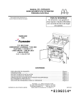
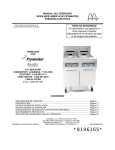
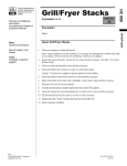
OPERATOR’S MANUAL
FRYMASTER BIPH14/MPH14 SERIES
ELECTRIC FRYER
This equipment chapter is to be
installed in the Fryer Section of the
Equipment Manual.
FOR YOUR SAFETY
Do Not Store or use gasoline or other
flammable vapors and liquids in the
vicinity of this or any other appliance.
MANUFACTURED
BY
P.O. BOX 51000
SHREVEPORT, LOUISIANA 71135-1000
PHONE: 1-318-865-1711
TOLL FREE: 1-800-551-8633
1-800-24 FRYER
FAX: 1-318-219-7135
TABLE OF CONTENTS
WARRANTY STATEMENT................................................................................................... Page i
INTRODUCTION................................................................................................................... Page 1-1
INSTALLATION INSTRUCTIONS ....................................................................................... Page 2-1
OPERATING INSTRUCTIONS ............................................................................................. Page 3-1
OPERATING THE BUILT-IN FILTRATION SYSTEM........................................................... Page 4-1
PREVENTIVE MAINTENANCE ............................................................................................ Page 5-1
OPERATOR TROUBLESHOOTING..................................................................................... Page 6-1
Frymaster L.L.C., 8700 Line Avenue 71106, 5489 Campus Drive 71129
P.O. Box 51000, Shreveport, Louisiana 71135-1000
PHONE 318-865-1711
FAX 318-219-7135
PRINTED IN THE UNITED STATES
SERVICE HOTLINE 1-800-24-FRYER
FEBRUARY 2005
*8195976*
NOTICE
DANGER
The front ledge of this appliance is not a step! Do not stand on the appliance. Serious
injury can result from slips or contact with the hot oil.
DANGER
Do not store or use gasoline or other flammable liquids or vapors in the vicinity of this or
any other appliance.
DANGER
The crumb tray in fryers equipped with a filter system must be emptied into a fireproof
container at the end of frying operations each day. Some food particles can spontaneously
combust if left soaking in certain shortening material.
WARNING
Do not bang fry baskets or other utensils on the fryer’s joiner strip. The strip is present to
seal the joint between the fry vessels. Banging fry baskets on the strip to dislodge
shortening will distort the strip, adversely affecting its fit. It is designed for a tight fit and
should only be removed for cleaning.
DANGER
Single fryers equipped with legs must be stabilized by installing anchor straps. All fryers
equipped with casters must be stabilized by installing restraining chains
WARNING
No structural material on the fryer should be altered or removed to accommodate placement
of the fryer under a hood. Questions? Call the Frymaster Dean Service Hotline at 1-800551-8633.
DANGER
Adequate means must be provided to limit the movement of this appliance without
depending on or transmitting stress to the electrical conduit. A restraint kit is provided with
the fryer. If the restraint kit is missing contact your local Frymaster Factory Authorized
Service Center (FASC) for part number 826-0900.
DANGER
This fryer has two power cords and prior to movement, testing, maintenance and any repair
on your Frymaster fryer; disconnect BOTH electrical power cords from the electrical power
supply.
NOTICE
All fryers shipped without factory supplied cords and plug assemblies must be hardwired
using flexible conduit to the terminal block located on the rear of the fryer. These fryers
should be wired to NEC specifications. Hardwired units must include installation of restraint
devices.
WARRANTY STATEMENT
Frymaster, L.L.C. makes the following limited warranties to the original purchaser only for this
equipment and replacement parts:
A. WARRANTY PROVISIONS - FRYERS
1. Frymaster L.L.C. warrants all components against defects in material and workmanship for a
period of one year.
2. All parts, with the exception of the frypot, heating elements and fuses, are warranted for one
year after installation date of fryer.
3. If any parts, except fuses, become defective during the first year after installation date,
Frymaster will also pay straight-time labor costs to replace the part, plus up to 100 miles/160
km of travel (50 miles/80 km each way).
B. WARRANTY PROVISIONS - FRYPOTS
(Applies to fryers manufactured after December 1, 2003, only.)
If a frypot develops a leak within ten years after installation, Frymaster will, at its option, either
replace the entire battery or replace the frypot, allowing up to the maximum time per the
Frymaster time allowance chart hours of straight-time labor plus up to 100 miles/160 km of
travel (50 miles/80 km each way) to change the frypot.
C. WARRANTY PROVISIONS - HEATING ELEMENTS
1. Frymaster L.L.C. warrants the heating elements against defective material or workmanship
for a period of three years from the original installation date, parts only.
2. This warranty does not cover ancillary components, including the hi-limit, temperature
probe, and contactors.
D. WARRANTY PROVISIONS - COOKING COMPUTER
1. Frymaster L.L.C. warrants the M-2000 Cooking Computer against defective material or
workmanship for a period of one year from the original installation date, parts and labor.
Replacements for defective units during the second and third year are available at a reduced
rate.
2. During this warranty period, Frymaster will, at its option, repair or replace defective cooking
computer returned with new or factory rebuilt and functionally operative units.
3. For replacement of defective computers under warranty, call your local Frymaster Factory
Authorized Service Center. All computers replaced under the Frymaster exchange program
are covered by a one-year (parts only) warranty.
i
E. PARTS RETURN
All defective in-warranty parts must be returned to a Frymaster Authorized Factory Service
Center within 60 days for credit. After 60 days, no credit will be allowed.
F. WARRANTY EXCLUSIONS
This warranty does not cover equipment that has been damaged due to misuse, abuse, alteration,
or accident such as:
•
improper or unauthorized repair (including any frypot which is welded in the field);
•
failure to follow proper installation instructions and/or scheduled maintenance procedures as
prescribed in your MRC cards. Proof of scheduled maintenance is required to maintain the
warranty;
•
improper maintenance;
•
damage in shipment;
•
abnormal use;
•
removal, alteration, or obliteration of either the rating plate or the date code on the heating
elements;
•
operating the frypot without shortening or other liquid in the frypot;
•
no fryer will be warranted under the seven-year program for which a proper start-up form has not
been received.
This warranty also does not cover:
•
transportation or travel over 100 miles/160 km (50 miles/80 km each way), or travel over two
hours;
•
overtime or holiday charges;
•
consequential damages (the cost of repairing or replacing other property which is damaged), loss
of time, profits, use or any other incidental damages of any kind.
There are no implied warranties of merchantability or fitness for any particular use or purpose.
ii
BIPH14 / MPH14 SERIES ELECTRIC FRYER
CHAPTER 1: INTRODUCTION
1.1
General
Read the instructions in this manual thoroughly before attempting to operate this equipment. This
manual covers all configurations of McDonald’s PH14 models. The fryers in this model family have
most parts in common, and when discussed as a group, will be referred to as “PH14” fryers.
Although similar in appearance to the BIH14 McDonald’s electric fryers, the BIPH14 fryers feature
a significantly different built-in filtration system. The new Euro-Look incorporates rounded topcaps
and large round drains, which ensures that fries and other debris will be washed into the filter pan.
Other features, including the deep cold-zones and easy to clean, open frypots remain essentially
unchanged. Other features, including the deep cold-zones and open frypots with tilt-up elements
remain essentially unchanged. The PH14 fryers are controlled with the M2000 computer. Fryers in
this series come in full- or split-vat arrangements, and can be purchased as single units or in batteries
of up to five fryers.
1.2
Safety Information
Before attempting to operate your unit, read the instructions in this manual thoroughly.
Throughout this manual, you will find notations enclosed in double-bordered boxes similar to the
one below.
DANGER
Hot cooking oil causes severe burns. Never attempt to move a fryer containing hot
cooking oil or to transfer hot cooking oil from one container to another.
CAUTION boxes contain information about actions or conditions that may cause or result in a
malfunction of your system.
WARNING boxes contain information about actions or conditions that may cause or result in
damage to your system, and which may cause your system to malfunction.
DANGER boxes contain information about actions or conditions that may cause or result in
injury to personnel, and which may cause damage to your system and/or cause your system to
malfunction.
Fryers in this series are equipped with the following automatic safety features:
1. Two high-temperature detection features shut off power to the elements should the temperature
controls fail.
2. A safety switch built into the drain valve prevents the elements from heating with the drain valve
even partially open.
1-1
1.3
Computer Information for the M2000 Computers
This equipment has been tested and found to comply with the limits for a Class A digital device,
pursuant to Part 15 of the FCC rules. While this device is a verified Class A device, it has been
shown to meet the Class B limits. These limits are designed to provide reasonable protection against
harmful interference when the equipment is operated in a commercial environment. This equipment
generates, uses and can radiate radio frequency energy and, if not installed and used in accordance
with the instruction manual, may cause harmful interference to radio communications. Operation of
the equipment in a residential area is likely to cause harmful interference in which case the user will
be required to correct the interference at his own expense.
The user is cautioned that any changes or modifications not expressly approved by the party
responsible for compliance could void the user's authority to operate the equipment.
If necessary, the user should consult the dealer or an experienced radio and television technician for
additional suggestions.
The user may find the following booklet prepared by the Federal Communications Commission
helpful: "How to Identify and Resolve Radio-TV Interference Problems". This booklet is available
from the U.S. Government Printing Office, Washington, DC 20402, Stock No. 004-000-00345-4.
1.4
European Community (CE) Specific Information
The European Community (CE) has established certain specific standards regarding equipment of
this type. Whenever a difference exists between CE and non-CE standards, the information or
instructions concerned are identified by means of shadowed boxes similar to the one below.
CE Standard
Example of box used to distinguish CE and
Non-CE specific information.
1.5
Installation, Operating, and Service Personnel
Operating information for Frymaster equipment has been prepared for use by qualified and/or
authorized personnel only, as defined in Section 1.7. All installation and service on Frymaster
equipment must be performed by qualified, certified, licensed, and/or authorized installation
or service personnel, as defined in Section 1.7.
1.6
Definitions
QUALIFIED AND/OR AUTHORIZED OPERATING PERSONNEL
Qualified/authorized operating personnel are those who have carefully read the information in this
manual and have familiarized themselves with the equipment functions, or who have had previous
experience with the operation of the equipment covered in this manual.
1-2
QUALIFIED INSTALLATION PERSONNEL
Qualified installation personnel are individuals, firms, corporations, and/or companies which, either
in person or through a representative, are engaged in and are responsible for the installation of gasfired appliances. Qualified personnel must be experienced in such work, be familiar with all gas
precautions involved, and have complied with all requirements of applicable national and local
codes.
QUALIFIED SERVICE PERSONNEL
Qualified service personnel are those who are familiar with Frymaster equipment and who have been
authorized by Frymaster, L.L.C. to perform service on the equipment. All authorized service
personnel are required to be equipped with a complete set of service and parts manuals, and to stock
a minimum amount of parts for Frymaster equipment. A list of Frymaster Factory Authorized
Service Centers (FASC) is included with the fryer when shipped from the factory. Failure to use
qualified service personnel will void the Frymaster warranty on your equipment
1.7
Shipping Damage Claim Procedure
What to do if your equipment arrives damaged:
Please note that this equipment was carefully inspected and packed by skilled personnel before
leaving the factory. The freight company assumes full responsibility for safe delivery upon
acceptance of the equipment.
1. File Claim for Damages Immediately, regardless of extent of damage.
2. Inspect For and Record All Visible Loss or Damage, and ensure that this information is noted
on the freight bill or express receipt and is signed by the person making the delivery.
3. Concealed Loss or Damage, that was unnoticed until equipment is unpacked should be recorded
and reported to the freight company or carrier immediately upon discovery. A concealed
damage claim must be submitted within 15 days of date of delivery. Be sure to retain container
for inspection.
Frymaster
DOES NOT ASSUME RESPONSIBILITY FOR DAMAGE OR LOSS
INCURRED IN TRANSIT.
1-3
1.8
Service Information
For non-routine maintenance or repairs, or for service information, contact your local Frymaster
Authorized Service Center (FASC). In order to assist you quickly, the Frymaster Factory
Authorized Service Center (FASC) or Service Department representative requires certain
information about your equipment. Most of this information is printed on a data plate affixed to the
inside of the fryer door. Part numbers are found in the Installation, Operation, Service, and Parts
Manual. Parts orders may be placed directly with your local FASC or distributor. Included with
fryers when shipped from the factory is a list of Frymaster FASCs. If you do not have access to this
list, contact the Frymaster Service Department at 1-800-551-8633 or 1-318-865-1711.
The following information will be needed in order to assist you efficiently:
Model Number_________________________
Serial Number _________________________
Voltage ______________________________
Nature of the Problem ___________________
____________________________________
____________________________________
RETAIN AND STORE THIS MANUAL IN A SAFE PLACE FOR FUTURE USE.
1-4
BIPH14 / MPH14 SERIES ELECTRIC FRYER
CHAPTER 2: INSTALLATION INSTRUCTIONS
2.1
General Installation Requirements
Qualified, licensed, and/or authorized installation or service personnel, as defined in Section
1.6 of this manual, should perform all installation and service on Frymaster equipment.
Failure to use qualified, licensed, and/or authorized installation or service personnel (as
defined in Section 1.6 of this manual) to install or otherwise service this equipment will void
the Frymaster warranty and may result in damage to the equipment or injury to personnel.
Where conflicts exist between instructions and information in this manual and local or
national codes or regulations, installation and operation shall comply with the codes or
regulations in force in the country in which the equipment is installed.
Service may be obtained by contacting your local Factory Authorized Service Center.
NOTICE
If this equipment is wired directly into the electrical power supply, a means for
disconnection from the supply having a contact separation of at least 3-mm in all
poles must be incorporated in the fixed wiring.
NOTICE
This equipment must be positioned so that the plug is accessible unless other
means for disconnection from the power supply (e.g., a circuit breaker) is provided.
NOTICE
If this appliance is permanently connected to fixed wiring, it must be connected by
means of copper wires having a temperature rating of not less than 167°F (75°C).
NOTICE
If the electrical power supply cord is damaged, it must be replaced by a Frymaster
Dean Factory Authorized Service Center technician or a similarly qualified person in
order to avoid a hazard.
DANGER
This appliance must be connected to a power supply having the same voltage and
phase as specified on the rating plate located on the inside of the appliance door.
DANGER
All wiring connections for this appliance must be made in accordance with the
wiring diagram(s) furnished with the appliance. Refer to the wiring diagram(s)
affixed to the inside of the appliance door when installing or servicing this
equipment.
2-1
DANGER
Frymaster appliances equipped with legs are for stationary installations. Appliances
fitted with legs must be lifted during movement to avoid damage to the appliance
and bodily injury. For movable installations, optional equipment casters must be
used. Questions? Call 1-800-551-8633.
DANGER
Do not attach an apron drainboard to a single fryer. The fryer may become unstable,
tip over, and cause injury. The appliance area must be kept free and clear of
combustible material at all times.
DANGER
Building codes prohibit a fryer with its open tank of hot oil being installed beside an
open flame of any type, including those of broilers and ranges.
In the event of a power failure, the fryer(s) will automatically shut down. If this occurs, turn the
power switch OFF. Do not attempt to start the fryer(s) until power is restored.
This appliance must be kept free and clear of combustible material, except that it may be installed on
combustible floors.
A clearance of 6 inches (15cm) must be provided at both sides and back adjacent to combustible
construction. A minimum of 24 inches (61cm) should be provided at the front of the equipment for
servicing and proper operation.
WARNING
Do not block the area around the base or under the fryers.
2.1.2 Electrical Grounding Requirements
All electrically operated appliances must be grounded in accordance with all applicable national and
local codes, and, where applicable, CE codes. A wiring diagram is located on the inside of the fryer
door. Refer to the rating plate on the inside of the fryer door for proper voltages.
DANGER
This appliance is equipped with a three-prong (grounding) plug for your protection
against electrical shock, and must be plugged directly into a properly grounded
three-prong receptacle. Do not cut, remove, or otherwise bypass the grounding
prong on this plug!
WARNING
To ensure the safe and efficient operation of the fryer and hood, the electrical plug
for the 120-volt line, which powers the hood, must be fully engaged and locked in its
pin and sleeve socket.
2.1.3 Australian Requirements
To be installed in accordance with AS 5601 / AG 601, local authority, gas, electricity, and any other
relevant statutory regulations.
2-2
2.2
Power Requirements
AMPS PER LEG
VOLTAGE
208
PHASE
3
WIRE
SERVICE
3
MIN.
SIZE
6
AWG
(mm2)
(16)
L1
39
L2
39
L3
39
240
3
3
6
(16)
34
34
34
480
3
3
8
(10)
17
17
17
220/380
3
4
6
(16)
21
21
21
240/415
3
4
6
(16)
20
20
21
230/400
3
4
6
(16)
21
21
21
The three phase supply plug for the elements is rated at 60 amps, 250 VAC and is NEMA
configuration L15-60P. The control and filter plug is rated at 20 amps, 120/208 VAC and is NEMA
configuration L21-20P. Each fryer should have its cord for the element supply on an individual
circuit as well as the control cord.
NOTICE
If this appliance is permanently connected to fixed wiring, it must be connected by
means of copper wires having a temperature rating of not less than 167°F (75°C).
DANGER
This appliance must be connected to a power supply having the same voltage and
phase as specified on the rating plate located on the inside of the appliance door.
DANGER
All wiring connections for this appliance must be made in accordance with the
wiring diagram(s) furnished with the appliance. Refer to the wiring diagram(s)
affixed to the inside of the appliance door when installing or servicing this
equipment.
2.3
After Fryers Are Positioned At the Frying Station
DANGER
No structural material on the fryer should be altered or removed to accommodate
placement of the fryer under a hood. Questions? Call the Frymaster/Dean Service
Hotline at 1-800-551-8633.
1. Once the fryer has been positioned at the frying station, use a carpenter’s level placed across the
top of the frypot to verify that the unit is level, both side-to-side and front-to-back.
To level fryers, adjust the casters being careful to ensure the fryer(s) are at the proper height in
the frying station.
When the fryer is leveled in its final position, install the restraints provided with the unit to limit
its movement so that it does not depend on or transmit stress to the electrical conduit or
connection. Install the restraints in accordance with the provided instructions (see illustration on
the following page). If the restraints are disconnected for service or other reasons, they must be
reconnected before the fryer is used.
2-3
DANGER
Hot oil can cause severe burns. Avoid contact. Under all circumstances, oil must be
removed from the fryer before attempting to move it to avoid spills, falls, and severe
burns. Fryers may tip and cause personal injury if not secured in a stationary
position.
2. Close fryer drain-valve(s) and fill frypot with water to the bottom oil level line.
3. Boil out frypot(s) in accordance with the instructions in Section 5.1.4 of this manual.
4. Drain, clean, and fill frypot(s) with cooking oil.
Procedures in Chapter 3.)
2-4
(See Equipment Setup and Shutdown
BIPH14 / MPH14 SERIES ELECTRIC FRYER
CHAPTER 3: OPERATING INSTRUCTIONS
3.1 Equipment Setup and Shutdown Procedures
Setup
DANGER
Never operate the appliance with an empty frypot. The frypot must be filled with
water or vegetable oil before energizing the elements. Failure to do so will result in
irreparable damage to the elements and may cause a fire.
DANGER
Remove all drops of water from the frypot before filling with vegetable oil. Failure to
do so will cause spattering of hot liquid when the oil is heated to cooking
temperature.
1. Fill the frypot with vegetable oil to the bottom OIL LEVEL line located on the rear of the frypot.
This will allow for oil expansion as heat is applied. Do not fill cold oil any higher than the
bottom line; overflow may occur as heat expands the oil.
2. Ensure that the power cord(s) is/are plugged into the appropriate receptacle(s). Verify that the
face of the plug is flush with the outlet plate, with no portion of the prongs visible.
3. Ensure that the oil level is at the top OIL LEVEL line when the oil is at its cooking temperature.
It may be necessary to add oil to bring the level up to the proper mark, after it has reached
cooking temperature.
Shutdown
1. Turn the fryer off.
2. Filter the vegetable oil and clean the fryers (See Chapters 4 and 5).
3. Place the frypot covers on the frypots.
3.2 Operation
If this is the first time the fryer is being used, refer to the frypot boil-out procedure on Page 5-2.
This fryer is equipped with M2000 computers (illustrated below). Refer to the separate M2000
Computer Operating Instructions furnished with the fryer for the computer programming and
operating procedures.
M2000 COMPUTER
Refer to Chapter 4 of this manual for operating instructions for the built-in filtration system.
3–1
BIPH14 / MPH14 SERIES ELECTRIC FRYER
CHAPTER 4: FILTRATION INSTRUCTIONS
4.1
Introduction
The FootPrint Pro filtration system allows the oil in one frypot to be safely and efficiently filtered
while the other frypots in a battery remain in operation.
Section 4.2 covers preparation of the filter system for use. Operation of the system is covered in
section 4.3.
WARNING
The on-site supervisor is responsible for ensuring that operators are made aware of
the inherent hazards of operating a hot oil filtering system, particularly the aspects
of oil filtration, draining and cleaning procedures.
4.2
Preparing the Filter for Use
1. Pull the filter pan out from the cabinet
and remove the crumb tray, hold-down
ring, filter pad (or paper), and filter
screen.
(See Figure 1) Clean all metal parts with
a solution of All Purpose Concentrate
and hot water then dry thoroughly.
Screen
Filter Pad or
Filter Paper
Crumb Tray
The filter pan is equipped with rollers in
rails, much like a kitchen drawer. The
pan can be removed from the cabinet for
cleaning by lifting the front of the pan to
disengage the front rollers, then pulling
it forward until the rear rollers clear the
rails. The pan cover must not be
removed except for cleaning, interior
access, or to allow a shortening disposal
unit (MSDU) to be positioned under the
drain.
2. Inspect the filter pan connection fitting
to ensure that both o-rings are in good
condition. (See Figure 2)
Hold-Down Ring
Figure 1
Inspect the filter
connection fitting
O-rings.
Figure 2
4-1
3. Then in reverse order, place the metal filter screen in the center of the bottom of the pan, then lay
a filter pad over the screen, ensuring that the rough side of the pad is up. Make sure that the pad
is in between the embossed ridges of the filter pan. Then position the hold down ring on top of
the pad. If using filter paper, lay a sheet of filter paper over the top of the pan overlapping on all
sides. Position the hold down ring over the filter paper and lower the ring into the pan, allowing
the paper to fold up and around the ring as it is pushed to the bottom of the pan. Then sprinkle 8ounces of filter powder over the filter paper.
4.
Reinstall the crumb tray at the front of the pan. (See Figure 1)
DO NOT USE FILTER POWDER WITH THE PAD!
5. Push the filter pan back into the fryer, positioning it all the way to the back of the cabinet. The
filtration system is now ready for use.
4.3
Operation of the Filter
DANGER
Draining and filtering of oil must be accomplished with care to avoid the possibility
of a serious burn caused by careless handling. The oil to be filtered is at or near
350°F (177°C). Ensure drain handles are in their proper position before operating
any switches or valves. Wear all appropriate safety equipment when draining and
filtering oil.
DANGER
NEVER attempt to drain oil from the fryer with the elements energized! Doing so will
cause irreparable damage to the elements and may cause a flash fire. Doing so will
also void the Frymaster warranty.
1. Turn the fryer power OFF. Drain the frypot into the filter pan. If necessary, use the Fryer's
Friend clean-out rod to clear the drain from inside the frypot.
Open drain valves
by rotating to the
right.
Open the drain valves on the frypot
and drain the oil into the filter pan.
DANGER
Do not drain more than one frypot at a time into the built-in filtration unit to avoid
overflow and spillage of hot oil.
4-2
DANGER
NEVER attempt to clear a clogged drain valve from the front of the valve! Hot oil will
rush out creating the potential for severe burns.
DO NOT hammer on the drain valve with the cleanout rod or other objects. Damage
to the ball inside will result in leaks and will void the Frymaster warranty.
Open valve by moving
handle to the right.
2. After the oil has drained from the frypot,
turn the filter handle to the ON position
to start the pump and begin the filtering
process. There may be a slight delay
before the pump activates.
Turn the filter handle to the ON position.
3. The filter pump draws the oil through the filter pad and screen and circulates it back up to and
through the frypot during a 5-minute process called polishing. Polishing cleans the oil by
trapping solid particles in the filter pad.
4. After the oil is filtered (about 5 minutes), close the drain valve and allow the fryer to refill. Let
the filter pump run 10 to 12 seconds after the oil begins to bubble in the frypot then turn the filter
off.
WARNING
The filter pump is equipped with a manual reset switch (see photo below) in case the
filter motor overheats or an electrical fault occurs. If this switch trips, turn off power
to the filter system and allow the pump motor to cool 20 minutes before attempting
to reset the switch.
Filter Pump Reset Switch
5. Lower the elements into the frypot and reinstall the basket support rack.
6. Ensure the drain valve is fully closed. (If the drain valve is not fully closed, the fryer will not
operate.) Turn the fryer ON and allow the oil to reach setpoint.
4-3
DANGER
The crumb tray in fryers equipped with a filter system must be emptied into a
fireproof container at the end of frying operations each day. Some food particles can
spontaneously combust if left soaking in certain shortening material.
WARNING
Do not bang fry baskets or other utensils on the fryer’s joiner strip. The strip is
present to seal the joint between the fry vessels. Banging fry baskets on the strip to
dislodge shortening will distort the strip, adversely affecting its fit. It is designed for
a tight fit and should only be removed for cleaning.
4.4
Draining and Disposing of Waste Oil
When your cooking oil/shortening has reached the end of its usable life, drain the oil/shortening into
an appropriate container for transport to the disposal container. Frymaster recommends the use of
the McDonald’s Shortening Disposal Unit (MSDU). NOTE: If using an MSDU built before January
2004 the filter pan cover on must be removed to allow the unit to be positioned beneath the drain. To
remove the lid, lift up on the front edge and pull it straight out of the cabinet. Refer to the
documentation furnished with your disposal unit for specific operating instructions. If a shortening
disposal unit is not available, allow the oil/shortening to cool to 100°F (38°C), then drain the oil or
shortening into a metal stockpot or similar metal container. When draining is finished, close the
fryer drain valve securely.
DANGER
Allow oil/shortening to cool to 100°F (38°C) before draining into an appropriate
container for disposal.
When draining oil/shortening into a disposal unit, do not fill above the maximum fill
line located on the container.
4-4
BIPH14 / MPH14 SERIES ELECTRIC FRYER
CHAPTER 5: PREVENTATIVE MAINTENANCE
5.1
Cleaning the Fryer
DANGER
The crumb tray in fryers equipped with a filter system must be emptied into a
fireproof container at the end of frying operations each day. Some food particles
can spontaneously combust if left soaking in certain shortening material.
DANGER
Never attempt to clean the fryer during the frying process or when the frypot is filled
with hot oil. If water comes in contact with oil heated to frying temperature, it will
cause spattering of the oil, which can result in severe burns to nearby personnel.
WARNING
Use McDonald’s All Purpose Concentrate. Read the directions for use and
precautionary statements before use. Particular attention must be paid to the
concentration of cleaner and the length of time the cleaner remains on the foodcontact surfaces.
5.1.1
Clean Inside and Outside of the Fryer Cabinet – Daily
Clean inside the fryer cabinet with a dry, clean cloth. Wipe all accessible metal surfaces and
components to remove accumulated oil and dust.
Clean the outside of the fryer cabinet with a clean, damp cloth soaked with McDonald’s All Purpose
Concentrate. Wipe with a clean, damp cloth.
5.1.2
Clean the Built-in Filtration System – Daily
WARNING
Never drain water into the filter pan. Water will damage the filter pump.
There are no periodic preventive maintenance checks and services required for your FootPrint Pro
Filtration System other than daily cleaning of the filter pan and associated components with a
solution of hot water and McDonald’s All Purpose Concentrate.
5.1.3
Clean Behind Fryers – Weekly
Clean behind fryers in accordance with the procedure detailed in maintenance requirement card
(MRC) 14A.
WARNING
To ensure the safe and efficient operation of the fryer and hood, the electrical plug
for the 120-volt line, which powers the hood, must be fully engaged and locked in its
pin and sleeve socket.
5–1
5.1.4
Clean the Frypot and Heating Elements – Weekly
DANGER
Never operate the appliance with an empty frypot. The frypot must be filled with
water or vegetable oil before energizing the elements. Failure to do so will result in
irreparable damage to the elements and may cause a fire.
Boiling-Out the Frypot
Before the fryer is first used, it should be boiled out to ensure that residue from the manufacturing
process has been eliminated. Also, after the fryer has been in use for a period of time, a hard film of
caramelized vegetable oil/shortening will form on the inside of the frypot. This film should be
periodically removed by following the boil-out procedure contained in maintenance requirement
card (MRC) 14A. Refer to the separate M2000 Computer Operating Instructions furnished with the
fryer for specific details on setting up the computer for boil-out operation.
5.1.5
Clean Detachable Parts and Accessories – Weekly
Wipe all detachable parts and accessories with a clean, dry cloth. Use a clean cloth saturated with a
solution of McDonald’s All Purpose Concentrate to remove accumulated carbonized oil/shortening
on detachable parts and accessories. Rinse the parts and accessories thoroughly with clean water and
wipe dry before reinstalling.
5.2
Annual/Periodic System Inspection
This appliance should be inspected and adjusted periodically by qualified service personnel as part
of a regular kitchen maintenance program.
Frymaster recommends that a Factory Authorized Service Technician inspect this appliance at least
annually as follows:
Fryer
●
Inspect the cabinet inside and out, front and rear for excessive oil build-up and/or oil migration.
●
Verify that the heating element wires are in good condition and that leads have no visible fraying
or insulation damage and that they are free of oil migration build-up.
●
Verify that heating elements are in good condition with no carbon/caramelized oil build-up.
Inspect the elements for signs of extensive dry-firing.
Verify that the tilt mechanism is working properly when lifting and lowering elements and that
the element wires are not binding and/or chafing.
● Verify the heating-element amp-draw is within the allowed range as indicated on the appliance’s
rating plate.
●
●
Verify that the temperature and high-limit probes are properly connected, tightened and
functioning properly, and that mounting hardware and probe guards are present and properly
installed.
5–2
●
Verify that component box and contactor box components (i.e. computer/controller, relays,
interface boards, transformers, contactors, etc.) are in good condition and free from oil migration
build-up and other debris.
●
Verify that component box and contactor box wiring connections are tight and that wiring is in
good condition.
●
Verify that all safety features (i.e. contactor shields, drain safety switches, reset switches, etc.)
are present and functioning properly.
●
Verify that the frypot is in good condition and free of leaks and that the frypot insulation is in
serviceable condition.
●
Verify that all wiring harnesses and connections are tight and in good condition.
Built-In Filtration System
●
Inspect all oil-return and drain lines for leaks and verify that all connections are tight.
●
Inspect the filter pan for leaks and cleanliness. If there is a large accumulation of crumbs in the
crumb basket, advise the owner/operator that the crumb basket should be emptied into a fireproof
container and cleaned daily.
●
Verify that all O-rings and seals are present and in good condition. Replace o-rings and seals if
worn or damaged.
●
Check filtration system integrity as follows:
□ With the filter pan empty, place each oil return handle, one at a time, in the ON position.
Verify that the pump activates and that bubbles appear in the vegetable oil.
□ Close all oil return valves (i.e., place all oil return handles in the OFF position). Verify
proper functioning of each oil return valve by activating the filter pump using the lever on
one of the oil return handle microswitches. No air bubbles should be visible in any frypot.
□ Verify that the filter pan is properly prepared for filtering, then drain a frypot of oil heated to
335°F (168°C) into the filter pan and close the frypot drain valve. Place the oil return handle
in the ON position. Allow all vegetable oil to return to the frypot (indicated by bubbles in the
vegetable oil). Return the oil return handle to the OFF position. The frypot should have
refilled in no more than 2 minutes and 30 seconds.
5-3
BIPH14 / MPH14 SERIES ELECTRIC FRYER
CHAPTER 6: OPERATOR TROUBLESHOOTING
6.1 Introduction
This section provides an easy reference guide to some of the common problems that may occur
during the operation of this equipment. The troubleshooting guides that follow are intended to help
correct, or at least accurately diagnose, problems with this equipment. Although the chapter covers
the most common problems reported, you may encounter problems that are not covered. In such
instances, the Frymaster Technical Services staff will make every effort to help you identify and
resolve the problem.
When troubleshooting a problem, always use a process of elimination starting with the simplest
solution and working through to the most complex. Never overlook the obvious – anyone can forget
to plug in a cord or fail to close a valve completely. Most importantly, always try to establish a clear
idea of why a problem has occurred. Part of any corrective action involves taking steps to ensure
that it doesn’t happen again. If a controller malfunctions because of a poor connection, check all
other connections, too. If a fuse continues to blow, find out why. Always keep in mind that failure
of a small component may often be indicative of potential failure or incorrect functioning of a more
important component or system.
Before calling a service agent or the Frymaster HOTLINE (1-800-24-FRYER):
•
Verify that electrical cords are plugged in and that circuit breakers are on.
•
Verify that frypot drain valves are fully closed.
•
Have your fryer’s model and serial numbers ready to give to the technician assisting
you.
DANGER
Hot oil will cause severe burns. Never attempt to move this appliance when filled
with hot oil or to transfer hot oil from one container to another.
DANGER
This equipment should be unplugged when servicing, except when electrical circuit
tests are required. Use extreme care when performing such tests.
This appliance may have more than one electrical power supply connection point.
Disconnect all power cords before servicing.
Inspection, testing, and repair of electrical components should be performed by an
authorized service agent only.
6-1
6.2
Troubleshooting
6.2.1 Computer and Heating Problems
Problem
Probable Causes
A. Computer not turned on.
B. No Power to the fryer.
No Display on
Computer.
C. Computer has failed.
Corrective Action
A. Press the ON/Off switch to turn
the computer on.
B. This fryer has two cords: a
computer power cord and a main
power cord. If the computer
cord is not plugged in, the
computer will not activate.
Verify computer power cord is
plugged in and that circuit
breaker is not tripped.
C. Call FASC.
D. Damaged computer wiring harness D. Call FASC
E. Power supply component or
interface board has failed.
A. Drain valve is open.
B. Computer has failed.
Fryer does not heat.
C. Main power cord not plugged in.
6-2
F. If any component in the power
supply system (including the
transformer and interface board)
fail, power will not be supplied
to the computer and it will not
function. Determining which
component has failed is beyond
the scope of operator
troubleshooting. Call FASC.
A. A drain safety switch prevents
the heating element from being
energized if the drain valve is
not fully closed. Verify that the
drain valve is fully closed.
B. Call FASC.
C. This fryer has two cords: a
120V power cord and the main
3-phase power cord. If the 120V
power cord is plugged in but the
main power cord is not, the
computer will appear to work
normally, but the fryer will not
heat. Verify that both the main
power cord and 120V is fully
seated in its receptacle, locked
into place and that circuit
breaker is not tripped.
Problem
Continued from
previous page.
Fryer does not heat
after filtering.
Fryer heats until
high limit trips with
heat indicator ON.
Fryer heats until
high limit trips
without heat
indicator ON.
Fryer stops heating
with heat indicator
ON.
Probable Causes
D. One or more other components
have failed.
Drain valve is open.
Corrective Action
D. If the circuitry in the fryer
control system cannot determine
the frypot temperature, the
system will not allow the
element to be energized or will
de-energize the element if it is
already energized. If the
contactor, element, or associated
wiring fails, the element will not
energize. Determining which
specific component is
malfunctioning is beyond the
scope of operator
troubleshooting. Call FASC.
This fryer is equipped with a drain
safety switch that prevents the
heating element from being
energized if the drain valve is not
fully closed. Verify that the drain
valve is fully closed.
Temperature probe or computer has
failed.
Call FASC.
Contactor or computer has failed
Call FASC.
The high limit thermostat or
contactor has failed.
6-3
The fact that the heat indicator is
ON indicates that the computer is
functioning properly and is calling
for heat. The high limit thermostat
functions as a normally closed
switch. If the thermostat fails, the
"switch" opens and power to the
elements is shut off. If the
contactor fails to close, no power is
supplied to the elements.
Determining which component has
failed is beyond the scope of
operator troubleshooting.
Call FASC.
6.2.2 Error Messages and Display Problems
Problem
M2000 display is in
wrong temperature
scale (Fahrenheit or
Celsius).
Probable Causes
Incorrect display option
programmed.
M2000 display
shows HI.
Fryer is 15ºF (8ºC) above setpoint.
M2000 display
shows HOT.
Frypot temperature is more than
410ºF (210ºC) or, in CE countries,
395ºF (202ºC).
M2000 display
shows LOW TEMP.
Frypot temperature is between
180°F (82°C) and 315°F (157°C).
M2000 display
shows PROBE
FAILURE.
Problem with the temperature
measuring circuitry including the
probe.
M2000 display
shows IGNITION
FAILURE.
Open drain valve, failed computer,
failed transformer, open high-limit
thermostat.
M2000 display
shows HI-LIMIT.
Computer in hi-limit test mode.
6-4
Corrective Action
M2000 computers may be
programmed to display in either
Fahrenheit or Celsius. Refer to the
separate M2000 Computer Operation
Manual for instructions on changing
the display.
This display will appear only if the
fryer is in the non-dedicated mode
and the frypot temperature rises 15°
(8°C) or more above the
programmed setpoint. This indicates
a problem with the temperature
control circuitry. Turn the fryer off
and call FASC.
This in an indication of a
malfunction in the temperature
control circuitry, including a failure
of the high limit thermostat. Shut
the fryer down immediately and call
FASC.
This display is normal when the
fryer is first turned on and may
appear for a short while if a large
batch of frozen product is added to
the frypot. If the display never goes
out, the fryer is not heating. Shut the
fryer down and call FASC.
This indicates a problem within the
temperature measuring circuitry that
is beyond the scope of operator
troubleshooting. Shut the fryer
down and call FASC.
This indicates that the fryer is not
heating. It is displayed if the fryer
loses its ability to heat oil. It is also
displayed when the oil temperature is
above 450°F (232°C) and the highlimit thermostat has opened, halting
the heating of the oil. Verify that the
drain valves are fully closed. If this
does not correct the problem, call
your FASC.
This is displayed only during a test
of the hi-limit circuit and indicates
that the hi-limit has opened properly.
Problem
M2000 display
shows HI 2 BAD.
Display shows
with alarm
sounding.
Display shows
with alarm
sounding. Heating
indicator is on, but
no heat.
Display shows ,
heating indicator
cycles on and off
normally.
Probable Causes
Computer in hi-limit test mode.
This is displayed only during a test
of the hi-limit circuit and indicates
that the hi-limit has failed. DO NOT
OPERATE THE FRYER! Call
FASC.
Damaged computer wiring
harness or connector.
Call FASC
A. Drain valve not fully closed.
A. Failed computer.
B. Damaged
harness.
Display shows
and alarm
sounds, but fryer
operates normally
(false alarm).
Computer will not
go into program
mode or some
buttons do not
actuate.
Heat indicator off
upon initial startup.
Display shows
or
with alarm
sounding.
Corrective Action
A. Press the ON/OFF switch off,
close
the
drain
valve(s)
completely, then press the
ON/OFF switch on.
Call FASC.
computer
Failed computer.
wiring
Call FASC.
Call FASC.
Failed computer.
Call FASC.
Failed computer.
Call FASC.
6-5
Problem
Continued from
previous page.
Probable Causes
Corrective Action
B. In order to properly filter, the
oil or shortening should be at
or near 350ºF (177ºC). At
temperatures lower than this,
the oil/shortening becomes too
thick to pass through the filter
B. Attempting to filter with oil or
medium easily, resulting in
shortening that is not hot enough.
much slower oil return and
eventual overheating of the
filter pump motor. Make sure
oil/shortening is at or near
frying temperature before
draining oil into filter pan.
6-7