1
© Copyright HT-ITALIA 2012
Release 1.07 - 20/02/12
Manuale d'Uso
User’s manual
Manual de instrucciones
Bedienungsanleitung
QuickLAN 6055
Indice generale
General index
Índice general
Inhalt
ITALIANO ......................... IT - 1
ENGLISH ......................... EN - 1
ESPAÑOL ........................ ES - 1
DEUTSCH ........................ DE - 1
ITALIANO
Manuale d’uso
© Copyright HT-ITALIA 2012
Versione IT 1.07 - 20/02/12
QuickLAN 6055
INDICE:
1. ISTRUZIONI PRELIMINARI E SICUREZZA ................................................................ 2
1.1.
1.2.
1.3.
1.4.
2.
3.
DESCRIZIONE DELLO STRUMENTO ........................................................................ 3
PREPARAZIONE ALL’UTILIZZO ................................................................................ 4
3.1.
3.2.
3.3.
3.4.
3.5.
3.6.
4.
Istruzioni preliminari .............................................................................................................2
Durante l’uso ........................................................................................................................2
Dopo l’uso ............................................................................................................................2
Fine vita ...............................................................................................................................2
Generalita ............................................................................................................................4
Controlli iniziali .....................................................................................................................4
Alimetazione dello strumento ...............................................................................................4
Taratura ...............................................................................................................................4
Immagazzinamento ..............................................................................................................4
Pulizia dello strumento .........................................................................................................4
ISTRUZIONI OPERATIVE ............................................................................................ 5
4.1.
Descrizione dello strumento .................................................................................................5
4.1.1.
4.1.2.
4.1.3.
5.
MISURE........................................................................................................................ 6
5.1.
5.2.
5.3.
6.
Verifica del cablaggio ...........................................................................................................6
Nota esplicativa sulla condizione di errore Split Pairs..........................................................7
Condizioni di errore ..............................................................................................................8
SPECIFICHE TECNICHE ............................................................................................. 9
6.1.
Caratteristiche tecniche........................................................................................................9
6.1.1.
6.1.2.
6.2.
6.3.
Caratteristiche meccaniche ......................................................................................................... 9
Caratteristiche meccaniche degli identificatori remoti ................................................................. 9
Alimentazione .............................................................................................................................. 9
Ambiente ..............................................................................................................................9
6.3.1.
6.4.
Connettori .................................................................................................................................... 9
Cavi controllabili .......................................................................................................................... 9
Caratteristiche generali ........................................................................................................9
6.2.1.
6.2.2.
6.2.3.
Condizioni ambientali di utilizzo................................................................................................... 9
Accessori .............................................................................................................................9
6.4.1.
6.4.2.
7.
Descrizione dei comandi ............................................................................................................. 5
Accensione dello strumento ........................................................................................................ 5
Selezione del tipo di cavo ............................................................................................................ 5
Accessori standard ...................................................................................................................... 9
Accessori opzionali ...................................................................................................................... 9
ASSISTENZA ............................................................................................................. 10
7.1.
7.2.
Condizioni di garanzia ........................................................................................................10
Assistenza ..........................................................................................................................10
IT - 1
QuickLAN 6055
1. ISTRUZIONI PRELIMINARI E SICUREZZA
ATTENZIONE
Per la vostra sicurezza e per quella dello strumento è raccomandato di
seguire quanto descritto in questo manuale di istruzioni leggendo con
scrupolosa attenzione le note precedute dal simbolo .
Il mancato rispetto delle istruzioni e/o di quanto riportato nelle parti
evidenziate con la scritta ATTENZIONE può danneggiare l’apparato e
mettere a rischio l’incolumità delle persone.
1.1.
ISTRUZIONI PRELIMINARI
• Prima dell’utilizzo leggere attentamente il presente manuale di istruzioni.
• Ogni istruzione preceduta dal simbolo
deve essere osservata in maniera scrupolosa
onde evitare incidenti o danni.
• Controllare che la batteria sia stata inserita correttamente.
• Questo prodotto deve esserE usato esclusivamente da personale qualificato ed in
grado di applicare le giuste precauzioni di sicurezza.
• Non eseguire alcuna misura in condizioni al di fuori dei limiti specificati nel presente
manuale.
ATTENZIONE
Collegare QuickLAN 6055 solo su cavi inattivi, collegamenti a linee
telefoniche o reti dati attive possono danneggiare lo strumento.
1.2.
DURANTE L’USO
Leggere accuratamente le seguenti raccomandazioni e precauzioni d’uso:
ATTENZIONE
Qualora il display dello strumento mostri il simbolo “
” occorre
interrompere le misure e sostituire la batteria. Non sostituire mai la batteria
mentre lo strumento è installato sul conduttore.
•
•
•
•
•
Non usare lo strumento se danneggiato.
Non utilizzare QuickLAN 6055 all’aperto.
Non utilizzare lo strumento ad altitudini oltre i 2000 metri sul livello del mare.
Non effettuare misure in condizioni ambientali al di fuori delle limitazioni indicate nel
paragrafo 6.3.1.
Non esporre QuickLAN 6055 a schizzi d’acqua.
1.3. DOPO L’USO
• Spegnere lo strumento dopo l’uso.
• Qualora lo strumento non venga utilizzato per un lungo periodo, rimuovere la batteria.
1.4.
FINE VITA
ATTENZIONE: il simbolo riportato indica che l'apparecchiatura ed i suoi
accessori devono essere raccolti separatamente e trattati in modo corretto
IT - 2
QuickLAN 6055
2. DESCRIZIONE DELLO STRUMENTO
Gentile Cliente, La ringraziamo per aver scelto uno strumento del nostro programma di
vendita. Il dispositivo da Lei appena acquistato, se utilizzato secondo quanto descritto nel
presente manuale, Le garantirà misure accurate ed affidabili.
QuickLAN 6055 è un facile ed efficace tester per cablaggi strutturati di qualunque
categoria (CAT 5, CAT 5E, CAT 6, CAT 7, ecc.). Lo strumento può individuare interruzioni
nel cavo ed errori di cablaggio di cavi UTP (Unshielded Twisted Pair cable), e STP
(Shielded – screened shielded Twisted Pair cable).
QuickLAN 6055 non solo individua l’errore nel cablaggio singolo, come cavi interrotti o
cortocircuitati, coppie invertite o male accoppiate, ma testa anche fino a otto cavi
contemporaneamente grazie alle otto unità remote numerate (#1 e #2 di serie, #3 - #8
opzionali).
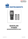
Fig. 1: Strumento ed unità remote #1 e #2
IT - 3
QuickLAN 6055
3. PREPARAZIONE ALL’UTILIZZO
3.1.
GENERALITA
Lo strumento da Lei acquistato è uno strumento di precisione. Durante l’utilizzo e
l’immagazzinamento rispettare le raccomandazioni elencate in questo manuale per evitare
possibili danni o pericoli durante l’utilizzo. Non utilizzare lo strumento in ambienti
caratterizzati da elevato tasso di umidità o temperatura elevata. Non esporre direttamente
alla luce del sole. Spegnere sempre lo strumento dopo l’utilizzo. Se si prevede di non
utilizzarlo per un lungo periodo rimuovere la batteria per evitare fuoruscite di liquidi da
parte di quest’ultima che possano danneggiare i circuiti interni dello strumento.
3.2.
CONTROLLI INIZIALI
Lo strumento, prima di essere spedito, è stato controllato dal punto di vista elettrico e
meccanico. Sono state prese tutte le precauzioni possibili affinché lo strumento potesse
essere consegnato senza danni.
Si consiglia comunque di controllare sommariamente lo strumento per accertare eventuali
danni subiti durante il trasporto. Se si dovessero riscontrare anomalie contattare
immediatamente la società HT Italia ed il proprio rivenditore.
Si consiglia inoltre di controllare che l’imballo contenga tutte le parti indicate al paragrafo
6.4.1. In caso di discrepanze contattare il rivenditore. Qualora fosse necessario restituire
lo strumento, si prega di seguire le istruzioni riportate al paragrafo 7.
3.3.
ALIMETAZIONE DELLO STRUMENTO
Lo strumento è alimentato a batteria per la cui autonomia e tipo si veda il paragrafo 6.2.3.
Qualora il display dello strumento mostri il simbolo di batteria scarica (vedi paragrafo
6.2.3) occorre interrompere le misure e sostituire la batteria. Non sostituire mai la batteria
mentre lo strumento è collegato all’impianto.
ATTENZIONE
Solo tecnici qualificati possono effettuare questa operazione. Prima di
effettuare questa operazione assicurarsi di aver rimosso tutti i cavi dai
terminali di ingresso.
1.
2.
3.
4.
Spegnere lo strumento e rimuovere il cavo dal terminale di ingresso.
Premere sul coperchio del vano batterie e spingere nella direzione della freccia.
Rimuovere la batteria dal vano.
Inserire nel vano una nuova batteria dello stesso tipo (vedi paragrafo 6.2.3) rispettando
le polarità indicate.
5. Riposizionare la copertura del vano batterie.
6. Non disperdere nell’ambiente le batterie utilizzate. Usare gli appositi contenitori per lo
smaltimento.
3.4.
TARATURA
Lo strumento rispecchia le caratteristiche tecniche riportate nel presente manuale. Le
prestazioni dello strumento sono garantite per un anno dalla data di acquisto.
3.5.
IMMAGAZZINAMENTO
Per garantire misure precise, dopo un lungo periodo di immagazzinamento in condizioni
ambientali estreme, attendere che lo strumento ritorni alle condizioni normali (vedi le
specifiche ambientali elencate al paragrafo 6.3).
3.6.
PULIZIA DELLO STRUMENTO
Per la pulizia dello strumento utilizzare un panno morbido e asciutto. Non usare mai panni
umidi, solventi, acqua, ecc.
IT - 4
QuickLAN 6055
4. ISTRUZIONI OPERATIVE
4.1.
DESCRIZIONE DELLO STRUMENTO
4.1.1. Descrizione dei comandi
1
LEGENDA:
7
8
2
1.
2.
3.
4.
5.
6.
7.
8.
Jack RJ45
Display LCD
Tasto UTP
Tasto GO
Tasti frecce
Tasto POWER
Tasto STP
Unità remote #1 ~ #2
3
4
5
6
Fig. 2: Descrizione dello strumento
4.1.2. Accensione dello strumento
Per accendere QuickLAN 6055 premere il pulsante
. Lo strumento per un istante
accende tutti i segmenti del display, quindi visualizza in alto a destra la versione del
firmware, infine si pone in attesa del comando di test visualizzando la scritta “on”.
4.1.3. Selezione del tipo di cavo
UT
P
Premendo i tasti P o ST si seleziona il tipo di cavo in esame. Selezionando UTP lo
strumento non esegue i test sullo schermo, mentre selezionando STP il QuickLan 6055
verifica anche la continuità e le connessioni dello schermo.
Pertanto per tutti i cavi dotati di schermo come:
- FTP (Foiled Twisted Pair cable)
- STP (Shielded Twisted Pair cable)
- SSTP (Shielded/Shielded Twisted Pair cable)
- SFTP (Shielded/Foiled Twisted Pair cable)
andrà selezionata la configurazione STP.
NOTA: il cavo impostato per default è STP, ad ogni spegnimento e successiva
riaccensione dello strumento verrà riselezionato tale tipo di cavo.
IT - 5
QuickLAN 6055
5. MISURE
5.1.
VERIFICA DEL CABLAGGIO
Viene verificata la mappatura del cablaggio in base al tipo di cavo selezionato.
Per testare il cavo attenersi alla seguente procedura:
1. Selezionare il tipo di cavo da misurare (vedi paragrafo 4.1.3).
2. Connettere ad un’estremità del cavo in esame QuickLAN 6055, ed all’altra estremità
una delle unità remote utilizzando, se necessario, i cavetti in dotazione.
3. Premere il tasto GO , vengono eseguite le prove in accordo al tipo di cavo impostato.
La connessione dell’unità remota è necessaria ai fini dell’esecuzione delle misure.
Per cavi UTP/FTP, qualora il cablaggio sia corretto,
viene visualizzata una videata come quella riportata a
fianco ove viene evidenziato il corretto cablaggio ed il
numero identificativo dell’unità remota all’altro capo del
cavo testato.
Qualora vengano rilevati cavi non conformi, al termine
della misura verrà visualizzata una videata come quella
riportata a fianco ove viene evidenziato il numero totale
degli errori rilevati ed il numero dell’errore visualizzato.
Premendo i tasti
e
è possibile scorrere tra le
videate di visualizzazione degli errori di cablaggio
riscontrati.
QuickLAN 6055 rileva tutti i possibili errori di cablaggio, di seguito riportati
dettagliatamente.
ATTENZIONE
Qualora si imposti il tipo di cavo UTP e si eseguano verifiche su cavi STP, i
risultati forniti dallo strumento potranno essere non attendibili o a causa della
presenza perturbatrice dello schermo all’interno del cavo in esame.
IT - 6
QuickLAN 6055
5.2.
NOTA ESPLICATIVA SULLA CONDIZIONE DI ERRORE SPLIT PAIRS
All’interno dei cavi di rete gli otto conduttori sono ritorti (twistati) due a due formando così
quattro coppie: 1-2, 3-6, 4-5, 7-8, questo assicura le prestazioni dichiarate dal costruttore.
La condizione di errore SPLIT PAIRS è data dallo scambio di due conduttori appartenenti
a coppie diverse effettuato in entrambe le attestazioni del cavo in esame. La
corrispondenza pin a pin è mantenuta, ma fisicamente i cavi delle due coppie sono
incrociati. Le due coppie così incrociate si influenzano l’un l’altra rendendo difficoltoso, se
non addirittura impossibile, lo scambio di dati ad alta frequenza/velocità.
Esempio: Split pairs
ATTENZIONE
La condizione di errore “SPLIT PAIRS” viene verificata solo se la mappatura del
cavo in esame risulti pienamente corretta.
IT - 7
QuickLAN 6055
5.3.
CONDIZIONI DI ERRORE
Errore di
Cablaggio
OPEN PAIR
COPPIA APERTA
REVERSED PAIR
COPPIA
ROVESCIATA
SHORTED CABLES
CAVI
CORTOCIRCUITATI
TRANSPOSED
(CROSSED) PAIRS
COPPIE
SCAMBIATE
MISWIRE
ERRORE DI
CABLAGGIO
SPLIT PAIRS
COPPIE
INCROCIATE
Descrizione
Visualizzazione
Schema
Uno od entrambi i
cavi appartenenti alla
coppia sono interrotti
1
2
3
4
5
6
7
8
S
1
2
3
4
5
6
7
8
S
I cavi appartenenti
alla stessa coppia
sono scambiati
1
2
3
4
5
6
7
8
S
1
2
3
4
5
6
7
8
S
Due cavi sono
cortocircuito tra
loro
1
2
3
4
5
6
7
8
S
1
2
3
4
5
6
7
8
S
1
2
3
4
5
6
7
8
S
1
2
3
4
5
6
7
8
S
Errore generico di
cablaggio, come ad
esempio due cavi
appartenenti
a
coppie diverse sono
scambiati
1
2
3
4
5
6
7
8
S
1
2
3
4
5
6
7
8
S
La
corrispondenza
pin
a
pin
è
mantenuta,
ma
fisicamente i cavi
delle due coppie
sono incrociati
1
2
3
4
5
6
7
8
S
1
2
3
4
5
6
7
8
S
Due coppie
scambiate
in
di
sono
IT - 8
QuickLAN 6055
6. SPECIFICHE TECNICHE
6.1.
CARATTERISTICHE TECNICHE
6.1.1. Connettori
Ingressi per reti LAN:
RJ45
6.1.2. Cavi controllabili
Tipo di cavo:
Categoria:
Lunghezza:
UTP, STP, FTP, ecc.
3, 5, 5E, 6, 7, ecc.
fino a 200m(1)
(1) Per la misura di Split pair è necessaria una lunghezza di almeno 1m
6.2.
CARATTERISTICHE GENERALI
6.2.1. Caratteristiche meccaniche
Dimensioni:
128 (L) x 67 (La) x 39 (H) mm
Peso:
165 g
6.2.2. Caratteristiche meccaniche degli identificatori remoti
Dimensioni:
72 (L) x 20 (La) x 23 (H) mm
Peso:
25 g
6.2.3. Alimentazione
Tipo batterie:
Durata batterie:
Autospegnimento:
1 batteria 9V MN1604 6LR61
circa 300 ore
dopo 3 minuti dall’ultima pressione di un tasto
6.3.
AMBIENTE
6.3.1. Condizioni ambientali di utilizzo
Temperatura di riferimento:
0 ÷ 40 °C
Umidità relativa ammessa:
<80%
Temperatura di immagazzinamento: 0 ÷ 40 °C
Umidità di immagazzinamento:
<80%
Questo strumento è conforme ai requisiti della Direttiva Europea sulla bassa
tensione 2006/95/CE (LVD) e della direttiva EMC 2004/108/CE.
6.4.
ACCESSORI
6.4.1. Accessori standard
La confezione contiene:
• Strumento
• Unità remote #1 e #2
• Tre cavi di collegamento RJ-45 - RJ-45 STP
• Batteria
• Borsa per trasporto
• Manuale d’uso
6.4.2. Accessori opzionali
REM38:
REM3:
REM4:
REM5:
REM6:
REM7:
REM8:
Unità remote #3 - #8 e sei cavi RJ-45 - RJ-45 STP
Unità remota #3 e cavo RJ-45 - RJ-45 STP
Unità remota #4 e cavo RJ-45 - RJ-45 STP
Unità remota #5 e cavo RJ-45 - RJ-45 STP
Unità remota #6 e cavo RJ-45 - RJ-45 STP
Unità remota #7 e cavo RJ-45 - RJ-45 STP
Unità remota #8 e cavo RJ-45 - RJ-45 STP
IT - 9
QuickLAN 6055
7. ASSISTENZA
7.1.
CONDIZIONI DI GARANZIA
Questo strumento è garantito 1 anno contro ogni difetto di materiale e fabbricazione, in
conformità con le condizioni generali di vendita. Durante il periodo di garanzia, le parti
difettose possono essere sostituite, ma il costruttore si riserva il diritto di riparare ovvero
sostituire il prodotto.
Qualora lo strumento debba essere restituito al servizio post - vendita o ad un rivenditore,
il trasporto è a carico del Cliente. La spedizione dovrà, in ogni caso, essere
preventivamente concordata.
Allegata alla spedizione deve essere sempre inserita una nota esplicativa circa le
motivazioni dell’invio dello strumento.
Per la spedizione utilizzare solo l’imballo originale; ogni danno causato dall’utilizzo di
imballaggi non originali verrà addebitato al Cliente.
Il costruttore declina ogni responsabilità per danni causati a persone o oggetti.
La garanzia non è applicata nei seguenti casi:
• Riparazioni che si rendono necessarie a causa di un errato utilizzo dello strumento o
del suo utilizzo con apparecchiature non compatibili.
• Riparazioni che si rendano necessarie a causa di un imballaggio non adeguato.
• Riparazioni che si rendano necessarie a causa di interventi eseguiti da personale non
autorizzato.
• Modifiche apportate allo strumento senza esplicita autorizzazione del costruttore.
• Utilizzo non contemplato nelle specifiche dello strumento o nel manuale d’uso.
Il contenuto del presente manuale non può essere riprodotto in alcuna forma senza
l’autorizzazione del costruttore.
NOTA
I nostri prodotti sono brevettati e i marchi depositati. Il costruttore si
riserva il diritto di apportare modifiche alle specifiche ed ai prezzi se ciò
è dovuto a miglioramenti tecnologici.
7.2.
ASSISTENZA
Se lo strumento non funziona correttamente, prima di contattare il Servizio di Assistenza,
controllare lo stato della batteria e dei cavi e sostituirli se necessario. Se lo strumento
continua a manifestare malfunzionamenti controllare se la procedura di utilizzo dello
stesso è conforme a quanto indicato nel presente manuale.
Qualora lo strumento debba essere restituito al servizio post - vendita o ad un rivenditore,
il trasporto è a carico del Cliente. La spedizione dovrà, in ogni caso, essere
preventivamente concordata. Allegata alla spedizione deve essere sempre inserita una
nota esplicativa circa le motivazioni dell’invio dello strumento. Per la spedizione utilizzare
solo l’imballaggio originale; ogni danno causato dall’utilizzo di imballaggi non originali verrà
addebitato al Cliente.
IT - 10
ENGLISH
User’s manual
© Copyright HT-ITALIA 2012
Release EN 1.07 - 20/02/12
QuickLAN 6055
CONTENTS:
1. PRELIMINARY AND SAFETY ..................................................................................... 2
1.1.
1.2.
1.3.
1.4.
2.
3.
GENERAL DESCRIPTION ........................................................................................... 3
PREPARATION FOR USE ........................................................................................... 4
3.1.
3.2.
3.3.
3.4.
3.5.
3.6.
4.
Preliminary instruction ..........................................................................................................2
During use ............................................................................................................................2
After use ...............................................................................................................................2
End of life .............................................................................................................................2
General information..............................................................................................................4
Initial .....................................................................................................................................4
Power supply .......................................................................................................................4
Calibration ............................................................................................................................4
Storage ................................................................................................................................4
Cleaning ...............................................................................................................................4
OPERATING INSTRUCTIONS .................................................................................... 5
4.1.
Instrument description ..........................................................................................................5
4.1.1.
4.1.2.
4.1.3.
5.
HOW TO PERFORM MEASUREMENTS ..................................................................... 6
5.1.
5.2.
5.3.
6.
Cabling test ..........................................................................................................................6
Split pairs explanation note ..................................................................................................7
Cabling errors.......................................................................................................................8
TECHNICAL SPECIFICATIONS .................................................................................. 9
6.1.
Technical specifications .......................................................................................................9
6.1.1.
6.1.2.
6.2.
6.3.
Mechanical features .................................................................................................................... 9
Remote cable identifier mechanical features .............................................................................. 9
Power supply ............................................................................................................................... 9
Environment .........................................................................................................................9
6.3.1.
6.4.
Connectors .................................................................................................................................. 9
Cables which can be tested......................................................................................................... 9
General specifications ..........................................................................................................9
6.2.1.
6.2.2.
6.2.3.
Environmental conditions ............................................................................................................ 9
Accessories ..........................................................................................................................9
6.4.1.
6.4.2.
7.
Front panel................................................................................................................................... 5
Turning on.................................................................................................................................... 5
Selection of cable type ................................................................................................................ 5
Standard accessories .................................................................................................................. 9
Optional accessories ................................................................................................................... 9
SERVICE .................................................................................................................... 10
7.1.
7.2.
Warranty conditions ...........................................................................................................10
Service ...............................................................................................................................10
EN - 1
QuickLAN 6055
1. PRELIMINARY AND SAFETY
CAUTION
For your own safety as well as that of the apparatus you are recommended to
follow the procedures described in this instruction manual and carefully read
all the notes preceded by the symbol
. No compliance with the CAUTIONS
and/or Instructions may damage the apparatus and/or its components or injure
the operator.
1.1.
PRELIMINARY INSTRUCTION
• Read this instruction manual and the instrument’s one before starting use.
• Any instruction preceded by the caution symbol must be observed in order to avoid
accidents or damages.
• Check that battery has been correctly placed.
• Only qualified personnel practicing applicable safety precautions must use this product.
• Do not effect any measurement under conditions beyond the limits specified in this
manual.
CAUTION
Connect the tester only to inactive cables. Connection to active telephone
lines and networks may damage the instrument.
1.2.
DURING USE
Read carefully the following recommendations and instructions:
CAUTION
If the display shows the symbol “
” interrupt testing and replace batteries.
Never replace batteries while the instrument is connected to conductors.
•
•
•
•
•
Do not use the instrument if damaged.
Do not use the instrument outdoor.
Do not use the instrument at altitudes exceeding 2000 meters.
Do not perform measurements under environmental conditions beyond the limits
specified in paragraph 6.3.1.
Do not expose the instrument to water splashes.
1.3.
AFTER USE
• After using the instrument switch it off.
• Remove batteries if you expect not to use the instrument again for a long period.
1.4.
END OF LIFE
CAUTION: this symbol indicates that equipment and its accessories shall be
subject to a separate collection and correct disposal.
EN - 2
QuickLAN 6055
2. GENERAL DESCRIPTION
Dear Customer, we thank you for your patronage. The instrument you have just purchased
will grant you accurate and reliable measurements provided that it is used according to the
present user’s manual.
QuickLAN 6055 is an easy and effective cable tester for LAN cables of whatsoever
category (CAT 5, CAT 5E, CAT 6, CAT 7, etc.). It’s able to detect cable failures and check
wirings in UTP (Unshielded Twisted Pair) and STP (Shielded – screened shielded Twisted
Pair) cables.
QuickLAN 6055 not only identifies wiring faults, such as open wires, shorted wires,
miswires and split pairs, but also tests up to 8 different cables at one end thanks to eight
different remote units (#1 and #2 standard accessories, #3 - #8 optional).
Fig. 1: Instrument and remote units #1 and #2
EN - 3
QuickLAN 6055
3. PREPARATION FOR USE
3.1.
GENERAL INFORMATION
This is a precision instrument. To guarantee its performances be sure to use it or keep it stored
on suitable environmental conditions. Do not expose it to high temperatures or humidity or
direct sunlight. Be sure to turn it off after use. If you expect not to use the instrument for a
long period remove batteries to avoid leakages of battery liquid which could damage the its
inner components.
3.2.
INITIAL
This instrument was checked both mechanically and electrically prior to shipment. All
possible cares and precautions were taken to let you receive the instrument in perfect
conditions. Notwithstanding we suggest you to check it rapidly (eventual damages may
have occurred during transport).
Make sure that all standard accessories mentioned in paragraph 6.4.1 are included.
Should you have to return back the instrument for any reason please follow the
instructions mentioned in paragraph 7.
3.3.
POWER SUPPLY
The instrument is powered by battery (refer to paragraph 6.2.3 for details on model and
battery life). When battery is low (refer to paragraph 6.2.3), a low battery indication is
displayed. Don’t replace the battery while the instrument is connected to the plant.
CAUTION
Only skilled technicians can open the instrument and replace batteries.
Before removing batteries disconnect the test leads from any energized
circuits to avoid electrical shocks.
1.
2.
3.
4.
Switch off the instrument and remove the cable from the input socket.
Press the battery cover and push in the direction of the arrow to open.
Remove the battery.
Replace the battery with a new one of the same type (refer to paragraph 6.2.3)
observing the proper polarities.
5. Replace the battery cover.
6. Use the appropriate battery disposal methods for your area.
3.4.
CALIBRATION
The instrument complies with the technical specifications contained in this manual and
such compliance is guaranteed for 1 year. Afterwards the instrument may need
recalibration.
3.5.
STORAGE
After a period of storage in extreme environmental conditions exceeding the limits
mentioned in paragraph 6.3 let the instrument return to normal measuring conditions
before using it.
3.6.
CLEANING
To clean the instrument use a soft dry cloth. Never use a wet cloth, solvents or water.
EN - 4
QuickLAN 6055
4. OPERATING INSTRUCTIONS
4.1.
INSTRUMENT DESCRIPTION
4.1.1. Front panel
1
LEGEND:
7
8
2
1.
2.
3.
4.
5.
6.
7.
8.
Jack RJ45
LCD
UTP key
GO key
Arrow keys
POWER key
STP key
Remote units #1 ~ #2
3
4
5
6
Fig. 2: Instrument description
4.1.2. Turning on
To turn on the instrument press
. For an instant all display segments light up, then the
firmware release appears on the top right side. When “on” is displayed the instrument is
ready to start.
4.1.3. Selection of cable type
UT
P
By pressing P or ST it’s possible to select the type of cable to be tested, with the
following difference: STP performs also tests on the shield (continuity and proper
connections) while UTP doesn’t.
Consequently STP must be pressed for all shielded cables such as:
- FTP (Foiled Twisted Pair cable)
- STP (Shielded Twisted Pair cable)
- SSTP (Shielded/Shielded Twisted Pair cable)
- SFTP (Shielded/Foiled Twisted Pair cable)
NOTE: by default the selected cable is STP. Any time the instrument is turned off and on
such type of cable is automatically selected.
EN - 5
QuickLAN 6055
5. HOW TO PERFORM MEASUREMENTS
5.1.
CABLING TEST
The cable is tested in accordance with its defined cabling layout.
To test a cable:
1. Select the type of cable under test (paragraph 4.1.3).
2. Connect the cable under test to QuickLAN and to the remote unit (if necessary through
patch cables). The remote unit must be necessarily connected to the other end of the
cable being tested, otherwise no measurement is performed.
3. Press GO to perform all tests related to the selected type of cable.
If cabling is correct, a screen like this is displayed (OK).
The identification number (02) refers to the remote
identifier connected to the other end of the cable being
tested.
If cabling is not correct, a screen like this is displayed
(NOT OK). Referring to this example, “FAULT 1/3”
means that the detected errors are 3, of which the first
one is currently displayed. Details on the detected error
are given on the left side: the couple 1-2 is open. By
pressing
and
it’s possible to run over the
remaining screens and display other cabling errors
(“FAULT 2/3”, “FAULT 3/3”).
QuickLAN 6055 detects all possible cabling errors detailed below.
CAUTION
It’s indispensable to select the right type of cable. If UTP is selected although
a STP cable is tested, test results may be not reliable due to the shield
affecting the measurement.
EN - 6
QuickLAN 6055
5.2.
SPLIT PAIRS EXPLANATION NOTE
A LAN cable contains 8 conductors, twisted two by two thus forming 4 pairs: 1-2, 3-6, 4-5,
7-8. The error “SPLIT PAIRS” consists in the exchange of two conductors belonging to
different pairs. The pin to pin correspondence seems intact, but physically the conductors
of two couples are split. Such interaction hardly affects (or even makes impossible) the
exchange of data at high frequency/speed.
Example: Split pairs
CAUTION
The error condition “SPLIT PAIRS” is verified only when the cable mapping is
fully correct.
EN - 7
QuickLAN 6055
5.3.
CABLING ERRORS
Cabling error
Description
Visualization
Mapping
One
or
both
conductors of the
pair are interrupted
(open)
1
2
3
4
5
6
7
8
S
1
2
3
4
5
6
7
8
S
The conductors of
the same pair are
reversed
1
2
3
4
5
6
7
8
S
1
2
3
4
5
6
7
8
S
Two conductors are
SHORTED CABLES in
short
circuit
between each other
1
2
3
4
5
6
7
8
S
1
2
3
4
5
6
7
8
S
TRANSPOSED
(CROSSED) PAIRS
1
2
3
4
5
6
7
8
S
1
2
3
4
5
6
7
8
S
Generic
cabling
error, such as for
example
two
conductors belonging
to different pairs are
exchanged
1
2
3
4
5
6
7
8
S
1
2
3
4
5
6
7
8
S
The pin to pin
correspondence
is
hold, but physically
the conductors of two
pairs are crossed
1
2
3
4
5
6
7
8
S
1
2
3
4
5
6
7
8
S
OPEN PAIR
REVERSED PAIR
MISWIRE
SPLIT PAIRS
Two
pairs
crossed
are
EN - 8
QuickLAN 6055
6. TECHNICAL SPECIFICATIONS
6.1.
TECHNICAL SPECIFICATIONS
6.1.1. Connectors
LAN input connectors
RJ45
6.1.2. Cables which can be tested
Cable type
UTP, STP, FTP, etc.
Category
3, 5, 5E, 6, 7, etc.
Length
up to 200m(1)
(1) To perform the test “SPLIT PAIR” the cable must be at least 1m long
6.2.
GENERAL SPECIFICATIONS
6.2.1. Mechanical features
Dimensions
128 (L) x 67 (W) x 39 (H) mm; 5(L) x 2.6(W) x 1.5(H)in
Weight
165 g; 5.8ounces
6.2.2. Remote cable identifier mechanical features
Dimensions:
72 (L) x 20 (W) x 23 (H) mm; 2.8(L) x 0.8(W) x 0.9(H)in
Weight:
25 g; 0.9ounces
6.2.3. Power supply
Battery type
Battery life
Auto Power Off
1 battery 9V MN1604 6LR61 6AM6
about 300 hours
3 minutes after last pressure on keys
6.3.
ENVIRONMENT
6.3.1. Environmental conditions
Working temperature
0 ÷ 40 °C; 32 ÷ 104°F
Relative humidity
<80%
Storage temperature
0 ÷ 40 °C; 32 ÷ 104°F
Storage humidity
<80%
This product conforms to the prescriptions of the European directive on low voltage
2006/95/EEC (LVD) and to EMC directive 2004/108/EEC
6.4.
ACCESSORIES
6.4.1. Standard accessories
The accessories contained inside the packaging are the following:
• Instrument
• Remote units #1 and #2
• Three patch cables RJ-45 to RJ-45 (Patch STP)
• Battery
• Carrying bag
• User’s manual
6.4.2. Optional accessories
REM38
remote identifiers #3 - #8 and six patches RJ-45 - RJ-45 STP
REM3
remote identifier #3 and one patch RJ-45 - RJ-45 STP
REM4
remote identifier #4 and one patch RJ-45 - RJ-45 STP
REM5
remote identifier #5 and one patch RJ-45 - RJ-45 STP
REM6
remote identifier #6 and one patch RJ-45 - RJ-45 STP
REM7
remote identifier #7 and one patch RJ-45 - RJ-45 STP
REM8
remote identifier #8 and one patch RJ-45 - RJ-45 STP
EN - 9
QuickLAN 6055
7. SERVICE
7.1.
WARRANTY CONDITIONS
This instrument is guaranteed for one year against material or production defects, in
accordance with our general sales conditions. During the warranty period the manufacturer
reserves the right to decide either to repair or replace the product.
Should you need for any reason to return back the instrument for repair or replacement
take prior agreements with the local distributor from whom you bought it.
Do not forget to enclose a report describing the reasons for returning (detected
fault).
Use only original packaging. Any damage occurred in transit due to non original packaging
will be charged anyhow to the customer.
The warranty doesn’t apply to:
• Accessories and batteries (not covered by warranty).
• Repairs made necessary by improper use (including adaptation to particular
applications not foreseen in the instructions manual) or improper combination with
incompatible accessories or equipment.
• Repairs made necessary by improper shipping material causing damages in transit.
• Repairs made necessary by previous attempts for repair carried out by non skilled or
unauthorized personnel.
• Instruments for whatever reason modified by the customer himself without explicit
authorization of our Technical Dept.
The contents of this manual may not be reproduced in any form whatsoever without the
manufacturer’s authorization.
Our products are patented and our logotypes registered. We reserve the right to
modify specifications and prices in view of technological improvements or
developments which might be necessary.
7.2.
SERVICE
Shouldn’t the instrument work properly, before contacting your distributor make sure that
batteries are correctly installed and working, check the test leads and replace them if
necessary. Should the instrument still operate improperly check that the operation
procedure is correct and conforms to the instructions given in this manual.
If the instrument is to be returned to the after-sales service or to a dealer transportation
costs are on the customer’s behalf. Shipment shall be however agreed upon. A report
must always be enclosed to a rejected product stating the reasons of its return. To ship the
instrument use only the original packaging material; any damage that may be due to nooriginal packing shall be charged to the customer.
EN - 10
ESPAÑOL
Manual de Instrucciones
© Copyright HT-ITALIA 2012
Versión ES 1.07 - 20/02/12
QuickLAN 6055
INDICE:
1. INSTRUCCIONES PRELIMINARES Y SEGURIDAD .................................................. 2
1.1.
1.2.
1.3.
1.4.
2.
3.
DESCRIPCIÓN DEL INSTRUMENTO ......................................................................... 3
PREPARACIÓN PARA EL USO .................................................................................. 4
3.1.
3.2.
3.3.
3.4.
3.5.
3.6.
4.
Instrucciones preliminares ...................................................................................................2
Durante el uso ......................................................................................................................2
Después del uso ..................................................................................................................2
Final del la vida ....................................................................................................................2
Genaralidades ......................................................................................................................4
Controles iniciales ................................................................................................................4
Alimentacíon del instrumento ...............................................................................................4
Calibración ...........................................................................................................................4
Almacienamiento..................................................................................................................4
Limpieza del instrumento .....................................................................................................4
INSTRUCCIONES OPERATIVAS ................................................................................ 5
4.1.
Descripción del instrumento .................................................................................................5
4.1.1.
4.1.2.
4.1.3.
5.
MEDIDAS ..................................................................................................................... 6
5.1.
5.2.
5.3.
6.
Verificación del cableado .....................................................................................................6
Nota explicativa sobre la condiciones de errores Split Pairs ...............................................7
Errores de cableado .............................................................................................................8
ESPECIFICACIONES TÉCNICAS ............................................................................... 9
6.1.
Carcteristicas tecnicas .........................................................................................................9
6.1.1.
6.1.2.
6.2.
6.3.
Caracteristicas mecanicas........................................................................................................... 9
Características mecánicas de los identificadores remotos ......................................................... 9
Alimentación ................................................................................................................................ 9
Ambiente ..............................................................................................................................9
6.3.1.
6.4.
Conectores .................................................................................................................................. 9
Cables medibles .......................................................................................................................... 9
Caracteristicas generales.....................................................................................................9
6.2.1.
6.2.2.
6.2.3.
Condiciones ambientales de uso.................................................................................................9
Accesorios............................................................................................................................9
6.4.1.
6.4.2.
7.
Descripción de los comandos...................................................................................................... 5
Encendido del instrumento .......................................................................................................... 5
Selección del tipo de cable .......................................................................................................... 5
Accesorios estándar .................................................................................................................... 9
Accesorios opcionales ................................................................................................................. 9
ASISTENCIA .............................................................................................................. 10
7.1.
7.2.
Condiciones de garantía ....................................................................................................10
Asistencia ...........................................................................................................................10
ES - 1
QuickLAN 6055
1. INSTRUCCIONES PRELIMINARES Y SEGURIDAD
ATENCIÓN
Para su seguridad y para evitar dañar el instrumento, le rogamos siga los
procedimientos descritos en el presente manual y lea con particular atención
todas las notas precedidas por el símbolo .
La falta de atención de las instrucciones y/o de lo indicado en las partes
indicadas con la inscripción ATENCIÓN puede perjudicar al instrumento y
poner en riesgo la integridad de las personas.
1.1.
INSTRUCCIONES PRELIMINARES
• Antes del uso lea atentamente el presente manual de instrucciones.
• Cada instrucción precedida del símbolo
debe ser observada de manera
escrupulosa para evitar incidentes o daños.
• Controle que las pilas estén insertadas correctamente.
• Este producto debe ser usado exclusivamente por personal cualificado y capaz de
aplicar las precauciones de seguridad.
• No efectúe ninguna medida en condiciones fuera de los límites especificados en el
presente manual.
ATENCIÓN
Conecte el QuickLAN HT6055 sólo sobre cables inactivos prolongadores en
líneas telefónicas o redes de datos activos pueden perjudicar al instrumento.
1.2.
DURANTE EL USO
Lea atentamente las siguientes recomendaciones y precauciones de uso:
ATENCIÓN
En caso de que el visualizador del instrumento muestre “
” interrumpa las
medidas y reemplace las pilas. No sustituir nunca las pilas mientras el
instrumento esté instalado sobre los conductores.
•
•
•
•
•
No use el instrumento si se encuentra dañado.
No utilice QuickLAN 6055 a la intemperie.
No utilice el instrumento en altitudes superiores a 2000 metros sobre el nivel del mar.
No efectue medidas en condiciones ambientales fuera de los límites indicados en el
párrafo 6.3.1.
No exponga el QuickLAN 6055 a salpicaduras de agua.
1.3.
DESPUÉS DEL USO
• Apague el instrumento después del uso.
• Si se prevé no utilizar el instrumento durante un largoperíodo de tiempo quite las pilas.
1.4.
FINAL DEL LA VIDA
ATENCIÓN: El presente símbolo indica que al final de la vida del instrumento y
sus accesorios deben ser reciclados separadamente y tratados de modo
correcto.
ES - 2
QuickLAN 6055
2. DESCRIPCIÓN DEL INSTRUMENTO
Le agradecemos que haya escogido un instrumento de nuestro programa de ventas. El
instrumento que acaba de adquirir, si se utiliza según lo descrito en el presente manual, le
garantizará medidas precisas y fiables.
QuickLAN HT6055 es un fácil y eficaz instumento para cableados estructurados de
cualquier categoría (CAT 5, CAT 5E, CAT 6, CAT 7, etc.). El instrumento puede localizar
interrupciones en el cable y errores de cableado UTP (Unshielded Twisted Pair cable), y
STP (Shielded – screened shielded Twisted Pair cable).
QuickLAN HT6055 no sólo localiza el error en el cableado individual, como cables
interrumpidos o cortocircuitados, pares invertidos o mal unidos, pero también comprueba
al mismo tiempo hasta ocho cables gracias a las ocho unidades remotas numeradas (#1 y
#2 en dotación, #3 - #8 opcionales).
Fig. 1: Instrumento y unidad remota #1 y #2
ES - 3
QuickLAN 6055
3. PREPARACIÓN PARA EL USO
3.1.
GENARALIDADES
El instrumento adquirido por usted es un instrumento de precisión. Durante el uso y el
almacenamiento respete las observaciones indicadas en este manual para evitar posibles
daños o peligros durante el uso. No utilizar el instrumento en ambientes con elevado nivel
de humedad o temperatura elevada. No exponer directamente a la luz del sol.
Apague siempre el instrumento después del uso. Si se prevee no utilizarlo por un largo
periodo quitar la pila para evitar escapes de líquido, que puedan dañar los circuitos
internos del instrumento.
3.2.
CONTROLES INICIALES
El instrumento, antes de ser expedido, ha sido desde el punto de vista eléctrico y
mecánico. Han sido tomadas todas las precauciones posibles con el fin que el instrumento
pueda ser entregado sin ningún daño.
De todas formas se aconseja controlar exhaustivamente el instrumento para comprobar
que no haya sufrido daños durante el transporte. Si se detecta alguna anomalía contacte
inmediatamente con la sociedad HT Instruments o el propio Distribuidor. Se aconseja
además controlar que el embalaje contenga todas las partes indicadas en el párrafo 6.4.1.
En caso de discrepancias contacte con el distribuidor. En caso de que fuera necesario
devolver el instrumento, se ruega seguir las instrucciones indicadas en el párrafo 7.
3.3.
ALIMENTACÍON DEL INSTRUMENTO
El instrumento se alimenta a través de pilas (ver párrafo 6.2.3 para más detalle del modelo
y duración de la pila). Cuando las pilas estén agotadas, el símbolo de pilas agotadas será
indicado (vea el párrafo 6.2.3), interrumpa las medidas y reemplace las pilas. No sustituir
nunca las pilas mientras el instrumento esté instalado a los conductores.
ATENCIÓN
Solo técnicos cualificados pueden efectuar esta operación. Antes de efectuar
esta operación asegurarse de haber desconectado todos los cables de los
terminales de entrada.
1.
2.
3.
4.
Apague el instrumento y quite el cable de el terminal de entrada
Pulse sobre la tapa de pila y empuje en la dirección de la flecha
Quite las pilas del porta pilas
Inserte en el porta pila una pila nueva del mismo tipo (vea el párrafo 6.2.3) respetando
la polaridad indicada
5. Coloque de nuevo la tapa de la pila
6. No tire las pilas agotadas. Use los contenedores especiales para salvaguardar el
medio ambiente
3.4.
CALIBRACIÓN
El instrumento respeta las características técnicas indicadas en el presente manual. Las
prestaciones del instrumento son garantizadas por un año desde la fecha de adquisición.
3.5.
ALMACIENAMIENTO
Para garantizar medidas precisas, después de un largo periodo de almacenamiento en
condiciones ambientales extremas, espere que el instrumento vuelva a las condiciones
normales (vea las especificaciones ambientales listadas en el párrafo 6.3).
3.6.
LIMPIEZA DEL INSTRUMENTO
Para la limpieza del instrumento utilice un paño suave y seco. No usar nunca paños
húmedos, disoventes, agua, etc.
ES - 4
QuickLAN 6055
4. INSTRUCCIONES OPERATIVAS
4.1.
DESCRIPCIÓN DEL INSTRUMENTO
4.1.1. Descripción de los comandos
1
LEYENDA:
7
8
2
1.
2.
3.
4.
5.
6.
7.
8.
Jack RJ45
Visualizador LCD
Tecla UTP
Tecla GO
Teclas flechas
Tecla ENCENDIDO
Tecla STP
Unidad remota #1 ~ #2
3
4
5
6
Fig. 2: Descripción del instrumento
4.1.2. Encendido del instrumento
Para encender el QuickLAN 6055 pulse
. El instrumento durante un instante enciende
todos los segmentos del visualizador, en el lado derecho superior visualizará la versión
del firmware, finalmente,se pone en espera con el botón de prueba visualizando el
mensaje “on”.
4.1.3. Selección del tipo de cable
UT
P
Pulse las teclas P o ST se selecciona el tipo de cable en examen. Seleccionando UTP
el instrumento no efectua la prueba sobre el apantallado del conductor, mientras que si
seleccionamos STP el QuickLan 6055 verifica la continuidad y el conexionado con el
apantallado.
Por tanto para todos los cables dotados de malla como:
- FTP (Foiled Twisted Pair cable)
- STP (Shielded Twisted Pair cable)
- SSTP (Shielded/Shielded Twisted Pair cable)
- SFTP (Shielded/Foiled Twisted Pair cable)
abrá seleccionado la configuración STP.
NOTA: El cable programado por defecto es STP, siempre al encenderlo aparecerá este
cable.
ES - 5
QuickLAN 6055
5. MEDIDAS
5.1.
VERIFICACIÓN DEL CABLEADO
Será verificado el mapeado del cable en acuerdo al tipo de cable seleccionado. Para
testear el cable atengase a los siguiente procedimientos:
1. Seleccionar el tipo de cable a medir (vea el párrafo 4.1.3).
2. Conecter el cable al QuickLAN y a la unidad remota utilizando, si es necesario, los
cables en dotación.
3. Pulse la tecla GO , son efectuadas las pruebas de acuerdo con el tipo de cable
programado.
La unidad remota es necesaria para realizar medidas acuradas.
Para cables UTP/FTP, en caso de que QuickLAN
detecte la unidad remota al otro lado del cable y el
cableado sea correcto, será visualizada una pantalla
como la indicada: cable cableado correctamente,
detectada la unidad remota.
Cuando no sea conforme el cable, al termino de la
medida será visualizada una pantalla como la del
ejemplo donde aparecerá el número de errores totales y
el número de los errores visualizados. Pulse las teclas
y
es posible desplazarse entre las pantallas del
visualizador de los errores de cableado en examen.
QuickLAN 6055 detecta todos los posibles errores de cableado, obteniendo un detallado
informe.
ATENCIÓN
Cuando se programe el tipo de cable UTP y se realicen verificaciones sobre
cables STP, los resultados indicados por el instrumento no podrán ser
exactos por la presencia de perturbaciones del apantallado del cable en
examen.
ES - 6
QuickLAN 6055
5.2.
NOTA EXPLICATIVA SOBRE LA CONDICIONES DE ERRORES SPLIT PAIRS
En el interior de los cables de red los ocho conductores están trenzados (twist) de dos en
dos formando así cuatro pares: 1-2, 3-6, 4-5, 7-8, esto asegura las prestaciones
declaradas por el fabricante. La condición de error SPLIT PAIRS es por el cambio de dos
conductores pertenecientes a pares diversos efectuando en ambos las conexiones del
cable en examen. La correspondencia pin a pin se mantiene, pero físicamente los cables
de los dos pares están cruzados. Los dos pares cruzados son influenciados uno del otro
haciendo difícil, casi imposible, el traspaso de datos a otra frecuencia/velocidad.
Ejemplo: Split pairs
ATENCIÓN
La condición de error “SPLIT PAIRS” será verificada solo cuando el mapeado
del cable en examen resulte plenamente correcto.
ES - 7
QuickLAN 6055
5.3.
ERRORES DE CABLEADO
Error de
Cableado
OPEN PAIR
PAR ABIERTO
REVERSED PAIR
PAR INVERTIDO
SHORTED CABLES
CABLE
CORTOCIRCUITADO
TRANSPOSED
(CROSSED) PAIRS
Descripción
Visualización
Un o los dos cables
que pertenecen al
par están cortados
1
2
3
4
5
6
7
8
S
1
2
3
4
5
6
7
8
S
El cable pertenece
al mismo par están
invertidos
1
2
3
4
5
6
7
8
S
1
2
3
4
5
6
7
8
S
Dos cables están
en
cortocircuito
entre ellos
1
2
3
4
5
6
7
8
S
1
2
3
4
5
6
7
8
S
Dos pares
cruzados
1
2
3
4
5
6
7
8
S
1
2
3
4
5
6
7
8
S
Error genérico del
cableado,
como
ejemplo dos cables
pertenecen a pares
diferentes
están
cruzados
1
2
3
4
5
6
7
8
S
1
2
3
4
5
6
7
8
S
La correspondencia
pin
a
pin
se
mantiene,
pero
fisicamente
los
cables de los dos
pares
están
cruzados
1
2
3
4
5
6
7
8
S
1
2
3
4
5
6
7
8
S
están
PARES CRUZADOS
MISWIRE
ERROR DE
CABLEADO
SPLIT PAIRS
PAR SEPARADO
Esquema
ES - 8
QuickLAN 6055
6. ESPECIFICACIONES TÉCNICAS
6.1.
CARCTERISTICAS TECNICAS
6.1.1. Conectores
Entradas para redes LAN:
RJ45
6.1.2. Cables medibles
Tipo de cable:
Categoría:
Longitud:
UTP, STP, FTP, etc.
3, 5, 5E, 6, 7, etc.
hasta 200m(1)
(1) Para la medida de “Split pair” “pares separados” es necesaria una longitud de al menos 1m
6.2.
CARACTERISTICAS GENERALES
6.2.1. Caracteristicas mecanicas
Dimensiones:
128 (L) x 67 (La) x 39 (H) mm
Peso:
165 g
6.2.2. Características mecánicas de los identificadores remotos
Dimensiones:
72 (L) x 20 (La) x 23 (H) mm
Peso:
25 g
6.2.3. Alimentación
Tipo pilas:
Duración pila:
Autoapagado:
1 pila 9V MN1604 6LR61
aprox. 300 horas
después 3 minutos de la última presión de una tecla
6.3.
AMBIENTE
6.3.1. Condiciones ambientales de uso
Temperatura de referencia:
0 ÷ 40 °C
Humedad relativa admitida:
<80%
Temperatura de almacenamiento: 0 ÷ 40 °C
Humiedad de almacenamiento:
<80%
Este instrumento es conforme a los requisitos de la Directiva Europea sobre baja
tensión 2006/95/CE (LVD) y de la directiva EMC 2004/108/CE.
6.4.
ACCESORIOS
6.4.1. Accesorios estándar
La confección contiene:
• Instrumento
• Unidad remota #1 y #2
• Tres cables de conexionado RJ-45 - RJ-45 STP
• Pila
• Bolsa
• Manual de Instrucciones
6.4.2. Accesorios opcionales
REM38:
REM3:
REM4:
REM5:
REM6:
REM7:
REM8:
Unidad remota #3 - #8 y seis cables RJ-45 - RJ-45 STP
Unidad remota #3 y cable RJ-45 - RJ-45 STP
Unidad remota #4 y cable RJ-45 - RJ-45 STP
Unidad remota #5 y cable RJ-45 - RJ-45 STP
Unidad remota #6 y cable RJ-45 - RJ-45 STP
Unidad remota #7 y cable RJ-45 - RJ-45 STP
Unidad remota #8 y cable RJ-45 - RJ-45 STP
ES - 9
QuickLAN 6055
7. ASISTENCIA
7.1.
CONDICIONES DE GARANTÍA
Este instrumento está garantizado contra cada defecto de materiales y fabricaciones,
conforme con las condiciones generales de venta. Durante el período de garantía, las
partes defectuosas pueden ser sustituidas, pero el fabricante se reserva el derecho de
repararlo o bien sustituir el producto.
Cuando el instrumento deba ser devuelto al servicio postventa o a un distribuidor, el
transporte será a cargo del Cliente. El envío deberá, en cualquier caso, ser previamente
acordado.
Acompañando al envío debe ser incluida una nota explicativa sobre los motivos del
envío del instrumento.
Para la expedición utilice el embalaje original; cada daño causado por el uso de embalajes
no originales será a cargo del Cliente.
El constructor declina toda responsabilidad por daños causados a personas u objetos.
La garantía non se aplica en los siguientes casos:
• Reparaciones que se deban a causa de un uso erróneo del instrumento o de su uso
con aparatos no compatibles.
• Reparaciones que se deban a causa de un embalaje no adecuados.
• Reparaciones que se deban a la intervención de personal no autorizado.
• Modificaciones realizadas al instrumento sin explícita autorización del constructor.
• Uso no contemplado en las especificaciones del instrumento o en el manual de uso.
El contenido del presente manual no puede ser reproducido de ninguna forma sin la
autorización del constructor.
NOTA
Nuestros productos están patentados y las marcas registradas. El
fabricante se reserva el derecho de aportar modificaciones a las
especificaciones y a los precios, debido a mejora tecnológica.
7.2.
ASISTENCIA
Si el instrumento no funciona correctamente, antes de contactar el Servicio de Asistencia,
controle el estado de la pila, de los cables y sustitúyalos si fuese necesario.
Si el instrumento continúa manifestando un mal funcionamiento controle si el
procedimiento de uso del mismo es correcto según lo indicado en el presente manual.
En caso de que el instrumento deba ser reenviado al servicio posventa o a un distribuidor,
el transporte es a cargo del Cliente. El envío deberá, en cada caso, ser previamente
acordado. Acompañando al envío debe incluirse siempre una nota explicativa sobre el
motivo del envío del instrumento. Para el envío utilice sólo el embalaje original; daños
causados por el empleo de embalajes no originales serán a cargo del Cliente.
ES - 10
DEUTSCH
Bedienungsanleitung
© Copyright HT ITALIA 2012
Ausführung DE 1.07 - 20/02/12
QuickLAN 6055
INHALT:
1. SICHERHEITSHINWEISE ............................................................................................ 2
1.1.
1.2.
1.3.
1.4.
2.
3.
ALLGEMEINE BESCHREIBUNG ................................................................................ 3
VORBEREITUNGEN FÜR DEN GEBRAUCH ............................................................. 4
3.1.
3.2.
3.3.
3.4.
3.5.
4.
Vorbereitung ...................................................................................................................... 2
Während des Gebrauchs .................................................................................................. 2
Nach dem Gebrauch ......................................................................................................... 2
Entsorgung ........................................................................................................................ 2
Vorabprüfung..................................................................................................................... 4
Stromversorgung ............................................................................................................... 4
Kalibrierung ....................................................................................................................... 4
Lagerung ........................................................................................................................... 4
Reinigung .......................................................................................................................... 4
ANWENDUNG ............................................................................................................. 5
4.1.
Beschreibung des Messgerätes ........................................................................................ 5
4.1.1.
4.1.2.
4.1.3.
5.
MESSUNGEN DURCHFÜHREN .................................................................................. 6
5.1.
5.2.
5.3.
6.
Kabeltest ........................................................................................................................... 6
Split Pairs (geteilte Paare)................................................................................................. 7
Kabelfehler ........................................................................................................................ 8
TECHNISCHE SPEZIFIKATIONEN ............................................................................. 9
6.1.
Technische Merkmale ....................................................................................................... 9
6.1.1.
6.1.2.
6.2.
6.3.
Mechanische Angaben ............................................................................................................... 9
Kodierstecker .............................................................................................................................. 9
Stromversorgung ........................................................................................................................ 9
Umgebung ......................................................................................................................... 9
6.3.1.
6.4.
Anschluss ................................................................................................................................... 9
Überprüfbare Kabeltypen ........................................................................................................... 9
Allgemeine Daten .............................................................................................................. 9
6.2.1.
6.2.2.
6.2.3.
Umgebungsbedingungen ........................................................................................................... 9
Zubehör ............................................................................................................................. 9
6.4.1.
6.4.2.
7.
Vorderansicht.............................................................................................................................. 5
Einschalten ................................................................................................................................. 5
Auswahl des Kabeltyps STP oder UTP ...................................................................................... 5
Standard Zubehör ....................................................................................................................... 9
Optionales Zubehör .................................................................................................................... 9
SERVICE .................................................................................................................... 10
7.1.
7.2.
Garantiebedingungen ...................................................................................................... 10
Kundendienst .................................................................................................................. 10
DE - 1
QuickLAN 6055
1. SICHERHEITSHINWEISE
ACHTUNG
Zu ihrer eigenen Sicherheit und um Schäden des Gerätes zu vermeiden, folgen
Sie bitte den Hinweisen in dieser Bedienungsanleitung und lesen sie alle
Zeichen. Nichteinhaltung der Warnungen
Hinweise sorgfältig mit diesem
und/oder den Anwendungsvorschriften kann das Gerät und/oder seine Bauteile
beschädigen, oder den Benutzer verletzen
1.1.
VORBEREITUNG
• Dieses Gerät sollte nur von ausgewiesenen Fachkräften benutzt werden.
• Sie müssen die üblichen Sicherheitsbestimmungen einhalten die Sie vor gefährlichen
elektrischen Strömen schützen und das Gerät vor unsachgemäßem Gebrauch
schützen sollen.
• Testen Sie keinen und schließen Sie das Gerät auch an keinen Stromkreis an.
• Überprüfen Sie den korrekten Einsatz der Batterien.
ACHTUNG
Schließen Sie das Gerät an keine Spannung führende Kabel an.
1.2.
WÄHREND DES GEBRAUCHS
Lesen Sie die Empfehlungen, folgen Sie den Anweisungen in diesem Handbuch:
ACHTUNG
" im Display anzeigen,so ersetzen Sie die
Sollte die Batterieanzeige: "
Batterien. Entfernen Sie alleAnschlusskabel am Messgerätbevor Sie das
Batteriefach e zu wechseln.
•
•
•
Vermeiden Sie Messungen in feuchter oder nasser Umgebung, stellen Sie sicher, dass
die Umgebungsbedingungen innerhalb der Gerätespezifikation liegen.
Vermeiden Sie Messungen in der Nähe von explosiven oder brennbaren Gasen oder
dort wo Gase gelagert werden, vermeiden Sie auch Messungen in der Nähe von
extremer Hitze und Staub.
Nehmen Sie keine Messungen vor, wenn Sie anomale Bedingungen wie
Bruchschäden, Deformationen, Sprünge, Austritt von Batterieflüssigkeit, keine Anzeige
am Display etc. bemerken.
1.3.
NACH DEM GEBRAUCH
• Sobald die Messungen beendet sind, schalten Sie das Instrument aus.
• Wenn das Instrument für eine längere Zeit nicht benutzt wird, entfernen Sie bitte die
Batterien.
1.4.
ENTSORGUNG
Achtung: Dieses Symbol zeigt an, dass das Gerät und die einzelnen
Zubehörteile fachgemäß und getrennt voneinander entsorgt werden müssen.
DE - 2
QuickLAN 6055
2. ALLGEMEINE BESCHREIBUNG
Das Quicklan ist ein effektiver Kabeltester für LAN Netzwerkkabel der Kategorie (CAT 5,
CAT 5E, CAT 6, CAT 7) und kann folgende Fehler detektieren bzw. Verdrahtungen an
STP (geschirmte Kabel) und UTP (ungeschirmten) Kabeln überprüfen:
● Überprüfung von Verdrahtungsfehlern an LAN Kabeln
● Erkennung von Leitungsunterbrechungen, offenen Anschlüssen
● Erkennung von Kurzschlüssen,
● Erkennung von vertauschten und gekreuzten Paaren,
● Erkennung von Split Pairs (geteiltes Paar)
Dabei können bis zu 8 verschiedene Kodierstecker angeschlossen werden.
Add. 1: Instrument + Kodierstecker #1 und #2
DE - 3
QuickLAN 6055
3. VORBEREITUNGEN FÜR DEN GEBRAUCH
Dies ist ein Präzisionsmessgerät. Um die garantierten Leistungen sicherzustellen, lagern
und benutzen Sie es nur in geeigneten Umgebungsbedingungen. Setzen Sie das
Messgerät keinen hohen Temperaturen, Feuchtigkeit oder direktem Sonnenlicht aus.
Schalten Sie das Gerät nach Gebrauch ab. Wenn Sie beabsichtigen, das Gerät eine
längere Zeit nicht zu verwenden, entnehmen Sie die Batterien um ein eventuelles
Auslaufen der Batterien zu verhindern, das wiederum zu Schäden an internen
elektronischen Komponenten führen kann.
3.1.
VORABPRÜFUNG
Dieses Instrument wurde vor dem Versand mechanisch und elektrisch überprüft. Es
wurden alle möglichen Maßnahmen getroffen, damit Sie das Gerät in perfektem Zustand
erhalten. Nichtsdestotrotz empfehlen wir eine schnelle Überprüfung (beim Transport
könnte es eventuell zu Beschädigungen gekommen sein). – In diesem Fall wenden Sie
sich bitte an den Händler, bei dem Sie das Gerät erworben haben.
Stellen Sie sicher, dass alle aufgeführten Standardzubehörteile vorhanden sind.
3.2.
STROMVERSORGUNG
Die Stromversorgung des Gerätes erfolgt durch Batterien die im Lieferumfang enthalten.
Nähere Informationen erhalten Sie im Kapitel 6.2.3.
Ist die Batterie leer, erscheint dieses Symbol "
" im Display. Wechseln Sie die Batterie
wie folgt:
ACHTUNG
Nur erfahrene Fachleute dürfen das Messgerät öffnen um die Batterien zu
wechseln. Entfernen Sie die Messleitungen vom Gerät um einen elektrischen
Schlag zu vermeiden
1. Schalten Sie das Gerät aus.
2. Entfernen Sie die Batterieabdeckung durch vorsichtiges Lösen den beiden
Halterungen.
3. Entfernen Sie alle Batterien aus der Batteriehalterung.
4. Ersetzen Sie die Batterien mit neuen, dem selben Typ entsprechenden Batterien (s.
6.2.3) und achten Sie auf die Polarität.
5. Befestigen Sie die Batterieabdeckung.
6. Entsorgen Sie die alten Batterien entsprechend der gesetzlichen Bestimmungen.
3.3.
KALIBRIERUNG
Das Gerät entspricht den technischen Spezifikationen, die in dieser Gebrauchsanweisung
angegeben sind und diese Entsprechung wird für ein Jahr ab Gebrauch garantiert. Eine
jährliche Neukalibrierung wird empfohlen.
3.4.
LAGERUNG
Nach einer Lagerung des Gerätes unter extremen Umweltbedingungen, die den Zeitraum,
der in Absatz 6.3 angeführt ist, überschreitet, warten Sie, bis das Gerät wieder normale
Messbedingungen erreicht hat, bevor Sie es benutzen.
3.5.
REINIGUNG
Reinigen Sie das Gerät mit einem trockenen Tuch. Verwenden Sie keine feuchten Tücher,
Lösemittel, Wasser, usw.
DE - 4
QuickLAN 6055
4. ANWENDUNG
4.1.
BESCHREIBUNG DES MESSGERÄTES
4.1.1. Vorderansicht
LEGENDE:
1
7
8
2
1.
2.
3.
4.
5.
6.
7.
8.
R45 Anschluss
LCD Anzeige
UTP Taste
Start Taste
Pfeil Tasten
AN /AUS
STP Taste
Kodierstecker
#1 und # 2
3
4
5
6
Add. 2: Instrumenten Beschreibung
4.1.2. Einschalten
Sobald das Messgerät durch Drücken der Taste
angeschaltet wird, werden kurz alle
Segmente im LCD Display angezeigt und die Firmwareversion erscheint oben rechts.
Wenn “on“ im Display angezeigt wird, ist das Messgerät bereit für die Messungen.
4.1.3. Auswahl des Kabeltyps STP oder UTP
UT
P
Drücken Sie die P oder ST Taste um den Kabeltyp auszuwählen. STP führt die
Messungen auch an geschirmten Kabeln durch (Durchgang und korrekter Anschluss), bei
UTP ( Messungen an ungeschirmten Kabeln) nicht.
Bei der Überprüfung geschirmter Kabel muss STP ausgewählt werden.
DE - 5
QuickLAN 6055
5. MESSUNGEN DURCHFÜHREN
5.1.
KABELTEST
UT
P
1. Drücken Sie die P oder ST Taste um den Kabeltyp auszuwählen (siehe 4.1.3).
2. Schliessen Sie das zu untersuchende Kabel an das Quicklan an und das andere Ende
an den Kodierstecker ( falls notwendig mit Hilfe des Patchkabels).
3. Drücken Sie GO um die Messungen zu starten.
Ist die Verdahtung ok, wird eine Anzeige wie rechts
erscheinen (OK). Die Identifikationsnummer 02 ( UNIT
02) bezieht sich auf den Kodierstecker der am anderen
Ende des untersuchten Leiters angeschlossen wurde.
Ist die Verdrahtung fehlerhaft, wird eine Anzeige wie
rechts erscheinen (NOT OK). Bei diesem Beispiel wird
“FAULT 1/3” angezeigt und bedeutet, dass insgesamt 3
Fehler entdeckt wurden und der erste Fehler gerade
angezeigt wird. Details zu den entdeckten Fehlern
werden an der linken Seite der LCD Anzeige aufgeführt:
Das Paar 1-2 ist offen. (12 OPEN).
Durch Drücken der Tasten
und
ist es möglich
auch die Details der beiden anderen Fehler 2 und 3 zu
erhalten. (“FAULT 2/3”, “FAULT 3/3”).
ACHTUNG
Sollte UTP (ungeschirmtes Kabel) ausgewählt worden sein obwohl ein STP
Kabel ( geschirmtes Kabel) angeschlossen ist, kann das Messergebnis
fehlerhaft sein da die Schirmung das Messergebnis beeinflussen kann.
DE - 6
QuickLAN 6055
5.2.
SPLIT PAIRS (GETEILTE PAARE)
Vorbemerkung:
Ein LAN Kabel besteht üblicherweise aus 8 Leitern, wobei je 2 Leiter miteinander verdrillt
sind. Dadurch ergeben sich 4 Paare: 1-2, 3-6, 4-5 und 7-8.
Ein geteiltes Paar ist vorhanden, wenn ein Draht eines Paares versehentlich mit einem
Draht eines anderen Paares verdrillt wurde. D.h. die Rückkopplung dieser beiden Paare ist
ungewöhnlich hoch. Der physikalische Pin zu Pin Anschluss an sich ist korrekt.
Beispiel: Split pairs
ACHTUNG
Die Fehlermeldung SPLIT PAIRS wird nur erkannt, wenn die Verdrahtung
vollständig korrekt ist.
DE - 7
QuickLAN 6055
5.3.
KABELFEHLER
Kabelfehler
Beschreibung
Visualisierung
Verdrahtungsplan
1
2
3
4
5
6
7
8
S
1
2
3
4
5
6
7
8
S
1
2
3
4
5
6
7
8
S
1
2
3
4
5
6
7
8
S
SHORTED CABLES Zwei
Kabel
sind
(kurzgeschlossene miteinander
Kabel)
kurzgeschlossen
1
2
3
4
5
6
7
8
S
1
2
3
4
5
6
7
8
S
TRANSPOSED
(CROSSED) PAIRS
(gekreuzte Paare)
1
2
3
4
5
6
7
8
S
1
2
3
4
5
6
7
8
S
Kabel verschiedener
Paare
sind
vertauscht
1
2
3
4
5
6
7
8
S
1
2
3
4
5
6
7
8
S
Die Kabel zweier
Paare
sind
miteinander verdrillt
1
2
3
4
5
6
7
8
S
1
2
3
4
5
6
7
8
S
OPEN PAIR
(offene Kabel)
REVERSED PAIR
(gekreuztes Paar)
MISWIRE
(Kabel vertauscht)
SPLIT PAIRS
(geteiltes Paar)
Ein oder beide Kabel
sind
unterbrochen
oder
nicht
angeschlossen
Das Kabelpaar
gekreuzt
2 Kabelpaare
gekreuzt
ist
sind
DE - 8
QuickLAN 6055
6. TECHNISCHE SPEZIFIKATIONEN
6.1.
TECHNISCHE MERKMALE
6.1.1. Anschluss
LAN Anschluss Eingang
RJ45
6.1.2. Überprüfbare Kabeltypen
Kabeltyp
Kategory
Länge
UTP, STP, FTP, etc
3, 5, 5E, 6, 7, etc.
bis zu 200m (1)
(1) Beim Split PairTest muss das Kabel mindestens 1m lang sein
6.2.
ALLGEMEINE DATEN
6.2.1. Mechanische Angaben
Dimension
Gewicht (incl. Batterien):
6.2.2. Kodierstecker
Dimension
Gewicht (incl. Batterien):
72(L) x 20(T) x 23(H)mm
ca. 25g
6.2.3. Stromversorgung
Batterietyp
Batterielebensdaue
Auto Power Off
1 Batterie 9V MN1604 , IEC 6LR61
ca. 300 Stunden
3 Minuten
6.3.
UMGEBUNG
6.3.1. Umgebungsbedingungen
Arbeitstemperatur
Zulässige relative Luftfeuchtigkeit
Lagertemperatur
Lagerfeuchtigkeit
0°C ÷ 40 °C
<80%
0°C ÷ 40 °C
<80%
128(L) x 67(T) x 39(H)mm
ca. 165g
Dieses Gerät erfüllt die Anforderungen der Europäischen NiederspannungsRichtlinie 2006/95/CE (LVD) und der EMV-Richtlinie 2004/108/CE
6.4.
ZUBEHÖR
6.4.1. Standard Zubehör
• Instrument
• 2 Stück Kodierstecker #1 und #2
• 3 Stück Patchkabel RJ-45 zu RJ-45 (Patch STP)
• Bedienerhandbuch
• Schutztasche
• Batterie
6.4.2. Optionales Zubehör
REM38
Set Kodierstecker #3 bis #8 und sechs Patchkabel RJ-45 zu RJ-45
REM3
Kodierstecker #3
REM4
Kodierstecker #4 und 1 Patchkabel RJ-45 zu RJ-45
REM5
Kodierstecker #5 und 1 Patchkabel RJ-45 zu RJ-45
REM6
Kodierstecker #6 und 1 Patchkabel RJ-45 zu RJ-45
REM7
Kodierstecker #7 und 1 Patchkabel RJ-45 zu RJ-45
REM8
Kodierstecker #8 und 1 Patchkabel RJ-45 zu RJ-45
DE - 9
QuickLAN 6055
7. SERVICE
7.1.
GARANTIEBEDINGUNGEN
Für dieses Gerät gewähren wir Garantie auf Material- oder Produktionsfehler,
entsprechend unseren allgemeinen Geschäftsbedingungen. Während der Garantiefrist
behält sich der Hersteller das Recht vor, das Produkt wahlweise zu reparieren oder zu
ersetzen.
Falls Sie das Gerät aus irgendeinem Grund für Reparatur oder Austausch einschicken
müssen, setzen Sie sich bitte zuerst mit dem lokalen Händler in Verbindung, bei dem Sie
das Gerät gekauft haben. Vergessen Sie nicht, einen Bericht über die Gründe für das
Einschicken beizulegen (erkannte Mängel). Verwenden Sie nur die Originalverpackung.
Alle Schäden beim Versand, die auf Nichtverwendung der Originalverpackung
zurückzuführen sind, hat auf jeden Fall der Kunde zu tragen.
Der Hersteller übernimmt keine Haftung für Personen- oder Sachschäden.
Von der Garantie ausgenommen sind:
• Zubehör und Batterien (nicht durch die Garantie gedeckt).
• Reparaturen, die aufgrund unsachgemäßer Verwendung (einschließlich Anpassung an
bestimmte Anwendungen, die in der Bedienungsanleitung nicht berücksichtigt sind)
oder durch unsachgemäße Kombination mit inkompatiblen Zubehörteilen oder
Geräten erforderlich werden.
• Reparaturen,
die
aufgrund
von
Beschädigungen
durch
ungeeignete
Transportverpackung erforderlich werden.
• Reparaturen, die aufgrund von vorhergegangenen Reparaturversuchen durch
ungeschulte oder nicht autorisierte Personen erforderlich werden.
• Geräte, die aus irgendwelchen Gründen vom Kunden selbst modifiziert wurden, ohne
dass das ausdrückliche Einverständnis unserer technischen Abteilung dafür vorlag.
Der Inhalt dieser Bedienungsanleitung darf ohne das Einverständnis des Herstellers in
keiner Form reproduziert werden.
Unsere Produkte sind patentiert und unsere Warenzeichen eingetragen. Wir
behalten uns das Recht vor, Spezifikationen und Preise aufgrund eventuell
notwendiger technischer Verbesserungen oder Entwicklungen zu ändern.
7.2.
KUNDENDIENST
Für den Fall, dass das Gerät nicht korrekt funktioniert, stellen Sie vor der
Kontaktaufnahme mit Ihrem Händler sicher, dass die Batterien korrekt eingesetzt sind und
funktionieren. Überprüfen Sie die Messkabel und ersetzen Sie diese bei Bedarf. Stellen
Sie sicher, dass Ihre Betriebsabläufe der in dieser Betriebsanleitung beschriebenen
Vorgehensweise entsprechen.
Falls Sie das Gerät aus irgendeinem Grund zur Reparatur oder zum Austausch
einschicken müssen, setzen Sie sich zuerst mit Ihrem lokalen Händler in Verbindung, beim
dem Sie das Gerät gekauft haben. Vergessen Sie nicht, einen Bericht über die Gründe für
das Einschicken beizulegen (erkannte Mängel). Verwenden Sie nur die
Originalverpackung. Alle Schäden beim Versand, die auf Nichtverwendung der
Originalverpackung zurückzuführen sind, hat auf jeden Fall der Kunde zu tragen.
Der Hersteller übernimmt keine Haftung für Personen- oder Sachschäden.
DE - 10
Via della Boaria, 40
48018 – Faenza (RA)- Italy
Tel: +39-0546-621002 (4 linee r.a.)
Fax: +39-0546-621144
Email: [email protected]
http://www.ht-instruments.com