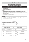
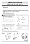
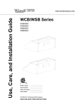
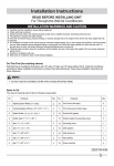
1
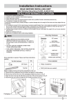
Installation Instructions READ BEFORE INSTALLING UNIT For SLO3 Air Conditoner (8,000~12,000 BTU) INSTALLATION WARNINGS AND CAUTION Carefully read the installation manual before beginning. Follow each step as shown. Observe all local, state, and national electrical codes and by qualified, licensed, authorized personnel only. Pay attention to danger and safety notices. To avoid risk of personal injury, property damage, or product damage due to the weight of this device and sharp edges that may be exposed: Air conditioners covered in this manual pose an excessive weight hazard. Two or more people are needed to move and install the unit. Wear protective gloves whenever lifting or carrying the unit. AVOID the sharp metal fins of front and rear coils. To prevent injury or strain, use proper lifting and carrying techniques when moving unit. Carefully inspect location where air conditioner will be installed. Be sure it will support the weight of the unit overan extended period of time. Handle air conditioner with care. Make sure air conditioner does not fall during installation. Tools and Parts: Gather the required tools and parts before starting installation. Read and follow the instructions provided with any tools listed here. TOOLS NEEDED Flat-blade and Phillips screwdrivers Tape measure Level 'ULOODQGƎƎ,ƎRUVPDOOHUGULOOELW Through-the-wall Installation: In addition to the tools listed above, the following tools are needed for through-the-wall installation. TOOLS NEEDED saw ;ƎZRRGVFUHZV caulk ƎFPRUWKLFNHUOXPEHU Parts Supplied: Check that all parts are included in parts package: Qty. Hardware Qty. Hardware ;Ǝpan - head Phillips screws 3 Top channel 1 ;Ǝround - head screws Window sash seal 1 ;Ǝpan - head Phillips screws Foam seal 1 window lock bracket 1 Safety Lock (for Vinyl-Clad window) 2 side curtains 2 weather seals Ǝ;Ǝ;Ǝ 2020213A1640 1 Installation Instructions NOTE: ,QVWDOODWLRQSDUWVDUHVXSSOLHGIRUGRXEOHKXQJZLQGRZVXSWRƎFPZLGH$VSHFLDO:LGH:LQGRZ.LWLV available from your dealer or service center. See “Accessories.” Do not use any screws other than those specified here. Location Requirements: IMPORTANT:Observe all governing codes and ordinances. Check the location where air conditioner will be installed. Proper installation is your responsibility. Make sure you have everything necessary for correct installation. Grounded electrical outlet within 4 ft (122 cm) of where the power cord exits the air conditioner. Free movement of air in room to be cooled. A large enough opening for the air conditioner. Adequate wall support for weight of air conditioner. Air conditioner weights between 70 and 85 Ibs (32 to 40 kgs). NOTE: Do not use an extension cord. Cabinet louvers must not be obstructed. Air must be able to pass freely through the cabinet louvers.(FIG.1) Window Installation: Window opening measurements (FIG.2) : ƎWRƎFPWRFPRSHQLQJZLGWK ƎFPPLQLPXPRSHQLQJKHLJKW FIG.1 FIG.2 A A. Cabinet louvers $ƎFPPLQLPXP %ƎFPPLQLPXP Remove packaging material: Remove and dispose of / recycle packaging materials. Remove tape and glue residue from surfaces before installing the air conditioner. Rub a small amount of liquid dish soap over the adhesive with your fingers. Wipe with warm water and dry. Do not use sharp instruments, rubbing alcohol, flammable fluids, or abrasive cleaners to remove tape or glue. These products can damage the surface of your air conditioner. Handle the air conditioner gently. 1. Remove the air conditioner from the carton and place it on cardboard. 2. Remove 1 shipping screw from each side of the cabinet (FIG.3A). 3. Remove front panel by removing 1 Phillips screw from each side of the front panel. Set screws aside and save (FIG.3B). 4. Rotate Front Panel up until top tabs are free. Pull panel straight out. Depress latch on electronics plug (on some models) to disconnect. Remove Front Panel from unit (see Fig. 4). 5. Pull on the handles to slide the air conditioner out of the cabinet. Place the air conditioner on cardboard (FIG.5). 2 Installation Instructions FIG.3A FIG.3B FIG.4 FIG.5 B C B A A. shipping screw electronics plug B. front panel screw C. handle NOTE: Handle the air conditioner gently. Be sure your air conditioner cabinet does not fall out of the opening during installation or removal. The place where the power cord exits the air conditoner should be no more than 4 ft (122 cm) from a grounded 3 prong outlet. Do not block the louvers on the front panel. Do not block the louvers on the outside of air conditioner. Do not lift, pull or remove any expanded polystyrene (foam) from inside of the air conditioner. It is not packing material A Attach Top Channel (FIG.6): B NOTE: FIG.6 O Attach the top channel and side curtains to the air conditioner cabinet before placing the cabinet in the window. 1. Locate provided bag of screws. 2. Place the top channel on top of the air conditioner cabinet, lining up the three holes in the top channel with the three holes on top of the air conditioner cabinet. 8VLQJWKUHH;ƎSDQKHDG3KLOOLSVWKUHDGFXWWLQJVFUHZVDWWDFKWKHWRS channel to the air conditioner cabinet. $;ƎSDQKHDG3KLOOLSV thread cutting screws B. Top channel Attach Side Curtains : 1. Locate provided bag of screws. ,QVHUWWKHULJKWKDQGFXUWDLQFRQQHFWRUWDELQWRWKHFXUWDLQKRXVLQJFKDQQHOVRQWKHDLUFRQGLWLRQHU),*$ ,QVHUWWKHWRSDQGWKHQWKHERWWRPRIWKHULJKWKDQGFXUWDLQKRXVLQJLQWKHWRSDQGERWWRPFXUWDLQFKDQQHOVRQWKH air conditioner (FIG.7B, FIG.7C). 4. Slide the curtain housing into the curtain guides as far as it could go. 5HSHDWWKHDERYHVWHSVIRUWKHOHIWKDQGFXUWDLQ FIG.7B Top view FIG.7A A A B FIG.7C Bottom view A B A. Side Curtain A. Curtain housing B. Curtain top channel on air conditioner A. Curtain housing B. Curtain bottom channel on air conditioner 3 Installation Instructions $WWDFKIRDPDGKHVLYHVHDO $WWDFKIRDPDGKHVLYHVHDODORQJWKHERWWRPRIWKHFXUWDLQERWWRPFKDQQHO),* FIG.8 FIG.9 $QJOHRIFDELQHW FIG.10 EUDFNHWVHFXUHO\VHDWHG on edge of inner sill. $ $Curtain housing %)RDPDGKHVLYHVHDO C FDELQHW %UDFNHW window inner sill % $ % window outer sill ,QVWDOO&DELQHWLQWR:LQGRZ $:LQGRZVDVK %(PSW\FDELQHW &:LQGRZFKDQQHO &HQWHUHPSW\FDELQHWLQZLQGRZ &KHFNWKDWORZHUUDLORIDLUFRQGLWLRQHUFDELQHWLVEHKLQGDQGDJDLQVWEDFNVLGHRIZLQGRZVLOO0DLQWDLQDILUPKROGRQ WKHDLUFRQGLWLRQHUFDELQHW),*/RZHUZLQGRZVDVKWRKROGWKHFDELQHWLQSODFH0HDVXUHWKHGLVWDQFHEHWZHHQWKH ULJKWVLGHRIWKHFDELQHWDQGWKHLQVLGHRIWKHZLQGRZFKDQQHO),*5HSHDWIRUWKHOHIWVLGH$GMXVWWKHFDELQHWXQWLO the distance on each side is the same. $WWDFKWKHFDELQHWWRZLQGRZ A: For wooden window: 8VHDƎGULOOELWWRGULOOWKUHHVWDUWHUKROHVƎGHHSWKURXJKWKHWKUHHKROHVLQWKHFDELQHWDQGLQWRWKHZLQGRZVLOO DQGGULOORQHVWDUWHUKROHƎGHHSWKURXJKWKHKROHLQWKHPLGGOHRIWRSUDLODQGLQWRWKHZLQGRZIUDPH),*$WWDFK FDELQHWWRZLQGRZZLWKWKUHH[ƎSDQKHDG3KLOOLSVVFUHZVDQGRQH;ƎURXQGKHDGVFUHZ),* B: For Vinyl-Clad window: 8VHDƎGULOOELWWRGULOORQHKROHWKURXJKWKHKROHLQWKHPLGGOHRIWRSUDLODQGLQWRWKHZLQGRZIUDPH$WWDFKFDELQHW WRZLQGRZZLWKRQH[ƎURXQGKHDG3KLOOLSVVFUHZ),*3ODFHWZRVDIHW\ORFNVLQWRWKHKROHVWKDWORFDWHG LQWKHERWWRPRIWKHFDELQHWDQGGULYHWZRORFNLQJVFUHZVWKURXJKWKHVDIHW\ORFNVLQWRWKHFDELQHWDVVKRZQ),* &KHFNWKDWDLUFRQGLWLRQHULVWLOWHGEDFNDERXWƎWRƎWLOWHGDERXWWRGRZQZDUGWRWKHRXWVLGHVHH ),*$IWHUSURSHULQVWDOODWLRQFRQGHQVDWHVKRXOGQRWGUDLQIURPWKHRYHUIORZGUDLQKROHGXULQJQRUPDOXVHFRUUHFW the slope otherwise. FIG.13 :LQGRZ6DVK FIG.12 FIG.11 $ % % DERXWƎƎ C $ $ $ $;ƎSDQKHDG3KLOOLSVVFUHZV %;ƎURXQGKHDGVFUHZ &:LQGRZFKDQQHO 6LGH/RXYHUV $;ƎSDQKHDG3KLOOLSVVFUHZV %6DIHW\/RFN 2QO\IRU9LQO\&ODG:LQGRZ :LQGRZ6LOO $WWDFK6LGH&XUWDLQVWR:LQGRZ)UDPH 1. Extend the side curtains out against the window frame $ ),*% $ ),*$ (FIG.11). 2. Drill holes and drive locking screws: A: For wooden windows: 8VHDƎGULOOELWWRGULOOVWDUWHUKROHVWKURXJKWKHKROHVLQ WKHVLGHFXUWDLQVLQWRWKHZLQGRZ'ULYHIRXU;ƎORFNLQJ % screws through the holes in the side curtains into the window % C VLOODQGZLQGRZIUDPH),*$),*% B: For Vinyl-Clad windows: $:LQGRZFKDQQHO 8VHDƎGULOOELWWRGULOOWZRKROHVWKURXJKWKHKROHVLQWKH $;ƎURXQGKHDG %OHIWKDQGFXUWDLQ VLGHFXUWDLQVLQWRWKHZLQGRZIUDPHDVVKRZQ),*$ screw &;ƎURXQGKHDG 'ULYHWZR;ƎORFNLQJVFUHZVWKURXJKWKHKROHVLQWKH %6ORWWHGKROHLQWKH screw VLGHFXUWDLQVLQWRWKHZLQGRZVDVK),*$ ERWWRPRIWKHFXUWDLQ 3. Trim the weather seal Ǝ;Ǝ;ƎZLWKDSURSHUOHQJWKSHHORIIWKHSURWHFWLYHEDFNLQJDQGSOXJDQ\JDSVLI QHHGHGDVVKRZQ),*% 4 Installation Instructions FIG.15 B C Complete Installation: 1. Insert window sash seal behind the top of the lower window sash and against the glass of the upper window (FIG.15). 2. Place the window-lock bracket on top of lower window and against upper window sash on right side of the window (FIG.15). 8VHDƎGULOOELWWRGULOOVWDUWHUKROHVWKURXJKWKHKROHVLQWKHEUDFNHWLQWR the window sash (FIG.15). $WWDFKWKHZLQGRZORFNEUDFNHWWRWKHZLQGRZVDVKZLWKWZR;Ǝ round-head screws to secure window in place (FIG.15). 5. Insert air conditioner into cabinet (FIG.16). 6. Reconnect electronics plug if present. Insert front tabs of front panel into top of cabinet and swing front into place (FIG.17A). 7. Attach bottom front of panel with front panel screws (FIG.17B). 8. Plug into a grounded 3 prong outlet. 9. Press RESET on the power supply cord. FIG.16 FIG.17A D A. Window lock bracket B. Upper window glass C. Window sash seal ';ƎURXQGKHDG screws FIG.17B electronics plug Through-the-Wall Cabinet Installation: Option 1—wood, metal or plastic molding: When using a wood, metal or plastic molding, the wood frame should line up with the inside wall as shown FIG.18. Option 2—Plastered wall with no molding: ,IWKHSODVWHUHGZDOOLVWREHIOXVKZLWKWKHFDELQHWDQGQRPROGLQJLVXVHGWKHZRRGIUDPHPXVWEHVHWƎPP into the inside wall FIG.19. FIG.18 FIG.19 FIG.20 AB C A B C C D D A B D A. Molding B. Inside wall C. Wood frame D. Louvers A. Plastered wall B. Inside wall C. Wood frame D. Louvers A $ƎFP C %ƎFP C. Wood thickness 'ƎFPPLQLPXPWR ƎFPPD[LPXP Install Wood Frame: 1. Construct the wood frame. See FIG.20 for dimensions. 2. Measure the outside width and height of frame to determine wall opening dimensions. The wall opening measurements should be : :LGWKƎFPSOXVWZLFHWKLFNQHVVRIZRRGXVHGWREXLOGIUDPH +HLJKWƎFPSOXVWZLFHWKLFNQHVVRIZRRGXVHGWREXLOGIUDPH 'HSWKƎFPPLQLPXPWRƎFPPD[LPXP 3. Cut the opening through the wall. Remove and save insulation. 4. Apply the wood preservative to the outside exposed surface. 5. Insert the frame in the wall opening. Square and level frame. 6. Attach frame securely to the wall. 5 Installation Instructions FIG.21 A NOTE: Dimension for depth depends on wall thickness and type of molding (FIG.21). Do not block louvers in air conditioner cabinet. 8VHƎFPRUWKLFNHUOXPEHUIRUZRRGIUDPH B C A. Outside width C. Depth B. Outside height Install Cabinet into Wood Frame: ,QVHUWFDELQHWLQWRWKHIUDPHGZDOORSHQLQJ7KHWRSRIWKHFDELQHWVKRXOGH[WHQGƎPPLQWRWKHURRP,I WKHUHLVWULPWKHFDELQHWVKRXOGH[WHQGƎPPSDVWWULP),* 2. Use a level to check that cabinet is level side to side (FIG.23). 3. Check that air conditioner cabinet is tilted to the outside so that water could run to the outside. The cabinet should slop at least half-a-bubble towards the rear. 4. Reuse the insulation to seal opening between cabinet and frame. 8VHH[LVWLQJKROHVLQVLGHVDQGWRSRIFDELQHWDQGVHYHQ;ƎZRRGVFUHZVQRWSURYLGHGWRDWWDFKFDELQHWWR frame. 6. Caulk all outside wall openings around cabinet. NOTE: Do not overtighten screws or the cabinet will distort and provide a poor air seal between cabinet and air conditioner. B A FIG.22 FIG.23 A $ƎPPH[WHQGLQJLQWRURRP B. Trim A. level Complete Installation: 1. Insert air conditioner into cabinet (FIG.24). 2. Reconnect electronics plug if present. Insert front tabs of front panel into top of cabinet and swing front into SODFH),*$ $WWDFKERWWRPIURQWRISDQHOZLWKIURQWSDQHOVFUHZV),*% 4. Plug into a grounded 3 prong outlet. 3UHVV5(6(7RQWKHSRZHUVXSSO\FRUG NOTE: Handle the air conditioner gently . For through-the-wall installations, if needed, install molding around the room side of cabinet. FIG.24 ),*$ electronics plug 6 ),*%