1
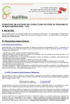
RT5
1 Heat/1 Cool
Manual Changeover
Battery or Hardwired
Non-Programmable Electronic Thermostat
• For use with Friedrich PTAC units ONLY
• Backlit Display
• Filter Check
• Status Indicator Light
• Relay Outputs
(minimum voltage drop in thermostat)
• Two-Speed Fan
Installation, Operation & Application Guide
Table of Contents
Parts Diagram............................................................................................................................................... 1
Specifications ............................................................................................................................................... 2
Important Safety Information ........................................................................................................................ 2
Package Contents/Tools Required ............................................................................................................... 2
To Remove Existing Thermostat................................................................................................................... 3
To Install Thermostat .................................................................................................................................... 3
Wiring Diagrams ........................................................................................................................................... 5
Configuration Mode ...................................................................................................................................... 6
Testing the Thermostat ................................................................................................................................. 9
Mode of Operation ...................................................................................................................................... 10
Troubleshooting ...........................................................................................................................................11
Parts Diagram
1
Specifications
Electrical rating: • 24 VAC (18-30 VAC)
• DC Power: 3.0 VDC (2 “AA” batteries included)
• 1 amp maximum per terminal
• 3 amp maximum total load
Temperature control range: 45°F to 90°F (7°C to 32°C) Accuracy: ± 1°F (± 0.5°C)
System configurations: 1-stage heat, 1-stage cool, heat pump, electric
Timing: Anti-short Cycle: 5 minutes
Backlight Operation: Battery for 5 seconds, hardwired for 10 seconds
Terminations: RC, RH, W, Y, B, O, GL, GH, C
Important Safety Information
warning!: Always turn off power at the main power supply before installing, cleaning, or removing
thermostat.
• This thermostat is for 24 VAC applications only; do not use on voltages over 30 VAC
• Do not short across terminals of system control to test operation; this will damage your thermostat and void your
warranty
• All wiring must conform to local and national electrical and building codes
• Do not use air conditioning when the outdoor temperature is below 50 degrees; this can damage your A/C system
and cause personal injuries
• Use this thermostat only as described in this manual
Package Contents/Tools Required
Package includes: RT5 thermostat on base, thermostat cover, wiring labels, screws and wall anchors, Installation,
Operation and Application Guide
Tools required for installation: Drill with 3/16" bit, hammer, screwdriver
2
To Remove Existing Thermostat
ELECTRICAL SHOCK HAZARD – Turn off power at the main service panel by removing the
fuse or switching the appropriate circuit breaker to the OFF position before removing the
existing thermostat.
1. Turn off power to the heating and cooling system by removing the fuse or switching the appropriate circuit breaker
off.
2. Remove cover of old thermostat. This should expose the wires.
3. Label the existing wires with the enclosed wire labels before removing wires.
4. After labeling wires, remove wires from wire terminals.
5. Remove existing thermostat base from wall.
6. Refer to the following section for instructions on how to install this thermostat.
To Install Thermostat
ELECTRICAL SHOCK HAZARD – Turn off power at the main service panel by removing the
fuse or switching the appropriate circuit breaker to the OFF position before removing the
existing thermostat.
IMPORTANT: Thermostat installation must conform to local and national building and electrical codes and
ordinances.
Note: Mount the thermostat about five feet above the floor. Do not mount the thermostat on an outside wall,
in direct sunlight, behind a door, or in an area affected by a vent or duct.
1. Turn off power to the heating and cooling system by removing the fuse or switching the appropriate circuit breaker
off.
3
To Install Thermostat (continued)
2.
To remove cover, insert and twist a coin or screwdriver in the slots on the sides of the thermostat.
3.
Put thermostat base against the wall where you plan to mount it (Be sure wires will feed through the wire opening
in the base of the thermostat).
4.
Mark the placement of the mounting holes.
5.
Set thermostat base and cover away from working area.
6.
Using a 3/16” drill bit, drill holes in the places you have marked for mounting.
7.
Use a hammer to tap supplied anchors in mounting holes.
8.
Align thermostat base with mounting holes and feed the control wires through wire opening.
9.
Use supplied screws to mount thermostat base to wall.
10. Insert stripped, labeled wires in matching wire terminals. See “Wiring Diagram” section of this manual (Page 5).
caution!: Be sure exposed portion of wires does not touch other wires.
11. Tighten screws on terminal block. Gently tug wire to be sure of proper connection. Double check that each wire is
connected to the proper terminal.
12. Seal hole for wires behind thermostat with non-flammable insulation or putty.
13. Set Elec/Gas switch to
Electric = heat pump, electric strip heat
14. Replace cover on thermostat by snapping it in place.
15. Turn on power to the system at the main service panel.
16. Test thermostat operation as described in “Testing the Thermostat” (Page 9).
4
HARDWIRED
PRE-INSTALLED JUMPER
C
F
R
I
E
D
R
I
C
H
C
RH
P
T
A
C
R
RC
W
W
Y
Y
B
B
O
GL
GL
GH
GH
T
H
E
R
M
O
S
T
A
T
5
Configuration Mode
The configuration mode is used to set the RT5 to match your heating/cooling system. The RT5 functions with Friedrich PTAC models.
Ensure that the thermostat is configured for air conditioning with ELECTRIC HEAT ONLY.
To configure the RT5, perform the following steps:
1. Remove the cover of the thermostat by gently pulling on one of the corners.
2. Simultaneously hold the SW5 and SW6 buttons in for 5 seconds while the RT5 is in OFF mode.
3. Press the
or
button to change settings within each screen.
4. Press the SW6 button to advance to the next screen.
Note: The SW5 button will return you to the previous screen.
5. To exit configuration mode, slide the Mode switch to Heat or Cool.
Configuration Mode Settings
The nine (9) setup screens for Configuration Mode are as follows:
1. Heat pump and Non Heat Pump – Press the
or
button to configure as heat pump, or
non-heat pump system. For heat pumps, there will be an anti-short cycle delay for heating
and cooling
• 0 = Non-heat pump system
Press the SW6 button to advance to the next screen.
2. Temperature Scale (F or C) – Choose Fahrenheit or Celsius.
or
button to select.
Press the
Press the SW6 button to advance to the next screen.
SET
ROOM
DIFF
FILTER
SET
ROOM
DIFF
FILTER
6
REMOTE
REMOTE
Configuration Mode Settings (continued)
3. Temperature Differential (1°F to 3°F) (0.5°C to 1.5°C) – Set the number of degrees between
your “setpoint” temperature and your “turn on” temperature.
or
button to set differential value.
Press the
Press the SW6 button to advance to the next screen.
4. Minimum Cool Setpoint (45°F to 75°F) (7°C to 24.0°C)
Adjust to control the minimum Cool set temperature allowed.
or
button to select.
Press the
Press the SW6 button to advance to the next screen.
SET
ROOM
REMOTE
DIFF
FILTER
SET
ROOM
REMOTE
DIFF
FILTER
SET
ROOM
REMOTE
DIFF
FILTER
5. Maximum Heat Setpoint (55°F to 90°F) (13°C to 32°C)
Adjust to control the maximum Heat set temperature allowed.
or
button to select.
Press the
Press the SW6 button to advance to the next screen.
SET
ROOM
REMOTE
DIFF
FILTER
SET
ROOM
REMOTE
DIFF
FILTER
7
6. Room temperature offset (+9°F to -9°F) (+4.5°C to -4.5°C)
Adjust to calibrate displayed room temperature to match actual room temperature.
Note: When not set to 0, ROOM will display
or
button to select.
Press the
Press the SW6 button to advance to the next screen.
SET
ROOM
7. Maximum compressor cycles allowed per hour (-, 2-6)
- = as many as needed, 2-6 = maximum cycles/hour
Press the
or
button to select.
Press the SW6 button to advance to the next screen.
SET
ROOM
8. Filter Check time (300-800, – – –)
Set Fan Run Time (in hours) when Check Filter is displayed or set to – – – to disable.
Press the
or
button to select.
Note: To reset filter counter to zero and clear filter warning, press
and
buttons simultaneously for 5 seconds.
the
Press the SW6 button to advance to the next screen.
9. Status Indicator Light (Lt 0 or 1)
0 = Status indicator never on
1 = Status indicator on with first stage
Press the
or
button to select.
Note: Red light indicates heating cycle and green light indicates cooling cycle
Slide the Mode switch to Heat or Cool to exit configuration.
8
REMOTE
DIFF
FILTER
REMOTE
DIFF
FILTER
REMOTE
SET
ROOM
DIFF
FILTER
(500 Hours)
SET
ROOM
DIFF
FILTER
REMOTE
Testing the Thermostat
Once the thermostat is installed, it should be thoroughly tested.
caution!: Do not energize the air conditioning system when the outdoor temperature is below 50
degrees. It can result in equipment damage or personal injury.
Cool Test
1.
2.
3.
4.
Slide Mode switch to Cool mode.
Adjust set temperature so it is 5 degrees below room temperature.
Air conditioning should come on within a few seconds. Status indicator may come on.
Adjust the set temperature 2 degrees above the room temperature and the A/C should turn off.
There may be a fan delay on your system.
Note: There is a five minute time delay to protect the compressor after it turns off. To
temporarily bypass the five minute delay, slide the Mode switch to OFF for 2 seconds
and then back to Cool.
Cool Off Heat
Heat Test
1.
2.
3.
4.
Slide Mode switch to Heat mode.
Adjust the set temperature so it is 5 degrees above the room temperature.
Heat should come on within a few seconds. Status indicator may come on.
Adjust the set temperature so it is 2 degrees below the room
temperature and the heat should turn off. There may be a fan delay on your system.
Note: For heat pumps, there is a five minute time delay to protect the compressor after
it turns off. To temporarily bypass the five minute delay, slide the Mode switch to
OFF for 2 seconds and then back to Heat.
Cool Off Heat
(Testing the thermostat continued on Page 10)
9
(Testing the thermostat continued from Page 9)
Fan Test
1. Slide Fan switch to On position.
2. Indoor fan turns on.
3. Slide Fan switch to Auto position.
4. Indoor fan turns off.
Auto
On
Auto
On
Mode of Operation
The RT5 is a single-stage heat, single-stage cool thermostat.
The RT5 can use 24 VAC or batteries as a power supply. The RT5 can be hardwired and have no batteries installed in the
battery compartment. It can also run on battery power only. When batteries are installed and the thermostat is hardwired,
the batteries will run the thermostat during a power outage.
When operating on battery power, the backlight will be on for 5 second intervals. When hardwired, the backlight will be on
for 10 second intervals.
The thermostat activates a heating appliance when the room temperature is below the heat set temperature (by the
differential temperature). It will turn off when the room temperature is one degree above the heat set temperature. With
heat pumps, the thermostat will not let the compressor come on for five minutes after it turns off. This protects your
compressor.
When the room temperature is greater than the cool set temperature (by the differential temperature), the cooling device
is activated. It will turn off when the room temperature is one degree below the cool set temperature. The thermostat will
not let the compressor come on for five minutes after it turns off. This protects your compressor.
The RT5 has the following operating modes: OFF, Heat and Cool. In OFF mode, the thermostat will not turn on heating or
cooling devices. In the Heat mode, the thermostat controls the heating system. In the Cool mode, the thermostat controls
the cooling system. The indoor fan can be turned on in all operating modes using the Fan switch.
10
Troubleshooting
Symptom
Remedy
No display
For Hardwired Installation
Check for 24 VAC at thermostat; display is blank when 24 VAC is not present
For Battery Installation
Display is blank when batteries are drained or installed incorrectly
System fan does not come on
properly
Verify wiring is correct
Thermostat turns on and off too
frequently
Adjust temperature differential (see “Temperature Differential,” Step 3, Page 6)
Check position of gas/electric switch
Fan runs continuously
Check fan On/Auto switch, ON position runs indoor fan continuously
Fan operates at wrong speed
Slide High/Low fan switch to correct position
Room temperature is not correct
Verify wall hole is plugged with putty or insulation; calibrate thermostat (see “Configuration,”
Step 6, Page 8)
ROOM displays
Room temperature offset is not zero (see “Configuration,” Step 6, Page 8)
Status indicator
Green light – Cooling operation
Red light – Heating operating
Status indicator option ON (see “Configuration,” Step 9, Page 8)
filter displays
Fan run time has exceeded filter check time set in configuration (see “Configuration,” Step 8,
Page 8)
To reset counter to zero and clear
for 5 seconds
filter warning, press the
and
button simultaneously
11
Friedrich Air Conditioning Co.
Post Office Box 1540 • San Antonio, Texas 78295-1540
4200 N. Pan Am Expressway • San Antonio, Texas 78218-5212
(210) 357-4400 • FAX (210) 357-4480
www.friedrich.com