1
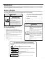
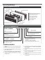
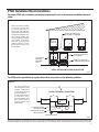
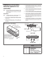
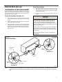
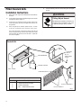
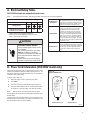
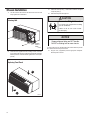
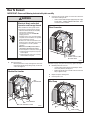
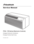
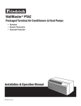
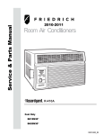
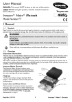
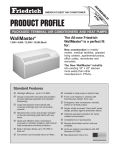
Installation and Operation Manual
PTAC
Packaged Terminal Air
Conditioners & Heat Pumps
920-087-09 (10/10)
Table of Contents
Congratulations......................................................................................................................................................................................................................... 3
General Instructions.................................................................................................................................................................................................................. 3
General Specifications.............................................................................................................................................................................................................. 4
Installation Checklist................................................................................................................................................................................................................. 4
PTAC Installation Recommendations....................................................................................................................................................................................... 5
Wall Sleeve Installation Instructions (PDXWS)......................................................................................................................................................................... 6
Alternate Wall Installations........................................................................................................................................................................................................ 7
One-Piece Deep Wall Sleeve Installation (PDXWSEXT)......................................................................................................................................................... 9
PXDR10 Drain Kit Installation Instructions (optional for new construction)............................................................................................................................ 10
External Drain (for new construction or unit replacement)..................................................................................................................................................... 11
PXGA Standard Grille Installation Instructions....................................................................................................................................................................... 12
Electrical Wiring for 265 Volt Models...................................................................................................................................................................................... 14
Chassis Install Preparation..................................................................................................................................................................................................... 16
Chassis Installation ................................................................................................................................................................................................................ 18
How To Connect...................................................................................................................................................................................................................... 19
Friedrich PTAC Digital Control and Unit Features.................................................................................................................................................................. 20
System Configuration.............................................................................................................................................................................................................. 22
Digital Control User Input Configuration................................................................................................................................................................................. 23
Digital Control Operation........................................................................................................................................................................................................ 24
Remote Control Thermostat Installation................................................................................................................................................................................. 25
Remote Thermostat and Low Voltage Control Connections.................................................................................................................................................. 25
Final Inspection & Start-up Checklist..................................................................................................................................................................................... 27
Routine Maintenance.............................................................................................................................................................................................................. 27
Basic Troubleshooting............................................................................................................................................................................................................. 28
Service & Assistance.............................................................................................................................................................................................................. 29
Accessories............................................................................................................................................................................................................................. 30
NOTE:
2
All PTAC 7000, 9000, 12000 units come with a standard 3 kW power cord. All PTAC 15000 units come with a standard 5 kW power cord.
For units using our optional heating cords (0kW, 2kW, 3kW, and 5kW) please refer to page 14 for the proper accessory part numbers and
power cord installation instructions.
Congratulations
Thank you for your decision to purchase Friedrich. Your new Friedrich has been carefully engineered and manufactured to give you many years of dependable,
efficient operation, maintaining a comfortable temperature and humidity level. Many extra features have been built into your unit to assure quiet operation,
the greatest circulation of cool, dry air, and the most economic operation.
General Instructions
This Installation and Operation Manual has been designed to insure maximum satisfaction in the performance of your unit. For years of trouble-free service,
please follow the installation instructions closely. We cannot overemphasize the importance of proper installation.
and the controls are properly set, the unit may need service and
you should call your Friedrich service provider to check the unit.
WARNING
Refrigeration system
under high pressure
Do not puncture, heat, expose to flame or
incinerate.
Only certified refrigeration technicians should
service this equipment.
R410A systems operate at higher pressures
than R22 equipment. Appropriate safe
service and handling practices must be used.
Only use gauge sets designed for use with
R410A. Do not use standard R22 gauge sets.
Here are some suggestions to help you use your
new Friedrich most efficiently:
1.
Carefully read and follow the installation instructions.
2. Make sure the unit is the right capacity for the area being cooled.
An undersized unit makes the unit work too hard, using more
electricity than needed and increases wear. An oversized unit
will cycle on and off too rapidly, and therefore cannot control
humidity as well.
3. Clean the filter frequently (See Routine Maintenance, Page 27).
4.
Do not block the air flow to and from the unit.
5. A dirty filter or improperly set controls can affect the cooling
ability of the unit.
6. If cooling is weak and you have verified that the filter is clean
7.
Keep blinds, shades and drapes closed on the sunny side of the
room being cooled to reduce radiant heat.
8. Proper insulation helps your unit maintain the desired inside
temperature.
9. Whenever possible, shade south and west facing windows.
10. Keep window coverings away from the unit to provide free air flow.
WARNING
Read Installation Operation
Manual
Please read this manual thoroughly prior to
equipment installation or operation.
It is the installer’s responsibility to properly
apply and install the equipment. Installation
must be in conformance with the NFPA 70
-2008 National Electric Code or current edition,
International Mechanic Code 2009 or current
edition and any other applicable local or
national codes.
Failure to do so can result in property damage,
personal injury or death.
Your safety and the safety of others are very important.
We have provided many important safety messages in this manual and on your appliance. Always read and obey all
safety messages.
This is a safety Alert symbol.
This symbol alerts you to potential hazards that can kill or hurt you and others.
All safety messages will follow the safety alert symbol with the word “WARNING”
or “CAUTION”. These words mean:
A NIN
WARNING
Indicates a hazard which, if not avoided, can result in severe personal injury or
death and damage to product or other property.
CAUTION
Indicates a hazard which, if not avoided, can result in personal injury and
damage to product or other property.
All safety messages will tell you what the potential hazard is, tell you how to reduce the chance of injury, and tell you
what will happen if the instructions are not followed.
NOTICE
Indicates property damage can occur if instructions are not followed.
3
General Specifications
Typical Unit Components and Dimensions
WALL SLEEVE
OUTDOOR GRILLE
DISCHARGE
GRILLE
FILTERS
PDXWS Wall Sleeve Dimensions:
16" H x 42" W x 13-¾" D
Front Cover Dimensions:
16" H x 42" W x 7-¾" D
Cut-Out Dimensions:
16-¼" x 42-¼"
CHASSIS
RETURN AIR GRILLE
FRONT COVER
MODEL NUMBER
Series
PD = Friedrich Digital PTAC
System
X = Accessory
E = Cooling with or without electric heat
H = Heat Pump with Auxiliary Heat
Engineering Digit
Design Series
Note: All PTAC models with a C design series or
later come standard with Diamonblue seacoast
protection and digital controls.
Chassis
S = Standard
Nominal Capacity
07 = 7,000 Btuh
09 = 9,000 Btuh
12 = 12,000 Btuh
15 = 15,000 Btuh
Voltage
K = 230/208V - 1 Ph. - 60 Hz.
R = 265V - 1 Ph. - 60 Hz.
Nominal Heater Size (230V or 265V)
0 = No Heater*
2 = 2.0 KW 3 = 3.0 KW
5 = 5.0 KW**
* No Heater only available on 230V PDE models
** 5.0 kw only available on 9000, 12000 and 15000 BTU models
Installation Checklist
q Inspect all components and accessories for damage before and after
installation.
q Remove the cardboard wall sleeve support and grill weatherboard.
q Check for proper wall sleeve installation in accordance with the wall
sleeve installation instructions.
q Check for a subbase kit or other means of structural support which
is required for ALL installations projecting more than 8" into room.
q Install the recommended Condensate Drain Kits for complete
condensate removal.
4
q Ensure that the chassis is installed in a 16" high x 42” wide wall sleeve
that is no deeper than 13 ¾". A baffle kit is required if the sleeve
exceeds that depth.
q Ensure that chassis and chassis front cover are installed and secured
properly.
q Ensure that drapes, bed, bedspread, furniture, etc. DO NOT block
either return or discharge air grilles.
q Inspect the condenser air inlet and outlet for any obstructions
(shrubbery, etc.)
q Ensure that 'reset' button is pressed on LCD device (only on cord
connected models).
PTAC Installation Recommendations
For proper PTAC unit performance and maximum operating life refer to the minimum installation clearances
below:
Figure 1
PTAC units should be installed
no closer than 12" apart when
two units are side by side. If
three or more PTAC units are to
operate next to one another allow
a minimum of 36" between units.
Also, a vertical clearance of 60"
should be maintained between
units installed. In the interior
of the room the unit should be
located a minimum of 1/4" from
the floor and a minimum of 36"
from the ceiling.
THREE OR MORE PTACs
ADJACENT 36" MINIMUM
TYPICAL
WINDOW
36"
TWO ADJACENT PTACs
12" MINIMUM
60"
60" VERTICAL
MIMUMUM
BETWEEN
PTACs
GROUND FLOOR PTACs
6" MINIMUM FROM GRADE
6"
12"
VIEW: OUTSIDE BUILDING ELEVATION
FRP001
For PTACs on the ground floor or anytime obstructions are present, use the following guidelines:
Figure 2
•
•
For minor obstructions
such as lamp poles or small
shrubbery a clearance of
12" from the outdoor louver
should be maintained.
For major obstructions such
as a solid fence, wall or
other heat rejecting device
like a condensing unit, a
minimum distance of 36"
should be kept.
TYPICAL BUILDING ( PLAN VIEW )
36"
36"
PTAC
PTAC
PTAC
12"
12" MINIMUM, MINOR
OBSTRUCTIONS
POLE
36" MIMUMUM, MAJOR
OBSTRUCTIONS
36"
SHRUB
FENCE OR WALL
CONDENSING UNIT
FRP002
The above suggestions are for reference only and do not represent all possible installations. Please contact Friedrich for information regarding affects of other
installation arrangements. By following these simple recommendations you can be confident that your Friedrich PTAC will provide years of worry free operation.
5
Wall Sleeve Installation Instructions (PDXWS)
NOTE:
Insure that the unit is only installed in a wall structurally adequate to support the unit including the sleeve, chassis and accessories. If the sleeve
projects more than 8" into the room, a subbase or other means of support MUST be used. Please read these instructions completely before
attempting installation.
WARNING
NOTICE
Falling Object Hazard
DO NOT allow any pitch toward the inside.
Not following Installation Instructions for
mounting your air conditioner can result
in property damage, injury, or death.
Flashing on all 4 sides of the opening is recommended.
Potential property damage can occur if instructions are
not followed.
For Deep Wall Installation (Greater than 13 1/4")
See Page 9
The following instructions apply ONLY to walls less than 13 ¼" in depth.
3. From inside the building, position the wall sleeve in the opening and
push it into the wall until it protrudes at least ¼” on the outside. Do
not allow sleeve to be pulled. (See Figure 11, Page 10).
1. The PXDR10 Drain Kit (optional for new construction) see page 10
if applicable, must be installed before the wall sleeve is installed
into the wall.
4. Position the wall sleeve with a slight tilt towards the outside to
facilitate condensate drainage. It should be level side-to-side and
the front should be ¼ bubble higher than the back.
2. The External Drain (for new construction or unit replacement) see
page 11, if applicable, must be installed before the wall sleeve is
installed into the wall.
Figure 3
Typical Wall Sleeve Installation
ELECTRICAL
RECEPTACLE
LINTEL TO SUPPORT
MASONRY WALLS
42-¼"
MIN.
16-¼"
20"
MAX.
60"
MAX.
SMOOTH SIDE OF SCREW
CLIP FACING INTO ROOM
13-¾"
INSULATION
ELECTRICAL
RECEPTACLE
WALL OPENING
WALL SLEEVE
INSULATION
NOTE: All 230/208V units are manufactured with a 60” power cord and all 265V units with a 18 ” power cord.
FRP008
6
Alternate Wall Installations
Figure 6
Figure 4
Curtain Wall
Panel Wall
WALL OR
WINDOW
1/4" MIN
PROJECTION
CASE FLANGE
(BY OTHERS)
OPTIONAL SUBBASE
OPTIONAL SUBBASE
LEVELING SCREW
LEVELING SCREW
FRP003
Figure 5
Figure 7
Frame and Brick Veneer
Block and Brick Veneer
1/4" MIN
PROJECTION
1/4" MIN
PROJECTION
CONCRETE LINTEL
WOOD FRAME
STEEL
LINTEL
STEEL
LINTEL
13-3/4" MIN.
WITHOUT SUBBASE
11" MIN.
WITH SUBBASE
OPTIONAL SUBBASE
RECEPTACLE
FINISHED FLOOR
LEVELING SCREW
FRP005
NOTE:
FRP004
POWER SUPPLY CONDUIT
(SUPPLIED BY INSTALLER)
FRP006
Follow all wall system manufacturer installation instructions. For sunrooms and modular buildings, adhere to their installation instructions for
supporting and sealing sleeve to their frames. All wall and window/wall installations must provide for proper drainage. In applications where the
drain holes on the PTAC wall sleeve are not exposed beyond the wall an internal drain system is recommended. It is the installer's responsibility
to ensure there is adequate drainage for the PTAC unit.
7
Figure 8
Wall Sleeve Attachment
ALTERNATE
FASTENING METHODS
(Field Supplied)
WALL
SLEEVE
NOTE: The Wall Sleeve must be
horizontally level (side-to-side)
and pitched 1/4 bubble to the
WOOD SCREW
outside when installed in an
opening.
TOGGLE BOLT
The mounting hole location
EXPANSION
should be approximately 2-4”
ANCHOR BOLT
from the top and bottom of the
sleeve.
MOUNTING
HOLES
PLASTIC ANCHORS
SCREWS
FRP007
Figure 9
Dimensions
A
¼" MIN.
Dimension*
C
13-¾"
B
WALL
A
B
C
Allow
for wall
finishing
Allow
for floor
finishing
Allow
for proper
drainage
Max. (Front-to-Back)
(Minimum)
Min.
No Accessories
¼"
¼"
---
---
With Subbase
1-¾"
3-½"
5"
---
With Lateral Duct
¾"
¼"
---
---
Wall Sleeve Tilt
---
---
---
¼"
* If more than one accessory is to be used, use the maximum
dimension. If the wall thickness is more than 13-¾" - (A+ ¼"),
a sleeve extension must be used.
FRP009
8
5. Drill two 3/16" holes through each side of the sleeve approximately
4" from top and 4" from bottom of sleeve. Screw four #10 x 1"
screws (included) or appropriate fasteners for your installation,
through the holes in the sides of the wall sleeve.
6. Apply sealant around the wall sleeve where it projects through the
inside and outside wall surfaces. Apply the sealant to the screw
heads or the tops of the fasteners used in Step #5.
Figure 10
7.
If the chassis and exterior grille are to be installed later, leave the
weatherboard and center support in place, otherwise remove and
dispose of them. (See Figure 13, Page 12).
8. Provide a support lintel if the wall sleeve is installed in a concrete
or masonry wall (See Figure 10, Page 9).
MAIN STUDS
Lintel Installation
JACK STUDS
LINTEL
JACK STUDS
MOUNTING
SCREW HOLES
MAIN STUDS
NO HOLES IN BOTTOM OF WALL
SLEEVE UNLESS DRAIN KIT IS USED
NOTE: Construct wall opening to comply with all applicable building codes.
FRP010
One-Piece Deep Wall Sleeve
Installation (PDXWSEXT)
If the wall is thicker than 13 1/4” a deep wall sleeve or wall sleeve extension
MUST be used. The deep wall sleeve may be special ordered through
your Sales Representative.
9
PXDR10 Drain Kit Installation
Instructions (optional for new
construction)
NOTE:
Determine whether drain will be located within the wall, on the
indoor side, or will drain to the exterior of the building. Follow
appropriate instructions below depending on your particular
type of installation.
Internal Drain
NOTE:
If installing an internal drain, you MUST install a drain kit on
the wall sleeve before the wall sleeve is installed.
1. Refer to Figure 11 and locate the drain within the “Preferred”
area of best drainage. Maintain at least a ½” clearance from the
embossed area.
2. Using the mounting plate with the ½” hole as a template, mark
and drill two, 3/16” mounting holes and a ½” drain hole in the
sleeve bottom.
3. Remove the backing from the gasket and mount it on the flat side
of the mounting plate. (See Figure 12, Page 11). Insert the drain
tube through the hole in the gasket and mounting plate so the tube
flange will be against the wall sleeve.
4. Position the assembly beneath the drilled holes and secure it with
#10-24 x ½" machine screws and lock nuts provided. Seal the tops
of the screws with silicone caulking.
5. Use ½" I.D. copper tube, PVC pipe, or vinyl hose (obtained locally)
to connect the internal drain tube to the drain system in the building.
6. Referring to Figure 12, Detail A, Page 11, locate and assemble the
(2) two cover plates and gaskets over the drain holes at the rear
of the wall sleeve. Attach them with the #10 sheet metal screws
provided. Make certain that the four overflow slots at the rear of
the wall sleeve are not blocked (See drawing of the back of the
sleeve Figure 12, Page 11).
7.
If a deep wall extension (PDXWSEXT) is used, after installing the
field supplied flashing, caulk as required. Be sure to caulk around
the flashing and the wall sleeve where the hole was drilled for the
drain tube.
SCREW
Figure 11
Drain Kit Location and Installation
WALL SLEEVE
OPTIONAL AREA
GASKET
PREFERRED AREANO FOAM INSULATION
MOUNTING
PLATE
DRAIN TUBE
NUT
SIDE VIEW
IF THE DRAIN MUST BE
LOCATED IN THE OPTIONAL
AREA, THE FOAM INSULATION
MUST BE CUT AWAY AND
REMOVED TO ALLOW ACCESS
TO THE DRAIN.
3"
FRONT VIEW
FRP011
PXDR10
QUANTITY
2
1
1
3
4
2
2
10
DESCRIPTION
COVER PLATES
MOUNTING PLATE
DRAIN TUBE
MOUNTING PLATE GASKET
#10 X ½” SHEET METAL SCREWS
#10-24 X ½ ” MACH. SCREWS
#10-24 X ½" LOCKNUTS
External Drain (for new
construction or unit replacement)
When using an external drain system, the condensate is removed through
either of two drain holes on the back of the wall sleeve. Select the drain
hole which best meets your drainage situation and install the drain kit.
Seal off the other with a cover plate.
Cover Plate Installation
4. Mount the foam gasket to the cover plate. Using two #10 x ½" sheet
metal screws (provided), attach the cover plate to the remaining
drain hole. Make certain the large flange on the plate is positioned
at the bottom of the sleeve.
5. Discard the additional cover plate, gasket, machine screws, and
locknuts.
Drain Tube Installation (See Figure 12)
1. Peel the backing tape off the gaskets and apply the sticky side
to one cover plate and one mounting plate as shown in Details
A and B.
2. Place the drain tube through the gasket and the mounting plate
with the flange toward the wall sleeve.
3. Attach the drain tube assembly to one of the two drain holes at the
rear of the wall sleeve. The large flange on the mounting plate is
positioned at the bottom of the sleeve facing toward the sleeve,
Detail B. When the drain tube is positioned at the desired angle,
tighten the screws.
NOTICE
If the wall sleeve has not been installed, the drain tube
must be rotated to a horizontal position until after the
sleeve is installed. Tighten the mounting plate screws
when the tube is in the proper position. Make certain that
the four overflow slots at the rear of the wall sleeve are not
blocked (See Figure 12).
When sealing the sleeve on the outside of the building, be
careful NOT to let the sealant block the two condensate
drain holes or the four overflow slots at the bottom flange
of the sleeve.
Potential property damage can occur if instructions are
not followed.
Figure 12
COVER
PLATE
Drain Kit Installation
MOUNTING
PLATE
FOAM
GASKET
DETAIL A
NUT
OVERFLOW
SLOTS
SCREWS
FOAM
GASKET
½” O.D. TUBE
DETAIL B
NOTE:
FRP012
The large flange on the mounting plate is positioned at the bottom of the sleeve facing toward the sleeve. The drain tube must be rotated to a
horizontal position to allow for the wall sleeve to be installed into the wall. Once the wall sleeve is installed, return the drain tube to a downward
angle.
11
PXGA Standard Grille
Installation Instructions
5. Insert the remaining screws into the remaining holes and tighten
securely.
WARNING
1. Remove the center support and weatherboard if still installed in
the sleeve.
2. Insert six plastic grommets into the grille openings from the outside
of the grille as shown in Figure 13.
Falling Object Hazard
3. Insert two #8 x ⅜" sheet metal screws (provided) in the top two
outside edge plastic grommets, and tighten them half way into
the grommets.
Not following Installation Instructions for
mounting your air conditioner can result
in property damage, injury, or death.
4. Grasp the grille by the attached plastic handles. Position
it with the condensate drain knockouts facing down.
From inside the building, maneuver the grille through the wall
sleeve and pull toward you until the screw heads are inserted
into the keyhole slots at the top of the wall sleeve. Tighten the
two screws completely.
Figure 13
Standard Grille
WALL
SLEEVE
STANDARD
GRILLE
#8 x 3/8”
SHEET METAL
SCREW
WEATHERBOARD
CENTER SUPPORT
WALL SLEEVE
STANDARD GRILLE
PXGA Standard Grille
Quantity
1
6
6
Description
Stamped Aluminum Grille
Plastic Grommets
#8 x " Sheet Metal Screws
PLASTIC GROMMETS
PLASTIC HANDLES
FRP013
12
A. Electrical Rating Tables
All 230/208 volt units are equipped with power cords.
NOTE:
Table 1
Use Copper Conductors ONLY. Wire sizes are per NEC, check local codes for overseas applications.
250V Receptacles and Fuse Types
AMPS
15
20*
30
FUSE/CIRCUIT
BREAKER
Use ONLY type and size fuse or HACR circuit breaker indicated on unit’s rating plate.
Proper current protection to the unit is the
responsibility of the owner. NOTE: A time
delay fuse is provided with 265V units.
GROUNDING
Unit MUST be grounded from branch circuit
through service cord to unit, or through
separate ground wire provided on permanently connected units. Be sure that
branch circuit or general purpose outlet is
grounded. The field supplied outlet must
match plug on service cord and be within
reach of service cord. Refer to Table 1 for
proper receptacle and fuse type. Do NOT
alter the service cord or plug. Do NOT use
an extension cord.
RECEPTACLE
The field supplied outlet must match plug on
service cord and be within reach of service
cord. Refer to Table 1 for proper receptacle
and fuse type. Do NOT alter the service
cord or plug. Do NOT use an extension
cord.
RECEPTACLE
TIME-DELAY TYPE FUSE
(or HACR circuit breaker)
15
20
30
HACR – Heating, Air Conditioning, Refrigeration
* May be used for 15 Amp applications if fused for 15 Amp
NOTE: 265 volt units are hard wired.
WARNING
Electrical Shock Hazard
Turn off electrical power before service
or installation.
ALL electrical connections and wiring
MUST be installed by a qualified
electrician and conform to the National
Code and all local codes which have
jurisdiction.
Failure to do so can result in property
damage, personal injury and/or death.
B. Power Cord Information (230/208V models only)
All Friedrich 230/208V PTAC units are shipped from the factory with a
Leakage Current Detection Interrupter (LCDI) equipped power cord. The
LCDI device meets the UL and NEC requirements for cord connected air
conditioners effective August 2004.
To test your power supply cord:
1. Plug power supply cord into a grounded 3 prong outlet.
2. Press RESET.
3. Press TEST ( listen for click; Reset button trips and pops out).
4. Press and release RESET (listen for click; Reset button latches
and remains in). The power supply cord is ready for operation.
NOTE:
The LCDI device is not intended to be used as a switch.
Figure 14
Typical LCDI Devices
RESET
TEST
TEST
RESET
WARNING
TEST BEFORE EACH USE
1. PRESS RESET BUTTON
2. PLUG LCDI INTO POWER
RECEPTACLE
3. PRESS TEST BUTTON,
RESET BUTTON SHOULD
POP UP
4. PRESS TEST BUTTON,
FOR USE
DO NOT USE IF ABOVE TEST
FAILS
WHEN GREEN LIGHT IS ON
IT IS WORKING PROPERLY
WARNING
TEST BEFORE EACH USE
1. PRESS RESET BUTTON
2. PLUG LCDI INTO POWER
RECEPTACLE
3. PRESS TEST BUTTON,
RESET BUTTON SHOULD
POP UP
4. PRESS TEST BUTTON,
FOR USE
DO NOT USE IF ABOVE TEST
FAILS
WHEN GREEN LIGHT IS ON
IT IS WORKING PROPERLY
Once plugged in the unit will operate normally without the need to reset
the LCDI device.
If the LCDI device fails to trip when tested or if the power supply cord is
damaged it must be replaced with a new supply cord obtained from the
product manufacturer, and must not be repaired.
15/20A LCDI Device
30A LCDI Device
FRP014
13
TABLE 2
Model
Heater kW
Power Cord Kit
Voltage
Amperage
Receptacle
PDE07K
0.0
PXPC23000
230/208
15
NEMA 6-15r
PDE/PDH07K
2.0
PXPC23015
230/208
15
NEMA 6-15r
3.0
STD
230/208
20
NEMA 6-20r
PDE09K
0.0
PXPC23000
230/208
15
NEMA 6-15r
PDE/PDH09K
2.0
PXPC23015
230/208
15
NEMA 6-15r
3.0
STD
230/208
20
NEMA 6-20r
5.0
PXPC23030
230/208
30
NEMA 6-30r
PDE12K
0.0
PXPC23000
230/208
15
NEMA 6-15r
PDE/PDH12K
2.0
PXPC23015
230/208
15
NEMA 6-15r
3.0
STD
230/208
20
NEMA 6-20r
5.0
PXPC23030
230/208
30
NEMA 6-30r
PDE15K
0.0
PXPC23000
230/208
15
NEMA 6-15r
PDE/PDH15K
2.0
PXPC23015
230/208
15
NEMA 6-15r
3.0
PXPC23020
230/208
20
NEMA 6-20r
5.0
STD
230/208
30
NEMA 6-30r
PDE/PDH07R
PDE/PDH09R
PDE/PDH12R
PDE/PDH15R
2.0
PXPC26515
265
15
NEMA 6-15r
3.0
STD
265
20
NEMA 6-20r
2.0
PXPC26515
265
15
NEMA 6-15r
3.0
STD
265
20
NEMA 6-20r
5.0
PXPC26530
265
30
NEMA 6-30r
2.0
PXPC26515
265
15
NEMA 6-15r
3.0
STD
265
20
NEMA 6-20r
5.0
PXPC26530
265
30
NEMA 6-30r
2.0
PXPC26515
265
15
NEMA 6-15r
3.0
PXPC26520
265
20
NEMA 6-20r
5.0
STD
265
30
NEMA 6-30r
Electrical Wiring for 265 Volt
Models
Power Cord Installation
All 265V PTAC/PTHP units come with a factory installed non-LCDI
power cord for use in a subbase. If the unit is to be hard-wired refer to
the instructions below.
NOTE:
It is recommended that the PXSB subbase assembly, the
PXCJA conduit kit (or equivalent) be installed on all hardwire
units. If installing a flush-floor mounted unit, make sure the
chassis can be removed from the sleeve for service and
maintenance.
WARNING
Electrical Shock Hazard
Turn off electrical power before service
or installation.
ALL electrical connections and wiring
MUST be installed by a qualified
electrician and conform to the National
Code and all local codes which have
jurisdiction.
Failure to do so can result in property
damage, personal injury and/or death.
14
To install the line voltage power leads and conduit
to chassis, follow the instructions below and refer
to Figures 25-27 on page 19. PXCJA Conduit Kit
is required with this setup.
1. Follow the removal process of the chassis’s junction box
(Figure 25, step 2, page 19).
2. P
repare the 265V (or 230V) power cord for connection to the chassis’ power cord connector by cutting the cord to the appropriate
length (refer to Figure 26 and follow Figure 15). Power cord harness
selection shown on Table 2 on page 14.
Figure 16
Figure 15
TO CHASSIS JUNCTION
STRAIGHT
CONNECTOR
WALL CONNECTION
4.0 IN.
JUNCTION
BOX
GROUND
SCREW
GROUND
WIRE
HARNESS
EXPOSE
WIRES
(1.0 IN.)
18.0 IN.
TRIM HARNESS
TO LENGTH
COVER
SCREWS
JUNCTION
BOX COVER
FRP033
Figure 17
LEADING SIDE FOR
WIRE HARNESS INSERTION
STRIP WIRE ENDS (0.5 IN.)
LOCKNUT
SPACER
TO WALL JUNCTION
CHASSIS
JUNCTION
BOX
FRP032
3. Route the cut ends of harness through the conduit connector
assembly and flex conduit sleeve. Be sure to use the supplied
conduit bushing to prevent damage to the cord by the conduit.
SPACER
CONDUIT
CONNECTOR
The cord should pass through the Locknut, Spacer, Chassis
Junction Box, Conduit Connector, Bushing, then the Conduit
Sleeve. See Figure 17.
4. Route the cut ends of the power cord through the elbow connector
at the other end of the conduit. Tighten screws on elbow connector
to secure conduit sleeve.
5. Fasten and secure the elbow connector to the wall junction box
cover with locknut. Place and mount the wall junction box with
the four wall mounting screws making sure to pass the wall lines
through the junction box. Connect and join all wall lines with the
stripped ends using wire nuts. Tighten both screws of the wall
junction box cover to junction box.
BUSHING
CONDUIT
SLEEVE
EXITING SIDE FOR
WIRE HARNESS
FRP034
6. Follow steps 4-6 on page 19 and refer to Figure 27.
15
Chassis Install Preparation
Check to be sure the wall sleeve, extension (if used), grille, and drain kit are installed properly before chassis
installation.
1. Remove the weatherboard and center support from the sleeve (if
still in place). Be sure an outdoor grille is attached.
Figure 18
NOTE:
To avoid breaking the door or hinge pins, do not apply excessive
force when installing.
Figure 19
PIN
CONTROL
DOOR
WALL SLEEVE
INSERT PIN
IN THIS LOCATION
WEATHERBOARD
CENTER SUPPORT
FRP015
NOTE:
Use a wall sleeve adapter kit (PXSE) if installing a P-Series
chassis in a T-Series sleeve.
WARNING
Suffocation Hazards
Keep bag away from babies and children.
Do NOT use in cribs, beds or playpens.
Destroy immediately after opening. This bag
is NOT a toy.
Failure to do so can result in personal injury
and/or death.
2. Remove the front cover contained in a protective plastic bag
from chassis. Remove the bag and dispose of it properly.
If the control door is not installed, follow these steps:
a. From the front cover, slide the right control door pin into the
hole on the right side of the front cover.
b. Slide the left door pin into the hole on the left side of the
front cover opening.
c. Snap cover into place.
16
FRP016
IMPORTANT: When installing a Friedrich PTAC into an existing sleeve,
it is important to ensure that the unit is installed completely. Inspection
of the air seal between the condenser air baffles and around the indoor
mounting flange is recommended.
In some cases additional gaskets or baffling may be required.
4.
CAUTION
Remove shipping screw from the vent door, if present. See Fig 21.
Figure 21
Shipping Screw Location
Unit Damage Hazard
Failure to follow this caution may result in equipment damage
or improper operation.
Failure to remove shipping tape and screw will prevent fresh
air vent door from opening and may result in damage to vent
door cable.
3.
Carefully remove shipping tape from the front panel and vent door.
See Figure 20
Figure 20
Shipping Tape Location
REMOVE SHIPPING
SCREW IF PRESENT
FRP021
5. Remove front panel. See Figure 22.
Figure 22
Removing Front Panel
2
SHIPPING
TAPE
FRP020
1
FRP022
Pull out at the bottom to release it from the tabs (1). Then lift up (2).
NOTE:
If the unit is mounted flush to the floor, the service cord MUST
be rerouted at the bottom of the front cover on the side closest
to the receptacle. A notch MUST be made in the front cover
side where the cord exits the unit. It is the responsibility of
the installer to create an exit notch.
17
Chassis Installation
1. Lift unit level and slide unit into wall sleeve until from seal rests
firmly against front of wall sleeve.
3. Place tabs over top rail (1). Push inward at bottom until panel
snaps into place (2).
4. Reinstall front panel. See Figure 24.
CAUTION
Figure 23
Securing Unit
Excessive Weight Hazard
Use two or more people when installing
your air conditioner.
Failure to do so can result in back
or other injury.
High
Heat
Power
Med
Cool
Low
Fan Speed
Fan
Mode
Temper
ature
NOTICE
POWER
SUPPLY
CORD
FRP023
2. Locate the four supplied chassis mounting screws. Insert the
screws through the chassis mounting flange holes that are aligned
with the speed nuts in the wall sleeve. Tighten all four screws (two
per side).
Figure 24
Replacing Front Panel
1
2
18
FRP024
Copper refrigerant tubes are NOT handles.
Do NOT use tubing to lift or move chassis.
To remove the front cover, pull the bottom end forward and lift it up to clear
the L bracket across the top of the chassis.
5. Plug the cord (if applicable) into the appropriate receptacle.
Restore power to the unit.
How To Connect
IMPORTANT: Please read following electrical safety data carefully.
WARNING
Electrical Shock and/or Unit
Operation and Damage Hazard
Failure to follow this warning could result in
personal injury or death and/or unit damage.
Follow the National Electrical Code (NEC)
or local codes and ordinances.
For personal safety, this unit MUST BE
properly grounded.
Protective devices (fuses or circuit breakers)
acceptable for unit installations are specified
on the nameplate of each unit.
Do not use an extension cord with this unit.
Aluminum wiring in the building may present
special problems - consult a qualified
electrician.
When unit is in STOP position, there is
still voltage to the electrical controls.
Disconnect power to unit before servicing by:
1. Removing power cord (if it has one) from
wall receptacle.
2. Removing branch circuit fuses or turning
circuit breakers off at panel.
3. Connect accessory power supply cord or hard wire connector to
unit connector. See Figure 26.
• Units must be installed using the appropriate power supply kit. See Table 2 --POWER CONNECTION CHART. These
connections must be followed.
Figure 26
Power Connection
High
Power
Heat
Med
Cool
Low
Fan Spe
ed
Fan
Mode
Tempera
ture
ACCESSORY
POWER SUPPLY CORD
OR HARD WIRE
1. Remove front panel. See Figure 22.
2. Remove junction box.
• Remove junction box cover by removing three screws from
front. Remove junction box by taking out top, rear and side
screws. See Figure 24.
Figure 25
Junction Box Location
FRP018
See Table 2 on page 14 for power cord accessory options and ratings.
4. Reinstall junction box and cover.
• Use wire clamp to attach power cord to basepan. Secure
with screws (included) See Figure 27.
• Replace junction box and cover with screws removed from
Step 2. Tighten securely.
5. Replace front panel. See Figure 24.
6. Connect power to unit.
High
Power
Heat
Med
ed
UNIT
CONNECTOR
Cool
Low
Fan Spe
Fan
Mode
Tempera
ture
Figure 27
Wire Clamp
High
Power
Heat
Med
Cool
Low
Fan Spe
ed
Fan
Mode
Tempera
ture
JUNCTION BOX
JUNCTION BOX COVER
FRP017
WIRE CLAMP
FRP019
19
Friedrich PTAC Digital Control and Unit Features
The new Friedrich digital PTAC has state of the art features to improve guest comfort, indoor air quality and conserve energy. Through the use of specifically
designed control software for the PTAC industry Friedrich has accomplished what other Manufacturer’s have only attempted – a quiet, dependable, affordable
and easy to use PTAC.
Below is a list of standard features on every Friedrich PTAC and their benefit to the owner.
20
Digital Temperature
Readout
By digitally monitoring desired room temperature the room is controlled more precisely than conventional systems.
The large, easy to read LED display can show either set-point or actual room temperature as selected by owner.
One-Touch Operation
When the unit is powered off the unit can be returned directly to heating or cooling mode by pressing the ‘Heat’ or
‘Cool’ buttons without the confusing power up sequence of some controls. One-touch control takes guesswork out
of unit control delivering a more enjoyable experience and eliminating front-desk calls.
Three Fan Speeds
The Friedrich PTAC/PTHP units feature three fan speeds for the user to select from. This allows the user to
properly match the amount of airflow for their comfort level and also deliver's quiet performance.
Individual Mode and
Fan Control Buttons
By having separate control buttons and indicators for both fan and mode settings the Friedrich digital control
eliminates the confusion of previous digital PTACs. The accurate temperature setting provides greater guest
comfort than other systems.
Quiet Start/Stop
Fan Delay
The fan start and stop delays prevent abrupt changes in room acoustics due to the compressor energizing or
stopping immediately. Upon call for cooling or heating the unit fan will run for five seconds prior to energizing the
compressor. Also, the fan off delay allows for “free cooling” by utilizing the already cool indoor coil to its maximum
capacity by running for 30 seconds after the compressor.
Two-Speed Wall
Thermostat Mode
When connected to a wall thermostat the user can select from high or low fan speed at the thermostat, unlike
competitive models that have only one speed selection. This allow more comfortable and quieter operation.
Requires the use of Friedrich remote thermostat RT6 or equivalent thermostat with two speed fan output.
Remote Thermostat
Operation
Some applications require the use of a wall mounted thermostat. All new Friedrich PTACs may be switched from
unit control to remote thermostat control easily without the need to order a special model or accessory kit.
Internal Diagnostic
Program
The Friedrich digital PTAC features a self diagnostic program that can alert maintenance to component failures
or operating problems. The internal diagnostic program saves properties valuable time when diagnosing running
problems.
Service Error Code
Storage
The self diagnosis program will also store error codes in memory if certain conditions occur and correct
themselves such as extreme high or low operating conditions or activation of the room freeze protection feature.
Storing error codes can help properties determine if the unit faced obscure conditions or if an error occurred and
corrected itself.
Electronic
Temperature Limiting
By limiting the operating range the property can save energy by eliminating “max cool” or “max heat” situations
common with older uncontrolled systems. The new electronic control allows owners to set operating ranges for
both heating and cooling independently of one another.
Room Freeze
Protection
When the PTAC senses that the indoor room temperature has fallen to 40° F the unit will cycle on high fan and
the electric strip heat to raise the room temperature to 46° F then cycle off again. This feature works regardless
of the mode selected and can be turned off. The control will also store the Room Freeze cycle in the service code
memory for retrieval at a later date. This feature ensures that unoccupied rooms do not reach freezing levels
where damage can occur to plumbing and fixtures.
Random Compressor
Restart
Multiple compressors starting at once can often cause electrical overloads and premature unit failure. The random
restart delay eliminates multiple units from starting at once following a power outage or initial power up. The
compressor delay will range from 180 to 240 seconds.
Digital Defrost
Thermostat
The Friedrich PTAC uses a digital thermostat to accurately monitor the outdoor coil conditions to allow the heat
pump to run whenever conditions are correct. Running the PTAC in heat pump mode saves energy and reduces
operating costs. The digital thermostat allows maximization of heat pump run time.
Instant Heat
Heat Pump Mode
Heat pump models will automatically run the electric heater to quickly bring the room up to temperature when initially
energized, then return to heat pump mode. This ensures that the room is brought up to temperature quickly without the
usual delay associated with heat pump units.
Even Heat
Monitoring
The digital control monitors indoor conditions to ensure that the room temperature is within five degrees of the setpoint.
If necessary the unit will cycle the electric heat to maintain the temperature. This feature ensures guest comfort by
delivering the heating benefits of an electric heater while maintaining the efficiency benefits of a heat pump.
Separate Heat/Cool
Fan Cycle Control
The owner may choose between fan cycling or fan continuous mode based on property preference. (Note: Even heat
monitoring and quiet start/stop fan delay only operate in fan cycle mode) Fan continuous mode is used to keep constant
airflow circulation in the room during all times the unit is ‘ON’. Fan cycle will conserve energy by only operating the
fan while the compressor or electric heater is operating. The ability to set the fan cycling condition independently
between heating and cooling mode will increase user comfort by allowing the choice of only constantly circulating
air in the summer or winter time. Unlike other PTAC brands that only allow one selection.
Emergency Heat
Override
In the event of a compressor failure in heat pump mode the compressor may be locked out to provide heat through the
resistance heater. This feature ensures that even in the unlikely event of a compressor failure the room temperature can
be maintained until the compressor can be serviced.
Desk Control
Ready
All Friedrich digital PTACs have low voltage terminals ready to connect a desk control energy management system.
Controlling the unit from a remote location like the front desk can reduce energy usage and requires no additional
accessories at the PTAC.
Indoor Coil Frost
Sensor
The frost sensor protects the compressor from damage in the event that airflow is reduced or low outdoor temperatures
cause the indoor coil to freeze. When the indoor coil reaches 30° F the compressor is disabled and the fan continues to
operate based on demand. Once the coil temperature returns to 45° F the compressor returns to operation.
Ultra-Quiet Air
System
The new Friedrich PD series units feature an indoor fan system design that reduces sound levels without lowering airflow
and preventing proper air circulation.
High Efficiency
The Friedrich PTAC benefits from quality components and extensive development to ensure a quiet, efficient and
dependable unit.
Dual Motor
Friedrich's new dual motor design allows for the quietest and most efficient units yet.
Rotary Compressor
High efficiency rotary compressors are used on all Friedrich PTACs to maximize durability and efficiency.
Stainless Steel Endplates
Outdoor coil endplates made from stainless steel reduce corrosion on the outdoor coil common with other coil designs.
Diamonblue
Technology
Diamonblue (seacoast protection) protects the outdoor coil from harsh environments. Comes standard on all
PTAC units.
Top Mounted
Antimicrobial
Air Filters
All Friedrich PTAC return air filters feature an anti-microbial element that has proven to prevent mold and bacterial
growth in laboratory testing. PDXRTA replacement filter kits feature the same anti-microbial agent. All filter are
washable and reusable and are easily accessed from the top of the unit without the removal of the front cover.
Filtered Fresh Air
Intake
Friedrich PTAC units are capable of introducing up to 75 CFM of outside air into the conditioned space. The
outdoor air passes through a mesh screen to prevent debris from entering the air stream.
21
System Configuration
Fresh Air Vent Control
The vent control lever is located on the left side of the unit, behind the
front panel.
NOTE:
Figure 28
Air Vent Control Location
VENT CONTROL
(Pull lever through
label to operate)
The vent door shipping hardware must be removed before
using the vent control lever. See page 17, Figure 21, (Remove
Shipping Screw from Vent Door if present).
When vent door is set to CLOSE, only the air inside the room is circulated
and filtered, See Figure 28.
OPEN
When vent door is set to OPEN, some outdoor air will be drawn into room.
This may reduce heating or cooling efficiency.
CLOSED
FRP025
Adjusting Air
To adjust air direction:
Figure 29
Backside of Front Panel
1. Remove front panel. See Figure 22.
2. Remove louver screws that hold louver insert in place (from back
side of front panel). See Figure 29.
3. Turn louver insert and rotate 180°. See Figure 30.
4. Replace louver insert.
5. Replace screws and front panel.
LOUVER SCREWS
FRP026
Figure 30
Adjusting Louvers
AIR DISCHARGE OUTWARD (Default)
AIR DISCHARGE UPWARD
FRP027
22
Digital Control User Input Configuration
The adjustable control dip switches are located at the lower left hand portion of the digital Smart Center. The inputs are only visible and accessible with the
front cover removed from the PTAC.
Dip Switch Setting
1.
Emergency Heat Override – Switch 1
In the unlikely event of a compressor failure a heat pump unit may
be switched to operate in only the electric heat mode until repairs
can be made. Moving Dip Switch 1 to ‘ON’.
2.
Wall Thermostat Switch 2
In order to enable the wall thermostat move Dip Switch to 'ON'.
3.
Fan Cycle Control – Switch 3-4
All PTACs are shipped from the factory with Dip Switch 3-4 in
the ‘OFF’ position. In this position the cooling fan cycle will run
continuously providing air circulation during the warm months.
The heating fan cycle is set to 'cycle' on and off. The fan may
be set to 'continuous' mode by switching Dip Switch 3 to 'ON'
position.
4.
Electronic Temperature Limiting – Switches 5-6
The digital control is set from the factory to allow a temperature
range between 61° F and 86° F in both heating and cooling
mode. Dip Switches 5-6 can be used to set high and low limits for
either heating both, cooling both or both.
From the factory switches are in the down 'OFF' position. The
chart below shows the available electronic limiting ranges.
5.
Room Freeze Protection – Switch 7
Units are shipped from the factory with the room freeze protection
enabled. Room Freeze Protection can be switched off at the
owner’s preference by moving Dip Switch 7 to ‘OFF’. This feature
will monitor the indoor room conditions and in the event that the
room falls below 40°F the unit will cycle on high fan with the
electric heater. This occurs regardless of mode.
Figure 31
Dip Switches
DIP SWITCH
High
Heat
Powe
Med
r
Cool
Low
Fan Speed
Fan
Mode
Temp
eratur
e
UP
1
2
3
4
5
6
7
DOWN
LOCATION OF
DIP SWITCHES
ON UNIT
Freeze guard
Setpoint Limit 2
Setpoint Limit 1
Fan CON/CYC for cooling
Fan CON/CYC for heating
Wall Thermostat enable
Electric heat only (for Heat Pumps)
FRP028
Switch
Description
Function
Factory Setting
Option
1
Emergency Heat Override
for PDH Heat Pump
Models
Enables electric heat only operation in the event of a compressor failure on HP models.
Down - Normal Operation
Up - Overrides compressor operation.
(PDH models only)
2
Wall Thermostat Switch
Enables the use of a wall thermostat or unit controls
Down - Unit Controls
Up - Enables Wall Thermostat Usage
3
Fan Cycle for Heating
Allows selection of continuous fan or cycling in heating mode.
Down - Cycle
Up - Continuous
4
Fan Cycle for Cooling
Allows selection of continuous fan or cycling in cooling mode.
Down - Continuous
Up - Cycle
5
Setpoint Switch 1
Allows the temperature setpoint range to be adjusted.
Down
61F-86F
Up
63F-80F
Down
65F-78F
Up
68F-75F
6
Setpoint Switch 2
Down
(16C-30C)
Down
(18C-28C)
Up
(19C-26C)
Up
(20C-24C)
7
Room Freeze Protection
Allows the unit to ensure the indoor room temperature does
not fall below 40F even when turned off.
Down - Freeze Protection Enabled
Up - Freeze Protection Disabled
23
Digital Control Operation
Figure 32
Digital Control Panel
High
Heat
Med
Cool
Low
Fan
Fan Speed
Mode
Power
Temperature
FRP030
°F vs. °C Display
Heat/Cool Models (PDE)
The unit is factory configured to display all temperatures in degrees
Fahrenheit (° F). To switch to degrees Celsius press the ‘Fan Only’ and
‘Low Fan’ buttons simultaneously for three seconds. The display will show
a ‘C’ as acknowledgement of the change. To revert back to ° F press the
‘Fan Only’ and ‘Low Fan’ buttons simultaneously for three seconds. The
display will show an ‘F’ as acknowledgement of the change.
After pressing the ‘Heat’ button, adjust the temperature readout to the
desired room temperature and the unit will cycle the resistance heat on
and off to maintain a comfortable room. The heater will come on anytime
that the room temperature is 1.8° F below the desired temperature. The
fan operation is dependent on the fan mode selected, either continuous
or cycling. Dip switch 3 controls the fan mode, see page 23 for setting.
Cooling Mode
Emergency Heat Operation
Pressing the ‘Cool’ button while the unit is in any mode, including off,
will put the unit into cooling mode. Adjust the temperature readout to the
desired room temperature and the unit will cycle the compressor on and
off to maintain a comfortable room. The compressor will come on anytime
that the room temperature is 1.8° F above the desired temperature. The
fan operation is dependent on the fan mode selected, either continuous
or cycling. See Fan Mode for fan cycle control.
Heating Mode
Pressing the ‘Heat’ button while the unit is in any mode, including off, will
put the unit into heating mode.
Heat Pump Models (PDH)
When the ‘Heat’ button is pressed initially the unit will energize the electric
resistance heat to quickly bring the room to the set temperature. When the
desired room temperature falls 1.8° F below the desired set temperature the
unit will cycle the compressor on and operate as a heat pump to maintain
the room temperature while running more efficiently than resistance heat
only models. If the room temperature should fall more than 5° F from the
set temperature the unit will run the resistance heater. The fan operation
is dependent on the fan mode selected, either continuous or cycling. Dip
switch 3 controls the fan mode, see page 23 for setting.
When the outdoor coil temperature falls below 28 ° F for more than 1 minutes the unit will operate the resistance heaters and not the compressor.
When the outdoor coil temperature reaches 40 ° F the compressor will be
allowed to operate again.
24
In the event of a compressor failure in heat pump mode the compressor may
be locked out to provide heat through the resistance heater. This feature
ensures that even in the unlikely event of a compressor failure the room
temperature can be maintained until the compressor can be serviced. Dip
switch 1 controls the emergency heat setting, see page 23.
Fan Mode
All units are shipped with fan mode to continuous for cooling and cycle
for heating.
Fan Only
Pressing the ‘Fan Only’ button will run the fan to allow for air circulation
in the room without operating the compressor or heater regardless of the
room or set temperature. The fan speed selection is made by pressing
either the ‘High Fan’, ‘Med Fan’ or ‘Low Fan’ button.
Cycle/Continuous
The owner may choose between fan cycling or fan continuous mode based
on property preference (Note: Even heat monitoring and quiet start/stop
fan delay only operate in fan cycle mode). Fan continuous mode is used
to keep constant airflow circulation in the room during all times the unit is
‘ON’. Fan cycle will conserve energy by only operating the fan while the
compressor or electric heater is operating. Dip switch 3-4 controls the fan
mode, see page 23 for setting.
Remote Control Thermostat
Installation
Install Thermostat
1. Approximately 5 ft. from the floor.
2. Close to or in a frequently used room, preferably on an inside wall.
3. On a section of wall without pipes or ductwork.
The Thermostat should NOT be mounted:
1. Close to a window, on an outside wall, or next to a door leading
outside.
2. Where it can be exposed to direct sunlight or heat, such as the sun,
a lamp, fireplace, or any ther temperatureradiating object which
may cause a false reading.
3. Close to or in the direct airflow of supply registers and/or return
air grilles.
4. Any areas with poor air circulation, such as a corner, behind a
door, or an alcove.
Remote Thermostat and Low
Voltage Control Connections
Remote Thermostat
All Friedrich PD model PTAC units are factory configured to be controlled
by either the chassis mounted Smart Center or a 24V remote wall mounted
thermostat. The thermostat may be auto or manual changeover as long as
the control configuration matches that of the PTAC unit.
NOTE:
All PDE models require a single stage cool, single stage heat
thermostat. All PDH models require a single stage cool, dual
stage heat thermostat with an O reversing valve control. The
Friedrich RT6 thermostat can be configured for either model.
To control the unit with a wall mounted thermostat
follow the steps below:
1. Unplug the unit before doing any work.
2. With the front cover removed locate the dip switches located below
the Smart Center control panel. See page 23. Switch Dip switch
2 to the up on 'ON' position.
3. Remove the low voltage terminal block from the unit.
4. Connect the corresponding terminals from the wall thermostat to
the terminal block.
5. Replace the terminal block on the unit.
6. Restore power to the unit.
7.
The unit is now controlled by the wall thermostat only.
8. If the accessory escutcheon kit (PDXRTA) is to be used, install it
over the existing control panel.
NOTE:
The unit mounted controls no longer control the unit. To restore
the unit mounted controls move dip switch 2 to the down or
'OFF' position.
Thermostat Connections
R = 24V Power from Unit
Y = Call for Cooling
W = Call for Heating
O = Reversing Valve Energized in cooling mode (PDH Models Only)
GL = Call for Low Fan
GH = Call for High Fan
C = Common Ground
*If only one G terminal is present on thermostat connect to GL for low
speed fan or to GH for high speed fan operation.
Figure 33
Control board with optional PDXRT escutcheon kit installed
FRP029
25
Desk Control Terminals
The Friedrich PD model PTAC has built-in provisions for connection to an
external switch to control power to the unit. The switch can be a central
desk control system or even a normally open door switch.
For desk control operation connect one side of the switch to the D1 terminal
and the other to the D2 terminal (See Figure 31, Page 23). Whenever the
switch closes the unit operation will stop.
NOTE:
The desk control system and switches must be field supplied.
Energy Management
Sometimes known as Front Desk Control, an input is provided so that the
unit can be manually disabled from a remote location. If the unit detects
24Vac on this input, it will automatically turn itself off. If no voltage is
detected on the input , the unit will run normally.
NOTE: 26
It is the installer's responsibility to ensure that all control wiring
connections are made in accordance with the installation
instructions. Improper connection of the thermostat control
wiring and/or tampering with the unit's internal wiring can
void the equipment warranty. Other manufacturer's PTACs
and even older Friedrich models may have different control
wire connections. Questions concerning proper connections
to the unit should be directed to Friedrich.
WARNING
Electrical Shock Hazard
Turn off electrical power before service
or installation.
ALL electrical connections and wiring
MUST be installed by a qualified
electrician and conform to the National
Code and all local codes which have
jurisdiction.
Improper connection of the thermostat
control wiring and/or tampering with the
units internal wiring may result in property
damage, personal injury or death.
Final Inspection & Start-up Checklist
q Inspect and ensure that all components and accessories have been
installed properly and that they have not been damaged during the
installation process.
q Check the condensate water drain(s) to ensure they are adequate for
the removal of condensate water, and that they meet the approval of
the end user.
q Ensure that all installations concerning clearances around the unit
have been adhered to. Check to ensure that the unit air filter, indoor
coil, and outdoor coil are free from any obstructions.
q Ensure that the entire installation is in compliance with all applicable
national and local codes and ordinances that have jurisdiction.
q Secure components and accessories, such as the chassis, decorative
front cover and control door.
q Start the unit and check for proper operation of all components in
each mode of operation. Instruct the owner or operator of this units
operation, and the manufacturer’s recommended routine maintenance
schedule.
NOTE:
A log for recording the dates of maintenance and/or service
is recommended.
q Present the owner or operator of the equipment with the Installation
& Operation manual, all accessory installation instructions, and the
name, address and telephone number of the Authorized Friedrich
Warranty Service Company in the area for future reference if
necessary.
Routine Maintenance
To ensure proper unit operation and life expectancy the following maintenance procedures should be performed on a regular basis.
WARNING
Electrical Shock Hazard
Unplug Unit or turn off electrical power
to unit prior to performing maintenance
procedures.
Failure to do so can result in electrical
shock or death.
however, you must be careful not to bend the aluminium fin pack. Use a
sweeping up and down motion in the direction of the vertical aluminium
fin pack when pressure cleaning coils.
NOTE: It is extremely important to insure that none of the electrical
and/or electronic parts of the unit get wet. Be sure to cover all electrical
components to protect them from water or spray.
Decorative Front
The decorative front and discharge air grille may be cleaned with a mild
soap or detergent. Do NOT use solvents or hydrocarbon based cleaners
such as acetone, naphtha, gasoline, benzene, etc., to clean the decorative
front or air discharge grilles.
Use a damp (not wet) cloth when cleaning the control area to prevent
water from entering the unit, and possibly damaging the electronic control.
Fan Motor & Compressor
Air Filter
To ensure proper unit operation, the air filters should be cleaned at least
monthly, and more frequently if conditions warrant. The unit must be turned
off before the filters are cleaned.
To remove the air filters, grasp the top of the filter and lift out of the front
cabinet. Reverse the procedure to reinstall the filters.
Clean the filters with a mild detergent in warm water, and allow them to dry
thoroughly before reinstalling.
Coils & Chassis
NOTE: Do not use a caustic coil cleaning agent on coils or base pan.
Use a biodegradable cleaning agent and degreaser. The use of harsh
cleaning materials may lead to deterioration of the aluminum fins or the
coil end plates.
The fan motor & compressor and are permanently lubricated, and require
no additional lubrication.
Wall Sleeve
Inspect the inside of the wall sleeve and drain system periodically (annually
or semi-annually) and clean as required.
Under extreme conditions, more frequent cleaning may be necessary.
Clean both of these areas with an antibacterial and antifungal cleaner.
Rinse both items thoroughly with water and ensure that the drain outlets
are operating correctly. Check the sealant around the sleeve and reseal
areas as needed.
The indoor coil and outdoor coils and base pan should be inspected periodically (annually or semi-annually) and cleaned of all debris (lint, dirt.
leaves, paper, etc.) as necessary. Under extreme conditions, more frequent
cleaning may by required. Clean the coils and base pan with a soft brush
and compressed air or vacuum. A pressure washer may also be used,
27
Basic Troubleshooting
COMPLAINT
Unit does not operate.
Unit trips circuit breaker or
blows fuses.
LCDI Power Cord Trips
(Reset Button Pops Out)
NOTE:
A damaged power supply cord must be
replaced with a new power supply cord
obtained from the product manufacturer
and must not be repaired.
Unit does not cool/heat room sufficiently, or cycles
on and off too frequently
28
CAUSE
SOLUTION
●●
Unit turned off.
●●
Turn unit on
●●
Thermostat is satisfied.
●●
Raise/Lower temperature setting.
●●
LCDI power cord is unplugged.
●●
Plug into a properly grounded 3 prong receptacle. See "Electrical Rating Tables" on page
13 for the proper receptacle type for your unit.
●●
LCDI power cord has tripped.
●●
Press and release RESET (listen for click;
Reset button latches and remains in) to
resume operation.
●●
Circuit breaker has tripped.
●●
Reset the circuit breaker.
●●
Supply circuit fuse has blown.
●●
Replace the fuse.
●●
Local power failure.
●●
Unit will resume normal operation once power
has been restored.
●●
Other appliances being used on same
circuit.
●●
The unit requires a single outlet circuit, not
shared with other appliances.
●●
An extension cord is being used.
●●
Do NOT use an extension cord with this or
any other air conditioner.
●●
Circuit breaker or time-delay fuse isn't
of the proper rating.
●●
Replace circuit breaker or time-delay fuse
for the proper rating. See "Electrical Rating
Tables” on page 13. If problem continues
contact a licensed electrician.
●●
The LCDI Power cord can trip (Reset
button POPS out) due to disturbances
on your power supply line.
●●
Press and release RESET (listen for click;
Reset button latches and remains in) to
resume normal operation.
●●
Electrical overload, overheating or
cord pinching can trip (Reset button
POPS out) the LCDI power cord.
●●
Once the problem has been determined and
corrected, press and release RESET (listen
for click; Reset button latches and remains in)
to resume normal operation.
●●
The return/discharge air grille is
blocked.
●●
Ensure that the return and/or discharge air
paths are not blocked by curtains, blinds,
furniture, etc
●●
Windows or doors to the outside are
open.
●●
Ensure that all windows and door are closed.
●●
The temperature is not set at a cool
enough/warm enough setting.
●●
Adjust the temperature control to a cooler or
warmer setting as necessary.
●●
The filter is dirty or obstructed.
●●
Clean the filter, (See Recommended Maintenance) or remove obstruction.
●●
The indoor coil or outdoor coil is dirty
or obstructed.
●●
Clean the coils, (See Recommended Maintenance) or remove obstruction.
●●
The temperature of the room you are
trying to cool is extremely hot.
●●
Allow additional time too cool a very hot room
●●
The outside temperature is below
60º F.
●●
Do not try to operate your air conditioner in
the cooling in the cooling mode when the
outside temperature is below 60º F. The unit
will not cool properly, and the unit may be
damaged.
●●
The digital control is set to fan cycling
mode.
●●
Since the fan does not circulate the room
air continuously at this setting, the room air
does not mix as well and hot (or cold) spots
may result. Using the continuous fan setting
is recommended to obtain optimum comfort
levels.
●●
The air conditioner has insufficient
cooling capacity to match the heat
gain of the room.
●●
Check the cooling capacity of your unit to ensure it is properly sized for the room in which
it is installed. Room air conditioners are not
designed to cool multiple rooms.
COMPLAINT
Unit does not cool/heat room sufficiently, or cycles
on and off too frequently
CAUSE
●●
The air conditioner has insufficient
heating capacity to match the heat
loss of the room.
●●
Check the heating capacity of your unit. Air
conditioners are sized to meet the cooling
load and heater size is then selected to meet
the heating load. In extreme, northern climates, room air conditioners may not be able
to be used as a primary source of heat.
●●
This may be due to an excessive heat
load in the room.
●●
If there are heat product appliances in use in
the room, or if the room is heavily occupied,
the unit will need to run loner to remove the
additional heat.
●●
Be sure to use exhaust vent fans while cooking or bathing and, if possible, try not to use
heat producing appliances during the hottest
part of the day. It may also be due to an
improperly sized unit.
●●
Depending upon the size of the room being
cooled, a higher capacity air conditioner may
be necessary
●●
The use of higher efficiency components in
your new air conditioner may result in the unit
running longer than you feel it should . This
may be more apparent, if it replaced an older,
less efficient, model. The actual energy usage, however, will be significantly less when
compared to older models.
●●
Likewise, you may notice that the discharge
air temperature of your new air conditioner
may not seem as cold as you may be accustomed to from older units. This does not,
however, indicate a reduction in the cooling
capacity of the unit
●●
The energy efficiency ratio (EER) and cooling
rating (Btu/h) listed on the unit's rating plate
are both agency certified.
●●
Unit runs too much
SOLUTION
This may be normal for higher efficiency (EER) air conditioners.
Service & Assistance
Before calling for service, please check the "Basic Troubleshooting" section above. This may help you to find the answer to your problem, avoid
unnecessary service calls, and save you the cost of a service call if the
problem is not due to the product itself. If you have checked the "Basic
Troubleshooting" section and still need help, here is a list of available
services:
Our specialists are able to assist you with:
You can find the name of you local Authorized Service Provider by visiting
our web site at www.friedrich.com.
If you require further assistance you can call the Customer Support Call
Center at 1-800-541-6645.
Before calling, please make sure that you have the complete model and
serial number, and date of purchase of your equipment available. By providing us with this information we will be better able to assist you.
*
Inspect and ensure that all components and accessories have been
installed properly and that they have not been damaged during the
installation.
*
Specifications and Features of our equipment
*
Referrals to dealers, and distributors.
*
Use and Care information
*
Recommended maintenance procedures
*
Installation information
*
Referrals to Authorized Service Providers and Parts depots.
29
Accessories
New Construction Accessories
PDXWS
WALL SLEEVE Galvanized zinc coated steel is prepared in an 11-step process,
then powder coated with a polyester finish and cured in an oven for exceptional
durability. The wall sleeve is insulated for sound absorption and thermal efficiency, 16" High x 42" Wide x 13 3/4" Deep.
PDXWSEXT
DEEP WALL SLEEVE EXTENSION For use when the wall is thicker than 13
1/4”deep. The wall sleeve may be special ordered through your Sales Representative and will be cut to your specific depth requirements..
PXGA
GRILLE Standard, stamped aluminium, anodized to resist chalking and oxidation.
PXAA
PXBG
PXSC
ARCHITECTURAL GRILLES Consist of heavy-gauge 6063-T5 aluminum alloy:
PXAA – Clear, extruded aluminum
PXBG – Beige acrylic enamel
PXSC – Also available in custom colors.
PXDR10
CONDENSATE DRAIN KIT Attaches to the bottom of the wall sleeve for internal
draining of condensate or to the rear wall sleeve flange for external draining.
Recommended on all units to remove excess condensate. Packaged in quantities
of ten.
PXSB
DECORATIVE SUBBASE Provides unit support for walls less than six inches
thick. Includes leveling legs, side filler panels and mounting brackets for electrical accessories. Accepts circuit breaker, power disconnect switch, or conduit kit.
RT6
DIGITAL REMOTE WALL THERMOSTAT Single stage cool, single stage heat
for PDE models or single stage cool, dual stage heat for PDH model thermostat
features high/low fan speed switch. Thermostat is hard wired and can be battery
powered or unit powered. Features backlit display and multiple configuration
modes. For use on PD-series Friedrich PTACs and Vert-I-Paks.
PDXRT
REMOTE THERMOSTAT ESCUTCHEON KIT This kit contains ten escutcheons
that can be placed over the factory control buttons when a remote wall mounted
thermostat is used. The escutcheon directs the guest to the wall thermostat for
operation and retains the LED window to display error codes and diagnostic
information.
FRP029
30
PXSE
SLEEVE EXTENSION RETROFIT KIT Galvanized zinc coated steel, 2.4" sleeve
extension attached to the room side of the sleeve to allow for the installation of a
PD-Series Friedrich PTAC in a T-Series sleeve.
PDXDAA
LATERAL DUCT ADAPTER Attaches to the PTAC/PTHP unit and provides a
transition to direct up to 35% of the total CFM to a secondary room, either left or
right of the unit. Kit includes duct plenum with discharge grille and internal baffle,
adapter and end cap.
PDXDEA
LATERAL DUCT EXTENSION A three-foot insulated plenum that attaches to
the left or right side of the duct adapter. The extension can be cut to length by the
installer. Maximum allowable straight extension is 15 feet.
New Construction Accessories
PXCJA
CONDUIT KIT WITH JUNCTION BOX Hard wire conduit kit with junction box for
208/230V and 265V units (subbase not required). Kit includes a means of quick
disconnect for easy removal of the chassis. *Required for 265V installations.
PXFTA
REPLACEMENT FILTER PACK These are original equipment return air filters.
They are reusable and can be cleaned by vacuuming, washing, or blowing out,
and are sold in convenient ten-packs. (Two filters per chassis).
31
Friedrich Air Conditioning Company
10001 Reunion Place, Suite 500
San Antonio, TX 78216
210.357.4400
www.friedrich.com
ROOM AIR CONDITIONERS
LIMITED WARRANTY
FIRST YEAR
ANY PART: If any part supplied by FRIEDRICH fails because of a defect in workmanship or material within twelve months from date of original purchase,
FRIEDRICH will repair the product at no charge, provided the product is transported to a Friedrich Authorized Service Center for repair. ALL transportation
charges are the sole responsibility of the owner. This remedy is expressly agreed to be the exclusive remedy within twelve months from the date of the
original purchase.
SECOND THROUGH FIFTH YEAR
SEALED REFRIGERANT SYSTEM: If the Sealed Refrigeration System (defined for this purpose as the compressor, condenser coil, dehumidifying coil,
capillary, filter drier, and all interconnecting tubing) supplied by FRIEDRICH in your dehumidifier fails because of a defect in workmanship or material within
sixty months from date of purchase, FRIEDRICH will pay a labor allowance and parts necessary to repair the Sealed Refrigeration System; PROVIDED
FRIEDRICH will not pay the cost of diagnosis of the problem, removal, freight charges, and transportation of the dehumidifier to and from the Service Agency,
and the reinstallation charges associated with repair of the Sealed Refrigeration System. All such cost will be the sole responsibility of the owner. This remedy
is expressly agreed to be the exclusive remedy within sixty months from the date of the original purchase.
APPLICABILITY AND LIMITATIONS: This warranty is applicable only to units retained within the Fifty States of the U.S.A., District of Columbia, and
Canada. This warranty is not applicable to:
1. Air filters, fuses, batteries, and the front grille removal tool.
2. Products on which the model and serial numbers have been removed.
3. Products which have defects or damage which results from improper installation, wiring, electrical current characteristics, or maintenance; or caused by
accident, misuse or abuse, fire, flood, alterations and/or misapplication of the product and/or units installed in a corrosive atmosphere, default or delay
in performance caused by war, government restrictions or restraints, strikes, material shortages beyond the control of FRIEDRICH, or acts of God.
OBTAINING WARRANTY PERFORMANCE: Service will be provided by the FRIEDRICH Authorized Dealer or Service Organization in your area. They
are listed in the Yellow Pages. If assistance is required in obtaining warranty performance, write to: Room Air Conditioner Service Manager, Friedrich Air
Conditioning Co., P.O. Box 1540, San Antonio, TX 78295-1540.
LIMITATIONS: THIS WARRANTY IS GIVEN IN LIEU OF ALL OTHER WARRANTIES. Anything in the warranty notwithstanding, ANY IMPLIED
WARRANTIES OF FITNESS FOR PARTICULAR PURPOSE AND/OR MERCHANTABILITY SHALL BE LIMITED TO THE DURATION OF THIS EXPRESS
WARRANTY. MANUFACTURER EXPRESSLY DISCLAIMS AND EXCLUDES ANY LIABILITY FOR CONSEQUENTIAL OR INCIDENTAL DAMAGE FOR
BREACH OF ANY EXPRESSED OR IMPLIED WARRANTY.
NOTE: Some states do not allow limitations on how long an implied warranty lasts, or do not allow the limitation or exclusion of
consequential or incidental damages, so the foregoing exclusions and limitations may not apply to you.
Performance of Friedrich’s Warranty obligation is limited to one of the following methods:
1. Repair of the unit
2. A refund to the customer for the prorated value of the unit based upon the remaining warranty period of the unit.
3. Providing a replacement unit of equal value
OTHER: This warranty gives you specific legal rights, and you may also have other rights which vary from state to state.
PROOF OF PURCHASE: Owner must provide proof of purchase in order to receive any warranty related services.
All service calls for explaining the operation of this product will be the sole responsibility of the consumer.
All warranty service must be provided by an Authorized FRIEDRICH Service Agency, unless authorized by FRIEDRICH prior
to repairs being made.
32
Friedrich Air Conditioning Co.
10001 Reunion Place, Suite 500 • San Antonio, Texas 78216
(210) 357-4400 • FAX (210) 357-4480
www.friedrich.com
Printed in the U.S.A.
66129906249
33