1
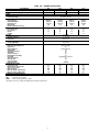
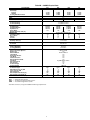
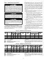
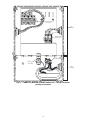
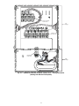
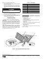
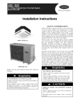
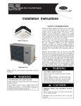
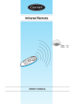
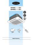
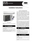
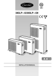
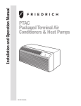
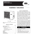
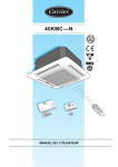
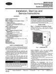
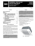
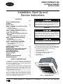
40KMC,40KMQ018-036
In-Ceiling Cassette
Fan Coil Units
Installation, Start-Up and
Service Instructions
CONTENTS
Page
SAFETY CONSIDERATIONS . . . . . . . . . . . . . . . . . . . . . . 1
GENERAL . . . . . . . . . . . . . . . . . . . . . . . . . . . . . . . . . . . . . . . . 1
INSTALLATION . . . . . . . . . . . . . . . . . . . . . . . . . . . . . . . . 2-19
Step 1 — Complete Pre-Installation Checks . . . . . . 2
• UNPACK UNITS
• INSPECT SHIPMENT
• CONSIDER SYSTEM REQUIREMENTS
Step 2 — Locating and Mounting the Unit . . . . . . . . 6
• LOCATING THE UNIT
• MOUNTING THE UNIT
Step 3 — Locating and Mounting the Room
Controller . . . . . . . . . . . . . . . . . . . . . . . . . . . . . . . . . . . . . . 8
• LOCATING THE ROOM CONTROLLER
• MOUNTING THE ROOM CONTROLLER
Step 4 — Complete Refrigerant Piping
Connections . . . . . . . . . . . . . . . . . . . . . . . . . . . . . . . . . . 10
• FLARING THE ENDS OF PIPES
• PIPING CONNECTION TO THE UNIT
Step 5 — Make Electrical Connections . . . . . . . . . . 11
• UNITS WITH ELECTRIC HEATER
• POWER WIRING
• WIRING THE ROOM CONTROLLER
INSTALLATION OPTIONS. . . . . . . . . . . . . . . . . . . . . 19-23
Fresh Air Intake . . . . . . . . . . . . . . . . . . . . . . . . . . . . . . . . . 19
Conditioned Air Supply to Adjacent Room . . . . . . 19
Room Controller Configuration Setup . . . . . . . . . . . 21
Louver Mode Selection. . . . . . . . . . . . . . . . . . . . . . . . . . 22
Main Board Configuration . . . . . . . . . . . . . . . . . . . . . . . 22
Service Test Mode. . . . . . . . . . . . . . . . . . . . . . . . . . . . . . . 22
START-UP . . . . . . . . . . . . . . . . . . . . . . . . . . . . . . . . . . . . . . . 23
SERVICE AND MAINTENANCE . . . . . . . . . . . . . . .23,24
TROUBLESHOOTING. . . . . . . . . . . . . . . . . . . . . . . . . . . . 24
Before installing or servicing system, always turn off main
power to system. There may be more than one disconnect
switch. Turn off accessory heater power if applicable. Electrical shock can cause serious personal injury.
GENERAL
This system uses Puron® R-410A, which has higher pressures than R-22 and other refrigerants. No other refrigerant
may be used in this system. All equipment must be
designed to handle R-410A refrigerant. If unsure about
equipment, consult the equipment manufacturer.
Do not operate the unit without a filter or with the grille
removed. Damage to the unit or personal injury may result.
These instructions cover the installation, start-up and
service of in-ceiling cassette fan coil units. See Fig. 1.
The following accessories can be used with 40KMC,KMQ
units. See the price pages part numbers and more information:
• photocatalytic and electrostatic filter with mount
• air supply outlet obstruction kit
• wired room controller
• room controller wiring kit for multiple units
• zone manager kit for multiple units
• zone manager
• infrared remote kit
SAFETY CONSIDERATIONS
Installing and servicing air-conditioning equipment can be
hazardous due to system pressure and electrical components.
Only trained and qualified service personnel should install or
service air-conditioning equipment.
Untrained personnel can perform basic maintenance, such
as cleaning and replacing filters. All other operations should be
performed by trained service personnel. When working on air
conditioning equipment, observe safety precautions in literature, tags, and labels attached to unit.
Follow all safety codes. Wear safety glasses and work
gloves. Use quenching cloth for brazing operations. Have fire
extinguisher available. Read these instructions thoroughly.
Consult local building codes and the National Electrical Code
(NEC) for special installation requirements.
Fig. 1 — 40KMC,KMQ Unit
Manufacturer reserves the right to discontinue, or change at any time, specifications or designs without notice and without incurring obligations.
Catalog No. 02-40QK0001-SI
Printed in U.S.A.
Form 40KM-1SI
Pg 1
606
3-06
Replaces: New
Book 1 4
Tab 3d 2d
CONSIDER SYSTEM REQUIREMENTS — Consult local
building codes and NEC for special installation requirements.
Use only designated indoor units with outdoor units. See
Tables 2-4B.
See Fig. 2 for unit dimensions. Allow sufficient space for
airflow clearance, wiring, refrigerant piping, and servicing
units.
Avoid mounting the unit in areas that are:
• exposed to direct sunlight
• too close to heat sources
• damp or areas exposed to water
• located in areas that could obstruct air circulation, such
as near curtains or furniture
INSTALLATION
Step 1 — Complete Pre-Installation Checks
UNPACK UNIT (See Fig. 1) — Move the unit to final location. The grille panel and the remote control are separately
packed for maximum protection. Remove unit from carton, being careful not to lift the unit by the condensate drain discharge
pipe or by the refrigerant connections. Handle by the four
corners of the unit. See Table 1 for field-supplied materials
required for installation.
INSPECT SHIPMENT — File a claim with the shipping
company if shipment is damaged or incomplete. Check the unit
nameplates to ensure units match job requirements.
Table 1 — Field Supplied Installation Materials
NAME
Connection Pipe
Wall Sleeve
Wall Cap
Finishing Tape
Fastening Tape
Tube Insulation
Drain Hose
Sealer Putty
Outdoor Power Supply Cable
Control Wire Electrical Connecting Cable
Between Indoor and Outdoor Unit
Wire nuts
Conduit
SPECIFICATIONS
40KMC018,024,KMQ01824: 5/8 in. (Mixed Phase)/3/8 in. (Liquid)
40KMC/KMQ03036: 3/4 in. (Mixed Phase)/3/8 in. (Liquid)
—
—
PVC Film
—
—
1 in. ID
—
40KMC018-036: AWG 14
40KMQ018-036: AWG 12
Cable Type: AWG 22 synthetic rubber insulation with
Neoprene coating, according to NEC codes.
—
—
LEGEND
AWG — American Wire Gage
NEC — National Electrical Code
Table 2 — Matching Indoor Units to Outdoor Units*
SYSTEM
TYPE
SYSTEM SIZE
018
024
030
036
018
024
030
036
018
024
030
036
Cooling Only
Cooling with
Electric Heat
Heat Pump
OUTDOOR
UNIT
38HDF018
38HDF024
38HDF030
38HDF036
38HDF018
38HDF024
38HDF030
38HDF036
38QRF018
38QRF024
38QRF030
38QRF035
INDOOR UNIT
MODEL NUMBER
40KMC018---3
40KMC024---3
40KMC03036---3
40KMC03036---3
40KMQ01824-3
40KMQ01824-3
40KMQ03036-3
40KMQ03036-3
40KMQ01824-3
40KMQ01824-3
40KMQ03036-3
40KMQ03036-3
INDOOR UNIT
GRILLE ITEM NUMBER
40KMC9005
40KMC9006
40KMC9006
40KMC9006
40KMC9006
40KMC9006
40KMC9006
40KMC9006
40KMC9006
40KMC9006
40KMC9006
40KMC9006
*All units use R-410A refrigerant only.
Table 3 — AccuRator* Control Sizes and Refrigerant Charge Requirements
SYSTEM
TYPE
Cooling Only
Cooling with
Electric Heat
Heat Pump
SYSTEM
SIZE
018
024
030
036
018
024
030
036
018
024
030
036
COOLING
ACCURATOR
0.049
0.057
0.061
0.074
0.049
0.057
0.061
0.074
0.051
0.055
0.063
0.07
HEATING
ACCURATOR
—
—
—
—
—
—
—
—
0.046
0.053
0.055
0.063
ACCURATOR
TYPE
B
B
B
B
B
B
B
B
B
B
B
B
FACTORY
CHARGE† (lb)
4.8
5.3
5.0
7.0
4.8
5.3
5.0
7.0
5.5
6.9
10.7
10.5
*AccuRator controls are for outdoor units. See the outdoor installation instructions for more information.
†The outdoor unit is either fully charged or under charged from the factory.
2
ADDITIONAL FIELD
CHARGE REQUIRED† (lb)
0.0
1.2
3.0
2.3
0.0
1.2
3.0
2.3
0.0
0.0
1.8
0.0
1ʼ 10-5/8ʼʼ(575)
1' -10-5/8"(575)
3/8"(9)
Return air
2-13/64"(56)
9 -9/16"(243)
1 -5/16"(49)
5 -5/16"
(135)
32
9/
Supply air
Supply air
0' -7-7/32"(158)
4"(102)
Ø 2-3/14" (70)
1-11/16"(43)
Ø
)
6"(153)
"(
2
5-
0
15
4-3/4"(120)
8-55/64"(225)
11"(280)
11-3/4"(298)
2"(52)
2'-4-11/32"(720)
1'-9-21/32"(550)
"
/16
1- 330)
(
1'-8 9/32"(515)
40KMC018
Ø1"(25)
2"
)
(50
1-7/8"(47)
Return air
15/16"(24)
Supply air
Supply air
1'-11-7/16"(595)
5-29/32"(150)
40KMC024-036 / 40KMQ018-036
Ø1"(
25)
1-
15
/1
6"
(4
9)
Fig. 2 — Unit Dimensions
3
3'-1-51/64"(960)
8)
(4
8"
7/
6)
(6
8"
5/
2-
NOTE: Dimensions in ( ) are in mm.
2'-8"(813)
Ø3-15/16"
(100)
9-11/32"(237)
1 -31/32"
(50)
11-57/64"
(302)
6-5/8"(168)
6"(153) 5"(128)
4-3/4"(120)
1'(305)
)
50
(1
2"
3
/
9
-2
Ø5
6"
(152)
2'-8-1/2"(825)
2'-8-1/2"(825)
Table 4A — 40KMC Physical Data
SYSTEM SIZE
NOMINAL CAPACITY (Btuh)
OPERATING WEIGHT (lb)
SEER
REFRIGERANT*
Control (Cooling)
INDOOR FAN
Rpm/Cfm High
Rpm/Cfm Medium
Rpm/Cfm Low
Motor Watts
Blowers Quantity...Size (in.)
INDOOR COIL
Face Area (sq ft)
No. of Rows
Fins/in.
Circuits
FILTERS
Quantity...Size (in.)
AIRSWEEP
Horizontal
OPERATING LIMITS
Cooling (Min/Max)
CONTROLS
Remote Controller Options
Diagnostics
Defrost Method
Timer Mode
Warm Start Feature
Test Mode
Freeze Protection
Dehumidification Mode
Fan Mode
Auto Changeover
Auto Restart
Control Voltage
System Voltage
REFRIGERANT LINES
Connection Type
Mixed-Phase Line (in.) OD
Vapor Line (in.) OD
Max Length (ft)
Max Lift (Fan Coil Above) (ft)
Max Lift (Fan Coil Below) (ft)
CONDENSATE DRAIN SIZE (in.)
018
17,000
49
1000/470
890/420
730/340
120
3.2
2
22
5
024
23,600
91
030
29,000
95
13
R-410A
AccuRator Control
Direct Drive Centrifugal
440/690
660/910
360/560
550/760
300/470
470/670
110
210
1...11.1
Copper Tube, Aluminum Fin
4.8
4.6
2
3
18
18
6
10
Cleanable
1...17 x 16
036
36,400
95
660/910
550/760
470/670
210
4.6
3
18
10
Auto/Preset
55 F/125 F
Integrated Microprocessor
Wireless, CRC
Yes
Demand Defrost
Yes
Yes
Yes
Yes
Yes
High/Medium/Low/Auto
Yes
Yes
24
208/230
Flare
3/
8
5/
8
200
60
60
1
LEGEND
CRC — Carrier Room Controller
SEER — Seasonal Energy Efficiency Ratio
*See Table 3 for factory charge and additional field charge requirements.
4
Flare
3/
8
5/
8
200
60
60
1
Flare
3/
8
3/
4
200
60
60
1
Flare
3/
8
3/
4
200
60
60
1
Table 4B — 40KMQ Physical Data
SYSTEM SIZE
NOMINAL CAPACITY (Btuh)
Heat Pump
Cooling
Heating
Cooling with Electric Heat
SEER
HSPF
OPERATING WEIGHT (lb)
REFRIGERANT*
Control (Cooling)
Control (Heating)
INDOOR FAN
Rpm/Cfm High
Rpm/Cfm Medium
Rpm/Cfm Low
Motor Watts
Blowers Quantity...Size (in.)
INDOOR COIL
Face Area (sq ft)
No. of Rows
Fins/in.
Circuits
FILTERS
Quantity...Size (in.)
AIRSWEEP
Horizontal
OPERATING LIMITS
Heating (Min/Max)
Cooling (Min/Max)
CONTROLS
Remote Controller Options
Diagnostics
Defrost Method
Timer Mode
Warm Start Feature
Test Mode
Freeze Protection
Dehumidification Mode
Fan Mode
Auto Changeover
Auto Restart
Control Voltage
System Voltage
REFRIGERANT LINES
Connection Type
Mixed-Phase Line (in.) OD
Vapor Line (in.) OD
Max Length (ft)
Max Lift (Fan Coil Above) (ft)
Max Lift (Fan Coil Below) (ft)
CONDENSATE DRAIN SIZE (in.)
018
024
030
036
17,900
16,800
17,000
22,600
20,800
22,600
29,200
27,400
29,000
33,400
32,400
36,000
13
7.7
91
440/690
360/560
300/470
110
4.8
2
18
6
91
95
R-410A
AccuRator Control
AccuRator Control
Direct Drive Centrifugal
440/690
660/910
360/560
550/760
300/470
470/670
110
210
1...18
Copper Tube, Aluminum Fin
4.8
4.6
2
3
18
18
6
10
Cleanable
1...24 x 235/16
95
660/910
550/760
470/670
210
4.6
3
18
10
Auto/Preset
15 F/75 F
55 F/125 F
Integrated Microprocessor
Wireless CRC
Yes
Demand Defrost
Yes
Yes
Yes
Yes
Yes
High/Medium/Low/Auto
Yes
Yes
24
208/230
Flare
3/
8
5/
8
200
60
60
1
LEGEND
CRC — Carrier Room Controller
HSPF — Heating Seasonal Performance Factor
SEER — Seasonal Energy Efficiency Ratio
*See Table 3 for factory charge and additional field charge requirements.
5
Flare
3/
8
5/
8
200
60
60
1
Flare
3/
8
3/
4
200
60
60
1
Flare
3/
8
3/
4
200
60
60
1
(supplied with the unit) may be used as a guide. Depending on
the type of ceiling, the hangers can be fixed as shown in Fig. 5.
Once the threaded hangers have been positioned, do not
tighten the nuts. Insert the washers as shown in Fig. 5. First
position the refrigerant lines, as described in the Complete
Refrigerant Piping Connections section. Remove the “T” bar in
the ceiling to facilitate installation. See Fig. 6.
Carefully lift the unit (without the frame) using the four suspension brackets (or the four corners), and insert it into the
false ceiling. If the “T” bar cannot be removed from the ceiling
the unit may need to be tilted. See Fig. 7.
NOTE: Tilting the unit may only be carried out with false ceilings with a minimum height of 11 ft-13/16 inches.
Align and level the unit by adjusting the nuts and locknuts on
the threaded hangers, maintaining a distance of 1 in. to 13/16 in.
between the sheet metal body and the underside of the false ceiling. See Fig. 8. Reposition the “T” bar and align the unit in
relation to the bar by tightening the nuts and locknuts. After
connection of the condensate drain line and the refrigerant lines,
carry out a final check to make sure that the unit is level.
Drilling the Hole for Connection Pipes in the External
Wall — After positioning the units and determining the connection position, drill a 23/4 in. hole in the wall. The same hole
can be used as a condensate drain pipe conduit. The hole
should have a 3/16 in. to 3/8 in. slope toward the outside. Refer
to Fig. 9. Insert the plastic conduit. Pass the power connection
cables through the conduit The power connection cables will
be connected in the Make Electrical Connections section.
Running the Condensate Drain Piping — To ensure correct
condensate water flow, the drain pipe should have a gradient of
2% without obstructions. Additionally, a trap of at least 2 in.
depth should be made to prevent unpleasant odors from reaching the room.
Step 2 — Locating and Mounting the Unit
LOCATING THE UNIT — Install the unit as centrally as
possible in the room. The air flow direction can be controlled
by the remote control (where used) or automatically, according
to the unit operating mode (cooling or heating). Controlling
the airflow automatically will ensure optimum distribution of
the air in the room.
In Cooling mode, the louvers should be positioned so that
the air is directed towards the ceiling. Refer to Fig. 3. In Heating mode, the louvers should be positioned so that the air is directed toward the floor to prevent layers of hot air forming
close to the ceiling. Refer to Fig. 3. The louvers will be automatically positioned when the louvers are set to Automatic
mode. Alternatively, the louvers can be placed in intermediate
positions (with infrared remote accessory kit only) or allowed
to move continuously (Swing mode).
In order to allow easy and rapid installation and maintenance, ensure that the unit is mounted in a location that is easily
accessible.
Restricting Air Outlets — A maximum of two air outlets can
be restricted at one time. See Fig. 3. The air supply outlet obstruction accessory kit can be used to obstruct air outlets. Contact your local dealer for more information.
MOUNTING THE UNIT — Use a stacker to lift the unit to
the installation location. Refer to Fig. 4. If the mounting location is in a plaster board ceiling, the maximum dimensions of
the unit housing cutout must not exceed 2 ft, 2 in. square for
40KMC018 units and 2 ft, 11 in. square for 40KMC024,03036
and 40KMQ01824,03036 units.
NOTE: In rooms with high humidity, brackets should be
insulated using self adhesive insulation.
Mark the position of the hangers, refrigerant lines and
condensate drain pipe, power supply cables and remote control
cable (see Fig. 2 for dimensions). The cardboard template
Max. 2 louvers closed
Heat pump: louver position for correct airflow.
Cooling: louver position for correct airflow.
Fig. 3 — Louver Positioning
6
Spirit
Level
False
Ceiling
1“ to 1-3/16”
Fig. 4 — Positioning Unit
2-3/4"÷3"
(70/80 mm)
Fig. 8 — Align and Level the Unit
Outdoor
3/16"÷3/8"
(5÷10 mm)
Indoor
Nut
Washers
Threaded hangers
Wooden frame
Nut
Washer
Threaded hangers
Washer
Nut
Nut
Fig. 9 — Drilling for Connections
The condensate may be discharged at a maximum height of
77/8 in. above the unit, as long as the ascending tube is vertical
and aligned with the drainage flange.
If it is necessary to discharge the condensate from a level
above 77/8 in., install an auxiliary water discharge pump and
float valve. A float valve is recommended to stop the compressor if there is a fault at the auxiliary pump.
The condensate pipe must be insulated with condensation
proof material such as polyurethane, propylene or neoprene of
3/ in. to 3/ in. thickness. See Fig. 10.
16
8
Fig. 5 — Attaching Hangers to Ceiling
Threaded hangers
"T" bar
(to be removed)
The drain tube extension must be securely fastened to the
condensate drain. Failure to do so could result in condensate water dripping on to the floor, which could cause personal injury.
Fig. 6 — Threaded Hangers and T Bar
NOTE: If more than one unit is installed in the room, the drain
system can be designed as shown in Fig. 10.
Installing the Grille and Frame Assembly — Carefully unpack the assembly and check for damage sustained in transport.
Attach the assembly to the unit by using the two hooks. See
Fig.11. Tighten the four screws, link the electrical connectors
and insert the wires in the cable clamp. Use the screws supplied
to fix the frame in to position. See Fig. 12.
Ensure that the frame is not distorted by excessive tightening, that it is aligned with the false ceiling and that there is a
seal between the air inlet and outlet. See Fig. 13. Gasket “A”
prevents return air from mixing with the supply air and gasket
“B” prevents the supply air from leaking into the ceiling void.
Once the unit is mounted in the ceiling, the gap between the
unit frame and the false ceiling must not be more than 3/16 in.
wide.
Threaded Hangers
Threaded Hangers
T-Bar
T-Bar
T-Bar
Supension Brackets
Supension Brackets
Fig. 7 — Positioning Unit in Ceiling
7
2%
2” (50 mm)
A. Gasket "A"
B. Gasket "B"
max. 7-7/8”(200 mm)
A
AIR B
Fig. 10 — Condensate Drain Pipe
Fig. 13 — Gasket Location
Frame support brackets
Step 3 — Locating and Mounting the Room
Controller
Electrical shock can cause personal injury and death. Shut
off all power to this equipment during installation. There
may be more than one disconnect switch. Tag all disconnect locations to alert others not to restore power until work
is completed.
Fig. 11 — Attach Frame Assembly
LOCATING THE ROOM CONTROLLER — See Fig. 14
for room controller dimensions. If the air sensor in the room
controller is going to be used, the room controller should be
located by considering the following:
• Position controller with a minimum clearance of 5 ft from
the floor.
• Locate the unit in the same area as the fan coil unit; preferably on an inside partitioning wall.
• Locate on a section of the wall without pipes or ductwork.
• Do not locate close to a window, on an outside wall, or next
to a door leading to the outside.
• Do not locate where the controller is exposed to direct light
and heat from a lamp, sun, fireplace, or other temperatureradiating object that may cause a false reading.
• Do not locate close to, or in direct airflow of, a heating or
cooling supply.
• Do not locate in areas with poor circulation, such as behind
a door or in an alcove.
NOTE: Do not exceed 500 ft of network wiring when mounting the room controller.
Safety cord
Cable clamp
Power connection
cables from unit
Power connection
cables from frame
Frame support
screws
Fig. 12 — Fix Frame in Position
8
3/4"(20mm)
2-3/4"(70mm)
4-1/4" (108mm)
Fig. 14 — Room Controller Dimensions
Push any excess wire into the wall and against mounting
base. If the air sensor is being used on the room controller, seal
the hole in the wall to prevent air leaks. Leaks can affect sensor
operation.
Push the room controller snap hinge to the base and tighten
the side fixing screw.
MOUNTING THE ROOM CONTROLLER (Fig. 15-17) —
Unscrew the side fixing screw. Open the room controller rear
mounting base to expose the mounting holes. The base can be
removed to simplify mounting (snap apart carefully at hinge to
separate mounting base from the rest of the room controller).
Route the room controller wires through the large hole in the
mounting base. Level the mounting base against the wall (for
aesthetic value only, as the room controller does not need to be
level for proper operation) and mark the wall through the two
mounting holes. Drill two 3/16 in. mounting holes in the wall
where marked. Secure the mounting base correctly (UP) to the
wall with the two screws and two anchors provided, (additional
anchoring holes are available for more secure mounting if necessary) making sure all wires extend through the hole in the
mounting base. Adjust the length and routing of each wire to
reach the proper terminal in the connector block on the mounting base, with 1/4 in. of extra wire (strip only 1/4 in. of insulation
from each wire to prevent adjacent wires from shorting together when connected).
Match and connect equipment wires to proper terminals
in the connector block. Both power and communication
wires must be connected correctly for proper room controller
operation.
P
G
C
Connection Cable
Fig. 16 — Locating the Connection Cable
P
G
C
Mounting screws
P
G
C
Connection Cable
Fig. 15 — Mounting the Room Controller
Fig. 17 — Connecting the Room Controller
9
Step 4 — Complete
Connections
Refrigerant
If either refrigerant tubing or indoor coil is exposed to
the atmosphere, the system must be evacuated following good
refrigeration practices.
Piping
IMPORTANT: During unit installation make the refrigerant
connections first and then the electrical connections. If the
unit is uninstalled, disconnect the electrical cables first and
then the refrigerant connections. Refer to the outdoor unit
installation instructions for tube sizing and limitations.
Use field-supplied refrigerant grade piping designed for use
with R-410A refrigerant.
FLARING THE ENDS OF PIPES — Remove the protective caps from the copper pipe ends. Holding the tube downward, cut the extreme end off, removing any copper shavings
with a deburring blade. Remove the flare nuts from the
“FLARE” connection body of the indoor unit and insert them
into the pipes. Make the flare to the pipe end with the proper
flaring tool. The flare end must not have any burrs or imperfections. The length of the flared walls must be uniform. See
Fig. 18 and 19.
Lubricate the end of pipe and the thread of the flare connection with anti-freeze oil. Tighten by hand and then use two
wrenches to tighten all connections fully, applying the tightening torque shown in Table 5. Refer to Fig. 20.
Fig. 18 — Removing Burrs
L
TUBE
DIAMETER
(in.)
3/ in.
8
5/ in.
8
3/ in.
4
L
Table 5 — Tightening Torque
TORQUE
(ft-lb)
31
48
74
PIPING CONNECTION TO THE UNIT — Use two wrenches to tighten all connections.
Insufficient tightening torque could cause a refrigerant leak
from the connection. Excessive tightening torque will damage the pipe flare.
Once all connections have been completed, check for leaks
using soapy water. If no leaks were found, wrap connections
with anti-condensate insulation and tighten with tape, without
exerting excessive pressure on the insulation. Repair and cover
any possible cracks in the insulation.
Fig. 19 — Flared Walls are Equal
1
DO NOT BURY MORE THAN 36 IN. OF REFRIGERANT PIPE IN THE GROUND. If any section of pipe is
buried, there must be a 6-in. vertical rise to the valve
connections on the outdoor unit. If more than the
recommended length is buried, refrigerant may migrate to
cooler, buried section during extended periods of system
shutdown. This causes refrigerant slugging and could
possibly damage the compressor at start-up.
3
Adjustable wrench or torque wrench
Outdoor end
Indoor end
2
Fig. 20 — Tightening Connections
10
POWER WIRING (Fig. 21-27) — The unit is factory wired
for voltage shown on nameplate. Provide adequate, fused disconnect switch within sight of unit, readily accessible, but out
of reach of children. Provision for locking the switch open
(off) is advisable to prevent power from being turned on while
unit is being serviced. Disconnect switch, fuses, and field
wiring must comply with the NEC and local code requirements. Use copper wire only between the disconnect
switch and unit. Use minimum 60 C wire for the field power
connection.
Remove the external box cover. Route the low voltage wires
from the outdoor unit to the indoor unit:
1. Place wiring through 7/8 in. knockouts on the left or right
hand side of external control box (low voltage side).
2. Connect the R and Y wires to the 2 pin terminal block for
cooling only units (40KMC) and heat pump units
(40KMQ) that are matched to 38HDF outdoor units.
3. Connect the R, Y, O, G, DT, A, and B wires to the
(PGB-1) 1 terminal for 40KMQ indoor units matched
with 38QRF outdoor units.
Route the line power leads from the indoor disconnect to the
fan coil unit.
1. Place wiring through 7/8 in. or 11/8 in. knockouts on the
left and on the right hand side of external control box
(high voltage side).
2. Connect L1 to the black wire and L2 to the red wire using
wire nuts and fix the ground wire between the 2 washers.
See Fig. 27 for a view of the internal control panel. The internal control panel can be accessed by opening the grille and
removing the metal cover attached by four screws.
NOTE: The internal control panel does not need to be accessed
during the installation process unless there is a need for
service.
Step 5 — Make Electrical Connections
Unit cabinet must have an uninterrupted, unbroken electrical ground to minimize the possibility of personal injury if
an electrical fault should occur. This ground may consist of
electrical wire connected to unit ground lug in control compartment, or conduit approved for electrical ground when
installed in accordance with NEC, and local electrical
codes. Failure to follow this warning could result in the
installer being liable for the personal injury of others.
Unit failure as a result of operation on improper line
voltage or excessive phase imbalance constitutes abuse and
may cause damage to electrical components. Such operation would invalidate any applicable Carrier warranty.
Electrical shock can cause personal injury and death. Shut
off all power to this equipment during installation. There
may be more than one disconnect switch. Tag all disconnect locations to alert others not to restore power until work
is completed.
See Tables 6A and 6B for electrical information.
UNITS WITH ELECTRIC HEATER — The unit is equipped
with two thermostats: one with automatic reset and one with
manual (electric) reset that can be reactivated by switching the
power supply off and then back on.
Table 6A — 40KMC Fan Coil Electrical Data
VOLTAGE
RANGE*
40KMC
UNIT
SIZE
V-PH-Hz
018
024
030
036
208/230-1-60
208/230-1-60
208/230-1-60
208/230-1-60
AWG
FLA
MCA
MOCP
NEC
—
—
—
—
—
FAN
Min
Max
FLA
187
187
187
187
253
253
253
253
0.55
0.50
0.95
0.95
Motor
Power
(Watts)
120
110
210
210
POWER
CONDENSATE
PUMP
FLA
LOUVER
MOTOR
FLA
MCA
MOCP
MIN WIRE
SIZE
AWG
0.06
0.06
0.06
0.06
0.01
0.01
0.01
0.01
0.8
0.7
1.3
1.3
15
15
15
15
14
14
14
14
LEGEND
American Wire Gage
Full Load Amps
Minimum Circuit Amps per NEC Section 430-24
Maximum Overcurrent Protection
National Electrical Code
*Permissible limits of the voltage range at which unit will operate
satisfactorily.
NOTE: In compliance with NEC requirements for multimotor and
combination load equipment (refer to NEC Articles 430 and 440),
the overcurrent protective device for the unit shall be fuse or
equipped with a breaker.
Table 6B — 40KMQ Fan Coil Electrical Data
VOLTAGE
RANGE*
40KMQ
UNIT
SIZE
V-PH-Hz
018
024
030
036
208/230-1-60
208/230-1-60
208/230-1-60
208/230-1-60
AWG
FLA
MCA
MOCP
NEC
—
—
—
—
—
FAN
Min
Max
FLA
187
187
187
187
253
253
253
253
0.50
0.50
0.95
0.95
Motor
Power
(Watts)
110.0
110.0
210.0
210.0
CONDENSATE LOUVER
PUMP
MOTOR
FLA
FLA
0.06
0.06
0.06
0.06
LEGEND
American Wire Gage
Full Load Amps
Minimum Circuit Amps per NEC Section 430-24
Maximum Overcurrent Protection
National Electrical Code
0.01
0.01
0.01
0.01
ELECTRIC
HEATERS
POWER
kW
FLA
MCA
MOCP
MIN
WIRE
SIZE
AWG
3
3
3
3
12.5
12.5
12.5
12.5
16.3
16.3
16.9
16.9
20
20
20
20
12
12
12
12
*Permissible limits of the voltage range at which unit will operate
satisfactorily.
NOTE: In compliance with NEC requirements for multimotor and
combination load equipment (refer to NEC Articles 430 and 440),
the overcurrent protective device for the unit shall be fuse or
equipped with a breaker.
11
Room Controller
Connections
Low
Voltage
Outdoor Unit
Connections
Power
Connections
Ground
Connection
High
Voltage
Fig. 21 — 40KMC Unit Matched to 38HDF Outdoor Unit — Wiring Connection
(Cooling Only System)
12
Room Controller
Connections
Low
Voltage
Outdoor Unit
Connections
Power
Connections
Ground
Connection
High
Voltage
Fig. 22 — 40KMQ Unit Matched to 38HDF Outdoor Unit — Wiring Connection
(Cooling with Electric Heat System)
13
Room Controller
Connections
Low
Voltage
Outdoor Unit
Connections
Power
Connections
Ground
Connection
High
Voltage
Fig. 23 — 40KMQ Unit Matched to 38QRF Outdoor Unit — Wiring Connection
(Heat Pump System)
14
NOTE 5
D I S P L AY
NOTE 6
T M-C O I L
T M-A I R
NOTE 4
M O D U L A R "D "
C O N T R O L 1P C B
B AR E C O P P E R
T O U N IT D IS C O N N E C T
(U S E C A B L E P R O V ID E D )
E Q U I P. G N D
4 0 K MC G L O B A L C A S S E T T E
38H D F O U T D O O R C O N D E N S E R
NO T E 7
E Q U IP G N D
2 0 8 /2 3 0 V
1P H
(S E E N O T E 9 )
T O O U T DO O R
U N IT D IS C O N N E C T
T O C AS S E T T E
T O C AS S E T T E
NO T E 8
LEGEND
1PCB
2PCB
C
CAP
CH
CHS
COMP
CRC
DP
EQUIP.
GND
FC
FS
GND
HPS
IFM
IR
ITP
LLPS
LM
LMS
— Main Control Printed
Circuit Board
— Display Board
— Contactor
— Capacitor
— Crankcase Heater
— Crankcase Heater Switch
— Compressor
— Carrier Room Controller
— Drain Pump
— Equipment Ground
—
—
—
—
—
—
—
—
Fan Capacitor
Float Switch
Ground
High Pressure Switch
Indoor Fan Motor
Infrared
Indoor Test Point
Liquid Low Pressure
Switch
— Louver Motor
— Louver Micro Switch
OFM
OL
S
TB
TM
TRAN
—
—
—
—
—
—
NOTES:
1. If any of the original wire furnished must be replaced, it must be
replaced with Type 90° C wire or its equivalent.
2. Wire in accordance with National Electrical Code (NEC) and local
codes.
3. Compressor and fan motors are protected by internal thermal
overloads.
4. Indoor unit transformer has internal 2A thermal fuse on the primary
side.
5. Infrared (IR) connection to be inserted on “J5” (replace the actual
factory-installed “CRC” connector) for IR option.
6. Terminal strip for Carrier Room Controller (CRC) connection.
7. Compressor crankcase heater installed on 38QRF035 and
38QRF030 only.
8. Outdoor unit transformer is factory wired for 230 v. For 208 v move
the black wire to the 208-v tap.
9. Use minimum 60° C wire for the field power wiring.
Outdoor Fan Motor
Overload
Emergency
Terminal Block
Sensor
Transformer
Terminal (Marked)
Terminal (Unmarked)
Splice
Terminal Block
Factory Wiring
Field Control Wiring
Field Power Wiring
Accessory or Optional Wiring
Plug Connector
THERMISTOR EQUIVALENCE
TEMPERATURE
RESISTANCE
°F
°C
Ω
95
35
6,500
72
22
11,400
32
0
32,500
NOTE: All thermistors are identical.
Fig. 24 — 40KMC/38HDF Cooling Only System Wiring Diagram
15
NOTE 5
D I S P L AY
NOTE 6
T M-C O I L
T M-A I R
NOTE 4
M O D U L A R "D "
C O N T R O L 1P C B
B AR E C O P P E R
T O U N IT D IS C O N N E C T
E Q U I P. G N D ( U S E C A B L E P R O V I D E D )
4 0 K MQ G L O B A L C A S S E T T E
38H D F O U T D O O R C O N D E N S E R
N O T E 7 E Q U IP G N D
2 0 8 /2 3 0 V
1P H
(S E E N O T E 9 )
T O O U T DO O R
U N IT D IS C O N N E C T
T O C AS S E T T E
T O C AS S E T T E
NO T E 8
NOTES:
1. If any of the original wire furnished must be replaced, it must be
replaced with Type 90° C wire or its equivalent.
2. Wire in accordance with National Electrical Code (NEC) and local
codes.
3. Compressor and fan motors are protected by internal thermal
overloads.
4. Indoor unit transformer has internal 2A thermal fuse on the primary
side.
5. Infrared (IR) connection to be inserted on “J5” (replace the actual
factory-installed “CRC” connector) for IR control.
6. Terminal strip for Carrier Room Controller (CRC) connection.
7. Compressor crankcase heater installed on 38QRF035 and
38QRF030F only.
8. Outdoor unit transformer is factory wired for 230 v. For 208 v move
the black wire to the 208-v tap.
9. Use minimum 60° C wire for the field power wiring.
LEGEND
1PCB
2PCB
3PCB
C
CAP
CH
CHS
COMP
CRC
DP
E-HTR
EQUIP.
GND
FC
FS
GND.
HPS
IFM
IR
ITP
LLPS
LM
— Main Control Printed
Circuit Board
— Display Board
— Printed Circuit Board for
Electric Heat
— Contactor
— Capacitor
— Crankcase Heater
— Crankcase Heater Switch
— Compressor
— Carrier Room Controller
— Drain Pump
— Electric Heater
— Equipment Ground
—
—
—
—
—
—
—
—
Fan Capacitor
Float Switch
Ground
High Pressure Switch
Indoor Fan Motor
Infrared
Indoor Test Point
Liquid Low Pressure
Switch
— Louver Motor
LMS
OFM
OL
S
ST
TB
TM
TRAN
—
—
—
—
—
—
—
—
Louver Micro Switch
Outdoor Fan Motor
Overload
Emergency
Safety Thermostat
Terminal Block
Sensor
Transformer
Terminal (Marked)
Terminal (Unmarked)
Splice
Terminal Block
Factory Wiring
Field Control Wiring
Field Power Wiring
Accessory or Optional Wiring
Plug Connector
THERMISTOR EQUIVALENCE
TEMPERATURE
RESISTANCE
°F
°C
Ω
95
35
6,500
72
22
11,400
32
0
32,500
NOTE: All thermistors are identical.
Fig. 25 — 40KMQ/38HDF Heat/Cool System Wiring Diagram with Electric Heaters
16
NOTE 5
D I S P L AY
NOTE 6
T M-C O I L
T M-A I R
O U T DR DE F R O S T
NOTE 4
M O D U L A R "D "
C O N T R O L 1P C B
B AR E C O P P E R
T O U N IT D IS C O N N E C T
E Q U I P. G N D ( U S E C A B L E P R O V I D E D )
4 0 K MQ G L O B A L C A S S E T T E
38Q R F O U T D O O R C O N D E N S E R
N O T E 7 E Q U IP G N D
2 0 8 /2 3 0 V
1P H
(S E E N O T E 9 )
T O O U T DO O R
U N IT D IS C O N N E C T
T O C AS S E T T E
T O C AS S E T T E
T O C AS S E T T E
T O C AS S E T T E
T O C AS S E T T E
T O C AS S E T T E
T O C AS S E T T E
T O C AS S E T T E
NO T E 8
LEGEND
1PCB
— Main Control Printed
Circuit Board
2PCB — Display Board
3PCB — Printed Circuit Board for
Electric Heat
C
— Contactor
CAP
— Capacitor
CH
— Crankcase Heater
CHS
— Crankcase Heater Switch
COMP — Compressor
CRC
— Carrier Room Controller
DFT
— Defrost Thermostat
DP
— Drain Pump
E-HTR — Electric Heater
EQUIP. — Equipment Ground
GND
FC
— Fan Capacitor
FS
— Float Switch
GND
— Ground
HPS
— High Pressure Switch
IFM
— Indoor Fan Motor
IR
— Infrared
ITP
— Indoor Test Point
LLPS — Liquid Low Pressure Switch
LM
— Louver Motor
LMS
— Louver Micro Switch
OAS
OFM
OFR
OL
RVS
S
ST
TB
TM
TRAN
—
—
—
—
—
—
—
—
—
—
Outdoor Air Sensor
Outdoor Fan Motor
Outdoor Fan Relay
Overload
Reversing Valve Solenoid
Emergency
Safety Thermostat
Terminal Block
Sensor
Transformer
Terminal (Marked)
Terminal (Unmarked)
Splice
Terminal Block
Factory Wiring
Field Control Wiring
Field Power Wiring
Accessory or Optional Wiring
NOTES:
1. If any of the original wire furnished must be replaced, it must be
replaced with Type 90° C wire or its equivalent.
2. Wire in accordance with National Electrical Code (NEC) and local
codes.
3. Compressor and fan motors are protected by internal thermal
overloads.
4. Indoor unit transformer has internal 2A thermal fuse on the primary
side.
5. Infrared (IR) connection to be inserted on “J5” (replace the actual
factory-installed “CRC” connector) for IR option.
6. Terminal strip for Carrier Room Controller (CRC) connection.
7. Compressor crankcase heater installed on 38QRF035 and
38QRF030F only.
8. Outdoor unit transformer is factory wired for 230 v. For 208 v move the
black wire to the 208-v tap.
9. Use minimum 60° C wire for the field power wiring.
THERMISTOR EQUIVALENCE
TEMPERATURE
RESISTANCE
°F
°C
Ω
95
35
6,500
72
22
11,400
32
0
32,500
NOTE: All thermistors are identical.
Plug Connector
Fig. 26 — 40KMQ/38QRF Heat Pump System Wiring Diagram with Electric Heaters
17
CA
C LR
CG
CP
CV
C G
CV
CP
C LR
CA
INTERNAL CONTROL PANEL
40KMC018
INTERNAL CONTROL PANEL
40KMC024-036
40KMC018-036
C apacitor
G MC board
E lectric heater board
(only on models with electric heater)
Transformer
Holes for fixing panel in position
E mergency push-button
CV
C LR
CG
CP
CA
Fig. 27 — Internal Control Panel
18
F an connector
LE D/R E C E IV E R connector
F loat connector
P ump connector
Louver connector
WIRING THE ROOM CONTROLLER — The room controller is capable of controlling from 1 to 6 fan coil units. The
total run length of the wire connecting the room controller to
the fan coil units should be kept to under 500 feet. Wire the
room controller to the unit using daisy chain wiring. See
Fig. 28. The room controller connects to the receiver board
connection on the electronic board inside the unit.
Wiring the Power Connection to the Room Controller — The
thermostat will be powered by unregulated nominal 12.5 volts
DC (10V min to 20V max) which is provided by the electronic
board inside the unit. The power consumption will be 50 mA
12.5 volts DC. For applications where more than one fan coil
unit is to be controlled, the fan coil unit closest to the room
controller will be the only one that supplies power to the room
controller. The control should be protected from damage in
case of accidental wiring of power, ground and signal wiring
occurs.
Wiring the Room Controller to the Indoor Unit — Loosen
the screws of terminals P (DC Power), G (GROUND) and C
(SIGNAL) on the indoor unit and room controller terminal
blocks. Refer to Fig. 29 and connect the indoor unit terminal
block to the room controller terminal block.
INSTALLATION OPTIONS
The 40KMC,KMQ units can be used to cool an adjacent
room or for fresh-air ventilation. Plan the installation carefully.
Measure carefully and follow acceptable building practices and
the National Electric Code (NEC).
Fresh Air Intake
1. Using Fig. 30, locate and remove the factory-installed insulation from the side of the unit where the prepunched
knockouts are located.
2. Remove the pre-punched knockouts for fresh air intake.
Refer to Fig. 30. Be careful not to damage internal parts
such as the heat exchanger coil.
3. If installing a 40KMC018 unit, install baffle. Refer to
Fig. 30.
4. Install ductwork using field-supplied, insulated flex duct,
or insulated sheet metal suitable for working temperatures up to 140 F. Conduits can be of flexible polyester
(with spiral core) or corrugated aluminum, externally
covered with anti-condensate material (fiberglass from
1/ in. to 1 in. thickness).
4
5. Use Fig. 31 to determine the allowable static pressure loss
for the ductwork airflow. The ductwork design must not
exceed this value or the job airflow requirements will not
be met.
6. Use a field-supplied fan if airflow does not meet job requirements. The field-supplied fan motor for outside air
intake must be controlled by a bipolar ON/OFF switch
with safety fuses.
FCU 1
REMOTE
FCU 2
IMPORTANT: Ventilated air must not exceed 10% of the
total airflow or problems with operation will result. If the
ventilated air surpasses 10% of the total airflow, a fieldsupplied primary air treatment system with separate deflectors is recommended.
FCU 3
FCU 6
7. Install an air inlet grille with filter inspection port to prevent dust and dirt from entering and fouling the indoor
unit heat exchanger. Filter installation also makes the installation of a duct closing damper during shutdown periods unnecessary.
8. All non-insulated ducts must be covered with anticondensate insulation (such as expanded neoprene, 1/4 in.
thickness).
Fig. 28 — Room Controller Daisy Chain Wiring
(Multidrop)
Diagram 1
Conditioned Air Supply to Adjacent Room —
Air supply to an adjacent room requires that the outlet corresponding with the duct is closed, using the air supply outlet
obstruction accessory kit.
NOTE: The accessory kit cannot be used in units equipped
with an electric heater.
An air inlet grille must be fitted (if possible near the floor)
between the air conditioned room (where the unit is situated)
and the adjacent room or, alternatively, the door must be undercut, as shown in Fig. 30. The duct lengths can be calculated in
accordance with Fig. 30, also taking into account the pressure
drop through air diffusers and fresh air filters.
R ed
B lack
White
A
R emote connector
(J5) 5 pins
A Indoor unit
B R oom C ontroller
P
G
C
B
P
G
C
Main electronic card
4 pins terminal block placed on external
control box
Wires supplied by the installer
Terminal block in the R oom C ontroller
Fig. 29 — Wiring the Room Controller to
the Indoor Unit
IMPORTANT: DO NOT use active carbon or electrostatic
filter kits for ducts towards adjacent rooms.
19
4.14” 4.72”
(105) (120)
1.93”
(49)
B
Ø
Ø
C
A
0”
8.5 6)
2
( 1
Ø
A
Unit
ØA
B
ØC
40KMC018
5-29/32"(150 mm)
40KMC024, 03036
40KMQ01824, 03036
5-29/32"(150 mm)
4-3/4"(120 mm)
4-3/4"(120 mm)
2-3/4"(70 mm)
3-15/16"(100 mm)
NOTE: Dimensions in ( ) are in mm.
Air intake grille
Wall
Undercut door
Wall-fitted grille
Door-fitted grille
Fig. 30 — Installation Options
20
Duct connection flange
Clip
1/4" (6 mm) neoprene gasket
Insulated flexible duct
Fresh air intake
Conditioned air supply to an
adjacent room
Polystyrene partition
Baffle (40KMC018 Only)
Frame
Supply air duct to adjacent room
External static pressure (in.wg)
0.18
0.16
0.14
0.12
40KMC,KMQ 03036
0.1
0.08
0.06
40KMC018,024
40KMQ01824
0.04
0.02
0
50
0
150
100
200
250
Airflow (cfm)
NOTE: When two louvers are closed, the fresh airflow towards the adjacent room is 50% higher than when
one louver is closed (with equal static external pressure).
Fig. 31 — Pressure Drop for Conditioned Air Supply to an Adjacent Room: One Louver Closed
Room Controller Configuration Setup — To configure the room controller, press the Mode button for 5 seconds. After 5 seconds, “10” will appear. This indicates that the
user is setting the first software configuration item. To display
the value of configuration item 10, press the Mode button
again. The value of the Heat/Cool vs Cooling only remote configuration will be displayed along with the “Set Temp” icon to
indicate that the number displayed is the configuration data.
Refer to Table 7 for configuration values. To change the Heat/
Cool vs Cooling only remote Configuration, press the Up and
Down buttons. To move to the next setting, press the Mode
button again and the “10” will be displayed. Press the up button
and the display will change to “11.” Refer to Fig. 32.
The Mode button will toggle the display between the items and
the configuration value. The Up and Down buttons will change
either the index or the value, whichever is displayed at the time.
Press the Fan button to exit the Configuration Setup Mode.
This mode will exit automatically after 10 seconds of inactivity. Once a configuration value is changed, the last value
displayed will be the new configuration value for the room
controller.
NOTE: The only way to abort a configuration change is to
change the value back to its original value.
1. Configuration Item 10: Heat Pump vs Cooling Mode
H — The Room Controller will allow and display the
following modes:
• Off
• Fan
• Auto
• Cool
• Dry
• Heat
C — The Room Controller will allow and display the following modes:
• Off
• Fan
• Cool
• Dry
2. Configuration Item 11: Room Thermistor Override
On — Room Thermistor Override is active. Units will be
controlled to the air temperature displayed via the Room
Controller.
Of (Off) — Room Thermistor Override is not active. All
units will be controlled to the room air thermistors located
on the units.
3. Configuration Item 12: Celsius vs Fahrenheit
C — Temperatures will be displayed in degrees Celsius.
F — Temperatures will be displayed in degrees Fahrenheit.
Table 7 — Room Controller Configuration Values
ITEM
10
VALUE
H*
C
On
11
Of*
C*
12
F
DESCRIPTION
Heat/Cool Remote
Cooling Only Remote
Room Thermistor Override
Active.
Control and display room air
temperature at the room
controller. Room Thermistor
Override Inactive. Do not
display room air temperature
at the room controller and
control to unit room air
thermistor(s).
Temperatures displayed in
degrees Celsius.
Temperatures displayed in
degrees Fahrenheit.
* Factory default.
21
Keep it pressed for
at least 5 seconds
Check the
value
Change the
value
up
down
Next
item
A
To check/change
the values of items
11 and 12 go back
to point A
up
down
Fig. 32 — Room Controller Configuration Steps
Louver Mode Selection — To enter louver mode
selection, ensure the room controller is on and then press the
Fan button for 5 seconds. After 5 seconds, the selected louver
setting will be displayed. Press the up and down arrows to
modify the louver setting between swing and auto. Refer to
Fig. 33. The two settings will be displayed as follows:
S with Swing Louver Icon
A with Auto Louver Icon
setting, press the Mode button again and the “20” will be
displayed. Press the Up button and the display will change to
“21.” The Mode button will toggle the display between the
software configuration item number (i.e., “20,” “21,” etc.) and
the configuration value. The Up and Down buttons will change
either the item number or the value, which ever is displayed at
the time.
This mode will exit automatically after 30 seconds of
inactivity.
NOTE: If units are grouped to one room controller, all units
will have the same configuration value.
Represents the swing louver
Represents the auto louver
The fan icon will also be displayed in the louver mode.
Press Fan button to exit the Louver Mode Selection. This mode
will exit automatically after 10 seconds of inactivity. The only
way to abort a louver change is to change the value back to its
original value.
NOTE: If units are grouped to one room controller, all units
will have the same louver value. Louver Mode selection is not
available during OFF mode.
Service Test Mode — Prior to start-up, conduct the
Service Test mode to ensure the unit is ready for start-up.
There is a hidden Service Test mode that is initiated through
a combination of button presses when the remote is off. The
following buttons need to be pressed, in sequence, within
6 seconds:
1. Down arrow
2. Fan button
3. Up arrow
4. Fan button
5. Mode button
Once in Service Test mode, the Service Test mode message
will be sent, and Sr will be displayed in the temperature icons
until the Down button is pressed. During Service Test mode all
the icons are off, and the only button that is active is the Down
button. To cancel Service Test mode, press the Down button to
send a message of Off mode to the unit. Service Test mode
automatically times out after 30 minutes and the remote will
operate normally.
When test mode is selected, the unit will operate as
described below:
• The Unit Status (Green) and Timer (Yellow) LEDs blink
every 2 seconds.
• The indoor fan will operate according to user-selected
speed. If user selected speed is Auto, the fan will run in
High speed.
• If the unit is configured as an A/C Only unit, it will operate
in cool mode with demand.
• If the unit is configured as a Heat Pump unit, the louver will
operate according to user-selected position. If user selected
louver is Auto, louver operates according to auto heat or
cool louver based on operating mode.
• The unit will run in cool mode for 3 minutes, then it will run
in heat mode for 2 minutes, or until the indoor coil is greater
than 104 F The unit will run in cool mode until test mode is
exited.
Main Board Configuration — To configure the main
electronic board, push the Up and Down arrows for 5 seconds
while the room controller is off.
After 5 seconds, a “20” will appear. This indicates that the
user is setting the first software configuration item. To check
the value of configuration item “20,” press the Mode button.
The value for the Heat Pump/AC Only configuration will be
displayed. To change the value, use the Up and Down buttons.
Once the desired value is selected, press the Fan button to send
that configuration data to the unit. Refer to Table 8.
Table 8 — Modular Platform D Unit Configuration
Values
ITEM
20
21
VALUE
1: Heat Pump
0: AC only (indoor unit with
or without electric heaters)
1-199 in increments of 1
COMMENT
Unit Configuration
defaults to heat pump
CCN Address of the unit.
Defaults to 1.
To display the hundreds,
push
22
0-199 in increments of 1
24
0: Start in Off mode
1: Start in last active mode
.
Zone number Communications zone
the system is located in
Defaults to 0
To display the hundreds,
push
.
Auto Restart
Defaults to “On”
Only the current value being displayed is transmitted. Once
the Fan button is pressed, the room controller will switch to
displaying the configuration item number. To move to the next
22
Room Controller
ON
up
Keep it pressed
for 5 seconds
down
To change
the value
Automatic
(AUTO)
Or
Continuous
movement
(swing)
Fig. 33 — Selecting the Louver Mode
Any of the following will cancel the Service Test mode:
• When the unit is turned off by the controller.
• If the power is cycled during the Test Mode, the unit will
return to its normal operating mode.
• After 30 minutes of receiving the last valid test request
message.
• Fail Mode.
Minimum Maintenance
1. Check, clean, or replace air filter each month or as
required.
2. Check cooling coil, drain pan, condensate trap, and condensate drain pan each cooling season for cleanliness.
Clean as necessary.
3. Check fan motor and wheel for cleanliness each heating
and cooling season.
4. Check electrical connections for tightness and controls
for proper operation each heating and cooling season.
Service as necessary.
START-UP
The following checks should be made before system startup. Refer to outdoor unit Installation, Start-Up, and Service
manual for system start-up instructions and refrigerant charging methods. Be sure to use the refrigerant charge shown in
Table 3.
1. Check condensate drainage system.
a. Remove grille and frame from the unit.
b. On the opposite side of the drain connection, insert
a water bottle up into the fan coil unit and fill drain
pan. Refer to Fig. 34. Water must flow regularly
with condensate pump energized. If water does
not, check the pipe slope or see if there are any
pipe restrictions.
NOTE: The unit is equipped with a safety float
switch to deenergize the compressor if the drain
water level gets too high.
2. Make sure that all wiring connections are correct and that
they are tight.
3. Make sure that all barriers, covers, and panels are in
place.
4. Ensure that the filters and return air grilles have been
installed and that the discharge louvers are correctly
positioned.
Service
TO CLEAN OR REPLACE AIR FILTERS
1. Place a plastic sheet on the floor to catch any water that
may spill from drain pan.
2. Slide filter out.
3. Vacuum clean or wash filter with soapy water. Rinse and
let air dry. If filter needs replacing, filters are available
from the local dealer.
If air filter is not replaced in the unit, dust and dirt gather in
air conditioner and operation becomes impaired.
Never operate unit without a filter or with grille removed.
Damage to the unit or personal injury may result.
SERVICE AND MAINTENANCE
Remove unit grille, filter, and condensate pan for cleaning,
lubricating, or replacing parts.
Fig. 34 — Inserting Water into Drain Pan
To avoid personal injury or damage to unit, do not service
until all power sources are shut down, locked out, and
tagged out. Failure to do so could result in personal injury
or unit damage.
23
TO CLEAN OR REPLACE DRAIN PAN
1. Place a plastic sheet on the floor to catch any water that
may spill from drain pan.
2. Remove the air intake and distribution assembly. Remove
the condensate water in the drain pan by pulling out the
rubber drain plug and letting water drain into a 3-gallon
bucket.
Do not use a screw driver to pry drain pan out of assembly.
It could damage the pan.
3. Remove screws holding the drain pan. Carefully hold the
drain pan to remove it from the assembly.
4. Re-install the drain pan using the appropriate number of
screws. Center and align the metal fan inlet orifice with
the fan. Ensure the fan spins freely.
TROUBLESHOOTING
See Table 9 and Fig. 35 for troubleshooting information.
Fault Code — Once a failure occurs with the indoor unit in
operation, the green LED on the indoor unit flashes at intervals
of 0.5 seconds. The fault code is deduced from the number of
times the green LED flashes, blocking unit operation. Between
one flash cycle and the next one, a pause of 5 seconds elapses.
See Fig. 34.
USING THE EMERGENCY BUTTON — The Emergency
button is for use by a qualified service technician only. The
Emergency button is for use when the room controller is inoperative. Use a screwdriver to press the emergency button
through the metal protection grille. See Fig. 35.
Table 9 — Fault Codes
CODE
2
3
4
6*
7
10
11
12
13
14
DESCRIPTION
Condensate discharge pump
Room air sensor fault
Indoor unit coil sensor fault
Filter dirty
Outdoor unit failure
EEPROM corrupt
Card serial number damaged
Address or zone incomplete
Gas flow distributor corrupt
Outdoor air thermistor fault
* When code is enabled.
Emergency Operation — When the unit is in the OFF mode
and the Emergency button is pressed for 5 seconds, the unit
will operate as follows:
• Automatic mode
• temperature preset to 72 F
• automatic fan speed
• louvers set automatically according to the operating mode
• Timer function is cancelled
• buzzer beeps
When the unit is ON and the Emergency button is pressed
for 5 seconds, the unit will operate as follows:
• the unit is turned off
• buzzer beeps
When a signal is received by the remote control, the unit
operates accordingly.
emote control
R ed G reen R
signal receiver
LE D
LE D
Yellow
LE D
E mergency
B utton
Fig. 35 — Warning Lamps and Emergency Button
Copyright 2006 Carrier Corporation
Manufacturer reserves the right to discontinue, or change at any time, specifications or designs without notice and without incurring obligations.
Catalog No. 02-40QK0001-SI
Printed in U.S.A.
Form 40KM-1SI
Pg 24
606
3-06
Replaces: New
Book 1 4
Tab 3d 2d