1
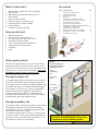
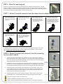
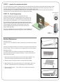
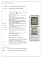
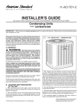
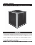
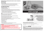
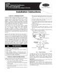
Breeze
™
A revolution in room cooling
Installation Instructions
for BR1224W3A
12000 - 24000 Btu
Friedrich Part No. 96091001
What’s in the carton?
Accessories
1. Breeze indoor module with 25 ft. connecting
line attached
2. Wall mounting template and bracket for indoor module
3. Breeze outdoor module
4. Outdoor module connection covers
5. Mounting pad for outdoor module
6. Remote control
7. Accessories (see list at right)
ITEM DESCRIPTION
1.
2.
3.
4.
5.
6.
7.
8.
9.
10.
11
12.
13.
14.
Tools you will need:
•
•
•
•
•
•
•
•
Phillips screwdriver
1/2” wrench or crescent wrench
Drill with Phillips bit and 3/16” drill bit
Stud finder (recommended)
3” hole saw (through wall installations)
Safety glasses (recommended)
Trim knife
Level
1.
QTY
CONTROL BOX COVER DOOR
CONTROL BOX COVER
QUICK CONNECT COVER
WIRE TIE
CONNECTING LINE BENDING GUIDE
ELECTRICAL CORD RETENTION BRACKET
WALL OPENING FILL GASKET
OUTDOOR UNIT ANCHOR SCREW
OUTDOOR UNIT WASHER FOR ANCHOR SCREW
SCREW #8 X 3/4” TRUSS HEAD
SCREW #6 -19X.375 HEX HEAD
WALL ANCHOR FOR #8 X 1 1/2” SCREW
SCREW #8 X 1 1/2” PHILLIPS PAN HEAD
CONNECTING LINE CLIPS
1
1
1
2
1
1
1
4
4
6
1
15
15
5
3.
2.
14.
13.
4.
9.
11.
10.
12.
8.
7.
6.
5.
Before getting started
Identify the locations where you will mount the indoor
module and place the outdoor module. Keep in mind,
there is 25’ of connection line for connecting indoor and
outdoor pieces, so locate them accordingly. You cannot
add additional length if they are too far apart.
Placing the indoor unit
It is recommended that you install the indoor module on
an exterior wall within 6 feet of a properly rated outlet
for the system you are installing. The BR1224W3A plugs
into a 230V 15A outlet. The system should be plugged
into a single circuit outlet only. Typically, hanging the
indoor module above or adjacent to a window will
provide a great location. NOTE: You should not drill
through the window header (part of the rough framing)
located directly above the window opening.
NOTE:
Be sure to place your
equipment with these
limitations in mind.
m
imu
min nce
"
in.
6 ara
6" m
cle
25 ft.
connecting
line
6 ft. power
cord
25 ft. max.
12" minimum
clearance
in.
6" m
6 ft.
power
cord
Placing the outdoor unit
The outdoor module should be placed on a level surface
with adequate clearance from items like shrubbery,
solid fencing or other air conditioning equipment that
can impede airflow to the module.
The outdoor module must be at least 12” from the wall
for proper airflow. The mounting pad provided with the
system will raise the module off of the ground 3”. The
fan should face away from the building.
DO NOT PLUG IN INDOOR UNIT until you have
completed the entire installation process.
CAUTION
SHOCK HAZARD - DO NOT PLUG-IN indoor unit until all installation work is completed!
Connect to a single dedicated circuit sized for the load.
DO NOT kink or bend refrigeration line-set less than 3” radius – A connecting line bending guide is provided.
Line-set is under high pressure – DO NOT Puncture line-set.
DO NOT Heat line-set.
Always follow all local and national codes when installing equipment. Obtain the help of trained, skilled
worker where necessary.
STEP 1 - Determine how you will connect the indoor and outdoor modules.
There are two options available:
OPTION 1 is to drill a 3” hole through the wall to pass
the connecting line through.
OPTION 2 is to use the Friedrich SimpleSill™ kit to pass
the connecting pipe through the window. The SimpleSill™ is an optional accessory available where Breeze
is sold.
DO NOT PLUG IN INDOOR UNIT until you have
completed the entire installation process.
Now that you have determined where the modules will be placed, it is time to install the Breeze air conditioning system.
STEP 2 – Hang wall mount bracket
Using the paper template as a guide, locate two studs
behind screw hole locations in the template. It is
preferable to mount the hanging plate on studs. If two
studs are not available, utilize anchors appropriate for
the wall type with a combined weight capacity of at least
60 lbs. Standard wood screws and drywall anchors are
provided.
If you are installing the system by drilling a 3” hole
through the wall (Option 1), mark the location of the 3”
hole centerline on the wall as well
Note that the indoor unit is not centered on the bracket.
There is a center line on the paper template which
shows where the center of the indoor unit will be after
installation.
STEP 3 – Drill hole (Option 1) or mount
SimpleSill™ (Option 2).
Always follow all local and national codes when installing equipment. Obtain the help of trained, skilled
worker where necessary.
Option 1: Drill hole Through-the-Wall Installation
Drill 3” hole through the exterior wall.
NOTE: This should only be done by qualified installers. Consult local and national codes before drilling any
holes. Mark the hole location on the indoor wall using
the template. (If locating unit above a window or door,
make sure the hole is above structural header)
NOTE: Wall mount bracket ships mounted to the back of the indoor
unit with a single Phillips head screw. Remove screw to release the
bracket for installation.
Paper template
3” hole location
NOTE:
Attach the wall
bracket to the wall
with at least two
screws capable of
securing at least
60 lbs.
Using a stud finder, scan area around desired hole location for pipes, ducts, electrical conductors and structural elements. Relocate indoor unit mounting location
as necessary to avoid interference.
Using a 3” hole saw, drill hole through wall from inside
toward outside. When hole saw cuts through inside wall,
stop drilling. DO NOT drill the entire 3” hole from the
inside to prevent insulation and exterior wall damage.
Depending on the type of insulation, it might be necessary to trim excess insulation prior to completing the
hole. Once insulation is removed, continue drilling from
inside until center drill bit of the saw just penetrates the
outside wall.
TIP: Tape a bag to the wall directly below hole location to
catch drill debris and dust or use a shop vacuum while
drilling.
Complete 3” hole from outside of the home by locating
center spiral drill bit penetration. Using the 3” hole saw
finish drilling through the wall from the outside of the
home.
3.1
Option 1 installation: remove
small knockout for power
cord only.
el
Lev
3.2
Option 2 installation: remove full
knockout for power cord and connecting line.
Option 2: Window Installation Using Friedrich SimpleSill™
1.
Be sure window sill is clean and free of dirt and debris. With the window raised,
place bottom seal gasket (trimmed to window width) firmly against window sill
(adhesive side down). Expand the SimpleSill™ 1” greater than the width of the window and install the securing pin. Place one end of the SimpleSill™ into the window
opening so it is against the corner of the window frame and sill. Raise the other
side of the SimpleSill™ 6-9 inches (depending on window width) above the window
sill. Next, press the raised side down until the SimpleSill™ is lodged securely into
position. The SimpleSill™ end gaskets will conform to the window track shape.
2.
Reference Step 4.2 and pass the connecting line out the window and insert it into
the connecting line form in the SimpleSill™.
3.
Install top seal gasket to the bottom of the window so it will seal against the top of
the SimpleSill.
4.
Replace the pass through cover.
5.
Insert securing pins.
6.
Lower window frame against SimpleSill compressing gasket.
7.
Depending on the type of window, install the appropriate security lock as recommended by manufacturer.
1.
4.
5.
STEP 4 - Line set installation
The Breeze connecting line set contains copper tubing that may kink if bent or formed incorrectly or repeatedly.
To avoid damaging your Breeze air conditioning system follow the 3 rules below throughout installation:
1) DO NOT uncoil and recoil the connecting line set more than two times.
2) DO NOT bend tubing in a radius smaller than 6”
3) ALWAYS use the tube bending guide when making bends greater than 45°
Following these instructions is critical for proper installation and to avoid damage to the unit. Damage to the
connecting line due to improper installation will not be covered by the warranty.
4.1 Option 1 (3” hole pass through)
Completely uncoil the line set as straight as possible. Starting with the quick connect end of the line set, pass the entire
length through the 3” hole. (Before installation break small plastic knockout on side of indoor unit for power cord to
pass through-see Step 3, Figure 3.1).
4.2 Option 2 (SimpleSill™ window installation)
STEP 5
Uncoil enough of the line set to completely pass through the SimpleSill. Pre bend
the line set using the enclosed template to match the desired shape as it passes
through the SimpleSill. Place remaining coiled line set outside the window for
later connection to the outdoor unit. Break full plastic knockout for line set to pass
through the side of the indoor unit-see Step 3, Figure 3.2.
STEP 5 - Hang the indoor module on the wall bracket.
Hang the module at the top first and rotate it down until the module is level with the
wall. (You may need to make adjustments to the connecting line to get the indoor
module to mount cleanly) The Breeze module is not designed to mount totally flush
to the wall. A space of 1/8” to 3/8” may be present between the module and the
wall.
The line set will sit in the recess of the
back of the indoor unit when mounted.
STEP 6 - Place the mounting pad.
STEP 6
Position the mounting pad so that the mounting holes are away from the house. Set the
outdoor module on the mounting pad so that the module feet align with the mounting holes.
Screw the outdoor module to the mounting pad with the 4 condenser pad installation washers
and screws provided (Items #8 and #9 in the Accessories List).
STEP 7 – Connect the quick connector from the indoor line set outdoor module.
1. Open lock handle on lineset connector by pulling
back and rotating toward
indoor unit.
2. Grasp outer lock collar on
line-set connector and pull
back until it stops.
5. Grasp lock handle and
rotate to its closed position.
6. Install security screw
(Item 13 in the Accessories
List) to prevent tampering
with line-set connector
mechanism.
3. While holding outer lock
collar rearward, push lineset connector body over
base connector on outdoor
unit half way and release
outer lock collar.
4. Continue to push line-set
connector onto base connector until outer lock collar engages base connector.
The outer lock collar will
snap into position with base
connector and a click will
be heard.
1.
If you have excess connecting line, roll the line into a coil approximately 2 feet wide,
secure with the provided wire ties and store between the outdoor module and the
wall. DO NOT cut or kink the connecting line!
2.
STEP 8 – Connect the electrical connector from the connecting
line to outdoor module
1.
Connect the black colored electrical connector from the connecting line into the
mating connector on the outdoor module. The connectors will snap into place with a
click. (The plug can be removed by pushing in the side tabs on the plug and pulling
the plug body down and out of the receptacle.)
Item #6
2.
Install the electrical cord retention bracket (Item #6 in the Accessories List) using Item #10
two #8 x 3/4” screws (Item #10 in the Accessories List). The opening in the electrical
cord retention bracket should fit over the cord. Do not pinch the cord in the bracket.
3.
Install the plastic cover (Item #2 in the Accessories List) as shown. There is one
screw located on the lower right flange of the cover and one screw under the electrical connector access cover. Once secure, use enclosed screw (Item #10 in the
Accessories List) to close the access door.
4.
Install the quick connect cover as shown in figure 4. Once in place secure using
enclosed #8 x 3/4” screw located on the top flange of the quick connect cover.
All Covers must be in place to operate unit.
SHOCK HAZARD exists without electrical access cover.
Cover cannot be installed without completing steps 8.1 through 8.4 properly.
3.
Item #10
STEP 9 – Locate the condensate drain.
The connecting line has a built in condensate line hose that removes the moisture collected from the indoor module.
The hose must be located in an appropriate location for drainage. Because the hose relies on gravity to drain, it is
important that the hose only points downward for the entire length of the hose.
If the connecting line is rolled to store the excess line as shown in Step 6, the drain line may be removed from the
connecting line as shown below and cut to an appropriate length.
SCORE AND PEEL
STEP 10 – Final Preparation.
Using the supplied connecting line clips (Item #14 in the
Accessories List), secure the connecting line to the interior and
exterior walls as desired. 5 retaining clips are provided from the
factory along with standard #8 x 1 1/2” screws and wall anchors.
For installations with the connecting line going through the wall
(option 1) use the supplied filler gasket (Item #7 in the Accessories
List) to plug the hole around the connecting line in the wall
opening. Additional sealing may be desired or necessary for
proper weatherproofing.
Once the connecting line is secure and Steps 1-9 are complete, you
may plug in the Breeze system and enjoy your new air conditioner.
STEP 9
Routine Maintenance
1.
Cleaning the unit:
The outer cover of the Breeze indoor module can be cleaned with a damp
cloth.
Cleaning the outdoor module can be done by rinsing the module with low
pressure water. Refer to friedrich.com for approved coil cleaning agents.
2.
Cleaning the filter:
The indoor module of the Breeze system has a washable filter that
should be inspected and cleaned periodically. To access and clean the
filter follow these steps.
1. Open the front panel by pulling on the left and right side tabs. The
front panel will open upward and lock into the open position.
3.
2. Remove the left and right air filters from the Breeze module.
3. Wash the filters by rinsing with water or by vacuuming the dirt from
the filter. Allow the filter to dry completely prior to reinstalling.
4. Reinsert both air filters. Then, lower the front panel and snap the
panel into place.
4.
Peel away
Remote Control Operation
1.
START / STOP
Turns the Breeze unit on or off.
▼/▲ Arrow
Press to raise or lower the temperature setting. Temperature
setting range is between 61�F – 86�F.
2.
FAN/AUTO
Adjusts the fan speed or sets fan to ‘AUTO’ operation.
Selectable speeds are LOW, MEDIUM, HIGH or AUTO. AUTO will
automatically adjust the fan speed to maintain the proper set
point.
3.
MODE
Selects the Breeze operating mode. Select between COOLING
HEATING , DRY , FAN
or AUTO .
,
COOLING
mode – the unit will operate as an air conditioner
to maintain the desired set point.
HEATING
– the unit will operate as a heat pump to maintain
the desired set point.
DRY
– the unit will operate as an air conditioner on
low speed to reduce humidity levels while not affecting the air
temperature as greatly.
FAN
– the unit will operate as a fan to circulate air only.
AUTO
– the unit will operate as an air conditioner or heat
pump to maintain the desired set point.
4.
SENSOR
Pressing this button prompts the unit to take a reading of the
room conditions.
5.
CLOCK
Press to set the CLOCK
. (CLOCK icon will flash when ready
to set). Use ▼/▲to set proper time.
6.
TIMER ON
Press to set the time for the unit to come on. Optional setting,
only operates when ‘ON’ icon is illuminated on remote.
7.
AIR SWEEP
Press to turn on the AUTO AIR SWEEP
function or to set the
desired angle of the airflow. (Airflow angle is reset each time
power is turned off)
8.
EXTEND
When on,
will be displayed. In Cooling and Dry mode this
will allow the unit fan to operate for 10 extra minutes after
satisfying the temperature set point.
9.
TEMP
Press TEMP button to toggle between displaying the set point or
room temp on the Breeze unit display.
10. TIMER OFF
Press to set the time for the unit to turn off. Optional setting, only
operates when ‘OFF’ icon is illuminated on remote.
11. TURBO
TURBO mode
operates the unit at maximum performance
level to bring the room to the set point temperature as rapidly as
possible. Available in Cooling and Heating mode.
12. SLEEP
Press to enter SLEEP mode
. SLEEP mode automatically
adjusts the set point by 2 degrees after the first hour of operation
to provide greater comfort overnight as well as save energy.
13. LIGHT
Turns the LIGHT on the Breeze unit on or off.
Special Features:
LOCK
You can lock the remote control by pressing the ▼ and ▲ simultaneously.
Press them again and the remote will unlock.
Fahrenheit
/Celsius
The unit ships with the temperature readout in degrees Fahrenheit.
To change to degrees Celsius press the MODE and ▼ buttons
simultaneously when the unit is off. Press them again and the remote
will return to Fahrenheit.