1
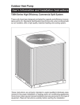
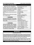
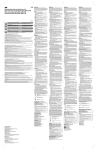
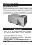
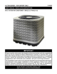
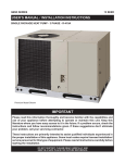
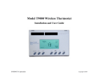
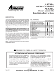
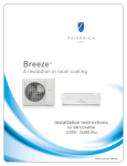
Outdoor Air Conditioner
USER’S INFORMATION AND INSTALLATION INSTRUCTIONS
S3BM-120G High Efficiency Commercial Split System
IMPORTANT
Read this owner information thoroughly and become familiar with the capabilities and use of your appliance before
attempting to operate or maintain this unit. Keep this literature where you have easy access to it in the future. If
a problem occurs, check the instructions and follow recommendations given. If these suggestions don’t eliminate
your problem, call your NORDYNE Servicing Contractor (Service PRO).
Any additions, changes, or conversions required for the appliance to satisfactorily meet the application needs must
be made by a qualified installer, service agency, or the gas supplier using factory specified and approved parts.
These instructions are primarily intended to assist qualified individuals experienced in the proper installation of
this appliance. Some local codes require licensed installation/service personnel for this type of equipment. Please
read all instructions carefully before starting the installation.
DO NOT DESTROY. PLEASE READ CAREFULLY AND KEEP IN A SAFE PLACE FOR FUTURE REFERENCE.
TABLE OF CONTENTS
USER’S INFORMATION
INSTALLER’S INFORMATION
SAFETY INFORMATION .............................................3
SAFETY INFORMATION .............................................4
Pressures Within The System .................................4
Labels, Tags and Precautions..................................4
Brazing Operations ..................................................4
OPERATING INSTRUCTIONS.....................................3
Cooling Operation....................................................3
Heating Operation ...................................................3
Operating the Indoor Blower Continuously ..............3
System Shutdown ....................................................3
SYSTEM MAINTENANCE ...........................................3
Regular Cleaning .....................................................3
Motor Lubrication .....................................................3
TROUBLESHOOTING .................................................3
GENERAL INFORMATION ..........................................4
Condensing Unit ......................................................4
Liquid and Suction Lines .........................................4
Field Connections for Electrical Supply ...................4
SITE PREPARATION ...................................................4
Unpacking the Equipment .......................................4
Inspect For Damage ................................................4
Preferred Location Of The Outdoor Unit ..................4
Facility Prerequisites................................................4
Minimum Circuit Ampacity .......................................5
Maximum Fuse/Circuit Breaker Size .......................5
INSTALLING THE OUTDOOR UNIT ............................5
Slab Mount ..............................................................5
Cantilever Mount......................................................5
Roof Mount ..............................................................5
INSTALLING THE INDOOR UNIT ................................5
CONNECTING REFRIGERANT TUBING ....................5
General ....................................................................5
Optional Equipment .................................................5
ELECTRICAL REQUIREMENTS .................................6
Pre-Electrical Checklist.................................................6
Wiring Diagram/Schematic ...........................................6
Supply Control Circuit Wiring ........................................6
Line Voltage ..................................................................6
Outdoor Unit Connections ............................................6
Disconnect Switch ........................................................6
Optional Equipment ......................................................6
Thermostat Connections ..............................................6
Grounding .....................................................................7
STARTUP AND CHECKOUT .......................................7
Air Filters ......................................................................7
Thermostat ...................................................................7
Outdoor Unit .................................................................7
System Cooling ............................................................7
Short Cycle Protection..................................................7
Heating .........................................................................7
Indoor Blower ...............................................................7
Adjustment Of Refrigerant Charge ...............................8
Refrigerant Charging Chart ..........................................8
Optional Equipment ......................................................8
ACCESSORIES ...........................................................8
Condensing Unit......................................................8
2
USER’S INFORMATION
SAFETY INFORMATION
Safety markings are used frequently throughout this
manual to designate a degree or level of seriousness and
should not be ignored. WARNING indicates a potentially
hazardous situation that if not avoided, could result in
personal injury or death. CAUTION indicates a potentially
hazardous situation that if not avoided, may result in minor
or moderate injury or property damage.
System Shutdown
Set the thermostat system switch (See Figure 1) to OFF
and the thermostat fan switch to AUTO. NOTE: The
system will not operate, regardless of the temperature
selector setting.
SYSTEM MAINTENANCE
CAUTION:
OPERATING INSTRUCTIONS
Cooling Operation
1. Set the thermostat system switch (Figure 1) to COOL
or AUTO and the thermostat fan switch to AUTO.
2. Set the thermostat temperature selector to the desired
temperature level. The outdoor fan(s), compressor(s),
and blower motor(s) will all cycle on and off to maintain
the indoor temperature at the desired cooling level.
Heating Operation
1. Set the thermostat system switch (Figure 1) to HEAT
or AUTO and the thermostat fan switch to AUTO.
2. Set the thermostat temperature selector to the desired
temperature level. The furnace/air handler blower
motor(s) will cycle on and off to maintain the indoor
temperature at the desired heating level.
Fan Mode
Fan Mode is typically used to circulate the indoor air to
equalize a temperature imbalance due to a solar load,
cooking, or fireplace operation. The continuous indoor
blower operation can be obtained with the system switch
set in any position, including OFF.
Set the thermostat’s fan switch to ON. The indoor blower
will start immediately, and run continuously until the fan
switch is reset to AUTO.
Temperature
Selector
Shut off all electrical power to the unit before
performing any maintenance or service on the
system. Failure to comply may result in personal
injury or death.
Proper maintenance is most important to achieve the best
performance from the appliance and should be performed
by a qualified service technician at least once a year.
Follow the maintenance schedule and the instructions
below for years of safe, trouble free operation.
Regular Cleaning
• Clean or replace the indoor air filter at the start of each
heating and cooling season, and when an accumulation
of dust and dirt is visible on the air filter.
• Remove any leaves and grass clippings from the coil
in the outdoor unit, being careful not to damage the
aluminum fins.
• Check for obstructions, such as twigs, sticks, etc.
Motor Lubrication
CAUTION:
Do not over-fill or oil a motor that is not factory
equipped with oil tubes. The compressor in
this unit is factory sealed and does not require
lubrication.
If the furnace/air handler blower motor(s) and the outdoor
unit fan motor(s) have oil tubes at the motor bearings,
apply 10 drops of SAE No. 20 motor oil to each oil tube
before each cooling season.
Thermometer
TROUBLESHOOTING
If the unit fails to operate, check the following:
• The thermostat is properly set. See Cooling Operation
for air conditioning or Heating Operation for furnace or
air handler.
• The unit disconnect fuses are in good condition and
the electrical power to the unit is turned on.
Fan Switch
System Switch
Figure 1. Typical Thermostat
3
INSTALLER’S INFORMATION
SAFETY INFORMATION
Safety markings are used frequently throughout this
manual to designate a degree or level of seriousness and
should not be ignored. WARNING indicates a potentially
hazardous situation that if not avoided, could result in
personal injury or death. CAUTION indicates a potentially
hazardous situation that if not avoided, may result in minor
or moderate injury or property damage.
WARNING:
Shut off all electrical power to the unit before
performing any maintenance or service on the
system. Failure to comply may result in personal
injury or death.
Pressures within the System
Split system air conditioning equipment contain liquid
and gaseous refrigerant under pressure. Installation
and servicing of this equipment should be performed
by qualified, trained personnel thoroughly familiar with
this type of equipment. Under no circumstances should
non-qualified personnel attempt to install and/or service
the equipment.
Labels, Tags, Precautions
When working with this equipment, follow all precautions
in the literature, on tags, and labels provided with
the equipment. Read and thoroughly understand
the instructions provided with the equipment prior to
performing the installation and operational checkout of
the equipment.
Brazing Operations
Installation of equipment may require brazing operations.
Safety codes must be complied with. Safety equipment
(e.g.; safety glasses, work gloves, fire extinguisher, etc.)
must be used when performing brazing operations.
GENERAL INFORMATION
This unit has been designed and tested for capacity and
efficiency in accordance with A.R.I. 340/360 Standards.
This unit will provide many years of safe and dependable
comfort, providing it is properly installed and maintained.
With regular maintenance, this unit will operate satisfactorily
year after year. Abuse, improper use, and/or improper
maintenance can shorten the life of the appliance and
create unsafe hazards.
To achieve optimum performance and minimize equipment
failure, it is recommended that periodic maintenance be
performed on this unit. The ability to properly perform
maintenance on this equipment requires certain
mechanical skills and tools.
4
Please consult your dealer for maintenance information
and availability of maintenance contracts. Please read all
instructions before installing the unit.
Condensing Unit
Each condensing unit is shipped with a refrigerant holding
charge adequate to maintain a positive pressure to keep
out contaminants. NOTE: Do not use any portion of the
charge for purging or leak testing.
Liquid and Suction Lines
Refrigerant grade copper tubing should be used when
installing the system. Refrigerant suction line tubing should
be fully insulated.
When condensing unit is matched with two air handlers
(two coils) or a dual circuit evaporator coil, refrigerant
tubing should be branched between both evaporator coils
or circuits using equal lengths of tubing to maintain equal
evaporator/circuit performance.
Field Connections for Electrical Power Supply
All wiring must comply with applicable local codes having
jurisdiction.The minimum size of electrical conductors and
circuit protection must be in compliance with information
listed on the outdoor unit data label.
SITE PREPARATION
Unpacking Equipment
Remove the cardboard carton and User’s Manual from the
equipment.Take care not to damage the tubing connections
when removing the carton.
Inspect for Damage
Inspect the equipment for damage prior to installing the
equipment at the job site. Ensure coil fins are straight
and, if necessary, comb fins to remove flattened and
bent fins.
Preferred Location of the Outdoor Unit
Conduct a survey of the job site to determine the
optimum location for mounting the outdoor unit. Overhead
obstructions, poorly ventilated areas, and areas subject
to accumulation of debris should be avoided. The outdoor
unit should be installed no closer than 18 inches from
the outside walls of the facility and in an area free from
overhead obstructions to ensure unrestricted airflow
through the outdoor unit.
Facility Prerequisites
Electrical power supplied to the unit must be adequate for
proper operation of the equipment. The system must be
wired and provided with circuit protection in accordance
with local building codes.
Minimum Circuit Ampacity
Electrical wiring to the equipment must be compatible and
in compliance with the minimum circuit ampacity listed
on the outdoor unit data label.
CONNECTING REFRIGERANT TUBING
BETWEEN THE INDOOR AND OUTDOOR
UNIT
Maximum Fuse/Circuit Breaker Size
Circuit protection for the outdoor unit must be compatible
with the maximum fuse/circuit breaker size listed on the
outdoor unit data label.
General
Once outdoor and indoor unit placement has been
determined, route refrigerant tubing between the
equipment in accordance with sound installation
practices.
INSTALLING THE OUTDOOR UNIT
• When connecting refrigerant linesets together, it is
recommended that dry nitrogen be flowing through the
joints during brazing.This will prevent internal oxidation
and scaling from occurring.
• Refrigerant tubing should be routed in a manner that
minimizes the length of tubing and the number of bends
in the tubing.
• Refrigerant tubing should be supported in a manner
that the tubing will not vibrate or abrade during system
operation.
• Tubing should be kept clean of foreign debris during
installation.
• Every effort should be made by the installer to ensure
that the field installed refrigerant containing components
of the system have been installed in accordance with
these instructions and sound installation practices to
insure reliable system operation and longevity.
• The maximum recommended interconnecting
refrigerant line length is 75 feet, and the vertical elevation
difference between the indoor and outdoor sections
should not exceed 20 feet.
• If precise forming of refrigerant lines is required, a
copper tubing bender is recommended. Avoid sharp
bends and contact of the refrigerant lines with metal
surfaces.
Slab Mount
The site selected for a slab mount installation requires
a stable foundation and one not subject to erosion. The
slab should be level and anchored (if necessary) prior to
placing the equipment on the slab.
Cantilever Mount
The cantilever mount should be designed with adequate
safety factor to support the weight of the equipment, and
for loads subjected to the mount during operation. Installed
equipment should be adequately secured to the cantilever
mount and levelled prior to operation of the equipment.
Roof Mount
WARNING:
To avoid the risk of property damage, personal
injury, or death, it is the rigger’s responsibility
to ensure that whatever means are used to hoist
the unit are safe and adequate:
• The lifting equipment must be adequate for
the load. Refer to Table 2 (page 9) for unit
weights.
• The unit must be lifted from the holes in the
base rails using cables or chains.
• Keep the unit in an upright position at all
times.
The method of mounting should be designed so as not to
overload roof structures or transmit noise to the interior
of the structure. Refrigerant and electrical lines should be
routed through suitably waterproofed openings to prevent
water leaking into the structure.
Optional Equipment
Optional equipment such as liquid line solenoid valves,
twinning kit, low ambient, etc., should be installed in
strict accordance with the manufacturer’s installation
instructions.
INSTALLING THE INDOOR UNIT
The indoor section should be installed before proceeding
with routing of refrigerant piping. Consult the installation
instructions of the indoor unit (i.e.: air handler, furnace,
etc.) for details regarding installation.
5
ELECTRICAL REQUIREMENTS
CAUTION:
Shut off all electrical power to the unit before
performing any maintenance or service on the
system. Failure to comply may result in personal
injury or death.
Pre-Electrical Checklist
√ Verify that the voltage, frequency and phase of the
supply source are the same as those specified on the
unit rating plate.
√ Verify that the service provided by the utility is
sufficient to handle the additional load imposed by this
equipment.
√ For minimum circuit ampacity and maximum overcurrent
protection, see the unit rating plate.
Wiring Diagram/Schematic
A wiring diagram/schematic is located on page 11 of this
manual and on the inside cover of the electrical box of
the outdoor unit.
IMPORTANT NOTE: The installer should become
familiar with the wiring diagram/schematic before
making any electrical connections to the outdoor
unit.
Supply Control Circuit Wiring
• The outdoor unit is equipped with a 24 VAC Class ll
transformer for low voltage circuit control. All wiring
must comply with applicable local codes having
jurisdiction.
• Units are shipped factory wired for 380 volt operation.
See unit data label for proper incoming field wiring.
• When using two air handlers, refer to twinning
instructions (707973) for proper low voltage control
wiring.
COPPER WIRE SIZE - AWG
(1% Voltage Drop)
Supply Wire Length - Feet
Supply Circuit
Ampacity
200
150
100
50
6
8
10
14
15
4
6
8
12
20
4
6
8
10
25
4
4
6
10
30
3
4
6
8
35
3
4
6
8
40
2
3
4
6
45
2
3
4
6
50
2
3
4
6
55
1
2
3
4
60
NOTE: Wire size based on N.E.C. for 60° type copper conductors.
Table 1. Copper Wire Size
6
Line Voltage
• Electrical power wiring must be made in accordance
with all applicable local codes and ordinances.
• Provide power supply for the unit in accordance with
the unit wiring diagram, and the unit rating plate.
• Connect the line-voltage leads to the terminals on the
contactor inside the control compartment.
• Use only copper wire for the line voltage power supply
to this unit. Use proper code agency listed conduit and
a conduit connector for connecting the supply wires to
the unit.
CAUTION:
Label all wires prior to disconnection when
servicing controls. Wiring errors can cause
improper and dangerous operation.Verify proper
operation after servicing.
• If any of the original wire as supplied with the unit must
be replaced, it must be replaced with material of the
same gauge and temperature rating.
• See the unit wiring label for proper high and low voltage
wiring. Make all electrical connections in accordance
with all applicable codes and ordinances.
• Use a separate branch electrical circuit for this unit. A
means of electrical disconnect must be located within
sight of and readily accessible to the unit.
• Overcurrent protection must be provided at the branch
circuit distribution panel and sized as shown on the unit
rating label and according to applicable local codes.
Outdoor Unit Connections
The outdoor unit requires both power and control circuit
electrical connections. Refer to the wiring diagram (Figure
3, page 11) for identification and location of outdoor unit
field wiring interfaces.
Disconnect Switch
An electrically compatible disconnect switch must be within
line of sight of the outdoor unit.This switch shall be capable
of electrically de-energizing the outdoor unit.
Optional Equipment
• Optional equipment requiring connection to the power
or control circuits must be wired in strict accordance
with applicable local codes having jurisdiction, and the
installation instructions provided with the equipment.
• Optional Equipment (e.g.: liquid line solenoid valves,
twinning kit, low ambient, etc.) should be installed in
strict accordance with the manufacturer’s installation
instructions.
Thermostat Connections
Thermostat connections should be made in accordance
with the instructions supplied with the thermostat, and with
the instructions supplied with the indoor equipment.
Grounding
CAUTION:
The unit cabinet must have an uninterrupted or
unbroken electrical ground to minimize personal
injury if an electrical fault should occur. This
ground may consist of electrical wire or approved
conduit when installed in accordance with
national or local codes. Do not use gas piping
as an electrical ground!
• This unit must be electrically grounded in accordance
with local codes.
• Proper grounding is accomplished by using the
grounding lug provided in the control box.
STARTUP AND CHECKOUT
CAUTION:
Shut off all electrical power to the unit before
performing any maintenance or service on the
system. Failure to comply may result in personal
injury or death.
Air Filters
Ensure air filters are clean and in place prior to operating
the equipment.
Thermostat
Set the room thermostat function switch to OFF, fan
switch to AUTO, and move temperature setpoint to its
highest setting.
Prior to applying electrical power to the outdoor unit, verify
that the unit has been properly and securely grounded,
and that power supply connections have been made at
both the facility power interface and outdoor unit.
Outdoor Unit
Verify the outdoor coil and top of the unit are free from
obstructions and debris, and all equipment access/control
panels are in place. Using extreme caution, apply power
to the unit and inspect the wiring for evidence of open,
shorted, and/or improperly wired circuits.
System Cooling
1. Set the thermostat system switch to COOL and the
fan switch to AUTO.
2. Lower the thermostat temperature switch below room
temperature and verify that the refrigerant pressures
are in order.
3. Listen for any unusual noises. Locate the source and
correct as needed.
4. Allow the unit to run. After several minutes, set the
temperature selector above room temperature.
5. Verify that the fan, blower, and compressor cycle off
with the thermostat.
Short Cycle Protection
1. Set the system in COOLING mode. Note the setpoint
temperature setting of the thermostat, and gradually
raise the setpoint temperature until the outdoor unit
and indoor blower de-energize.
2. Immediately lower the setpoint temperature of the
thermostat to its original setting.
3. Verify that the indoor blower is energized and that the
outdoor unit remains de-energized.
4. Wait 5 minutes and verify the outdoor unit energizes
and that the temperature of the air supplied to the
facility is cooler than ambient temperature.
Heating
1. If equipped with heating equipment, lower the
thermostat setpoint temperature to the lowest
obtainable setting.
2. Set the thermostat function switch to HEATING. The
indoor blower and outdoor unit should stop running.
3. Increase the setpoint temperature of the thermostat
to the maximum setting.
4. Verify that the heating equipment has been energized
(i.e., fossil fuel burner operating, etc.) and that the
indoor blower energizes after a short period of time.
Feel the air being circulated by the indoor blower and
verify that it is warmer than ambient temperature.
5. Listen for any unusual noises. If present, locate and
determine the source of the noise and correct as
necessary.
Indoor Blower
1. Set the thermostat fan switch to ON.
2. Verify that the indoor blower is operating and that
airflow is not restricted.
3. Set the fan switch back to AUTO.
WARNING:
If this unit is equipped with crankcase heaters,
Allow 24 hrs for heating of the refrigerant
compressor crankcase prior to start up. Failure to
comply may result in damage or cause premature
failure of the system.
NOTE: If refrigerant pressures are abnormal and the
condenser fan is rotating backwards, shut off main
power to the unit and switch any two field wires at the
disconnect. DO NOT alter unit wiring.
7
Adjustment of Refrigerant Charge:
CAUTION:
Split system air conditioning equipment contains
liquid and gaseous refrigerant under pressure.
Adjustment of refrigerant charge should only
be attempted by qualified, trained personnel
thoroughly familiar with the equipment.
Under no circumstances should the homeowner
attempt to install and/or service this equipment.
Failure to comply with this warning could result in
equipment damage, personal injury, or death.
NOTE: The following Refrigerant Charging Chart is only
applicable to matched assembly utilizing two 5.0 ton air
handlers (sku 904374D), with the blower set on high
speed. It is recommended this matched system only be
operated with indoor blower settings on high speed. If
medium airflow setting is selected, special precautions
should be taken to prevent possible coil freeze up for low
outdoor ambient and low indoor load operation.
Assemblies of indoor coils and outdoor units not listed
are not recommended and deviations from rated airflows
or non-listed equipment combinations may require
modifications to the expansion device(s) and refrigerant
charging procedures for proper and efficient system
operation.
Check the system for leaks, including the lineset
and the brazed joints. Pressurize the system with
nitrogen and apply a soap and water solution
to each joint or union with a small paintbrush.
NOTE: If bubbling is observed, the connection is not
adequately sealed.
MODEL NUMBER
ORIFICE SIZE
10 Ton
0.093
Table 1. Preliminary Orifice Usage
9 E.E.R. Commercial Air Conditioner
Refrigerant Charging Chart
Refer to Refrigerant Charging Chart Figure 2, page 10)
for correct system charging, and the Orifice Usage Chart
(Table 1) for correct restrictor sizes.
Optional Equipment
A functional checkout should be performed in accordance
with the checkout procedures supplied with the
equipment.
ACCESSORIES
Condensing Unit
Low Ambient Kit 913549A- Maintains system pressures
during low ambient conditions.
8
PHYSICAL AND ELECTRICAL SPECIFICATIONS / OUTDOOR UNITS
9 E.E.R. - High Efficiency (380 Volt) - Three Phase (50Hz)
Performance Data
Gross Cooling Capacity
122,500
NET Cooling Capacity
117,000
Rated Airflow (CFM)
3,600
Efficiency-E.E.R. (Btu/Watt)
9.00
Volts-Phase-Hz
380-420/3/50
Voltage Range (Min-Max)
Electrical Data
Total Amps
20.1
Min. Circuit Ampacity
24.5
Delay Fuse max. (1)
40
Wire Size/Max Length (AWG 60° C Cu)
10
Wire Size/Max Length (AWG 75° C Cu)
10
Coil
Fan Motor
Area
31.94
Rows-FPI
1-22
Tube Diameter
3/8 O.D.
Volts-Phase-Hz
380-420/3/50
Qty
1
Horsepower
1
Full Load LRA
Component Data
360-440
Fan Blade
Diameter/Pitch/# Blades
RPM/CFM (Max-Total)
Voltage-Phase-Hz
Qty/Type
Model
Compressor Data
30-19-3
900/8,000
380-420/3/50
1/Scroll
ZR144KC
RLA
17.7
LRA
118
Stages/Percent
Crankcase Heater Qty./Type
Refrigerant Suction Line-Length/O.D.
(Liquid Line all lengths - 5/8” O.D.)
Circuits (Qty) -1
2.4
1/100
1/Band
0 - 15 ft.
1 1/8”
16 - 25 ft.
1 1/8”
26 - 75 ft.
1 3/8” (3)
Refrigerant Charge
Holding
76
R-22 Ounces
Total System with
25’ Lineset (2)
392
Weight Approximate (lbs.)
Net:
341
Ship:
378
NOTES:
Net capacity includes indoor blower motor heat deduction.
Gross capacity does not include indoor blower motor heat deduction.
(1) HACR Type circuit breakers may be used.
(2) Add 9.0 oz. of refrigerant per 5ft. of additional lineset.
(3) Requires 1-3/8” to 1-1/8” reducer from unit to line.
Table 2. S3BM-120G Electrical Specifications
9
Figure 2. S3BM-120G Charging Chart
10
Liquid Pressure (PSIG)
150
160
170
180
190
200
210
220
230
250
240
260
270
280
290
300
310
320
330
340
65
70
75
80
85
95
100
105
110
115
120
125
130
Add refrigerant when below curve
Liquid Temperature (Deg. F)
90
Remove refrigerant when above curve
S3BM-120G (380V/3 Ph./50Hz.) Charging Chart
with Two - 5.0 Ton Air Handlers - High Speed
135
140
Figure 3. S3BM-120G Wiring Diagram
11
L1
L3
L2
Y
ASCT
T2
T3
CCH
T1
COMPRESSOR
CC
24V FOR INDOOR
CONTROL CIRCUIT
LOW
PRESSURE
SWITCH
TRANSFORMER
L2
HIGH
PRESSURE
SWITCH
ASCT
OUTDOOR FAN
MOTOR
CC
ISOLATED
T-STAT
CONTACT
R
L1
CC
CC
L3
C
LEGEND:
FIELD WIRING
LOW VOLTAGE
HIGH VOLTAGE
T1
T2
L2
T1
L1
L3
T3
3 Phase / 50 Hz.
RED
R
Y C
¢710878Q¤
BLACK
TRANSFORMER
(PRIMARY)
24V
GREEN
BLACK
ANTI-SHORTCYCLE TIMER
T3 T1 T2
0309
710878A
(Replaces 7108780)
BLACK
BLACK
HIGH PRESSURE
SWITCH
YELLOW
GREEN
BROWN
LOW PRESSURE
SWITCH
BROWN
RED
L2
OUTDOOR FAN
MOTOR
L3
L1
1. Couper le courant avant de faire letretien.
2. Employez uniqement des conducteurs en cuivre.
BLACK
YELLOW
380 Volt
GRND L1
L2
L3
3-PHASE SUPPLY
VOLTAGE
BLACK
BLACK
CONTACTOR
BLACK
RED
YELLOW
GROUNDING LUG
COMPRESSOR
T2
T3
CCH
NOTES:
1. Disconnect all power before servicing.
2. For supply connections use copper conductors only.
3. Furnace/Air Handler w/factory equipped 24V control circuit transformers, should be
modified/rewired to ONLY use 24V transformer from outdoor section. See Installation
Instructions for typical modifications.
4. For replacement wires use conductors suitable for 105° C.
5. For ampacities and overcurrent protection, see unit rating plate.
Split System Air Conditioner (Outdoor Section)
BLACK
WIRING DIAGRAM
WHITE
¢709008'¤
O’Fallon, MO
709008A
709008A (Replaces 7090080)
Specifications and illustrations subject to change
without notice or incurring obligations.
Printed in U.S.A. (03/09)