1
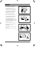
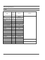
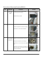
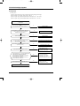
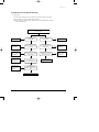
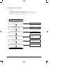
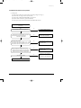
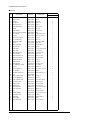
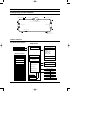
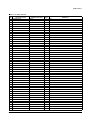
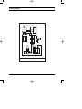
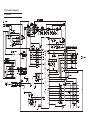
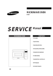
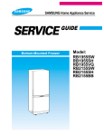
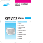
DB98_04511A(2)-CO
2/18/03 4:08 PM
Page 3
ROOM AIR CONDITIONER
SP05A10
SERVICE
AIR CONDITIONER
Manual
CONTENTS
11. Precautions
12. Product Specifications
13. Installation and Operating
Instructions
14. Disassembly and Reassembly
15. Troubleshooting
16. Exploded Views and Parts List
17. Block Diagram
18. PCB Diagram
19. Wiring Diagram
10. Schematic Diagram
DB98_04511A(2)-1
2/18/03 4:09 PM
Page 1-1
1. Precautions
1. Warning: Prior to repair, disconnect the
power cord from the circuit breaker.
2. Use proper parts: Use only exact
replacement parts. (Also, we recommend
replacing parts rather than repairing them.)
3. Use the proper tools: Use the proper tools
and test equipment, and know how to use
equipment may cause problems laterintermittent contact, for example.
4. Power Cord: Prior to repair, check the
power cord and replace it if necessary.
Fig. 1-1 Avoid Dangerous Contact
5. Avoid using an extension cord, and avoid
tapping into a power cord. This practice
may result in malfunction or fire.
6. After completing repairs and reassembly,
check the insulation resistance.
Procedure: Prior to applying power, measure
the resistance between the power cord and the
ground terminal. The resistance must be
greater than 30 megaohms.
7. Make sure that the grounds are adequate.
Fig. 1-2 No Tapping and No Extension Cords
8. Make sure that the installation conditions
are satisfactory.
Relocate the unit if necessary.
9. Keep children away from the unit while it is
being repaired.
10. Be sure to clean the unit and its surrounding
area.
Fig. 1-3 No Kids Nearby!
Fig. 1-4 Clean the Unit
FRIEDRICH AIR CONDITIONING CO.
1-1
2.Product Specifications
2-1 Table
Item
Unit of
Measure
Type
Dimension:
SP05A10
REMARK
WINDOW
mm
424×310×326
Voltage
Volt
115
Phase
-
SINGLE
Frequency
Hz
60
Operation Current
A
4.6
Power Consumption
W
500
FREON
R22
g
300
BTU/h
5400
BTU/h.W
10.8
Net Weight
Kg
18.5
Condenser
Row
2×15
Condenser Fan
Type
Propeller Fan
Evaporator
Row
2×10
Evaporator Fan
Type
Blower
Fan Motor
MODEL
YGN50-6K(E)
Compressor(Rotary)
MODEL
39A050HS1KA
-
MRA12145-12008
Compressor Capacitor
μF/VAC
35/270
Two Capacitor combined to be the one
Fan Motor Capacitor
μF/VAC
3.5/270
with below spec: 35/3.5µF
RPM
1060/1010/960
-
THERMISTOR
(Width×Height×Depth)
Refrigerant Type
Refrigerant Change
Capacity
EER
Overload Protect
Fan Speed
Thermo Control
FRIEDRICH AIR CONDITIONING CO.
270VAC
2-1
DB98_04511A(2)-1
2/18/03 4:09 PM
Page 2-4
MEMO
2-3
FRIEDRICH AIR CONDITIONING CO.
2-2 Dimensions
2-2-1 Main Unit
326
(Unit : mm)
Front view
310
310
Side view
424
2-2-2 Remote Control
Remote control
transmission indicator
Operating mode
(
Cool,
Dry,
Mode selection button
(Cool, Fan, Dry)
Fan)
Temperature setting
Sleep mode
Temperature adjustment
buttons
Sleep timer setting button
Energy Saving mode
Fan speed adjustment
button
Fan speed
On Timer setting
Off Timer setting
Energy Saving button
Timer setting button
Timer Set/Cancel button
Battery discharge indicator
On/Off button
2-4
FRIEDRICH AIR CONDITIONING CO.
DB98_04511A(2)-1
2/18/03 4:09 PM
Page 3-1
3. Installation and Operating Instructions
3-1 Installation
3-1-1 Selecting Area for Installation
1. Make sure that you install the unit in an area
providing good ventilation. The air conditioner
must not be blocked by any obstacle affecting the
air flow near the air inlet and air outlet.
2.
Make sure that you install the unit in an area that
allow good air handling. The installation area
must be able to endure vibration from the unit.
3.
Make sure that you install the unit away from
heat or vapor.
4.
Make sure that you install the unit in an area
which is cool and has adequate space.
5.
Make sure that you install the unit in an area
away from TVs, audio units, cordless phones,
fluorescent lighting fixtures and other electrical
appliances (obtain a clearance of at least one
meter).
6.
Make sure that you install the unit in an area
which provides easy drainage for condensed
water.
7.
Make sure that you install the unit in an area not
exposed to rain or direct sunlight.
(Install a separate sunblind if exposed to direct
sunlight.)
8.
Make sure that you install the unit in an area
allowing good air movement. Do not install it in
a space that would cause noise amplification of
noise.
9. Fix the unit firmly if mounted in a high place.
Caution:
Do not use the air conditioner in the following environments : greasy areas (including areas near
machines), or marine areas. Contact your local dealer for advice.
FRIEDRICH AIR CONDITIONING CO.
3-1
DB98_04511A(2)-1
2/18/03 4:09 PM
Page 3-2
3-2 Function Description
3-2-1 Cooling operation mode
The compressor is turned on and off according to the ambient temperature and set temperature.
1) Compressor on and off control
• Compressor on and off control according to the ambient temperature
* The compressor is turned off when "ambient temperature = set temperature
* The compressor is turned on when "ambient temperature = set temperature +1˚C"
2) Default value after power reset ➔ set temperature = 75˚F
Fan speed = High
3) Set temperature indicating (setting) range : 1˚F interval from 64˚F to 86˚F.
3-2-2 Fan operation mode
1) If "Fan operation mode" signal is received from remocon or panel.
➔ the compressor is immediately turned off and only fan motor is operated at set blowing speed.
➔ it changes such as "High ➔ Med ➔ Low ➔ High"( if Fan speed is selected).
2) The initial Fan motor speed is set to "High".
3) The set temperature can not be indicated and set.
3-2-3 Energy saver operation mode
* If the compressor turn off at the cooling operation, the fan motor turn off after operation during the fixation
time only, and operation that energy saver by turn off the fixation time only, and operation that energy saver
by turn off the motor continuously before the condition of the compressor on.
* The fan motor is not operated at flow wind operation.
* Energy saver operation specification at the cooling operation.
1) Fan motor control in compressor on : operate with setting wind speed
2) Fan motor control in compressor off : After compressor off, the fan motor is operated breeze for 2 minutes
and then it turn off.
3) After the fan motor off, the compressor and fan motor is operated normally when the compressor on.
3-2
FRIEDRICH AIR CONDITIONING CO.
DB98_04511A(2)-1
2/18/03 4:09 PM
Page 1
Installation and Operating Instructions
3-2-4 Sleep operation mode
1) Enable to sleep operation only when cooling operation.
2) First, 7-SEG LED DISPLAY "SLEEP" while 15 second, Second, 7-SEG LED DISPLAY "8Hr"
And, automatically SET OFF after operated while 8 Hour
3) If sleep operation, setting Temperature rise 1˚C after 1 Hour
4) ON TIMER operation, not operation, ENERGY SAVER operation, not sleep operation.
3-2-5 Dry operation mode
If the atmosphere in the room is very humid or damp,use this operation mode. It can remove excess humidity
without lowering the room temperature too much.
1) The quantity of air is adjusted automatically.
3-2-6 LED display indication in case of error detection
ERROR OPERATION
7-SEG
LED DISPLAY
ROOM THERMISTOR
(OPEN or SHORT)
E1 displayed
1) Set operation in case of error occurrence.
• Malfunction of each temperature sensor (open, short)
- Error mode display, warning sound.
- The operation status is off.
FRIEDRICH AIR CONDITIONING CO.
3-3
DB98_04511A(2)-1
2/18/03 4:09 PM
Page 2
MEMO
3-4
FRIEDRICH AIR CONDITIONING CO.
DB98_04511A(2)-1
2/18/03 4:09 PM
Page 3
4. Disassembly and Reassembly
4-1 Compressor Replacement Flow Chart
Locate cause of defect
Release refrigerant
Disconnect electrical wiring
from compressor
Cut refrigerant lines
from compressor
Plug disconnected lines
Replace compressor
Inspect electrical
wiring for defects,
and terminals for
correct and secure
connections
Solder discharge line
Solder suction line
Use nitrogen gas
Perform soldering function
Y
Problem?
Fill system with
nitrogen gas
N
Check for leakage
Corrective action
Leakage?
Y
Check refrigerant oil level
N
Release nitrogen gas?
Y
Low oil level?
N
Evacuate system
Add oil as necessary
Recharge system
Pinch and braze filling tube
FRIEDRICH AIR CONDITIONING CO.
4-1
DB98_04511A(2)-1
2/18/03 4:09 PM
Page 4
4-2 Checking the oil
Fill the transparent container with 10cc of oil, and then conduct the test.
4-2-1 Oil quality
Oil Condition
Condition of
Refrigerant Cycle
Color
Odor
Normal
Straw Yellow
No Odor
Return with the system
Over-heated
Brown Color
-
Change the oil
Compressor Damage
Dark Brown
Pungent oil
Change the oil
Remarks
4-2-2 Replacing and refilling the refrigerant oil
1. Change the compressor - DO NOT recharge the oil as the compressor itself is
already charged.
2. Change the condenser .... add 50cc
3. Change the evaporator .... add 50cc
4. When the refrigerant is replaced .... add 30cc oil.
5. After vacuum is completed, the oil is filled through the high pressure side.
6. In the event of a refrigerant leak, generally it is not necessary to add oil.
(Unless the oil has leaked significantly.)
4-2
FRIEDRICH AIR CONDITIONING CO.
4-3.Disassembly and Reassembly Procedure(SP05A10)
Stop operating the air conditioner, and pull out the power cord before repair.
No.
Part Name
Procedures
1
Ass’y Grille
1.Pull the Grille air inlet and Guard air filter out.
Remarks
2.Remove the screw on the panel front.
3.Hold the lower part of panel with two hands
while pressing down on both sides of the lower
part of the cabinet, pull it forward by about
30mm,and then lift it up carefully for removal.
2
Ass’y Cabinet
1.Remove all screws on the both side of the
cabinet .
2.Take the cabinet upward.
3
Ass’y Control
1.Remove the earth screw fixed on the base.
2.Remove 3 screws fixed on the partition.
3.Remove the screw fixed for the power cord.
4.Un-connect the motor wire and comp lead
wire, then take out the control box upward.
(The picture maybe have a little
different from actual product)
FRIEDRICH AIR CONDITIONING CO.
4-3
Disassembly and Reassembly Procedure(SP05A10)
No.
Part Name
4
CASE EVAP
UP & ASSY
EVAP
Procedures
Remarks
1.Take the case evap up forward carefully.
(tear all the seal on it before )
2.Pull the frame up upward.
5
Blower
1.Remove all screws on the evaporator.
2.Pull the evaporator from frame low carefully.
3.Remove the nut and remove the Blower.
6
Case Cond &
Fan Propeller
& Motor Fan
1.Remove 2 screws on the rear side of the
base pan, and all screws fixed on case cond.
2.Pull up the condenser from the base pan.
3.Remove the nut and remove the Propeller
fan.
4.Remove the screw fixed on the partition and
earth screw fixed on the base pan, then take
out the motor backward.
4-4
FRIEDRICH AIR CONDITIONING CO.
DB98_04511A(2)-2
2/18/03 4:12 PM
Page 5-1
5. Troubleshooting
Check the basic checkpoints first to determine whether it is machine trouble or a problem
in the operation method. When it is not related to the basic checkpoints, perform checking
in accordance with the procedures of troubleshooting by symptom.
5-1 Basic Checkpoints for Troubleshooting
1) Is the voltage of the power source appropriate ?
(1) It should be within the rating voltage ±10% range.
(2) The air conditioner may not operate properly when the voltage is out of this range.
2) Is the connection with the fan motor, compressor wire, and starting condenser
appropriately made ?
3) The symptoms listed in the table below are not indicative of machine trouble.
Symptom
Cause and check
No operation
• Check whether there is power failure or the power plug is pulled out.
• Check whether the unit is stopped as a result of completion
of the sleep time.
• Pull out the power plug for ten seconds, and then insert it again.
Air flows, but
no cooling
• Check whether the Air filter is clogged with dust or is dirty.
• Check whether the desired temperature is too high. Set the desired
temperature to a lower level than the current temperature.
• Check whether it is in "FAN" mode.
The remocon does
not operate
• Check whether battery is completely depleted.
• Check whether the battery is properly inserted.
• Check whether the receiving window of the remocon for the assembly
main PCB is blinded.
• Check whether the remocon is affected by jamming due to a neon sign.
No temperature
setting
• Check whether the unit is in "FAN" mode.
(In "FAN" mode, only the current temperature is displayed, and the
desired temperature is not set.)
❈ Checking and Display of Fault Area
ERROR OPERATION
ERROR OPERATION
ROOM THERMISTOR (OPEN OR SHORT)
E1 displayed
FRIEDRICH AIR CONDITIONING CO.
5-1
DB98_04511A(2)-2
2/18/03 4:12 PM
Page 5-2
5-2 Troubleshooting by Symptom
5-2-1 No power
1) Check points
(1) Is the voltage of the power source normal ? (the rating voltage ±10% range.)
(2) Is the electric wire in good contact ?(CN 71, RY 71)
(3) Is the output voltage of the IC01(KA 7812) normal ?(DC 11.5V ~ DC 12.5V)
(4) Is the output voltage of the IC02(KA 7805) normal ?(DC 4.5V ~ DC 5.5V)
Turn off the power, and then turn it on again five
seconds later.
Y
Dose the buzzer sound, when the power on?
Normal operation.
N
Check whether the "COOLING ICON" LED lamp is
on, and the operation starts when pressing the
ON/OFF button of the remocon.
Y
Normal operation.
N
Y
Is the F701(3.15A) fuse blown?
Replace the fuse.
N
Is the primary voltage of the transformer normal?
(the rating voltage ±10% range.)
N
Check the power cord and electric wire.
Y
Is the secondary voltage of the transformer normal?
(AC 13V ~ AC 17V)
N
Check and replace the trans.
Y
N
Is the rectifier diode bridge(BD61) normal?
Y
- Is the voltage of DC 17V ~ DC 23V applied at both
ends of the C101 electrolytic condenser?
- Is the voltage of DC 12V applied at both ends of
the C102 electrolytic condenser?
- Is the voltage of DC 5V applied at both ends of
the C103 electrolytic condenser?
N
• Check the BD61 for cold
soldering.
• Replace the rectifier diode
• Check both ends of the C101 for
short and cold soldering.
• Check the +12V for a short.
• Check the +5V for a short.
• Check and replace the C101~104.
Y
N
Are the IC01(KA7812) or IC02(KA7805) normal?
Y
• Check the IC01 or IC02 for cold
soldering and a short.
• Replace the IC01 or IC02.
Replace the assembly main PCB.
5-2
FRIEDRICH AIR CONDITIONING CO.
DB98_04511A(2)-2
2/18/03 4:12 PM
Page 5-3
Troubleshooting
5-2-2 When the Touch Key pad and Led Display
1) Check points
(1) Is the voltage of the power source normal ? (the rating voltage ±10% range.)
(2) Is the electric wire in good contact ?(CN71, RY71)
(3) Is the connection of the assembly main PCB, and TOUCH KEY PAD in good
contact? (SW01-SW05)
Turn off the power, and then turn it on again
five seconds later.
N
Normal operation
When the LED display is
not operated.
Y
Check the micom
(IC05) for a short,
and replace it.
N
Is the voltage of the micom
(IC05) No.1, 2, 38~43 port a
square wave?
Y
Check the micom
(IC05) for a short,
and replace it.
N
Is the voltage of the micom
(IC05) No.3, 4, 10, 11, 44 port
a square wave?
Y
Check the Q901~
Q905 for a short,
and replace it.
N
Is the voltage of the
Q901 ~ Q905 square wave?
When the membrane key is
not operated.
N
Normal operation
Y
Is the voltage of the
micom (IC05) No.13, 14 port
a square wave?
N
Check the micom
(IC05) for a short,
and replace it.
N
Check the micom
(IC05) for a short,
and replace it.
Y
Is the voltage of the micom
(IC05) No.3, 4, 10, 11, 44
port a square wave?
Y
Replace the membrane
key pad.
Y
Check the IC06
for a short, and
replace it.
N
Is the voltage of the
IC06 No. 10~16 a square
value?
Y
Replace the membrane key pad
FRIEDRICH AIR CONDITIONING CO.
5-3
DB98_04511A(2)-2
2/18/03 4:12 PM
Page 5-4
Troubleshooting
5-2-3 When the remocon is not operated
1) Check points
(1) Is the voltage of the power source normal ? (the rating voltage ±10% range. )
(2) Is the electric wire in good contact ? (CN71, RY71)
(3) Is the assembly main PCB in good contact with the TOUCH KEY PAD(SW01-SW05)
(4) Is the battery voltage of the remocon above DC 2.7V?
Turn off the power, and then turn it on
again five seconds later.
N
Go to the clause "No power".
Dose the Buzzer sound, when the power on?
Y
Check whether the "COOLING ICON" LED lamp is on
and th operation starts when pressing the
on/off button of the remocon.
Y
The remocon is normally operated.
N
Is the battery voltage of the remocon above
DC 2.7V?
N
Replace the battery.
Y
N
• Check the X-TAL for cold soldering
and a short.
• Replace relevant components.
N
• Check the micom(ICT1) Q1, and
Q2 for cold soldering and a short.
• Replace relevant components.
Does the X-TAL(RJ 455JB) oscillate normally?
Y
Is the collector voltage of the remocon Q1, Q2
a square wave?
Y
Is the input voltage of the micom(IC05) No.15
pin of the assembly main PCB a aquare wave?
N
• Check the R415 components.
• Check the assembly main PCB
micom(IC05).
Y
Replace the assembly main PCB.
5-4
FRIEDRICH AIR CONDITIONING CO.
DB98_04511A(2)-2
2/18/03 4:12 PM
Page 5-5
Troubleshooting
5-2-4 When the compressor is not operated
1) Check points
(1) Is the voltage of the power source normal ? (the rating voltage ±10% range. )
(2) Is the desired temperature lower than the indoor temperature in the “COOL” mode?
(Compressor stopped)
(3) Is the starting condenser in good contact?
(4) Is the electric wire in good contact ? (CN71, RY71)
(5) Is the output voltage of the IC01(KA7812) and IC02(KA7805) normal ?
Turn off the power, and then turn it on again five
seconds later.
N
Go to the clause "No power".
Dose the Buzzer sound, when the power on?
Y
Check whether the "COOLING ICON" LED lamp is on
and the operation starts when pressing the on/off
button of the remocon.
N
• Go to the clause "when he remocon
does not operate".
Y
Check whether the compressor is activated in three
minutes after turning on the power with the "CoolING
ICON" LED lamp being switched on when selecting the
cool mode of the remocon.
Y
Normal operation.
N
Is the IC03 output normal?
- When the compressor is on, IC03
No. 13 pin → Low.
N
• Check the IC03 for short and cold
soldering.
• Replace the IC03.
N
• Check the relay coil resistance.
(resistance : About 150Ω±20Ω)
• Replace the relay.
Y
Does the relay(RY71) operate normally?
- When the compressor is ON, the RY71 should operate.
Y
N
Is the compressor normal?
Y
• Check the operation of the O.L.P,
and replace it if necessary.
• Check the compressor
resistance.(0Ω : short, ∞Ω : open)
Replace the compressor.
FRIEDRICH AIR CONDITIONING CO.
5-5
DB98_04511A(2)-2
2/18/03 4:12 PM
Page 5-7
Troubleshooting
5-2-5 When the fan motor does not operated
1) Check points
(1) Is the voltage of the power source normal ? (the rating voltage ±10% range. )
(2) Is the electric wire in good contact ?(CN71, RY71)
(3) Is the starting condenser(FAN MOTOR) in good contact?
(4) Is the fan motor connector in good contact?(CN73)
(5) Is the output voltage of the IC01(KA7812) and IC02(KA7805) normal ?
Turn off the power, and then turn it on again five
seconds later.
N
Go to the clause "No power".
Dose the buzzer sound, when the power on?
Y
Check whether the "COOLING ICON" LED lamp is on
and the operation starts when pressing the
on/off button of the remocon.
N
• Go to the clause of "when the
remocon does not operated".
Y
Is the IC03 output normal?
- When the fan motor is High, IC03 No. 12 pin → Low.
- When the fan motor is Med, IC03 NO. 14 pin → LOW.
- When the fan motor is Low, IC03 No. 15 pin →Low.
N
• Check the IC03 for a short and cold
soldering.
• Replace the IC03.
N
• Check the relay coil resistance.
(Normal: About 400Ω)
• Replace the relay.
Y
Does the relay(RY 72, 73,74) operate normally?
- When the fan motor is High, RY74 should operate.
- When the fan motor is Med, RY73 should operate.
- When the fan motor is Low, RY72 should operate.
Y
Is the fan motor normal?
N
• Check the fan motor resistance.
(0Ω : short, ∞Ω : open)
• Check the fan motor thermal fuse?
Y
Replace the fan motor.
FRIEDRICH AIR CONDITIONING CO.
5-7
FRIEDRICH AIR CONDITIONING CO.
1-4
1-1
1-3
3
1-2
5
4
8
30
29-1
29-5
6
29-7
29-6
9
7
10
29-3
29-8
11
2
29-2
29-4
29-9
12
29
14
21
28
25
13
31
15
16
27
26
22
24
23
33
17
18
20
32
19
2/18/03 4:12 PM
1
SP05A10
EXPLODED VIEW
DB98_04511A(2)-2
Page 6-1
6. Exploded View and Parts List
6-1 Main unit
6-1
Exploded View and Parts List
■Part List
No
1
Description
Code No.
Specification
Q'TY
SP05A10
ASSY PANEL FRONT
DB92-00393B
ASSY,TOP,SEA
1
1-1
PANEL FRONT
DB64-00680A
HIPS,T2
1
1-2
BLADE V
DB66-00367A
HIPS,T2.0
4
1-3
LINK BLADE
DB66-00368A
PP,L82,T1.3
2
1-4
GRILLE AIR INLET
DB64-00681B
HIPS,T2
1
2
CASE CONTROL UP
DB61-00933A
SGCC-M,T0.7
1
3
FILTER
DB63-00600A
HIPS,T2.5
1
4
EVAPORATOR
DB96-01972A
2R×10S,FP1.3
1
5
ASSY-PLATE EVAP CASING
DB90-00898A
ASSY
1
6
NUT-FRANGE
DB60-30004A
2C M6 SM20C NTR
1
7
BLOWER
DB67-00099A
ABS,-,OK_TOP-P/J
1
8
ASSY-EVAP CASE UP
DB90-00944A
25FO-PS
1
9
PLATE-PARTITION
DB70-00219A
ABS,-,T2.5
1
10
INSULATION-TUBE
DB72-50178A
T30,W36,L34,NBR
1
11
MOTOR
DB31-00035K
YGN50-6K
1
12
FAN-PROPELLER
DB67-00014A
ABS,290,OK-PJT
1
13
NUT-FRANGE
DB60-30020A
M6,LEFT
1
14
CASE COND
DB61-00932A
复合PP,T2,W378,L308
1
15
ASSY-COND
DB96-02044A
2R×15S,FP1.5
1
16
ASSY SHUTTER-LF
DB92-00336A
PVC,SC-94445R
1
17
ASSY CABINET
DB90-00912A
Y-PJT,TOP
1
18
SHUTTER-ANGLE UP
DB64-00518A
SECC-P,T1,W8
1
19
ASSY SHUTTER-RH
DB92-00337A
PVC,SC-94445R
1
20
TUBE DISCHARGE
DB62-01349A
C1220T-0
1
21
TUBE SUCTION
DB62-01314A
C1220T-0
22
COMPRESSOR
39A050HS1KA 115V 60Hz 1Ph
1
23
NUT-TERMINAL COVER
DB60-30001A
M5,-,SM20C
1
24
GASKET
DB63-20003A
EPDM,T0.8
1
25
COVER-TERMINAL
DB63-10026A
GE,-,NORYL,-,SEI-701
1
26
NUT WASHER
DB60-30028A
M8,ZPC
3
27
GROMMET-ISOLATOR
DB73-00016A
EPDM,-,BLK,OK-PJT
28
O.L.P
DB35-00006F
29
ASSY CONTROL BOX
DB93-01357G
1
3
1
5K,ELEC,A
1
1
29-1 SWITCH MEMBRANE
DB34-00019F
76.8*114.5
29-2 CASE CONTROL-LOW
DB61-00934A
Y-PJT,SGCC-M,T0.7
1
29-3 CLIP-CAPACITOR
DB65-00031A
SGCC-M,T0.45
1
29-4 POWER CORD
DB39-00343G
125V,15,AWG18
1
29-5 THERMISTOR
DB32-10051D
10K/25,-,3425K
1
29-6 ASSY PCB MAIN
DB93-00874U
SEA 5K TOP,ELECTRONIC
1
29-7 PANEL CONTROL
DB64-00571A
ABS(V5),T2
1
29-8 C-OIL
2501-001290
3.5/35µF,270VAC
1
29-9 TRANSFORMER
DB26-00006G
AC115V,50/60HZ,DC17V
1
30
TUBE CAPILLARY
DB62-01315A
C1220T-H
1
31
ASSY BASE
DB90-00897A
MSWR10,M8,L10
1
32
ASSY-SCREW
DB97-90014K
OK-P/J
1
33
ASSY REMOCON
DB93-01433F
OK-PJT,ARC-724
1
6-2
FRIEDRICH AIR CONDITIONING CO.
DB98_04511A(2)-2
2/18/03 4:12 PM
Page 7-5
7. Block Diagram
7-1 Refrigerating Cycle Block Diagram
PINCH PIPE
(SERVICE VALVE)
SUCTION LINE
DISCHARGE LINE
ACCUMULATOR/COMPRESSOR
EVAPORATOR
CONDENSER
CAPILLARY TUBE
PINCH PIPE
(SERVICE VALVE)
7-2 Basic Structure
7-2-1 Micom Control Diagram
MAIN MICOM
Membrane Pad control
Room Temperature sensor
A/D converter
Receiving Unit of Remocon
(Key operation)
• Energe saver
• Temp.set(↑, ↓)
• Operation, Mode
• Swing, Sleep
• Fan select, Timer
(Remote Control)
Led display control
(Remocon control)
Operation
Dry
Remocon Single
Receiving
• Remocon single control
Timer
Sleep
Compressor
Fan speed (high)
• Compressor control
Fan speed (med)
• Buzzer control
Fan speed (low)
Fan
• Temperature control
Fan motor
Power circuit (DC 5V)
• Fan motor control
Powercircuit (DC 12V)
Cool
Energy saver
Reset Circuit
Down Trans (AC15V)
Oscillation Circuit
Power input (AC220V)
Temp.setting(↑)
Temp.setting(↓)
FRIEDRICH AIR CONDITIONING CO.
7-1
DB98_04511A(2)-2
2/18/03 4:12 PM
Page 7-6
Block Diagram
7-2-2 Micom pin assignment
KS88C4716
SEG-DATA(c)
1
P0.1
P4.4
44
GRID5
SEG-DATA(b)
2
P0.0
P0.2
43
SEG-DATA(d)
GRID4
3
P4.3
P0.3
42
SEG-DATA(e)
GRID3
4
P4.2
P0.4
41
SEG-DATA(f)
Vcc
5
VDD
P0.5
40
SEG-DATA(g)
Vss
6
VSS
P0.6
39
SEG-DATA(h)
10MHz RESONATOR
7
Xout
P0.7
38
SEG-DATA(a)
10MHz RESONATOR
8
Xin
P1.0
37
EEPROM CLK
TEST
9
TEST
P1.1
36
EEPROM IN
GRID2
10
P4.1
P1.2
35
EEPROM OUT
GRDI1
11
P4.0
P1.3
34
BUZZER
RESET IC OUTPUT
12
RESET
P1.4
33
OPTION
KEY-IN1
13
P2.0
P1.5
32
JIG OUTPUT
KEY-IN2
14
P2.1
P3.7
31
OPTION
REMOCON
15
P2.2
P3.6
30
SENSOR THERMIS-
EEPROM CS
16
P2.3
P3.5
29
TOR(103AT)
LOW FAN
17
P2.4
P3.4
28
OPTION
COMPERSSOR
18
P2.5
P3.3
27
OPTION
MIDDLE FAN
19
P2.6
P3.2
26
OPTION
HIGH FAN
20
P2.7
P3.1
25
OPTION
4-WAY VALVE
21
P4.5
P3.0
24
SAVE OPTION
Vcc
22
AVref
AVss
23
SWING MOTOR
GND
7-2
FRIEDRICH AIR CONDITIONING CO.
8. PCB DIGRAM
8-1 ASSY MAIN PCB
MAIN PCB:DB93-00874U
Front Side
Back Side
8-1
FRIEDRICH AIR CONDITIONING C0.
PCB PARTS
■Part List DB93-00874U
NO.
DESCRIPTION
SPECIFICATION
Q'TY
REMARK
1 DIODE BRIDGE
DE06S
1
BD01
2 VARISTOR
10D 471
1
VA71
3 IC DRIVE
ULN2003AD
2
IC04,IC06
4 IC
KA7533OZ
1
IC03
5 IC-VOLT REGU
KA7805
1
IC02
6 IC-VOLT REGU
KA7812
1
IC01
7 SCREW TAPPING
PH3*8
1
IC01
8 HEAT SINK
L15 W15 H25
1
IC01
9 C-AL
2200uF 25V
1
C102
10 C-AL
1000uF 35V
1
C101
11 C-AL
100uF 10V
1
C103
12 C-AL
22uF 16V
1
C104
13 CONNECTOR WAFER
FCZ254-08SL
1
CN91
14 CONNECTOR WAFER
VH-4A,WHT
1
CN11
15 CONNECTOR WAFER
TJC3-2A,RED
1
CN41
16 CONNECTOR WAFER
TJC3-3A,RED
1
CN12
17 FUSE
250V 3015A
1
F701
18 FUSE HOLDER
HF-004/J
2
F701
19 BUZZER
PZ-227125
1
BZ61
20 R-CARBON
620 OHM 1/2W
1
R601
21 REMOCON MODULE
FRP-4021H6
1
RM41
22 JUMPER WIRE
PH0.6 7.5mm
17
JP3~JP10,JP12,JP14~JP18,JP21,JP24,JP25
23 JUMPER WIRE
2012 TYPE
2
JP11,JP22
24 JUMPER WIRE
3216 TYPE
5
JP1,JP2,JP19,JP20,JP23
25 PCB-MAIN
FR-1 112*65*1.6mm
1
-
26 R-CHIP
180,3216,10%
8
R90~R908
27 R-CHIP
330,2012,5%
3
R402,R701,R703
28 R-METAL
10K,1/8W 1%
1
R404
29 R-METAL
6,8K,1/8W 1%
1
R401
30 R-CARBON
10K,2012,5%
4
R301,R403,R501,R502
31 R-CARBON
1K,2012,5%
2
R201,R202
32 R-METAL
5.4K,1/8W,1%
1
R406
33 C-CHIP
104Z,2012,50V
5
C105,C106,C401~C403
34 C-CHIP
223Z,2012,50V
3
C201,C501,C502
35 C-CHIP
101K,2012,50V
1
C701
36 C-CHIP
102K,2012,50V
3
C702,C901,C902
37 CHIP-TRANSISTOR
KRA226S
3
Q901~Q903
38 CHIP-TRANSISTOR
KRC246S
1
Q904
39 DIODE-SWITCHING
1N4148(SMALL)
5
D901~D905
40 IC-MCU
STM0013-BA
1
IC05
41 RELAY-POWER
D11U,12VDC
1
RY71
42 CERAMIC RESONATOR
10MHz
1
X301
43 LED DISPLAY
D306GWA/S29
1
LED01
44 RELAY
JQ1A12V
3
RY72~RY74
45 RELAY
F3A
1
RY75
46 ASSY HARNESS
EL2-06V
1
T1~T4
47 LED LAMP
B5054D3,GREEN
2
LED02,LED03
48 R-CHIP
4,7K,2012,5%
1
R405
49 JUMPER WIRE
PH0.6 15mm
1
JP13
8-2
FRIEDRICH AIR CONDITIONING CO.
DB98_04511A(2)-2
2/18/03 4:12 PM
Page 10-3
9. Wiring Diagram
SENSOR
THERMISTOR
RECTIFIER CIRCUIT
CN41
1 1
2 2
CN12
1 1
3 3
TRANSFORMER
CN11
1 1
2 2
3 3
4 4
MEMBRANE
PAD
LED DISPLAY
LED LAMP
+5V
BUZZER
+12V
CN91
1
2
3
4
5
6
7
8
REMOCON
MODULE
F701
250V AC
3.15A
RY72
P/GRAY
(LIVE)
P/GRAY
(NEUTRAL)
RY74
RY73
RED
T3
YEL
T2
GRN
ORG
COMPRESSOR
WHT
W W B
H H L
T T K
RED
CAPACITOR
C
BLK
H
R
O.L.P
M1
S
S
WHT
FAN
MOTOR
(RIB)
RY71
T4
M L M
O Y R
R E E
G L D
BLK
W
RED
CAPACITOR H
T
WHT
BLK
RED
DIAGRAM
FRIEDRICH AIR CONDITIONING CO.
SP05A10
9-1
10 Schematic Diagrams
10-1 MAIN PCB
SP06_E_11758
2003.3.4
9:5 AM
Page 26
FRIEDRICH AIR CONDITIONING CO.
Post Office Box 1540 l San Antonio, Texas 78295-1540
4200 N. Pan Am Expressway l San Antonio, Texas 78218-5212
(210) 357-4400 l FAX (210) 357-4480
www.friedrich.com
Printed in China